
Simultaneous Optimization of Topology and Component Sizes for Double Planetary Gear Hybrid Powertrains


Abstract
:1. Introduction
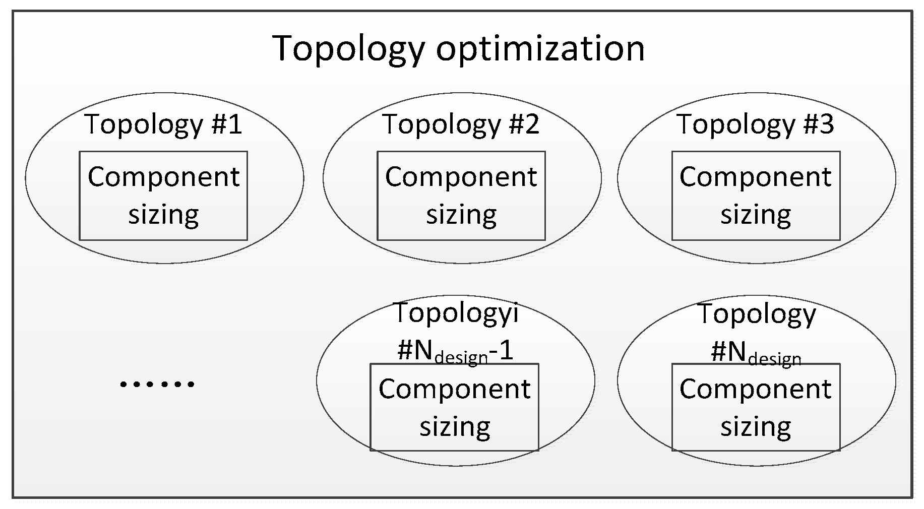
2. Topology Optimization via Exhaustive Search
2.1. Problem Definition
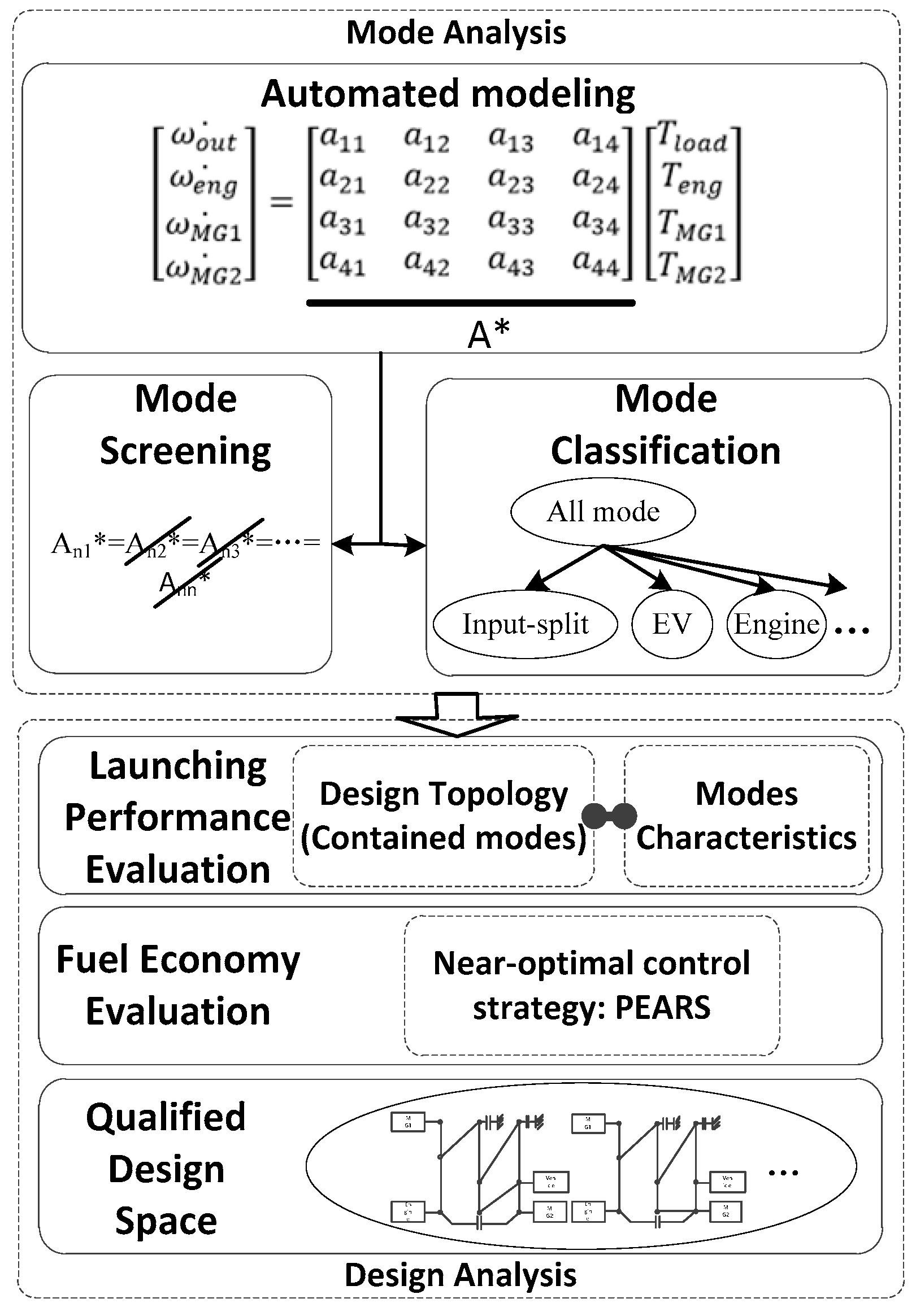
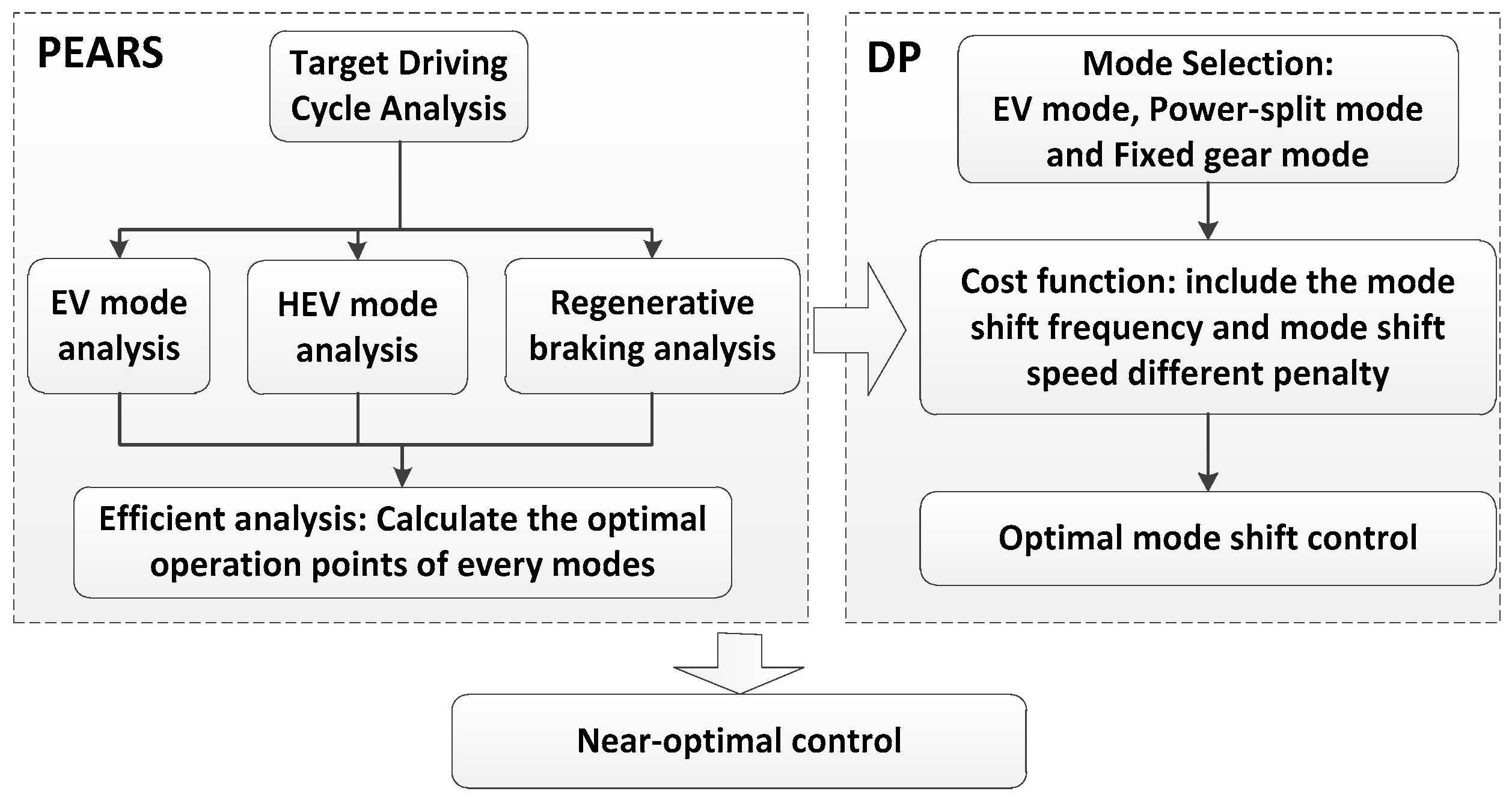
2.2. System Modeling
2.3. Exhaustive Search
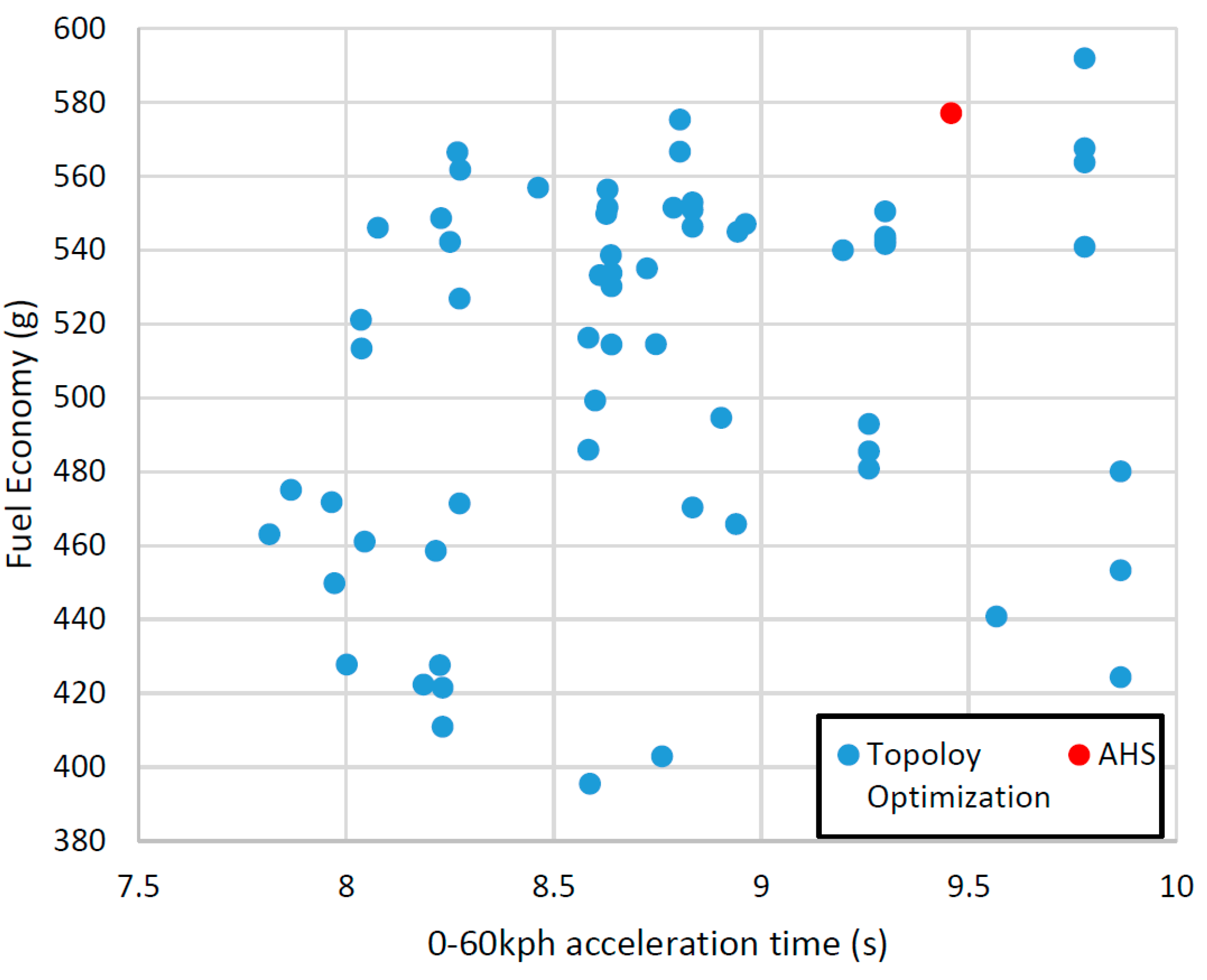
2.4. Case Study
3. Optimal Design
3.1. Component Sizing
3.2. Combined Optimization
3.2.1. Nested Optimization (Approach I)
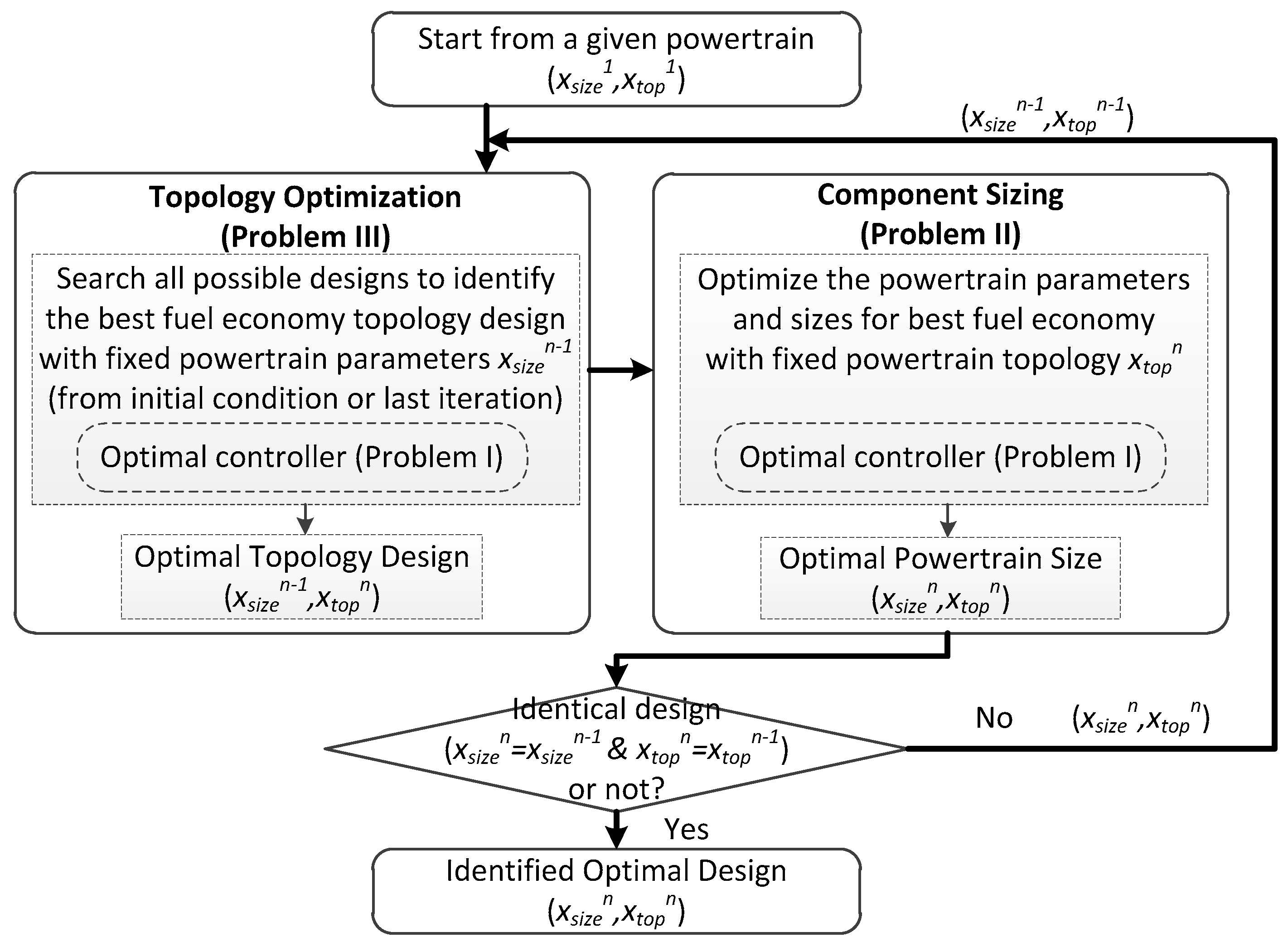
3.2.2. Iterative Optimization (Approach II)
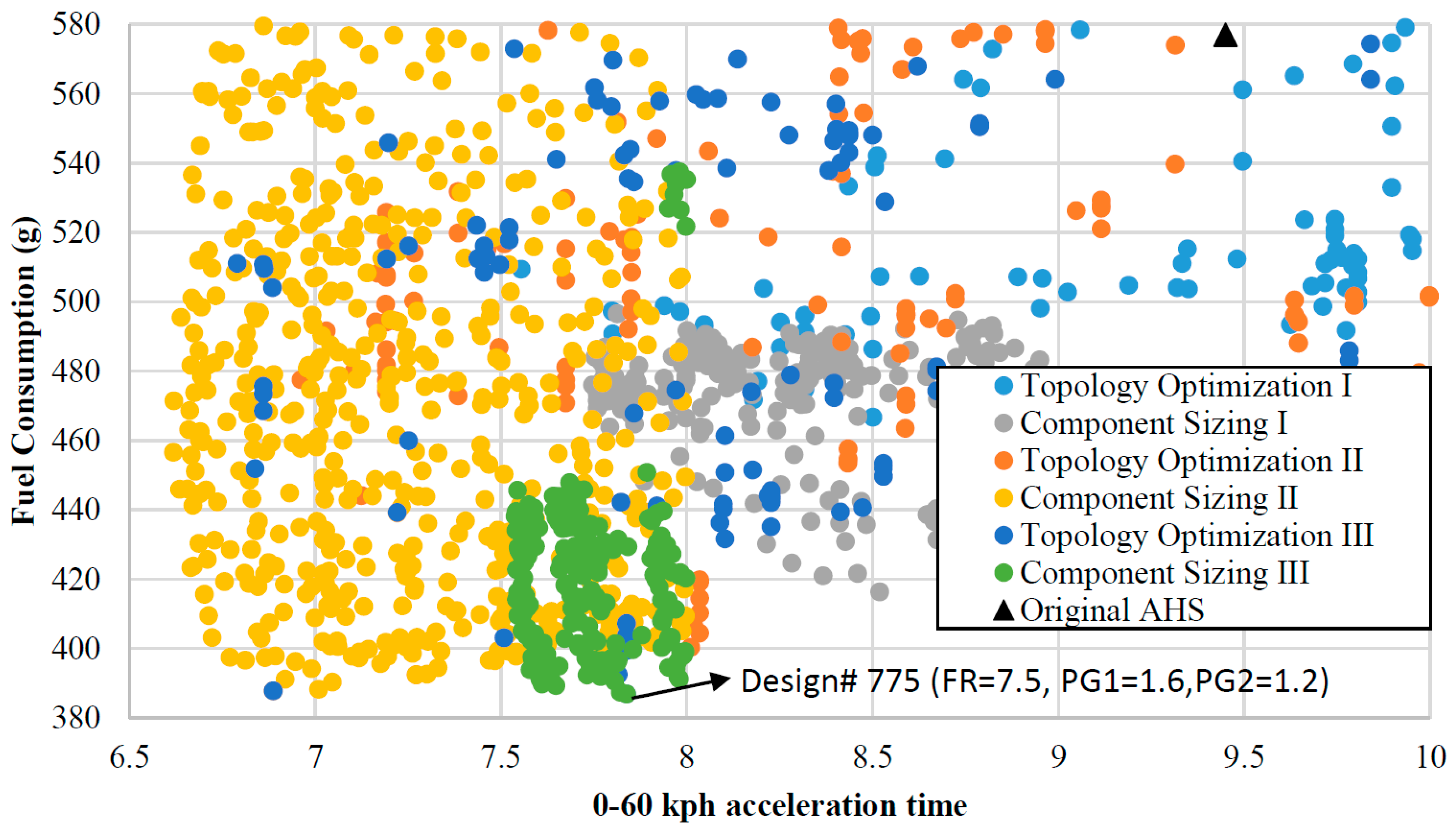
3.3. Results
- (1)
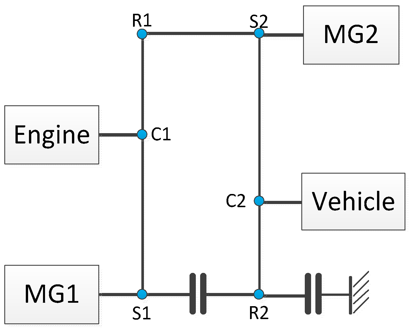
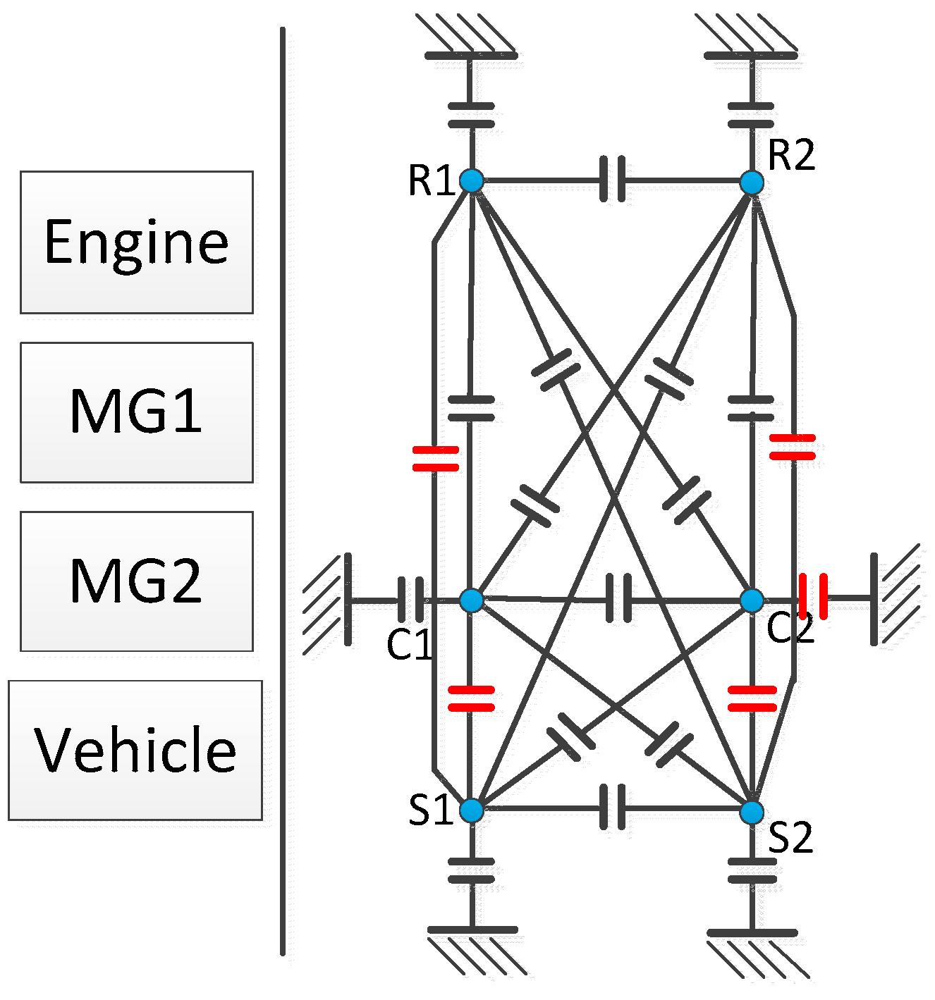
- We fixed the powertrain component locations the same as what was shown in Figure 3.
- (2)
- We only optimize the powertrain parameters (i.e., R/S ratio of PGs and final drive) in this study.
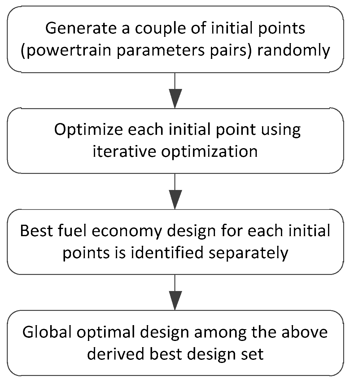
3.4. Enhanced Iterative Optimization
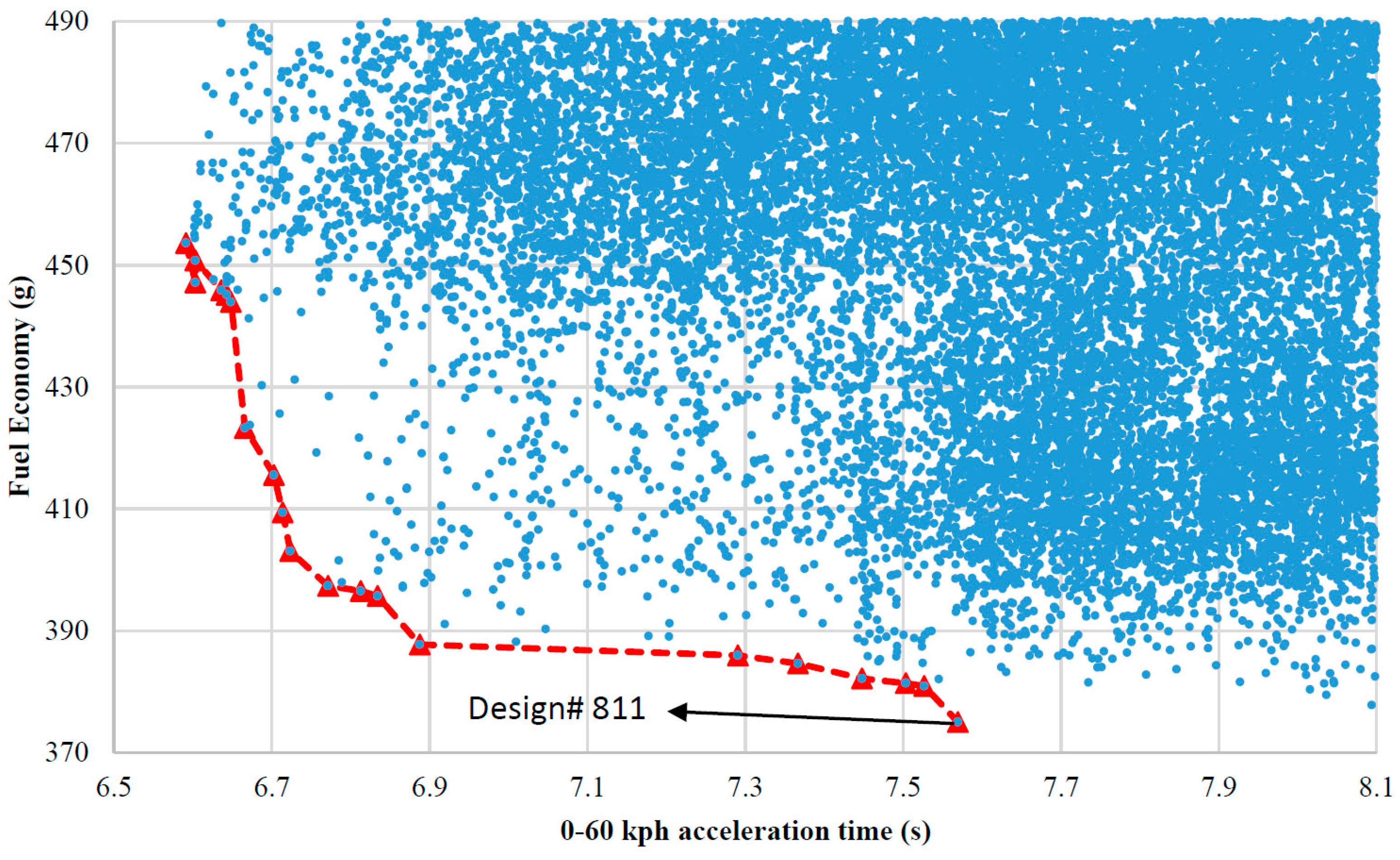
4. Payload Sensitivity Study
5. Conclusions
Acknowledgments
Author Contributions
Conflicts of Interest
References
- National Highway Traffic Safety Administration (NHTSA). Obama Administration Finalizes Historic 54.5 mpg Fuel Efficiency Standards. Available online: http://www.nhtsa.gov/About+NHTSA/Press+Releases/2012/Obama+Administration+Finalizes+Historic+54.5+mpg+Fuel+Efficiency+Standards (accessed on 25 December 2015).
- Alternative Fuels Data Center: Maps and Data. U.S. HEV Sales by Model. 2014. Available online: http://www.afdc.energy.gov/data/10301 (accessed on 25 December 2015). [Google Scholar]
- Miller, J.M. Hybrid electric vehicle propulsion system architectures of the e-CVT type. IEEE Trans. Power Electron. 2006, 21, 756–767. [Google Scholar] [CrossRef]
- Zhang, X.W.; Li, C.T.; Kum, D.; Peng, H. Prius+ and Volt−: Configuration analysis of power-split hybrid vehicles with a single planetary gear. IEEE Trans. Veh. Technol. 2012, 61, 3544–3552. [Google Scholar] [CrossRef]
- Xu, L.F.; Ouyang, M.G.; Li, J.Q.; Yang, F.Y.; Lu, L.G.; Hua, J.F. Optimal sizing of plug-in fuel cell electric vehicles using models of vehicle performance and system cost. Appl. Energy 2013, 103, 477–487. [Google Scholar] [CrossRef]
- Jalil, N.; Kheir, N.; Salman, M. A Rule-Based Energy Management Strategy for a Series Hybrid Vehicle. In Proceedings of the 1997 American Control Conference, Albuquerque, NM, USA, 4–6 June 1997; pp. 689–693.
- Musardo, C.; Rizzoni, G.; Guezennec, Y.; Staccia, B. A-ECMS: An adaptive algorithm for hybrid electric vehicle energy management. Eur. J. Control 2005, 11, 509–524. [Google Scholar] [CrossRef]
- Sciarretta, A.; Back, M.; Guzzella, L. Optimal control of parallel hybrid electric vehicles. IEEE Trans. Control Syst. Technol. 2004, 12, 352–363. [Google Scholar] [CrossRef]
- Lin, C.C.; Peng, H.; Grizzle, J.W.; Kang, J.-M. Power management strategy for a parallel hybrid electric truck. IEEE Trans. Control Syst. Technol. 2003, 11, 839–849. [Google Scholar]
- Larsson, V.; Lars, J.; Egardt, B. Analytic solutions to the dynamic programming subproblem in hybrid vehicle energy management. IEEE Trans. Veh. Technol. 2015, 64, 1458–1467. [Google Scholar] [CrossRef]
- Vinot, E. Time Reduction of the Dynamic Programming Computation in the Case of Hybrid Vehicle. In Proceedings of the 13th International Workshop on OIPE 2014—Optimization and Inverse Problems in Electromagnetism, Delft, The Netherlands, 10–12 September 2014.
- Hu, X.; Murgovski, N.; Johannesson, L.M.; Egardt, B. Optimal dimensioning and power management of a fuel cell/battery hybrid bus via convex programming. IEEE/ASME Trans. Mechatron. 2015, 20, 457–468. [Google Scholar] [CrossRef]
- Nüesch, T.; Elbert, P.; Flankl, M.; Onder, C.; Guzzella, L. Convex optimization for the energy management of hybrid electric vehicles considering engine start and gearshift costs. Energies 2014, 7, 834–856. [Google Scholar] [CrossRef]
- Zhang, X.; Peng, H.; Sun, J. A near-optimal power management strategy for rapid component sizing of multimode power split hybrid vehicles. IEEE Trans. Control Syst. Technol. 2015, 23, 609–618. [Google Scholar] [CrossRef]
- Zou, Y.; Li, D.G.; Hu, X.S. Optimal sizing and control strategy design for heavy hybrid electric truck. Math. Probl. Eng. 2012, 2012. [Google Scholar] [CrossRef]
- Fang, L.C.; Qin, S.Y.; Xu, G.; Li, T.L.; Zhu, K.M. Simultaneous optimization for hybrid electric vehicle parameters based on multi-objective genetic algorithms. Energies 2011, 4, 532–544. [Google Scholar] [CrossRef]
- Ebbesen, S.; Doenitz, C.; Guzzella, L. Particle swarm optimisation for hybrid electric drive-train sizing. Int. J. Veh. Des. 2012, 58, 181–199. [Google Scholar] [CrossRef]
- Wu, L.H.; Wang, Y.N.; Yuan, X.F.; Chen, Z.L. Multiobjective optimization of HEV fuel economy and emissions using the self-adaptive differential evolution algorithm. IEEE Trans. Veh. Technol. 2011, 60, 2458–2470. [Google Scholar] [CrossRef]
- Shankar, R.; Marco, J.; Assadian, F. The novel application of optimization and charge blended energy management control for component downsizing within a plug-in hybrid electric vehicle. Energies 2012, 5, 4892–4923. [Google Scholar] [CrossRef]
- Murgovski, N.; Johannesson, L.; Sjoberg, J.; Egardt, B. Component sizing of a plug-in hybrid electric powertrain via convex optimization. Mechatronics 2012, 22, 106–120. [Google Scholar] [CrossRef]
- Sundström, O.; Guzzella, L.; Soltic, P. Torque-assist hybrid electric powertrain sizing: From optimal control towards a sizing law. IEEE Trans. Control Syst. Technol. 2010, 18, 837–849. [Google Scholar] [CrossRef]
- Nuesch, T.; Ott, T.; Ebbesen, S.; Guzzella, L. Cost and Fuel-Optimal Selection of HEV Topologies Using Particle Swarm Optimization and Dynamic Programming. In Proceedings of the 2012 American Control Conference (ACC), Montreal, QC, Canada, 27–29 June 2012; pp. 1302–1307.
- Zhang, X.W.; Peng, H.; Sun, J. A Near-Optimal Power Management Strategy for Rapid Component Sizing of Power Split Hybrid Vehicles with Multiple Operating Modes. In Proceedings of the 2013 American Control Conference (ACC), Washington, DC, USA, 17–19 June 2013; pp. 5972–5977.
- Liu, J.M.; Peng, H. A systematic design approach for two planetary gear split hybrid vehicles. Veh. Syst. Dyn. 2010, 48, 1395–1412. [Google Scholar] [CrossRef]
- Bayrak, A.E.; Ren, Y.; Papalambros, P.Y. Design of Hybrid-Electric Vehicle Architectures Using Auto-Generation of Feasible Driving Modes. In Proceedings of the ASME 2013 International Design Engineering Technical Conferences and Computers and Information in Engineering Conference: American Society of Mechanical Engineers, Portland, OR, USA, 4–7 August 2013; p. V001T01A005.
- Kang, M.; Kim, H.; Kum, D. Systematic Configuration Selection Methodology of Power-Split Hybrid Electric Vehicles with a Single Planetary Gear. In Proceedings of the ASME 2014 Dynamic Systems and Control Conference: American Society of Mechanical Engineers, San Antonio, TX, USA, 22–24 October 2014; p. V001T15A001.
- Zhang, X.; Li, S.; Peng, H.; Sun, J. Efficient exhaustive search of power split hybrid powertrains with multiple planetary gears and clutches. J. Dyn. Sys. Meas. Control 2015, 137. [Google Scholar] [CrossRef]
- Silvas, E.; Hofman, T.; Serebrenik, A.; Steinbuch, M. Functional and cost-based automatic generator for hybrid vehicles topologies. IEEE/ASME Trans. Mechatron. 2015, 20, 1561–1572. [Google Scholar] [CrossRef]
- Klemen, D.; Schmidt, M.R. Two-Mode, Compound-Split, Electro-Mechanical Vehicular Transmission Having Significantly Reduced Vibrations. U.S. Patent 6,358,173, 19 March 2002. [Google Scholar]
- Holmes, A.G.; Schmidt, M.R. Hybrid Electric Powertrain Including a Two-Mode Electrically Variable Transmission. U.S. Patent 6,478,705, 12 November 2002. [Google Scholar]
- Conlon, B.M.; Blohm, T.; Harpster, M.; Holmes, A.; Palardy, M.; Tarnowsky, S. The next generation “Voltec” extended range EV propulsion system. SAE Int. J. Altern. Powertrains 2015, 4, 248–259. [Google Scholar] [CrossRef]
- Hallmark, S.; Wang, B.; Qiu, Y.; Sperry, R. Evaluation of In-Use Fuel Economy for Hybrid and Regular Transit Buses. J. Transp. Technol. 2013, 3, 52–57. [Google Scholar] [CrossRef]
- Allison Hybrid H40 EP/H50 EP. Available online: http://www.allisontransmission.com/docs/default-source/marketing-materials/sa5983en-h40-50-ep1BCB31AC06C2F2B94ACCEED0.pdf?sfvrsn=4 (accessed on 25 December 2015).
- Zhuang, W.; Zhang, X.; Zhao, D.; Peng, H.; Wang, L. Optimal design of three-planetary-gear power-split hybrid powertrains. Int. J. Automot. Technol. 2016, 17, 299–309. [Google Scholar] [CrossRef]
- Bayrak, A.E.; Ren, Y.; Papalambros, P.Y. Optimal Dual-Mode Hybrid Electric Vehicle Powertrain Architecture Design for a Variety of Loading Scenarios. In Proceedings of the ASME 2014 International Design Engineering Technical Conferences and Computers and Information in Engineering Conference: American Society of Mechanical Engineers, Buffalo, NY, USA, 17–20 August 2014; p. V003T01A005.
- Mendes, E. In U.S., Self-Reported Weight Up Nearly 20 Pounds Since 1990. Available online: http://www.gallup.com/poll/150947/self-reported-weight-nearly-pounds-1990.aspx (accessed on 25 December 2015).


| Component | Parameter | Value |
|---|---|---|
| Engine | Displacement | Cummins ISB 280 6.7 L |
| Maximum Power | 209 kW @ 1600 RPM | |
| Maximum Torque | 895 Nm @ 1600 RPM | |
| Inertia | 0.82 kg·m2 | |
| MG1, MG2 | Maximum Power | 80 kW |
| Maximum Torque | 450 Nm | |
| Maximum Speed | 9600 RPM | |
| LiFePO4 battery | Maximum Power | 60 Ah |
| Voltage | 900 V | |
| All PG | Ring/Sun ratio | 2 |
| Final Drive | Gear Ratio | 5.38 |
| Vehicle | Mass | 13,380 kg |
| Frontal area | 9.5 m2 | |
| Aero drag coefficient | 0.62 | |
| Rolling Resistance | 0.015 | |
| Tire radius | 0.51 m |
| Optimization Method | Fuel Consumption | Acceleration Time | ||
|---|---|---|---|---|
| Value (g) | Improvement (%) | Value (s) | Improvement (%) | |
| Original AHS | 577 | N/A | 9.45 | N/A |
| Component sizing optimization only | 471.34 | 18.4% | 8.76 | 7.3% |
| Topology optimization only | 395.45 | 31.5% | 8.58 | 9.2% |
| Both component sizing and topology optimization | 375.0 | 35.0% | 7.57 | 19.7% |
| Iteration | Optimization | Optimal Topology | PG1 R/S Ratio | PG2 R/S Ratio | Final Drive Ratio | Acceleration Time (s) | Fuel Consumption (g) |
|---|---|---|---|---|---|---|---|
| Original Parameters | AHS | 6 | 1.5 | 3 | 9.45 | 577 | |
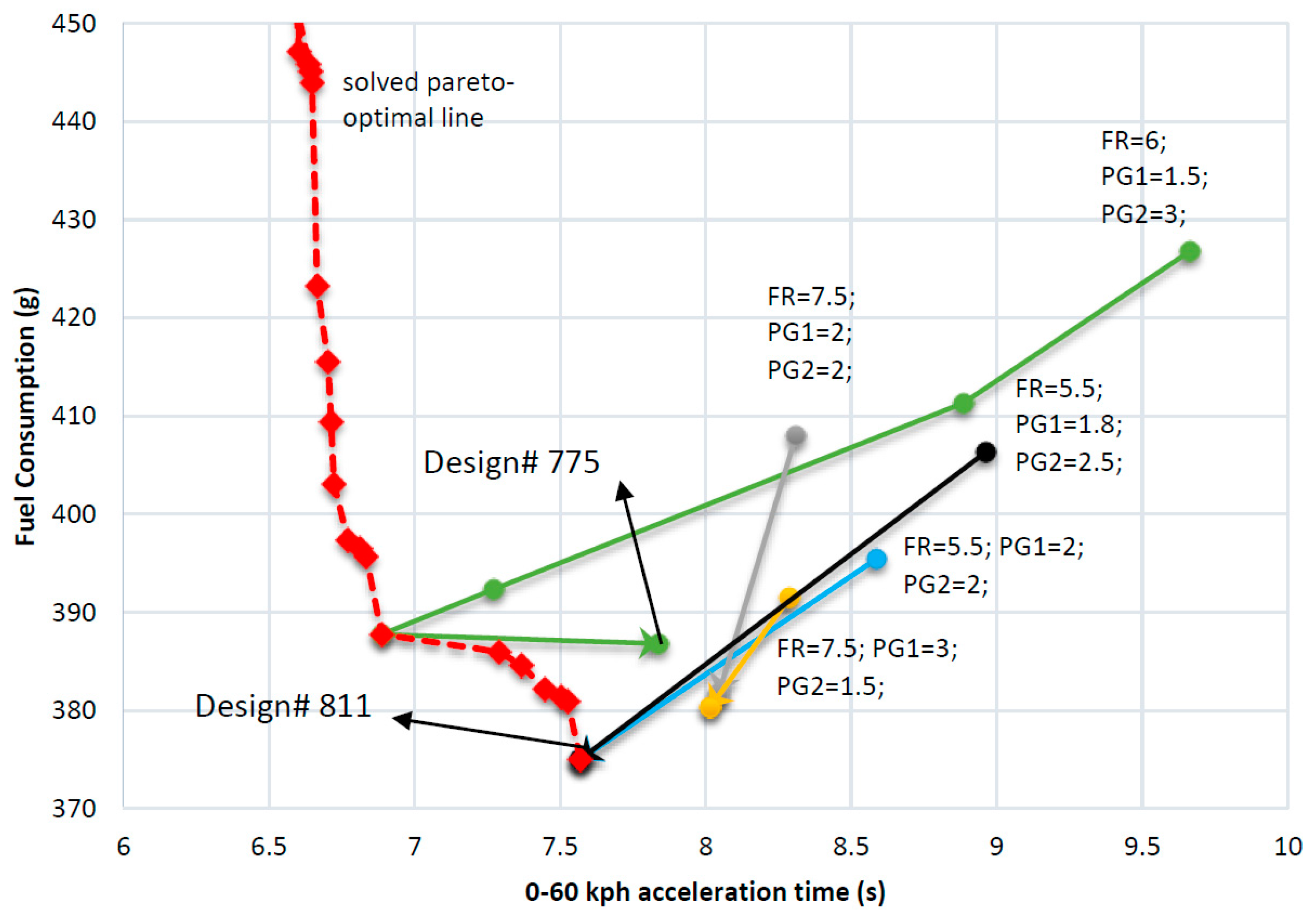
| I | Topology Optimization | Design# 776 | 6 | 1.5 | 3 | 9.664 | 426.79 |
| Component Sizing | Design# 776 | 8 | 1.2 | 1.6 | 8.886 | 411.32 | |
| II | Topology Optimization | Design# 768 | 8 | 1.2 | 1.6 | 7.272 | 392.36 |
| Component Sizing | Design# 768 | 8.5 | 1.6 | 1.2 | 6.887 | 387.75 | |
| III | Topology Optimization | Design# 775 | 8.5 | 1.6 | 1.2 | 7.838 | 386.81 |
| Component Sizing | Design# 775 | 8.5 | 1.6 | 1.2 | 7.838 | 386.81 | |
| IV | Topology Optimization | Design# 775 | 8.5 | 1.6 | 1.2 | 7.838 | 386.81 |
| Component Sizing | Design# 775 | 8.5 | 1.6 | 1.2 | 7.838 | 386.81 | |
| Method Name | Number of Designs Evaluated | Computational Speed | Gained Results |
|---|---|---|---|
| Nested Optimization | 3.4 × 10⁹ | Very slow | Optimal design |
| Iterative Optimization | Up to four iterations | Fastest | Can converge to optimal design but sensitive to initial conditions |
| Enhanced Iterative Optimization | Up to 4mi iterations | mi times slower than iterative optimization | Better than iterative optimization |
| Vehicle Parameters | Payload (kg) | Optimal Topology | PG1 Ratio | PG2 Ratio | Final Drive Ratio |
|---|---|---|---|---|---|
| 1 | 0 | Design 811 | 3 | 1.2 | 8 |
| 2 | 800 | Design 811 | 3 | 1.4 | 7.5 |
| 3 | 1600 | Design 811 | 3 | 1.2 | 8 |
| 4 | 2400 | Design 811 | 3 | 1.6 | 7 |
| 5 | 3200 | Design 811 | 2.6 | 1.4 | 7.5 |
| 6 | 4000 | Design 811 | 2.4 | 1.2 | 8 |
© 2016 by the authors; licensee MDPI, Basel, Switzerland. This article is an open access article distributed under the terms and conditions of the Creative Commons Attribution (CC-BY) license (http://creativecommons.org/licenses/by/4.0/).
Share and Cite
Zhuang, W.; Zhang, X.; Peng, H.; Wang, L. Simultaneous Optimization of Topology and Component Sizes for Double Planetary Gear Hybrid Powertrains. Energies 2016, 9, 411. https://doi.org/10.3390/en9060411
Zhuang W, Zhang X, Peng H, Wang L. Simultaneous Optimization of Topology and Component Sizes for Double Planetary Gear Hybrid Powertrains. Energies. 2016; 9(6):411. https://doi.org/10.3390/en9060411
Chicago/Turabian StyleZhuang, Weichao, Xiaowu Zhang, Huei Peng, and Liangmo Wang. 2016. "Simultaneous Optimization of Topology and Component Sizes for Double Planetary Gear Hybrid Powertrains" Energies 9, no. 6: 411. https://doi.org/10.3390/en9060411
APA StyleZhuang, W., Zhang, X., Peng, H., & Wang, L. (2016). Simultaneous Optimization of Topology and Component Sizes for Double Planetary Gear Hybrid Powertrains. Energies, 9(6), 411. https://doi.org/10.3390/en9060411