1. Introduction
In recent years, there have been more and more applications of distributed generation (DG) systems, due to their advantages of economy, environmental protection, and flexibility. However, DG systems also bring new challenges to the operation and control of power grids, as a result of the negative impact of the high DG penetration rate on the security and stable operation of the power systems [
1,
2]. A microgrid (MG) is a small-scale power system containing DGs, loads, energy storage systems (ESSs) and a control system [
3], which is an effective way to solve the problem of large-scale integration of DGs. MGs have high flexibility so that they can be connected to the distribution network or work in an isolated situation when grid faults occur in the distribution network [
4,
5].
Unlike the single MG, multi-microgrids (MMGs) are a hybrid systems made up of multiple sub-microgrids (SMGs), to meet specific function and control targets [
6,
7,
8]. Considering the independent operation of the SMG and the coordinated operation of the whole system, the control scheme of MMGs should not only ensure the stable operation of each SMG, but also the power exchange between SMGs. With the increasing dependence on the power supply, the consequences of power outages are becoming increasingly severe, hence there is an urgent demand for efficient and reliable black start strategies for MMGs to reduce the interruption time and potential economic losses [
9]. Black start refers to the process of expanding the recovery scope of the power system till the recovery of the entire system. The recovery process does not depend on other networks, which is achieved through the power supplies with black start capability driving the other power supplies without the capability [
10,
11,
12,
13].
In [
10,
11,
12,
13], the restoration procedures of conventional power systems focus on the plant preparation for restart, network energization, and system rebuilding. Therefore, the black-start process of conventional power systems can be divided into three stages: preparation stage, reconfiguration of the network, and load restoration stage [
13]. MG restoration strategies can be divided into parallel (or called bottom-up) strategies and serial (or called top-down) strategies, which are similar to the strategies of conventional power grids [
14,
15,
16,
17,
18]. Parallel strategies promote fast MG recovery. However, parallel strategies have some disadvantages, such as the difficulty to connect the subsystems to MGs, high impulse current when the subsystems are connected, and complications inthe hardware and software design process. Serial strategies can simplify the complexity of hardware and software design, and improve the stability of the system, although longer recovery times are required compared with the parallel strategies. Reference [
17] only puts forward the conditions to launch a MG black start without giving a concrete restoration scheme. In [
14,
18] black-start restoration sequences of actions to be used for a MG after a blackout based on a parallel strategy are proposed. Reference [
16] adopts sequences of actions based on a serial restoration strategy. Nevertheless, these only give qualitative restoration strategies.
The traditional MG black start strategy cannot be directly applied in MMGs, due to the complexity of the MMGs’ structure and control system. Similarly, the black-start process of MMGs can be separated into three stages: selection of the main power supply, network reconfiguration and power supplies and load restoration stage. To complete the black start of the MMGs smoothly, more attention should be given to the coordination between MGs, considering the different power supply characteristics and load characteristics in different MGs [
19,
20]. In [
19,
20] parallel restoration strategies for MMGs’ black start based on the hierarchical control method are presented, providing a certain reference value for MMGs black starts, but they only give qualitative restoration strategies. Reference [
15] proposed a new decentralized control scheme for managing a cluster of MGs through self-organization, decentralized scheduling and dispatch, which significantly enhances the reliability and power quality for critical loads, providing an idea of stand-alone state control in MMGs during black start procedures. The hybrid distribution mode with three-phase/single-phase (TP/SP) architecture is adopted in residential-type MMGs [
21]. Research on effective black start strategy for TP/SP MMGs is important to realize the rapid restoration of electricity for residents, providing a guarantee for the construction of smart grids.
In this paper, we propose a black start strategy for PV-ESS (photovoltaic-energy storage system) MMGs with three-phase/single-phase architecture. The conventional strategies described in [
15,
19,
20] always adopt parallel restoration schemes, giving only black-start restoration sequences of actions with qualitative restoration strategies. Unlike the conventional strategies, a quantitative strategy for MMGs black start is adopted in this paper. Based on a parallel strategy, it includes the selection strategy for the main power supply and master microgrid, the stand-alone operation strategy, and the grid-connected operation strategy. Furthermore, the proposed black start strategy considers the switching and coordination between the stand-alone operation strategy and the grid-connected operation strategy of sub-microgrids during the black start procedure, whereas in the conventional strategies, the operating control of sub-microgrids was not yet considered.
This paper is organized as follows:
Section 2 describes the topology and control system of the residential-type PV-ESS MMGs with TP/SP architecture. In
Section 3, the black start strategy based on the hierarchical control scheme is presented, including the selection strategy for the main power supply and master microgrid, stand-alone operation strategy, and grid-connected operation strategy. In
Section 4, experimental results from the experimental MMGs setup at the Clean Energy Technology Laboratory (CETLAB) are shown. Finally, the conclusions are provided in
Section 5.
2. Topology and Control System of TP/SP MMGs
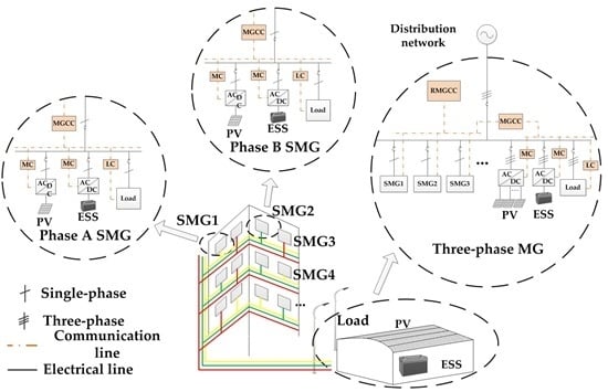
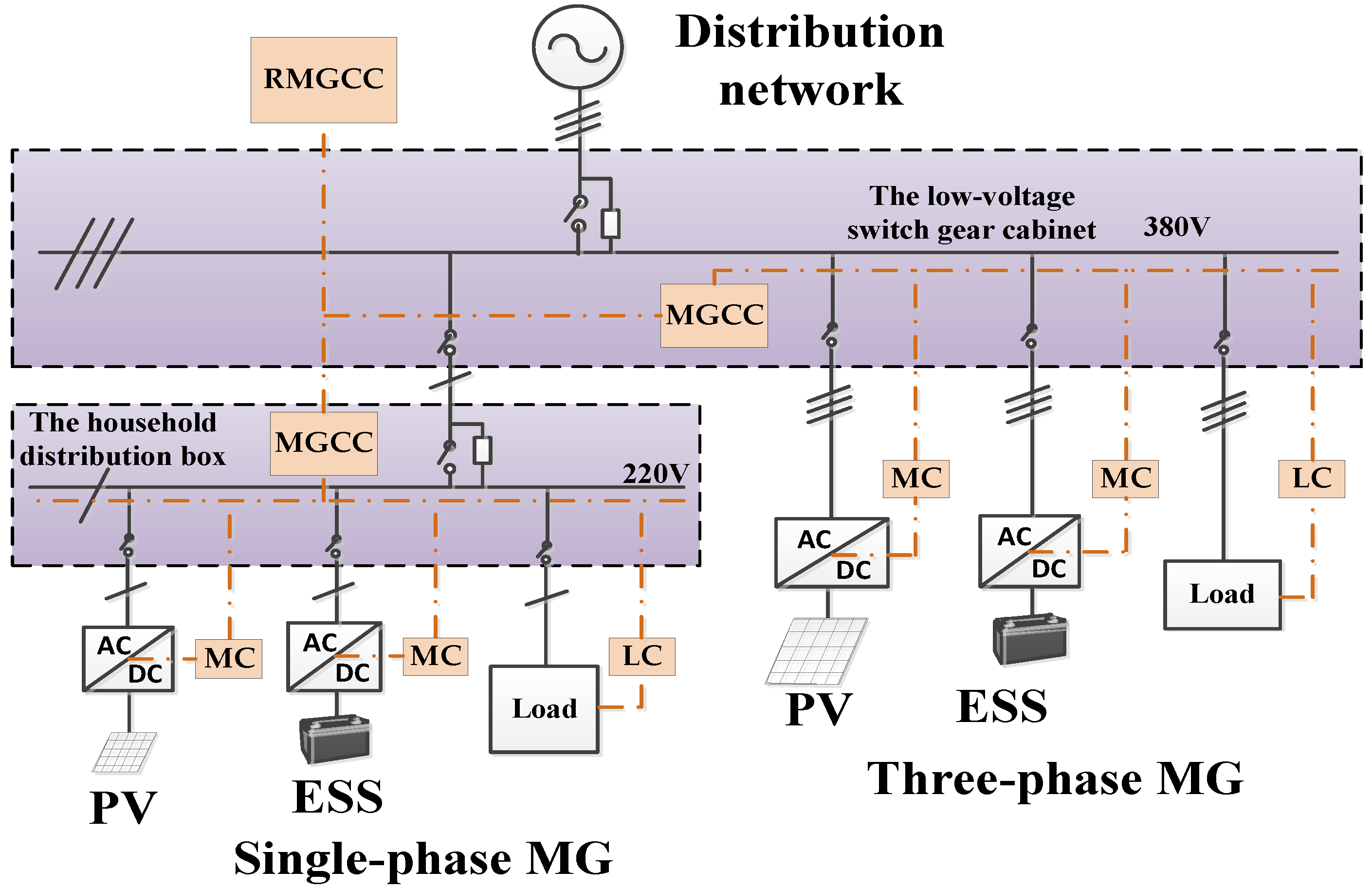
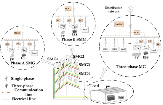
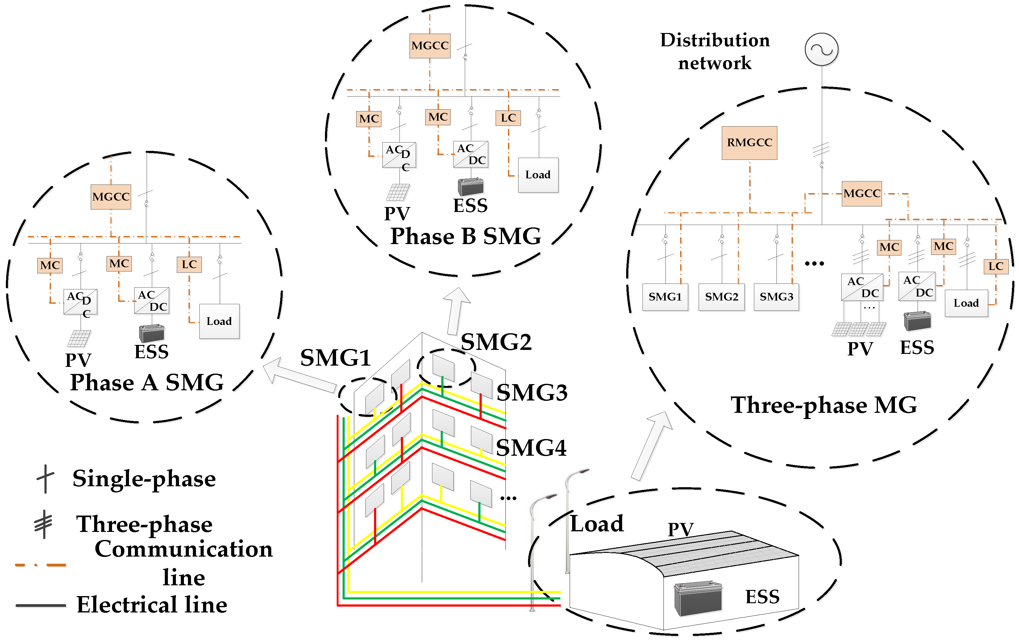
The typical topology of the TP/SP MMGs with PV systems and ESSs is illustrated in
Figure 1. The TP/SP MMGs consist of two layers of MGs. The upper MG is a three-phase structure, which is the three-phase part of the residential-type MMGs, consisting of the three-phase PV, three-phase ESS, and three-phase load. Combined by the single-phase PV, single-phase ESS, and single-phase load, the lower MG is a single-phase structure, which belongs to the part of the residential-type MMGs. As shown in
Figure 1, SMG1, SMG2, and SMG3 are connected to Phases A, B, and C, respectively. All single-phase SMGs are connected to the buses in the three-phase MG through breakers.
Considering the response rate, time scales, and communication needs in MMGs communication, a hierarchical control system is adopted. The hierarchical architecture is divided into three levels, as shown in
Figure 1. The first level is controlled by the bottom controllers, which include the Load Controller (LC) and the Microsource Controller (MC). The second level is controlled by the Microgrid Central Controller (MGCC). The third level is controlled by the Regional Microgrid Central Controller (RMGCC).
MGCCs are responsible for the realization of the control functions of the MG, while the RMGCC realizes the central control of the whole MMGs system to ensure its secure and stable operation and power balance. With the calculations distributed to the lower layer controllers, the control system does not need to set up a server. Only the critical information has to be transmitted, making it possible to perform the necessary calculations cheaply, locally, and dispersedly.
When the TP/SP MMGs are connected to the distribution network, all of the ESSs are operating in the PQ (supply a given active and reactive power set-point) control mode, and the PV systems are operating in the Maximum Power Point Tracking (MPPT) mode.
When the TP/SP MMGs are operating in stand-alone mode, the main power supply are in the VF (supply given voltage and frequency set-point) control mode, whereas the other ESSs are operating in PQ mode, and the PV systems are operating in PQ or MPPT mode.
3. Black Start Strategy
The MG black start strategy cannot be directly applied in TP/SP MMGs owing to the complexity of the MMGs structure and control system. To complete the black start of MMGs smoothly, more attention must be paid to the coordination between MGs, considering the different power supply characteristics and load characteristics in the different MGs.
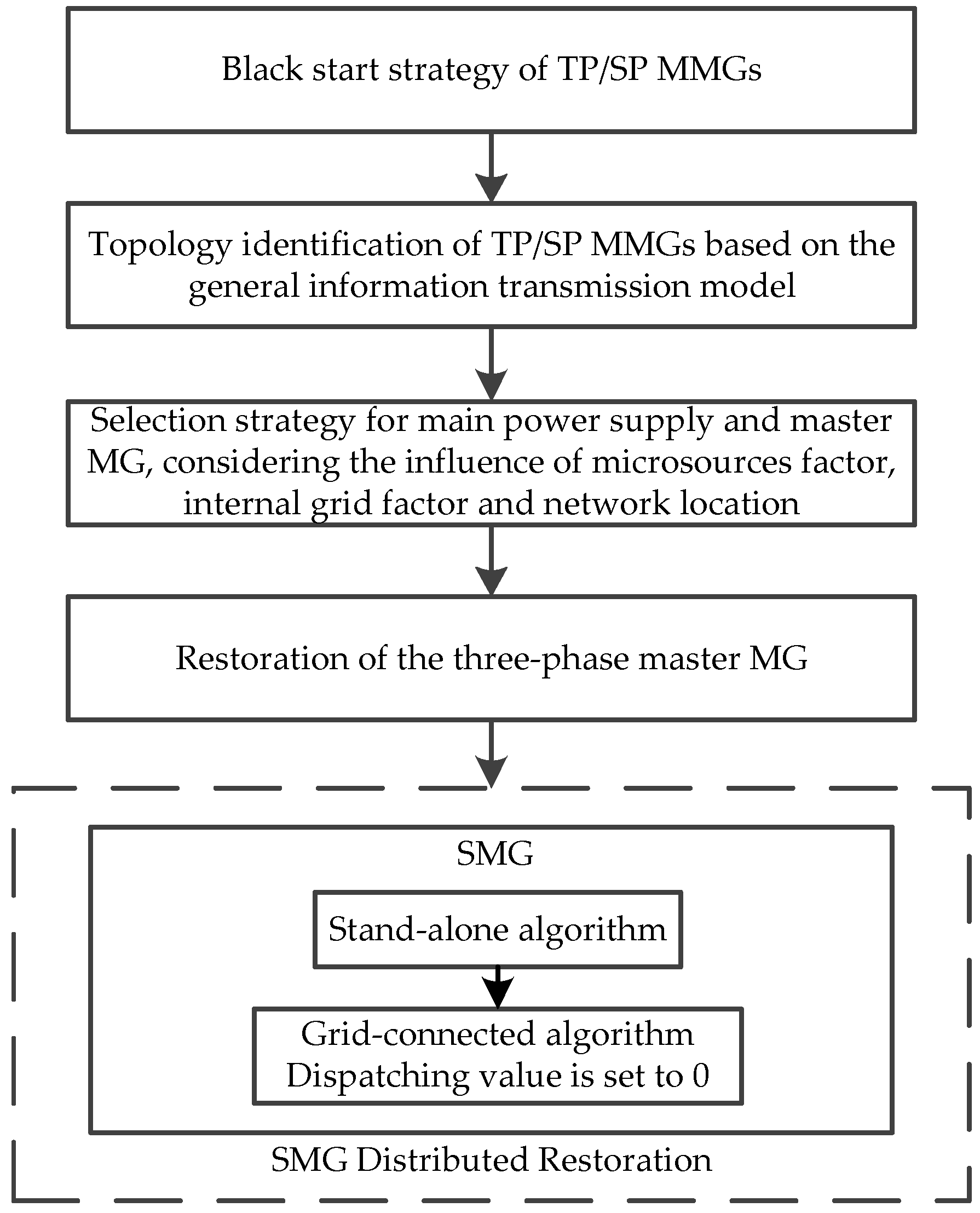
Based on the hierarchical control theory, the black start strategy for PV-ESS MMGs with TP/SP architecture is proposed, as shown in
Figure 2. The TP/SP MMGs complete the process of black start through distributed restoration of SMGs, which is described as follows:
- (1)
The RMGCC identifies the topology of TP/SP MMGs and obtains the necessary information such as the real-time power before the blackout, and the switch status of the equipment.
- (2)
The RMGCC selects the main power supply for the black start. In the three-phase network, the MG with the main power supply is selected as the master MG. With the three-phase ESS operating on VF control mode, the three-phase master MG proceeds the serial restoration. At this stage, the energization of the branches of the network is carried out in several steps downstream the master MG.
- (3)
The MGCCs of single-phase SMGs execute the stand-alone algorithm, with the single-phase ESS operating on VF control mode.
- (4)
Then, the requirements for SMG synchronous connection are checked. If the requirements are satisfied, the breaker of SMG closes, and the SMG’s MGCC enters the grid-connected operation algorithm, with the grid dispatching value set to zero and the SMG’s ESSs operating on PQ control mode. The MGCC of the three-phase master MG still works in the stand-alone state.
3.1. Topology Identification of TP/SP MMGs Based on the General Information Transmission Model
To realize the coordination control of PV-ESS MMGs with different topologies, the communication data formats of the controllers should be defined to establish a general information transmission model. The general information transmission model provides two functions. Firstly the physical topology of PV-ESS MMGs can be accurately identified. In addition, the real-time operating modes and power output can be uploaded. The communication data formats are described as follows.
In Equation (1), the first three elements describe the location of the SMG and corresponding MGCC, and the last three elements describe the power output of the SMG:
where,
i is the layer that the SMG is in (
i ≥ 0, and the smaller
i is, the higher the priority of SMG is);
j is the sequence number of the SMG in the
ith layer (
j ≥ 1, and the smaller
j is, the higher the priority of SMG is);
k denotes the number of the SMG’s phases; (
k = 0 means that it’s a three-phase MG, and
k = 1, 2, 3 means it’s a single-phase MG belong to the Phase-A,B,C);
Pmax,
Pmin and
P0 are the maximum output power, the minimum output power and the real-time output power of the MG, respectively.
In Equation (2), the first six elements describe the location of the ESS, and the last four elements describe the real-time operation state of the ESS:
where,
l means the
lth ESS in the
ith layer SMG
j;
E is the real-time operating mode (
E = 0 denotes VF control mode,
E = 1 denotes PQ control mode, and
E = 2 denotes stand-alone mode);
P,
Q, and
S are the real-time output active power, real-time output reactive power, and the real-time state of charge (SOC) of the ESS, respectively.
In Equation (3), the first six elements describe the location of the PV system, and the last three elements describe the real-time operation state of the PV system:
where
m means the
mth PV in the
ith layer SMG
j;
E is the real-time operating mode of the PV (
E = 0 denotes MPPT control mode,
E = 1 denotes PQ control mode, and
E = 2 denotes off-state).
In Equation (4), the first seven elements describe the load location, and the last three elements describe the real-time operation state of the load:
where
n means the
nth load in the
ith layer SMG
j;
E is the load type (
E = 0 denotes the entirely controllable load, and
E = 1 denotes the uncontrollable load).
The data of the SMGs ([i, j, k, Pmax, Pmin, P0]) is uploaded to the RMGCC, and then the RMGCC calculates the whole real-time output active power ΣP0, the whole maximum output active power ΣPmax and the whole minimum output active power ΣPmin.
3.2. Selection Strategy for Main Power Supply and Master Microgrid
The choice of main power supply is the key step of MG black start, and the main power supply must meet the following requirements:
- (1)
With the capability of adjusting the voltage and frequency.
- (2)
With sufficient reserve capacity.
For the PV-ESS MG, the storage device with high SOC and high capacity should be selected as the main power supply. To complete the MMG black start smoothly, more attention should be paid to the coordination between MGs, considering the different power supply characteristics and load characteristics in different MGs. Three aspects should be considered:
- (1)
The condition of microsources: Ppcs (the rated power of the converter of the ESS); Cap × SOC (the remaining battery capacity). Here, Cap is the capacity of the EES.
- (2)
The in-grid load factor: LH (the ratio of the total critical loads to the total loads in the SMG that the microsource is in).
- (3)
The network location of the microsources: 1/i (i denotes the corresponding layer i of the SMG).
Introduce the new list below:
- (1)
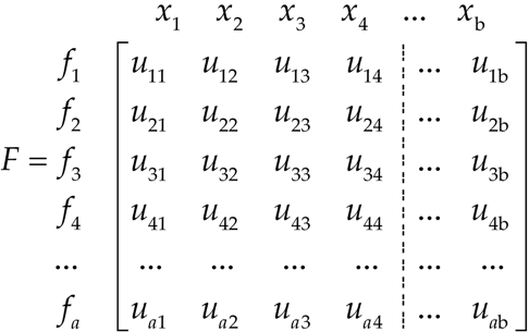
List the decision matrix:
where
xb is the sequence number of the ESS’s PCS (power conditioning system);
uab is the specific indicator corresponding to the
ath decision factor of the
bth ESS;
F is the decision matrix;
fa is the
ath decision factor, such as
Ppcs,
Cap ×
SOC,
LH and 1/
i.
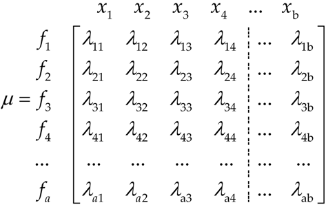
- (2)
The maximum values of the factors {
λm1,
λm2,…,
λmb} are selected as the based value,
λmb = max (
u1b,
u2b,…,
uab). Then the decision matrix is normalized to convert it into the relative optimal membership degree matrix:
where,
μ is the relative optimal membership degree matrix of the decision matrix
F in Equation (5), and 0 ≤
λab ≤ 1.
- (3)
The weighted summations of the column of the relative optimal membership degree matrix μ are calculated with the weight Tn = [t1 t2 t3 … tn]. In order to choose the master microgrid, the selection strategy should consider all the factors above. However, for the main power supply, only the condition of microsources needs to be considered, including Ppcs and Cap × SOC.
3.3. Power Supplies and Load Restoration
In the three-phase network, after the selection of the main power supply, the best ESS’s location information BS: [i, j, k, l, 0, 0] is obtained. The RMGCC selects the three-phase MG that the main power supply is in as the master MG, while the other three-phase SMGs serve as the slave MG. The PV and loads in the master MG are restored successively. The stand-alone algorithm ensures the charging and discharging control, the adjustment of the PV output power and the control of the loads fluctuations, thus to maintain the stable voltage and frequency in the master MG and to provide the voltage and power support for the slave MGs. The slave three-phase SMGs operate on the grid-connected mode with the dispatching value set to Pnet[i, j, k] = 0.
In the single-phase network, once the MGCC receives the black start signal from the RMGCC, the main power supply in the single-phase SMG is started, operating on the VF control mode. The MGCC executes the stand-alone algorithm. When the MGCC receives the connection signal, the breaker is closed. Simultaneously, the SMG is connected to one of the buses in the three-phase master MG, and the MGCC enters the grid-connected algorithm with the dispatching value set to Pnet[i, j, k] = 0. Then the distributed restorations of the ESS, the loads and the PV are proceeded. The stand-alone algorithm and the grid-connected algorithm are the key to maintain the stability of the TP/SP MMGs during the power supplies and loads restoration stage.
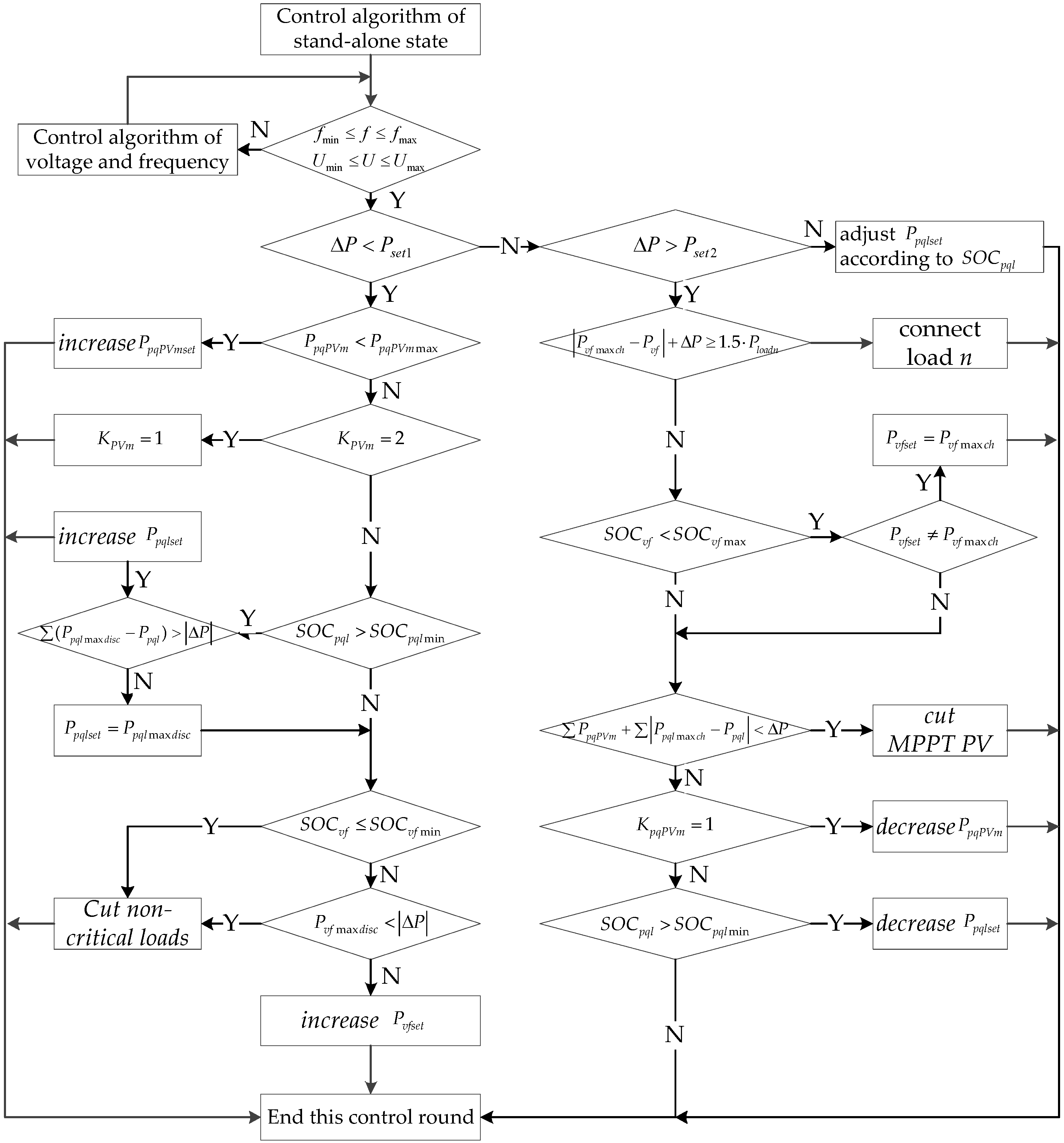
3.3.1. Stand-Alone Algorithm
When the PV-ESS MG operates in stand-alone mode, the main power supply controls the charging and discharging power to reduce the fluctuations caused by the loads and the PV systems. The purpose of the stand-alone algorithm is to ensure the safe and reliable power supply and make full use of renewable energy.
In order to realize the hysteresis control of multi-microsources coordination and to avoid the frequent movement of the control system, the values of
Pset1 and
Pset2 should be chosen reasonably. By judging the size of Δ
P, the MGCC determines whether to connect the loads or to decrease the power of the ESS or to increase the power of the ESS:
where
Ppv is the output power of the PV system;
Pbat is the output power of the ESS;
Ploss is the active power loss;
Pload is the load power.
The flowchart of the stand-alone algorithm of stand-alone state is shown
Figure 3:
where:
Pset1 and Pset2 are respectively the negative threshold value and the positive threshold value; f, fmin, and fmax are the frequency, the lower limit, and the upper limit respectively; U, Umin and Umax are the voltage, the lower limit, and the upper limit respectively; PpqPVm, PpqPVmmin, PpqPVmmax and PpqPVmset are the real-time output active power, the maximum active power, the minimum active power, and the set-point power of the mth PQ adjustable PV, respectively; SOCpql, SOCpqlmin and SOCpqlmax are the real-time SOC, the lower limited SOC, and the upper limited SOC of the lth PQ adjustable ESS respectively; Ppql, Ppqlmaxdisc, Ppqlmaxch and Ppqlset are the real-time output active power, the maximum discharge power, the maximum charge power, and the set-point power of the lth PQ adjustable ESS respectively; SOCvf, and SOCvfmin are the real-time SOC and the lower limited SOC of the main power supply respectively; Pvfmaxdisc, Pvfmaxch, Pvf and Pvfset are the maximum discharge power, the maximum charge power, the real-time power, and the set-point power of the main power supply respectively; Ploadn is the power of the nth load; KpqPVm is the switch state of the mth PQ adjustable PV; KPVm is the switch state of the mth PV system.
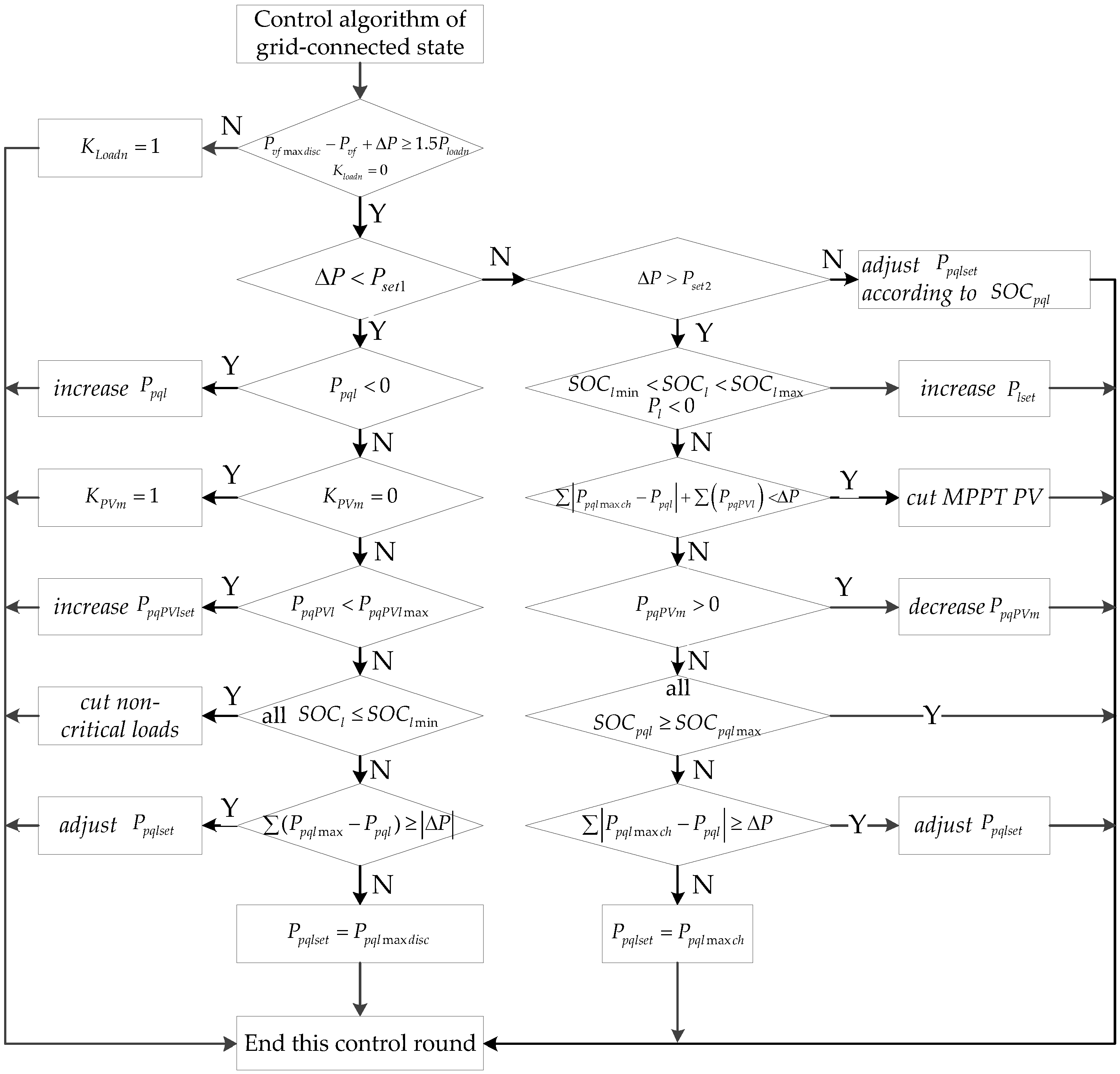
3.3.2. Grid-Connected Algorithm
When the TP/SP MMGs operate in island mode, the voltage and frequency of the slave MG are supported by the master MG. The objective of the grid-connected algorithm is to make maximum use of renewable energy and maintain the tie-line power.
When the MGCC of the SMG enters the grid-connected algorithm, Δ
P transfers to the difference value between the set-point tie-line active power controlled by MGCC and the real-time tie-line active power. The values of
Pset1 and
Pset2 should be set up reasonably to realize the hysteresis control of multi-microsources coordination and avoid the frequent movement of the control system:
where
Pdpt is the set-point tie-line active power controlled by MGCC;
Pnet is the real-time tie-line active power. The flowchart of the grid-connected algorithm of grid-connected state is shown
Figure 4:
where Kloadn is the switch state of the nth load.
4. Experimental Results
To validate the black start restoration strategy of TP/SP MMGs, an experimental setup was built, as shown in
Figure 5, with corresponding topology shown in
Figure 6.
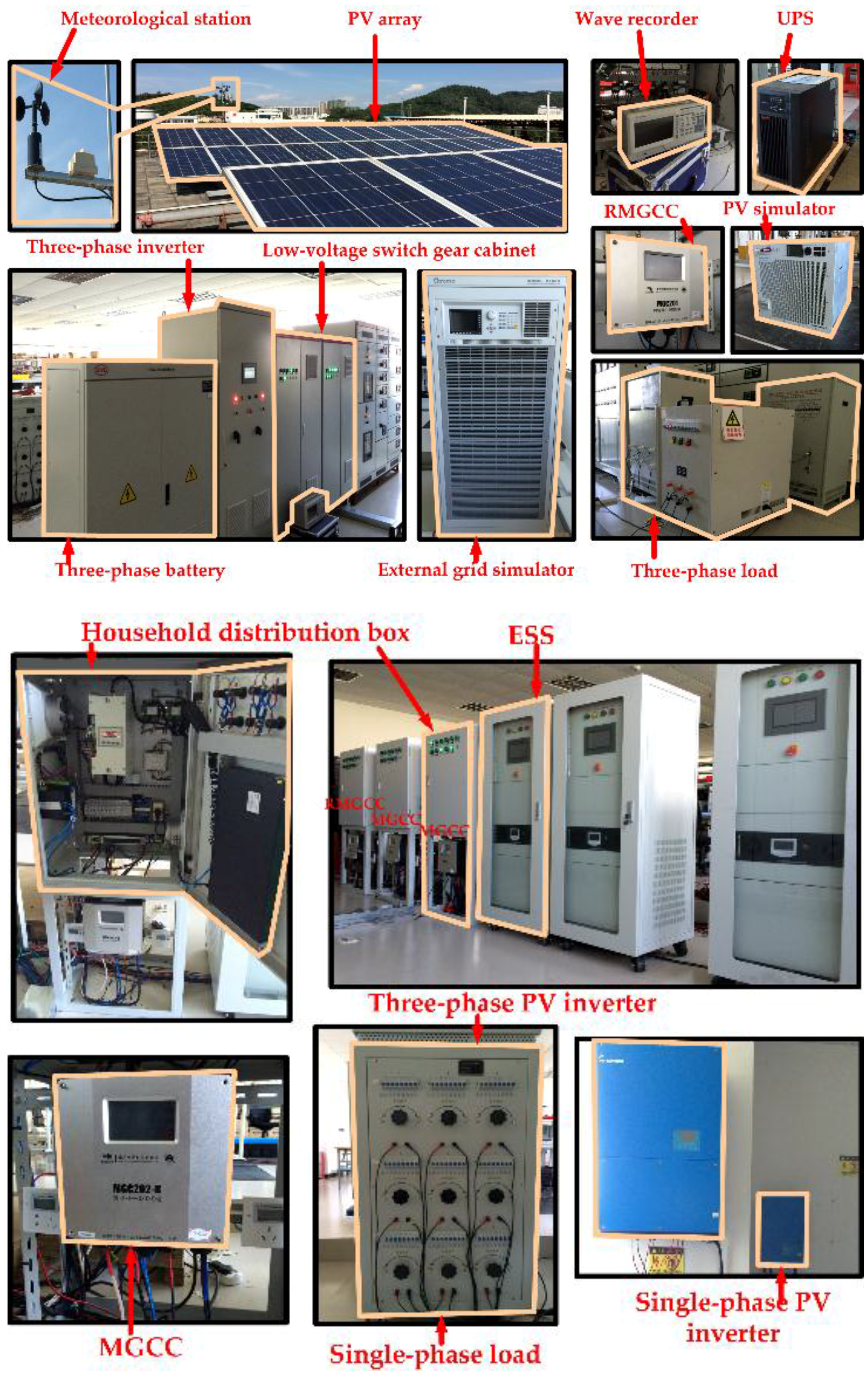
As shown in
Figure 5, the upper MG has a three-phase structure, including a 30 kWp PV system, a 30 kWh ESS and a 5 kW three-phase load (Shenzhen Zenithsun Electronics Technology Co., Ltd., Shenzhen, China). The lower MG has a single-phase structure, and mainly includes a 5 kWp PV system, a 5 kWh ESS and an adjustable single-phase load with maximum value 4.84 kW. The parameters of all components in the real system are shown in
Table 1.
The three-phase PV, ESS and load in the upper MG are controlled by the MGCC (MGC201, applied to three-phase MGs) (China Southern Grid Electric Power Research Institute, Guangzhou, China). The single-phase PV, ESS and load in the lower MG are controlled by the MGCC (MGC202-B (China Southern Grid Electric Power Research Institute), applied to single-phase MGs). Both of them are controlled by another MGC201 serving as the RMGCC. The black start process for the MMGs with TP/SP architecture is as follows:
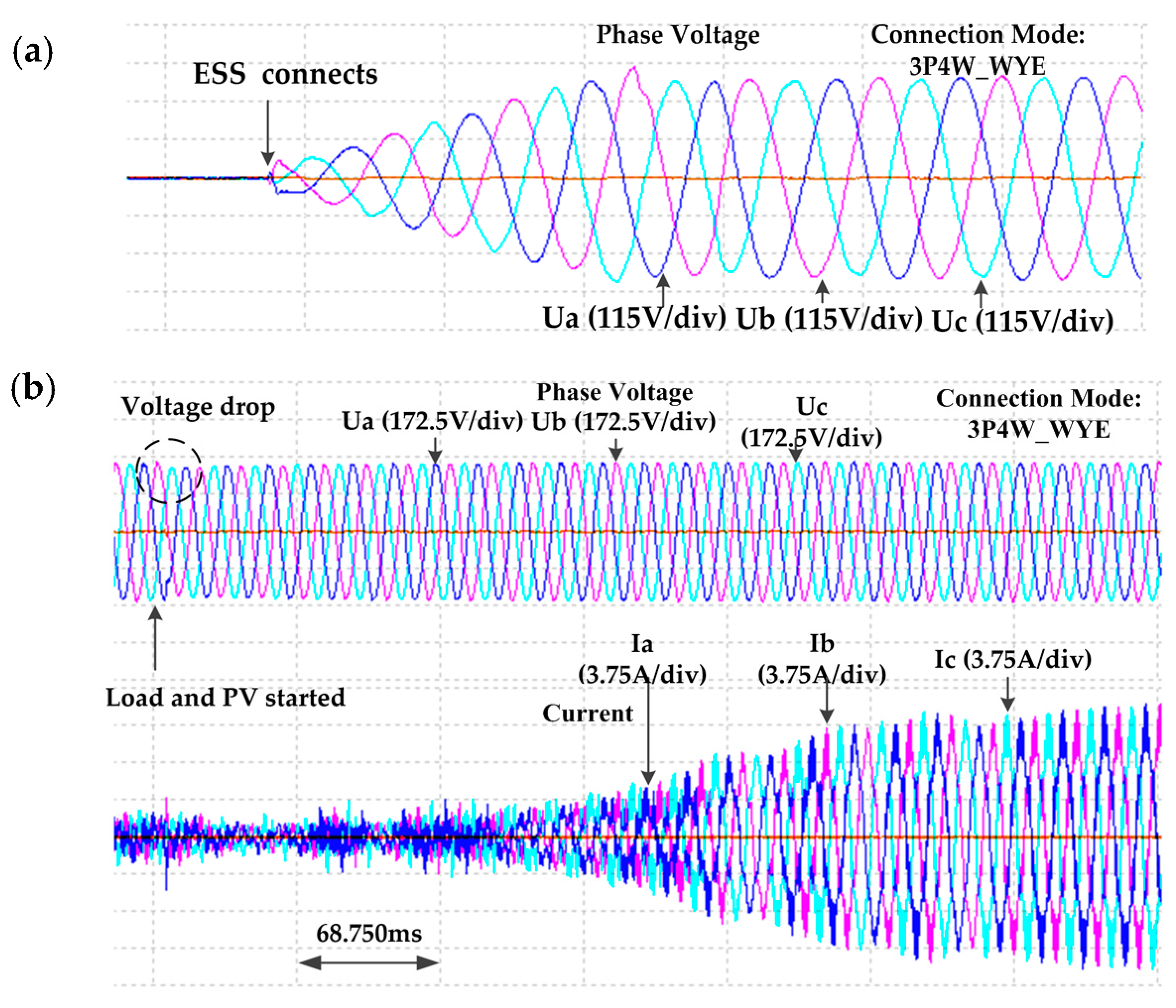
As shown in
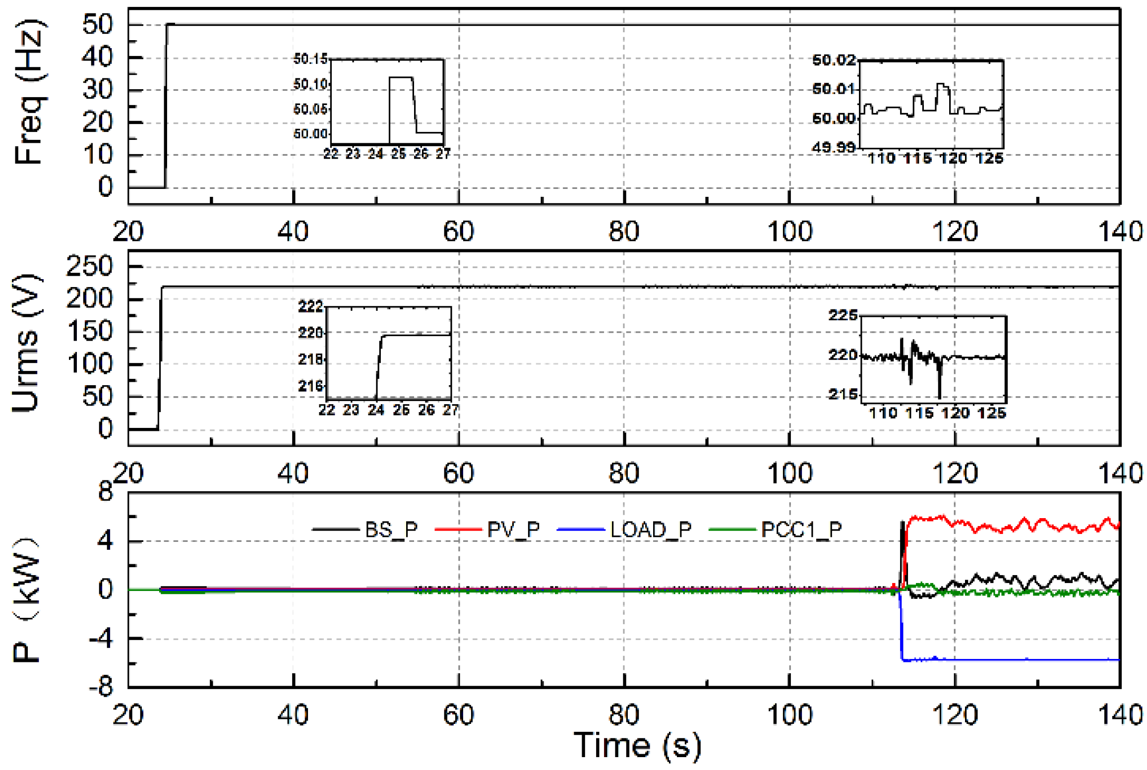
Figure 7, at
t = 24 s, the ESS in the three-phase MG is connected as the main power supply, operating in the VF control mode. At
t = 26 s, the voltage and frequency in the upper MG reach the stable values. As shown in
Figure 8a, the voltage waveform becomes stable after four periods.
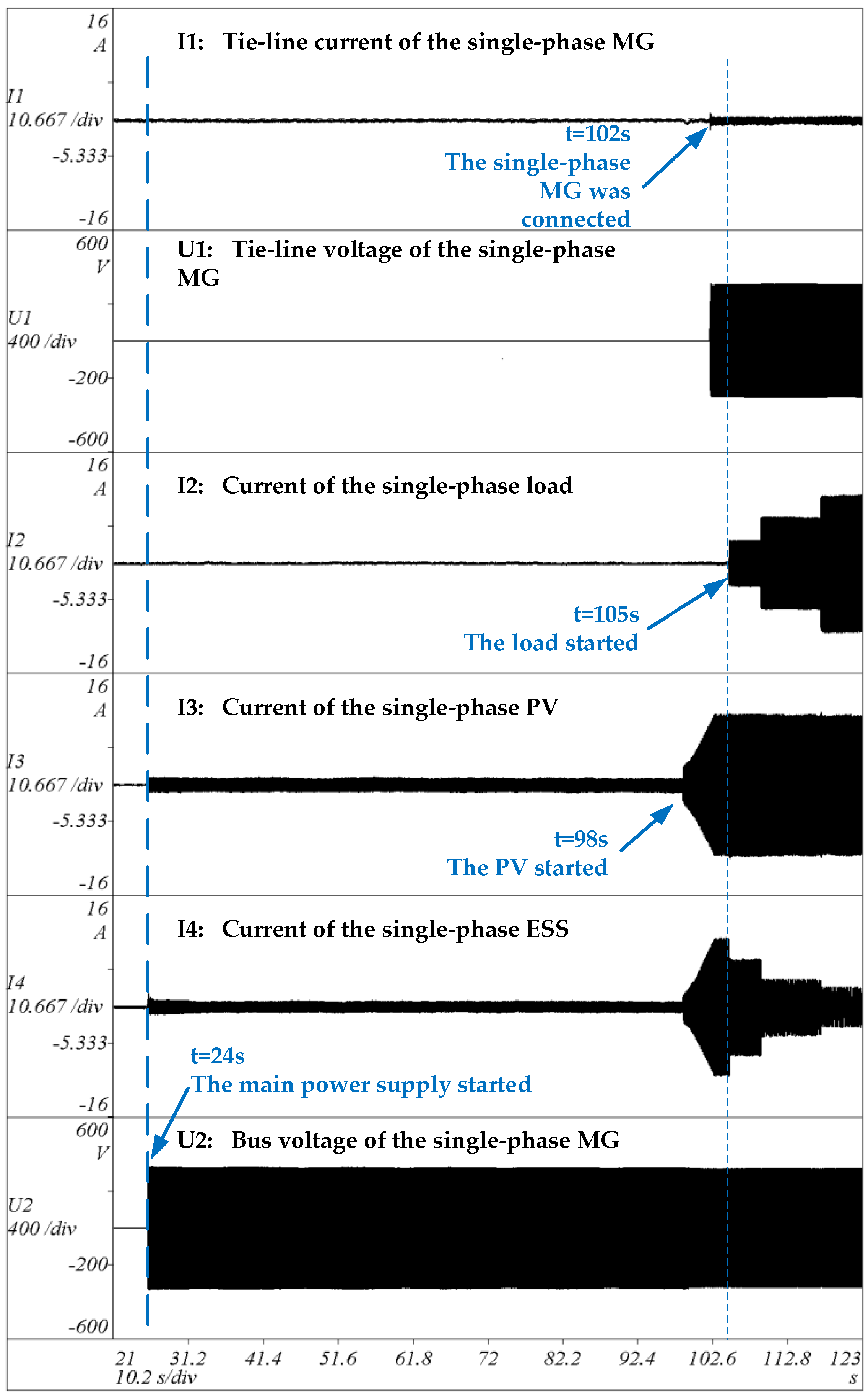
As shown in
Figure 9, at
t = 24 s, the ESS in the single-phase MG is connected, and operates in the VF control mode to establish the stable voltage and frequency. MGC202-B (China Southern Grid Electric Power Research Institute) is operating in the stand-alone algorithm.
The time period for the PV entering into operation is longer than the ESS and loads as the self-detection process of the PV inverter costs about one minute.
As shown in
Figure 9, at
t = 98 s, the single-phase PV in the lower MG starts, and the single-phase ESS begins to charge in order to maintain the power balance in the single-phase MG. At
t = 102 s, the connecting condition of the slave -MG is met, and the breaker of the single-phase MG and the breaker in the household distribution box closes, thus the single-phase MG is connected to the three-phase MG. The control mode of the single-phase ESS transfers to the PQ mode. MGC202-B enters the grid-connected algorithm, with the tie-line power set to zero. As shown in
Figure 7, the tie-line power is maintained at zero, which verifies the effectiveness of the grid-connected algorithm. At
t = 105 s, the single-phase load is attached. To maintain the fixed tie-line power, the charging power is decreased.
As shown in
Figure 7, at
t = 113 s, the connecting condition of the three-phase PV is met.
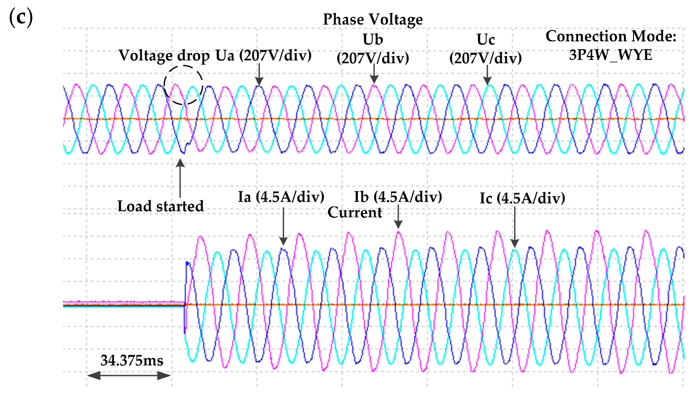
Figure 8b shows the voltage and current waveforms when the PV system starts. The PV system is operated in PQ control mode, with the output power set to 5 kW. At this moment, the three-phase load is connected.
Figure 8c shows the voltage and current waveforms when the load is connected.
As can be observed in
Figure 7, the output active power of the ESS increases to compensate the power shortage.
Figure 8c shows that slight bus voltage drop is yielded when the three-phase load connected, and the voltage recovers rapidly after the power adjustment of the ESS. As shown in
Figure 9, at
t = 109 s and
t = 117 s, the single-phase load power increases. To maintain the fixed tie-line power, the charging power of the single-phase ESS is decreased.


