Article

A Comparative Study of Open and Closed Heat-Engines for Small-Scale CHP Applications

Department of Mechanical, Materials and Manufacturing Engineering, University of Nottingham, University Park, Nottingham NG7 2RD, UK
*
Author to whom correspondence should be addressed.
These authors contributed equally to this work.
Energies 2016, 9(3), 130; https://doi.org/10.3390/en9030130
Submission received: 4 December 2015 / Revised: 17 January 2016 / Accepted: 22 February 2016 / Published: 25 February 2016

Abstract

:
In this paper the authors compare and contrast open and closed-cycle heat engines. First of all, by way of example and to aid discussion, the performance of proprietary externally heated closed-cycle Stirling engines is compared with that of internally heated open Otto cycle engines. Both types of engine have disadvantages and merits and this suggested that in order to accommodate the best of both engine types an externally-heated open-cycle engine might offer a more satisfactory solution for small-scale combined heat and power (CHP) systems. To investigate this possibility further the paper goes on to compare the performance of externally-heated and recuperated Joule hot-air cycle engines with that of an externally-heated closed Stirling cycle engines. The results show that an externally heated recuperated open Joule cycle engine can exceed that of a closed cycle Stirling engine operating between the same heat source and sink temperatures when a variable temperature heat source is used.

1. Introduction

The paper begins by comparing the performance of proprietary externally-heated closed-cycle reciprocating Stirling engines with proprietary internally-heated reciprocating open Otto cycle engines. Disadvantages and merits for both engine types are discussed and from this it is concluded that some form of externally-heated open-cycle engine might offer a practical solution to the problem of selecting an engine cycle suitable for small-scale power generation. To support this view the paper goes on to compare the performance of a recuperated reciprocating open Joule cycle engine with that of an externally-heated reciprocating closed Stirling cycle engine.
Over recent years there has been an increase in the amount being written on the various types of Stirling cycle engine, particularly for applications in advanced combined heat and power energy systems. The cycle was invented by Robert Stirling in 1816 [1] and two recent papers [2,3] provide useful summaries of progress in this area. The constant pressure cycle too has a long history. In 1791 John Barber patented the first engine of this type, which incorporated an air compressor, a combustion chamber and an early type of turbine [4]. However, it was James Prescott Joule (1850) that provided the first theoretical description of the constant pressure cycle [5], more than 20 years before George Brayton invented his improvements [6]. It is interesting to note that both Joule’s and Brayton’s engines were reciprocating piston types and both the original work of Barber and the improvements by Brayton were based on internal combustion engines but that Joule’s own test engine was externally heated. More recently Moss, Roskilly and Nanda proposed a reciprocating Joule-cycle engine for domestic combined heat and power systems [7].
This paper compares and contrasts the performance of close and open cycle engines. The former being externally heated whilst the latter are almost all internally heated; and are commonly referred to as internal combustion engines.

2. Externally Heated Versus Internally Heated Engine Cycles

2.1. Comparison of Thermal Efficiency

For a given cycle temperature ratio there is no doubt that the thermodynamic efficiency of a fully reversible Carnot cycle engine cannot be bettered. In practice, however, the low value of indicated mean-effective-pressure (imep) of the Carnot cycle precludes any practical application. In contrast a fully-reversible Stirling cycle engine offers practical imep values with thermodynamic efficiencies equal to those of the Carnot cycle engine with a similar cycle temperature ratio [8]. The same maybe said of both Atkinson and Ericsson cycle engines [9].
Today Stirling cycle engines are used to drive relatively small electricity generators in combined heat and power systems. Being positive displacement machines drive-shaft speeds tend to be low and easily matched to those of electricity generators without the need for large gear boxes. Importantly too, Stirling engines are externally heated and, therefore, can be powered by a wide range of variable temperature heat sources, for example low-grade renewable fuels such as wood chip and other derived fuels that for internally heated engines would be impracticable.
Stirling engines operate in a closed-cycle; meaning that the same working fluid circulates between the hot-side and cold-side of the engine. Therefore both sides of a Stirling cycle engine require a heat exchanger: one to transfer heat from the high temperature heat source to the engine’s working fluid and a second to transfer heat from the working fluid to a cooling medium outside the engine. This is a disadvantage of all closed cycle engines. Because heat must be transferred within a finite-time there must be temperature differences at the hot- and cold-sides of the engine cycle (∆TH and ∆TL), in order to achieve the necessary heat rates. An effect of these necessary temperature differences is to reduce the maximum possible thermodynamic efficiency of an engine. Equation (1) shows thermodynamic efficiency is reduced as ∆TL and ∆TH increase:
η t h = 1 T L T H > 1 T L + Δ T L T H Δ T H
Increasing these temperature differences reduces the required heat exchange area, which in turn reduces the physical size of any externally heated and externally cooled engine but at a cost of reduced thermodynamic efficiency. A further disadvantage of closed cycle engines is the often proposed use of non-benign working fluids, such as iso-propane (organic Rankine cycle), hydrogen (Stirling cycle). Neglecting any environmental or safety issues with some of these working fluids, leakage can problematic and require specialist maintenance on a regular basis, which may be an unwanted additional expense for domestic combined heat and power systems intended to replace conventional water heaters. Even Rankine cycle steam engines, using water as their working fluid, can suffer loss of vacuum pressure at the condenser, which harms their performance. On the other hand open cycle, (air breathing), engines do not suffer this disadvantage and so may be more suited to small scale combined heat and power applications.
For open cycle internal combustion engines, such as the Diesel engine, the ∆TH and ∆TL terms in Equation (1) are removed and so the potential maximum thermodynamic efficiencies of an internally-heated open cycle engines tend to be greater than that of a similar closed cycle engine operating with the same heat source and sink temperatures. It is interesting that the empirical data listed in Table 1, which compares the performance of (gas-fuelled) open Otto cycle engines with (gas-fuelled) closed Stirling cycle engines, (which theoretically at least should have a greater efficiency), also seems to supports this view. In addition to the data listed in Table 1, Conroy, Duffy and Ayompe reported an overall efficiency for electricity generation of 7.9% [3], for the WhisperGen Stirling engine combined heat and power system, which is lower than others listed.
In addition, the physical size of open cycle engines tends to be smaller and lighter in weight than closed cycle machines with similar outputs. This potential for small, light-weight engines led to their general adoption for motorised transport systems. For combined heat and power applications, however, physical size and weight are probably not so important and therefore closed cycle engines have found useful applications: Rankine cycle steam turbine engines for large scale power generation and Stirling cycle engines for small-scale systems.
Open-cycle internal combustion engines are limited to burning refined fuels such as gasoline, liquefied petroleum gas and natural gas. This may be a disadvantage for power generation in areas of the world where the burning of low grade fuels (wood chips, pellets, peat, selected waste or poor quality bio-oils) is the most practical and economic source of high grade heat.
Therefore, an engine which can be both externally heated and based on an open cycle, so that it can run on any fuel or mixture of fuel type(s) and does not require a low-temperature heat exchanger, may offer some advantages over currently available technologies. One such engine-cycle is the constant pressure cycle.

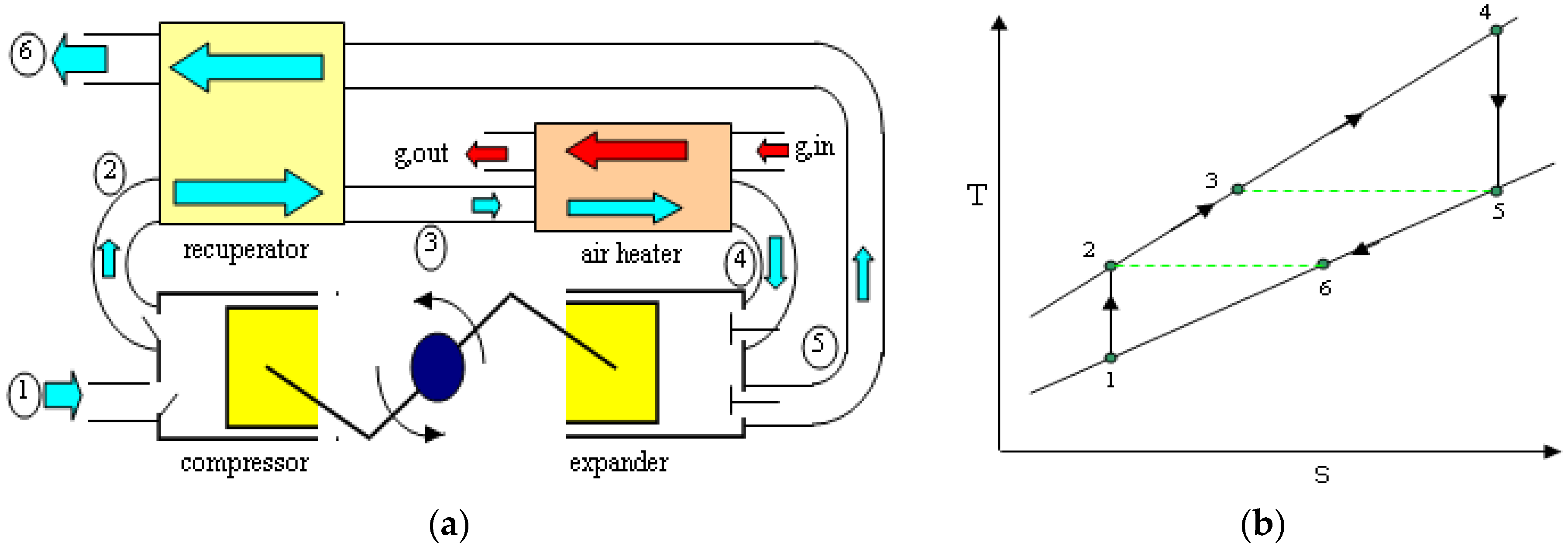
2.2. The Recuperated Constant Pressure Heat Engine Cycle

Figure 1a shows a schematic view of an externally-heated, recuperated, constant pressure Joule cycle (RJC) engine whilst Figure 1b provides a T-s diagram for a fully reversible RJC engine. It is well known that the constant pressure open Joule cycle also provides the theoretical bases for the gas-turbine engine, the analysis of which is well documented in text books [15].
Referring to Figure 1b the processes shown are as listed in Table 2.
The RJC (recuperated Joule cycle) engine does not require external cooling as the working fluid discharges directly to the environment at state-point 6 in Figure 1b. For combined heat and power applications the hot airflow leaving the engine at state-point 6 may be used to; provide space heating, drive a thermally activated cooling cycle or power an organic Rankine cycle (ORC) engine. Any of these additions would further increase the usefulness of the heat source. In addition the waste heat in the combustion gas may also be captured as it leaves the air-heater at state-point g,out, shown in Figure 1a, thus increasing the thermal efficiency of the CHP system as a whole.

3. Comparison of the Externally Heated RJC (Recuperated Joule Cycle) and Stirling Cycle

Figure 2 shows T-s diagrams for an internally reversible RJC engine and internally reversible Stirling cycle engine both with finite-time heat transfer between source and sink.
For the purpose of analysis the following assumptions were made:
(1)
Both the RJC and Stirling cycles are internally reversible.
(2)
Both cycles are heated externally via identical heat exchangers using hot combustion flue-gas: a variable temperature heat source.
(3)
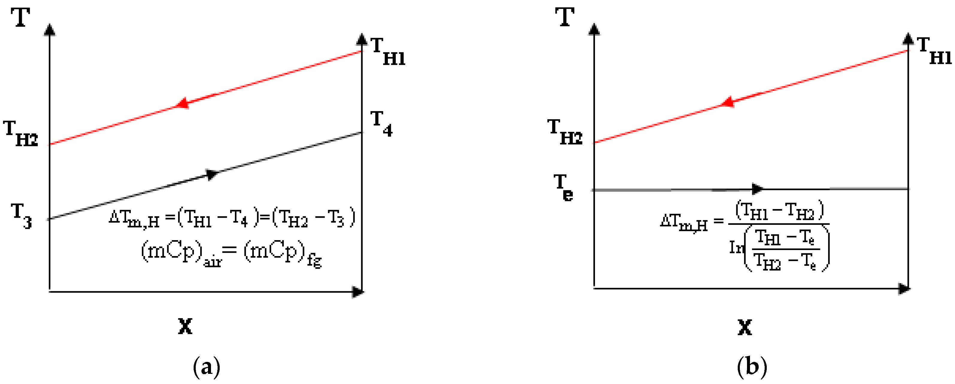
In both engines the combustion gases are assumed to enter the high-temperature heat exchanger at the same temperature (TH1) and leave at the same temperature (TH2).
(4)
Both cycles are assumed to absorb heat at the same rate (J/s).
(5)
Either ∆Tm,H,RJC = ∆Tm,H,SC or ATDH,RJC = ATDH,RC (both possibilities were investigated).
(6)
For the RJC the heat capacity rate, (CH), of its working fluid equals that of the combustion gases.
(7)
The working fluid within both cycles is dry-air, which is assumed to be a perfect gas.
(8)
The Stirling cycle is assumed to reject heat to its environment (low-temperature sink) via an air-cooled heat exchanger and the ambient air entering this heat exchanger has the same temperature as the air entering the compressor of the RJC engine: T1 = Tamb in Figure 2a = TL1 in Figure 5.
(9)
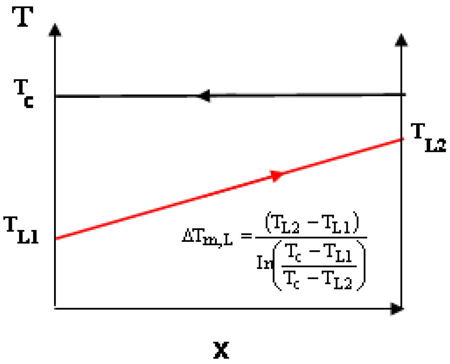
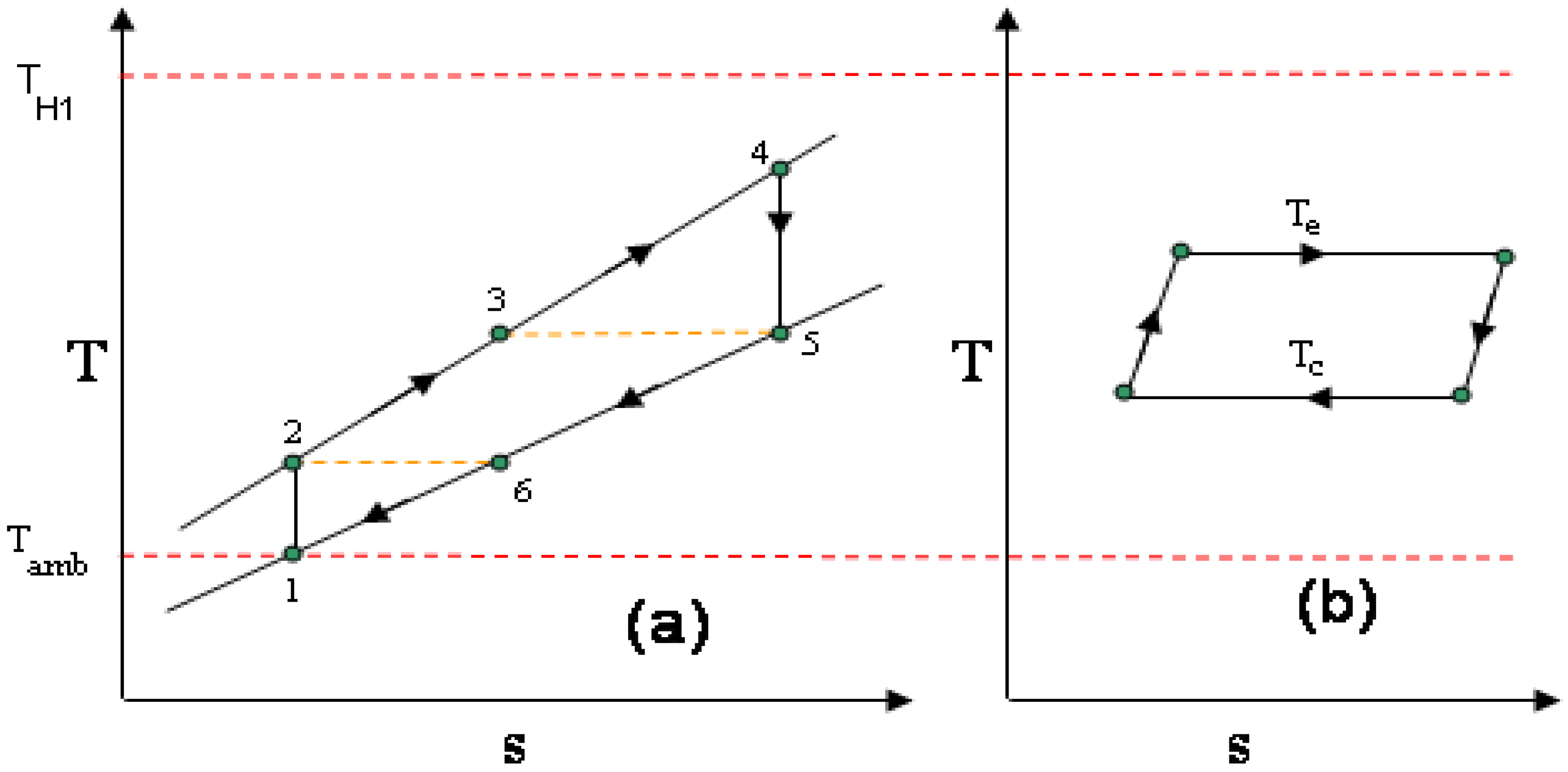
The temperature of the air leaving the Stirling cycle’s low-temperature heat exchanger equals that leaving the recuperator of the RJC: T6 in Figure 2a equals TL2 in Figure 5. This is thought to be a reasonable assumption if the waste heat from both cycles is to be utilized for heating purposes because it would mean its temperature in both cases would be equal.
(10)
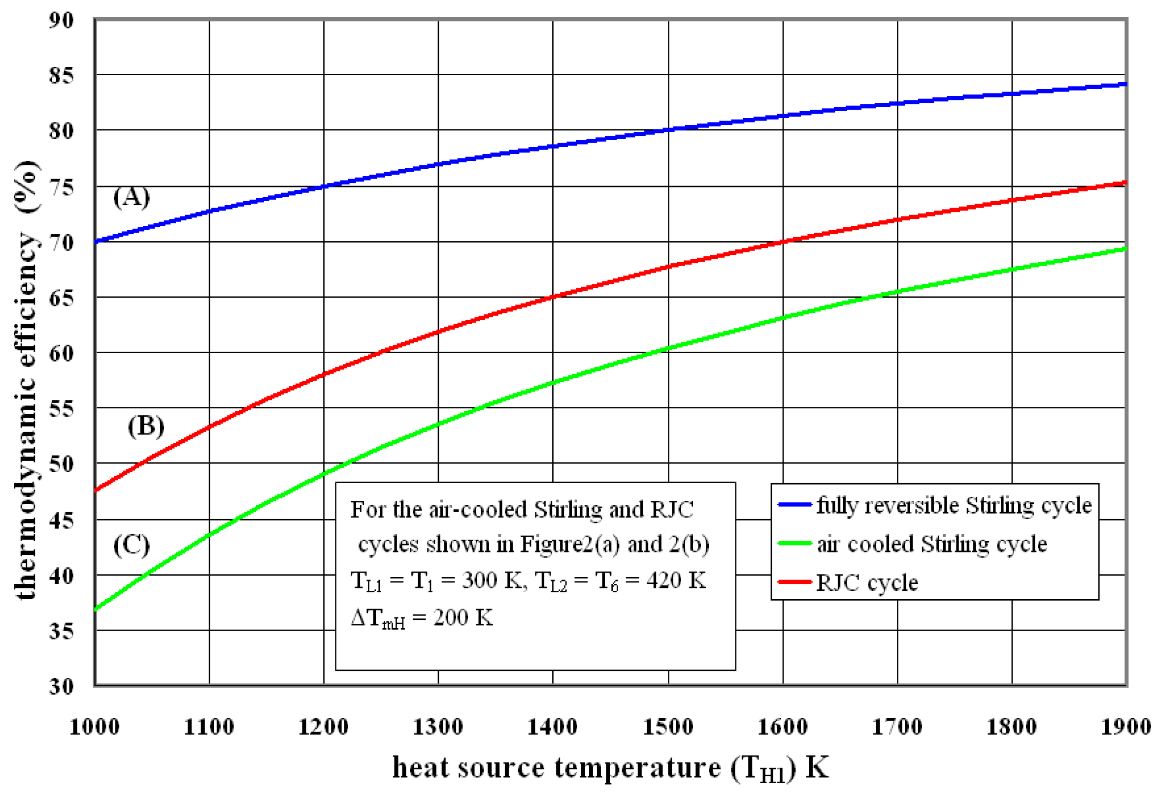
For the purpose of analysis the ambient air temperature is assumed to be 300 K.
In order to compare the thermodynamic efficiencies of otherwise internally reversible RJC and SC engines with finite-time heat transfer it is necessary to define a suitable temperature difference between the heat sources and the engine. For heat exchangers there are two well know temperature differences that might be used: Approach-temperature-difference (ATD) and log-mean or area-weighted-temperature-difference (∆Tm). The following analysis shows equal values of ∆Tm probably gives the fairest comparison but the difference appears not to be significant to the conclusion reached. ATD and ∆Tm are related by:
Q = C min ε ATD = UA Δ T m
where the minimum capacity rate of the hot and cold streams, Cmin = ( m C p ) min .

3.1. Comparison of Efficiency Based on Equal ∆Tm,H Values

Figure 3a,b show the variation in temperature through the high-temperature heaters of the RJC and SC engines. Defining the number-of-heat-transfer units as N T U = U A C min , from Equation (2) it may be shown:
ATD = NTU ε Δ T m
For the RJC air heater, shown in Figure 3a, assuming the heat capacity rates (C) of both hot and cold streams are equal (Cmin = Cmax) then heat exchanger effectiveness (εRJC) is be given by:
ε R J C = N T U N T U + 1
For the SC heater, the cold stream of which is isothermal, then heat exchanger effectiveness is given by:
ε S C = 1 exp ( N T U )
Figure 4 shows the variation in ε with NTU (number of heat transfer units) for both engine’s high-temperature heat exchangers.
If it is assumed that the NTU and ∆Tm values are the same for both cycles. Assuming NTU = 1.5 then from Figure 4, or by substitution in to Equations (4) and (5), the heat-exchanger-effectiveness values for the RJC and SC heaters are 0.6 and 0.78. If we assume an equal ∆Tm,H value of 200 K and an NTU value of 1.5 in both cases then from Equation (2), ATDSC = 386 K, ATDRJC = 500 K. In other words, if the flue-gas temperature at the outlet of both engine heaters has the same value, the temperature of the SC engine expander inlet temperature, Te, will be greater than that of the RJC engine heater air entry temperature, T3 in Figure 3a. This appears to offer advantages for the performance of the SC engine. However, because the flue-gas temperature felt by the SC expander flow increases as it moves from left-to-right in Figure 3b the exergy loss is larger than in the case of the RJC engine heater, in which the temperature of the air stream increases as it flows the heater.
If the flue-gas temperature at entry to the high-temperature heat exchanger is assumed to be 1400 K then referring to the heat exchange process described in from Figure 3a:
T 4 = T H 1 Δ T m , H = 1400 200 = 1200   K
and T 3 = T H 1 ATD = 1400 500 = 900   K .
Therefore, T H 2 = T 3 + Δ T m , H = 900 + 200 = 1100   K
Referring to Figure 3b, for the SC engine the ∆Tm,H is given by:
Δ T m , H = ( T H 1 T H 2 ) I n ( T H 1 T e T H 2 T e )
Solving the above for Te gives:
T e = exp ( T H 1 T H 2 Δ T m , H ) T H 2 T H 1 exp ( T H 1 T H 2 Δ T m , H ) 1
As the heat rate (QH) and the capacity rate (Cmin) are assumed to be equal those of the RJC engine then by substituting known results in to Equation (6) gives:
T e = exp ( 1400 1100 200 ) 1100 1400 exp ( 1400 1100 200 ) 1 = 1013.8   K
According to Rogers et al. [15] the thermodynamic efficiency of the internally reversible RJC engine is given:
η t h , R J C = 1 α θ R J C *
Given that T4 = 1200 K and assuming an ambient temperature of 300 K then the cycle temperature ratio, (T4/T1) = θ R J C * = 4 . From Equation (7) it is clear that the thermodynamic efficiency of the ideal RJC engine approaches that of a Carnot engine with the same cycle temperature ratio as α approaches unity, and in fact becomes for practical purposes the RJC engine equates to an Atkinson cycle. However, in order to permit a fair comparison between the Stirling cycle and the RJC it is necessary to assign a practical value to α in order to solve to Equation (7). By following a analysis described by Goodger [16], and by assuming reasonable component efficiencies for the expander (85%), compressor (75%) and recuperator (80%), it can be shown that α = 1.4 gives the optimum thermodynamic efficiency when θ R J C * = 4. The assignment of process irreversibilities to the RJC calculation of course is against the first assumption list above that both cycles are internally reversible. However, not to do so would place the RJC at a clear advantage. Then, for present case the thermodynamic efficiency for an externally heated, internally reversible RJC engine is given by:
η t h , R J C = 1 1.4 4. = 0.65 or 65 %
According to Wright-Barker [17], the thermodynamic efficiency of the internally reversible SC engine is given by:
η t h , S C = 1 1 θ S C *
where θ SC * = T e T c .
To solve Equation (8) and to provide a fair comparison between the RJC and the SC engines is assumed that the SC engine is air cooled and TL1 in Figure 5 equals to an ambient air temperature (Tamb) of 300 K, which equals T1 in Figure 2a. Furthermore, if both engines were used to power a CHP systems it would be fair to assume that TL2 should equal the air temperature recuperator outlet, T6 in Figure 2a, which in this case equals the compressor air discharge temperature, T2 in the same diagram, which for a value of α of 1.4, TL2 = T6 = T2 = 1.4 × 300 = 420 K.
Assuming that TC = TL2:
η t h , S C = 1 420 1013.8 = 0.58 or 58 %
Because TC must in practice be greater 420 K and TL1 then the thermodynamic efficiency of the SC engine would be less than the 58% calculated. In order for an internally reversible SC engine to equal that of an internally reversible RJC engine then the value of TC would have to be reduced to 354 K (82 °C), which in practice may compromise the use of such an engine in a CHP system and require a significant increase in coolant flow (approximately 220% increase) with an associated increase pump/fan power requirement. An alternative to assuming both engines have the same high-temperature heater ∆Tm,H value is to assume that the ATDH are equal.

3.2. Comparison of Efficiency Based on Equal ATDH Values

From Equation (2), if the heat rates, QH, are to be the same for both engines and ATDH and Cmin are also equal then also the heat exchanger effectiveness values, εH must be equal. Rearranging Equation (2) gives:
Δ T m , H = A T D ε N T U
Therefore, in this case the NTU values for each engine cycle cannot be equal. Solving Equations (4) and (5) for NTU then for the RJC engine heater:
N T U R J C = ε R J C 1 ε R J C
and, for the Stirling cycle heater:
NTU SC = L n ( 1 ε SC )
Assuming an economic heat exchanger effectiveness value of 0.7 then NTURJC = 2.33 and NTUSC = 1.2. If the heat source temperature, TH1, of 1400 K is again assumed and with an equal approach temperature difference, ATDH, of 500 K then:
Δ T m , H , RJC = 500 0.7 2.33 = 150   K ,   Δ T m , H , SC = 500 0.7 1.2 = 292   K
Therefore, for the RJC engine heater, with Cmin = Cmax:
Δ T m , H , R J C = T H 1 T 4
Therefore, T4 = 1400 − 150 = 1250 K and the RJC cycle temperature ratio:
θ R J C * = 1250 / 300 = 4.166
Assuming a compressor isentropic temperature ratio, ε, of 1.4 as used previously then:
η t h , R J C = 1 α θ R J C * = 1 1.4 4.166 = 0.66 or 66 %
For the SC engine heater:
T e = exp ( T H 1 T H 2 Δ T m , H ) T H 2 T H 1 exp ( T H 1 T H 2 Δ T m , H ) 1
Inserting values gives:
T e = exp ( 1400 1100 292 ) 1100 1400 exp ( 1400 1100 292 ) 1 = 933   K
Assuming the same low-temperature heat exchanger temperature as previously calculated:
Tc = 420 K the thermodynamic efficiency of the internally reversible SC engine is,
η th , St = 1 420 933 = 0.0.55 or 55 %
A conclusion at this point must be that due to finite-time heat transfer the internally reversible RJC engine has potentially a higher thermodynamic efficiency than the equivalent SC engine regardless of whether the comparison is carried out with equal ATDH or ∆Tm,H values at the air heater.

3.3. Some Results and Discussion

Subject to the assumptions 1 to 10 previously listed, the results given in the previous example calculation show that the thermodynamic efficiency of the RJC cycle is about 10% more efficient than the Stirling cycle whether or not the heat is assumed to be added with either equal ∆Tm,H or ATDH value.
Calculations described in Section 3.2 were repeated over a range of heat source temperatures and the results are shown in Figure 6. This data, based on an equal ∆Tm,H for the finite-time heat transfer calculations, show the variation in thermodynamic efficiency for both RJC and Stirling cycle engines. Curve A in gives the variation in thermodynamic efficiency for a fully-reversible Stirling engine whilst Curve C gives the results for an internally-reversible Stirling engine with finite-time heat transfer. The effect of finite-time heat transfer on thermodynamic efficiency is clearly seen from the results. What is interesting in the present case are the comparative results in between the internally-reversible RJC engine with finite-time heat transfer (Curve B) and the Stirling engine (Curve C). These data show that the thermodynamic efficiency of the RJC engine is more efficient than an air cooled Stirling cycle engine over the range of heat source temperatures investigated.
The results indicate that when heat is supplied at the same maximum temperature, TH1, to internally-reversible cycles, and the heat source is of a variable temperature type, then the thermodynamic efficiency of the RJC is greater than that of the Stirling engine when this is cooled by ambient air which is then used for heating purposes. This result may be useful in the design of heat engines for small-scale CHP applications. A limitation to the application of reciprocating RJC engines may be their low imep, which in turn increases the physical size of an engine for a given power. However, if an engine is required to supply small amounts of powers for domestic or light commercial applications this should not be a barrier. Also, by using multi-stage compression with inter-stage cooling it is possible to increase network output, but at greater capital expense introduced by the need for additional heat exchangers. Similar arguments may be put forward for inducing muli-stage expansion with inter-stage reheating. A detailed analysis of the effects on performance and particularly imep of multi-stage expansion and compression lies outside the scope of the article, however, the pros and cons of multi-staging processes are discussed in most standard text book of which Rogers and Mayhew [8] and Googer [16] are but two.

4. Conclusions

The micro or small-scale CHP systems based on IC engine technology are invariably four-stroke Otto cycle machines with thermal electrical efficiencies of about 30%. The use of well-developed vehicle engine technology to power CHP systems is believed to have an initial-cost advantage at this time; however, IC engines are limited to burning highly refined fuels, such as petroleum, LPG or natural-gas.
External combustion engine types, such as the Stirling, Ericsson or Rankine cycle machines, can run on almost and mix of low-grade fuel, such as wood pellets or low grade bio-oil. However, these closed-cycle machines have the disadvantage that they need to reject heat to the environment via a low-temperature heat exchanger and this both reduces their overall thermodynamic efficiency and increases their capital cost.
By comparing the relative performance of internally heated open cycle engines with externally heated closed cycle machines the authors conclude that an externally heated open cycle engine might offer the advantages of both types. To investigate this further the performance of an externally heated RJC engine was compared with that of an externally heated Stirling cycle engine, assuming a variable temperature heat source, equal source and sink temperatures and an air-cooled Stirling engine. As shown in Figure 6, the results show that an externally heated RJC engine has the potential for greater thermodynamic efficiency than the Stirling machine for the same heat source and sink temperatures when applied to a typical CHP system.

Author Contributions

This paper is based on an idea by Ian W Eames in the autumn of 2014 and developed by him, Kieran Evans and Stephen Pickering at Nottingham University. The aim was to investigate a range of heat engine cycles that might offer a practical solution to developing small-scale CHP and tri-generation systems powered by burning low-grade fuels common to the developing world. The subject had been of interest to the authors for several years. Ian W. Eames was the main author of the article and of the ideas behind the article: Kieran Evans carried out a detailed literature review of which a condensed version is included in this article and Stephen Pickering provided much useful advice and guidance on the direction of the project and this article.

Conflicts of Interest

The authors declare no conflict of interest.

Nomenclature

Aheat transfer area (m2)
ATDapproach temperature difference (K)
Cheat capacity rate = mCp (W/K)
CHPcombined heat and power
Cpspecific heat capacity at constant pressure (J/kg·K)
mmass flow (kg/s)
NTUnumber of heat transfer units
PrRJC cycle pressure ratio (−)
Qinputheat input rate (W)
RJCrecuperated Joule cycle
sspecific entropy (J/kg·K)
Ttemperature (K)
Tcisothermal compression temperature (K)
Teisothermal expansion temperature (K)
ΔTmarea-weighted (or log-mean) temperature difference (oC)
Uoverall heat transfer coefficient (W/m2·K)
Greek letters
αisentropic compression temperature ratio (−)
εheat exchange effectiveness (−)
θcycle temperature ratio, TH1/TL1 (−)
θ*cycle temperature ratio for an internally reversible engine
η c isentropic compression efficiency (−)
η e isentropic expansion efficiency (−)
η t h thermodynamic efficiency (−)
Subscripts
Ambambient air
SCStirling cycle
fgflue-gas
Hheat source temperature
H1heat source inlet temperature
Lheat sink temperature
L1heat sink inlet temperature
optoptimum value
rrecuperator
RJCrecuperated Joule cycle
SCStirling cycle

References

  1. Organ, A.J.; Finkelstein, T. Air Engines: The History, Science, and Reality of the Perfect Engine; ASME: New York, NY, USA, 2009. [Google Scholar]
  2. Cardozo, E.; Erlich, C.; Malmquist, A.; Alejo, L. Integration of a wood pellet burner and a Stirling engine to produce residential heat and power. Appl. Therm. Eng. 2014, 73, 671–680. [Google Scholar] [CrossRef]
  3. Conroy, G.; Duffy, A.; Ayompe, L.M. Economic, energy and GHG emissions performance evaluation of a WhisperGen Mk IV Stirling engine l-CHP unit in a domestic dwelling. Energy Convers. Manag. 2014, 81, 465–474. [Google Scholar] [CrossRef]
  4. Eckardt, D. Gas Turbine Powerhouse; De Gruyter Oldenbourg: Berlin, Germany, 2014. [Google Scholar]
  5. Joule, J.P. On Air-Engines; Report of the British Association: Manchester, UK, 19 June 1851. [Google Scholar]
  6. Brayton, G. Improvements in Gas-Engines. U.S. Patent 125166A, 2 April 1871. [Google Scholar]
  7. Moss, R.; Roskilly, A.; Nanda, S. Reciprocating Joule cycle engine for domestic CHP system. Appl. Energy 2005, 80, 169–185. [Google Scholar] [CrossRef]
  8. Rogers, G.; Mayhew, Y. Engineering Thermodynamics, 4th ed.; Longman Group Limited: London, UK, 1995. [Google Scholar]
  9. Lewitt, E.H. Thermodynamics Applied to Heat Engines, 5th ed.; Sir Isaac Pitman and Sons Limited: London, UK, 1953. [Google Scholar]
  10. AsjaGen. Available online: http://www.asjagen.com/totem-2 (accessed on 17 April 2015).
  11. Helec Ltd. Available online: http://helec.co.uk (accessed on 16 April 2015).
  12. Baxi Ltd. Available online: http://www.baxi.co.uk/renewables/combined-heat-and-power/ecogen.htm (accessed on 3 March 2015).
  13. Ecogen: The Baxi Ecogen Dual Energy System; Baxi Limited: Warwick, UK, 2010.
  14. Jones, O.; Wardle, R.; Matthews, P. Customer-Led Network Revolution—Micro-CHP Trial Report; Customer Network-Led Revolution report L086: London, UK, 17 November 2014. [Google Scholar]
  15. Cohen, H.; Rogers, G.F.C.; Saravanamuttoo, H.I.H. Gas Turbine Theory, 2nd ed.; Longman Group Limited: London, UK, 1972. [Google Scholar]
  16. Goodger, E.M. Principles of Engineering Thermodynamics; The Macmillan Press: London, UK, 1974. [Google Scholar]
  17. Wright-Baker, H. Inchley’s Theory of Heat Engines; Longmans, Green and Co Ltd.: London, UK, 1945. [Google Scholar]
Figure 1. (a) Schematic view of an externally heated RJC (recuperated joule cycle) engine; (b) An ideal RJC engine in a temperature-entropy co-ordinate diagram. State-points defined in Table 2.
Energies 09 00130 g001
Figure 2. Showing T-s diagrams for: (a) An internally ideal recuperated Joule cycle with external heat addition; (b) An externally heated and cooled ideal Stirling cycle.
Energies 09 00130 g002
Figure 3. (a) Variation in temperature through the RJC engine high-temperature heater; (b) Variation in temperature through the SC engine high-temperature heater.
Energies 09 00130 g003
Figure 4. Showing the variation in heat-exchanger-effectiveness (ε) with NTU for the hot-side heat exchangers of SC (in blue) and RJC (in red) engines.
Energies 09 00130 g004
Figure 5. Showing the variations in working fluid and coolant air temperatures through the low-temperature heat exchanger of the internally reversible Stirling cycle engine.
Energies 09 00130 g005
Figure 6. Showing a comparison between the thermodynamic efficiencies of: (A) Fully reversible; (B) RJC engine as described in Figure 2a; (C) Air cooled SC engine, as described in Figure 2b for an equal value of ∆Tm,H.
Energies 09 00130 g006
Table 1. A comparison between the thermodynamic efficiencies of open-cycle Otto and closed-cycle Stirling engines.
ManufacturerSystem NameEngine CycleOutputThermo EfficiencyReference
asjaGenTOTEM 10Otto10 kW30%[10]
Helec LtdEnergimizerOtto7.5 kW25%[11]
Helec LtdPowerbox 7500QSEStirling7.5 kW18%[12]
Baxi LtdEcogenStirling1 kW13%[12,13,14]
Table 2. Processes shown in Figure 2.
State-PointsProcess
1–2Compression of ambient air
2–3Recuperative heating
3–4External heating
4–5Expansion
5–6Recuperative cooling

