Abstract
A novel tuned heave plate energy-harvesting system (THPEH) is presented for the motion suppressing and energy harvesting of a semi-submersible platform. This THPEH system is designed based on the principle of a tuned mass damper (TMD) and is composed of spring supports, a power take-off system (PTO) and four movable heave plates. The permanent magnet linear generators (PMLG) are used as the PTO system in this design. A semi-submersible platform operating in the South China Sea is selected as the research subject for investigating the effects of the THPEH system on motion reduction and harvesting energy through numerical simulations. The numerical model of the platform and the THPEH system, which was established based on hydrodynamic analysis, is modified and validated by the results of the flume test of a 1:70 scale model. The effects of the parameters, including the size, the frequency ratio and the damping ratio of the THPEH system, are systematically investigated. The results show that this THPEH system, with proper parameters, could significantly reduce the motions of the semi-submersible platform and generate considerable power under different wave conditions.
1. Introduction
Powerful waves are harmful to ocean structures but also have the great potential to provide clean energy at the same time. Utilizing this powerful renewable energy and protecting our structures at the same time is a meaningful and interesting topic.
Although wave energy converters are still far from commercial use, with the development of energy harvesting technologies, especially the improvement of the permanent magnet linear generator, wave energy converters (WEC) employing PMLG as the PTO system have emerged in applications and research studies [1,2,3]. For deep water utilization, whose energy flux densities are much larger compared to near shore sites, multi-body floating WECs such as Wavebob [4] and IPS Buoy [5] have been systematically studied during the most recent decade. Nevertheless, building a power grid for transmitting the electronic power from a deep-water site would significantly increase the total cost of wave power. If the power generated by deep-water WECs is directly supplied for the operation of deep-water platforms, whose energy supply from the shore is difficult and expensive, it will make the WECs’ future brighter.
Semi-submersible platforms are considered to be the earliest type and most widely used deep water platform for oil and gas exploration because of their large deck area and payload capacities. However, because of the small water plane area and the draft, the motions of semi-submersibles, especially heave motion, are much larger than other deep-water platforms such as Spars and the tension leg platforms (TLP). To improve the performance of semi-submersible platforms, many scholars have concentrated their efforts on inventing novel type semi-submersibles [6,7,8,9]. These concepts for improving the semi-submersible platform could be summarized as having a deeper draft, installing heave plates and using truss columns instead of conventional columns.
In the author’s opinion, the best solution is converting the kinetic energy of the platform into electronic power, which would make the operation more safe and economical. The tuned mass damper (TMD) is an effective way for the vibration control of structures and has been fully developed since Frahm [10] proposed the first tuned mass damper in his patent in 1911. Since then, many adaptive, semi-active and active methods for improving the performance of the TMD have been developed [11,12,13] and realized in practical engineering projects [14,15,16]. The dampers are adapted in conventional TMDs, and the energy absorbed by a TMD system is converted to heat and dissipated in the damper. Recently, the absorbed energy could be converted into electrical power by different generators or the use of piezoelectric materials [17,18,19] applied in the TMD system.
For reducing the heave motion of the semi-submersible platform, a novel tuned heave plate system was proposed by Kun Liu [20] and Hang Zhu [21] based on the same idea as the TMD. Compared to the traditional heave plate system, the plate is connected to the platform by spring and damping elements. In this way, the tuned heave plate system could be tuned to a certain period in order to achieve better control than a traditional fixed heave plate. In this paper, four movable heave plates are installed beneath the columns to control not only the heave motion but also the roll and pitch motions. The damping elements of the tuned heave plate system are replaced by PMLGs, and this tuned heave plate energy-harvesting system (THPEH) could not only suppress the motions of the platform but also produce power for the platform’s operation at the same time.
In this paper, the effectiveness of the THPEH system with different parameters under different wave conditions is investigated systematically. First, the numerical model of the semi-submersible platform with the THPEH system is built in the Matlab & Simulink module. Second, the numerical model of the semi-submersible platform is modified and verified by testing a 1:70 scale model in a wave tank. Third, the parameter studies of the size, the tuned period ratio and the damping ratio of the THPEH system are carried out. Finally, the performances of the semi-submersible platform with the designed THPEH system under different waves are illustrated and analyzed. The results show that the THPEH system could significantly reduce motions and generate considerable power at the same time.
2. Conceptual Design of the Tuned Heave Plate Energy Harvesting System
The illustration of the THPEH system installed on the semi-submersible platform and the details of the THPEH system are shown in Figure 1. Figure 1a shows the conceptual design of a semi-submersible with the tuned heave plate system. The THPEH system is composed of four truss-plate structures located under the columns. The plate below the pontoon is installed deep enough to avoid the wave exciting force. Figure 1b shows an illustration of a truss-plate structure. The permanent magnet linear generator is used and is placed on the top of the truss tube in the platform pontoon. Figure 1c illustrates the connection structure of the heave plate and the truss structure. The connection only allows the heave plate move along the vertical truss tube. The stator coil and iron are rigidly connected to the outer tube on the heave plate, and the tube wrapped by the permanent-magnets extended from the truss structure can move through the stator and the outer tube on the plate. This PMLG can harvest the related motion energy into electrical power. The spring support is placed between the truss tube and the heave plate, which determines the natural period of the THPEH system.
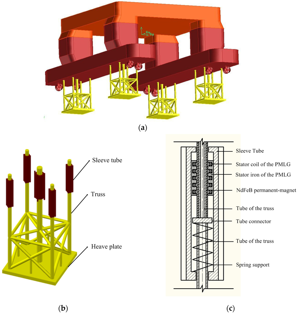
Figure 1.
(a) The illustration of the semi-submersible platform with the tuned heave plate energy harvesting system; (b) the illustration of a truss-plate structure of the THPEH system; (c) the diagram of the connection structure in the sleeve tube.
Figure 1.
(a) The illustration of the semi-submersible platform with the tuned heave plate energy harvesting system; (b) the illustration of a truss-plate structure of the THPEH system; (c) the diagram of the connection structure in the sleeve tube.

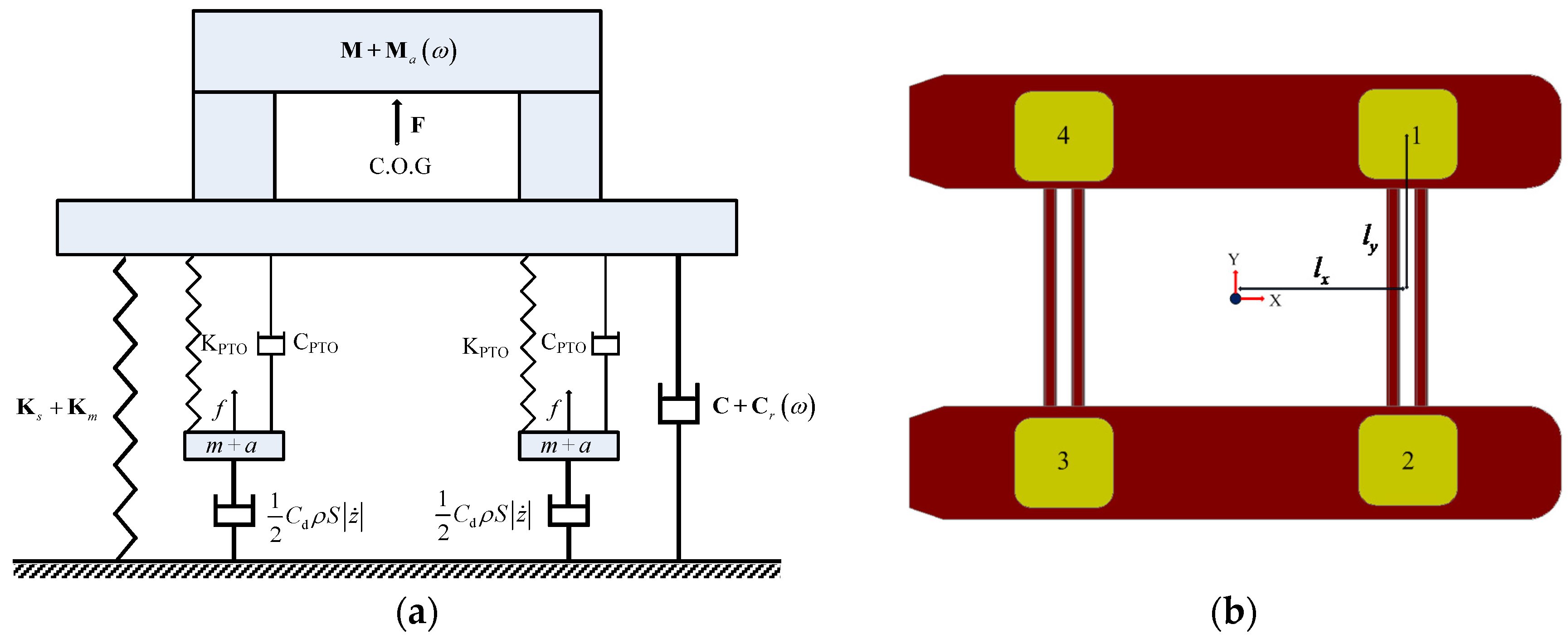
Assuming the force of PMLG is a linear damping force, Figure 2a shows the mechanical model diagram of the semi-submersible platform with the THPEH system in heave motion. The whole system of the spring supports and PMLGs are the power take-off system (PTO) in this model. The plane layout of the plates is shown in Figure 2b. Under the small motion assumption, the motion of the THPEH system is governed by Equation (1).
where , , , and are the matrices of the mass, added mass, the drag coefficient and wave exciting force of the heave plates of the THPEH system, respectively; , and are the heave displacement vector, velocity vector and acceleration vector of the four plates of the THPEH system; and are the damping coefficient and stiffness coefficient of the THPEH provided by the PMLGs and spring supports, respectively. is the density of sea water; is the area of the plate; and are the displacement transformation matrices of the THPEH system, defined by
where and are the distances between the centers of the platform and the plates along the x-axis and y-axis, respectively.

Figure 2.
(a) The mechanical model diagram of the semi-submersible platform with the THPEH system; (b) The horizontal arrangement and serial number of the plates in the THPEH system.
Figure 2.
(a) The mechanical model diagram of the semi-submersible platform with the THPEH system; (b) The horizontal arrangement and serial number of the plates in the THPEH system.
The second item on the right side of the Equation (1) is the force of the PTO system act on the THPEH system, and it is the interaction force between the THPEH system and the semi-submersible platform. In this way, the motion of the semi-submersible platform is governed by Equation (3).
where , are the matrices of the mass and the added mass of the platform and respectively. , , , and are the matrices of the radiation damping, viscous damping, stationary water stiffness and wave exciting force of the semi-submersible platform, respectively; is the six-DOF displacement vector of the platform. The force of the mooring system is accounted for in an equivalent linear stiffness matrix . is the mass contributed by the THPEH system
where is the mass of the heave plate, is the distance between the heave plate and the C.O.G of the platform. The second item on the right side of the Equation (3) is the force of the PTO system act on the semi-submersible platform system, defined as the control force
3. Numerical Model of the Semi-Submersible with the THPEH System
3.1. The State-Space Model for Radiation Damping Force Calculation
The added mass and radiation damping coefficients are relative to the motion frequency. A convolution calculation method is introduced to calculate the radiation force of the platform [22]. The radiation force of the semi-submersible is composed of two parts:
Introducing the impulse response function for calculating the radiation forces in the time domain gives
Therefore, the radiation force can be expressed as a convolution function of the velocity of the platform:
Additionally, the convolution calculation could be replaced by a linear system whose inputs are the velocities and outputs are the convolution parts of the radiation forces, and the linear system in the state-space model is an auxiliary state vector for convolution [23].
where , , , and are the system matrices, and is an auxiliary state vector for calculation. is the convolution part of the radiation force:
3.2. The State-Space Model for the Platform with the THPEH System
The motion Equation of the semi-submersible platform could be transformed to the state-space Equation as
where the state vector is
By introducing the model of the radiation force model, the system matrices and are
The displacements and velocities are set as the outputs, so the output matrices can be built as
According to the motion Equation, Equation (1), the state-space model of the heave plate motion is
where
The plates are assumed to be placed deep enough to ignore the wave exciting force on the plates. To output the velocity of the plates, the output matrices are constructed as
3.3. The Simulink Model for the Platform with the THPEH System
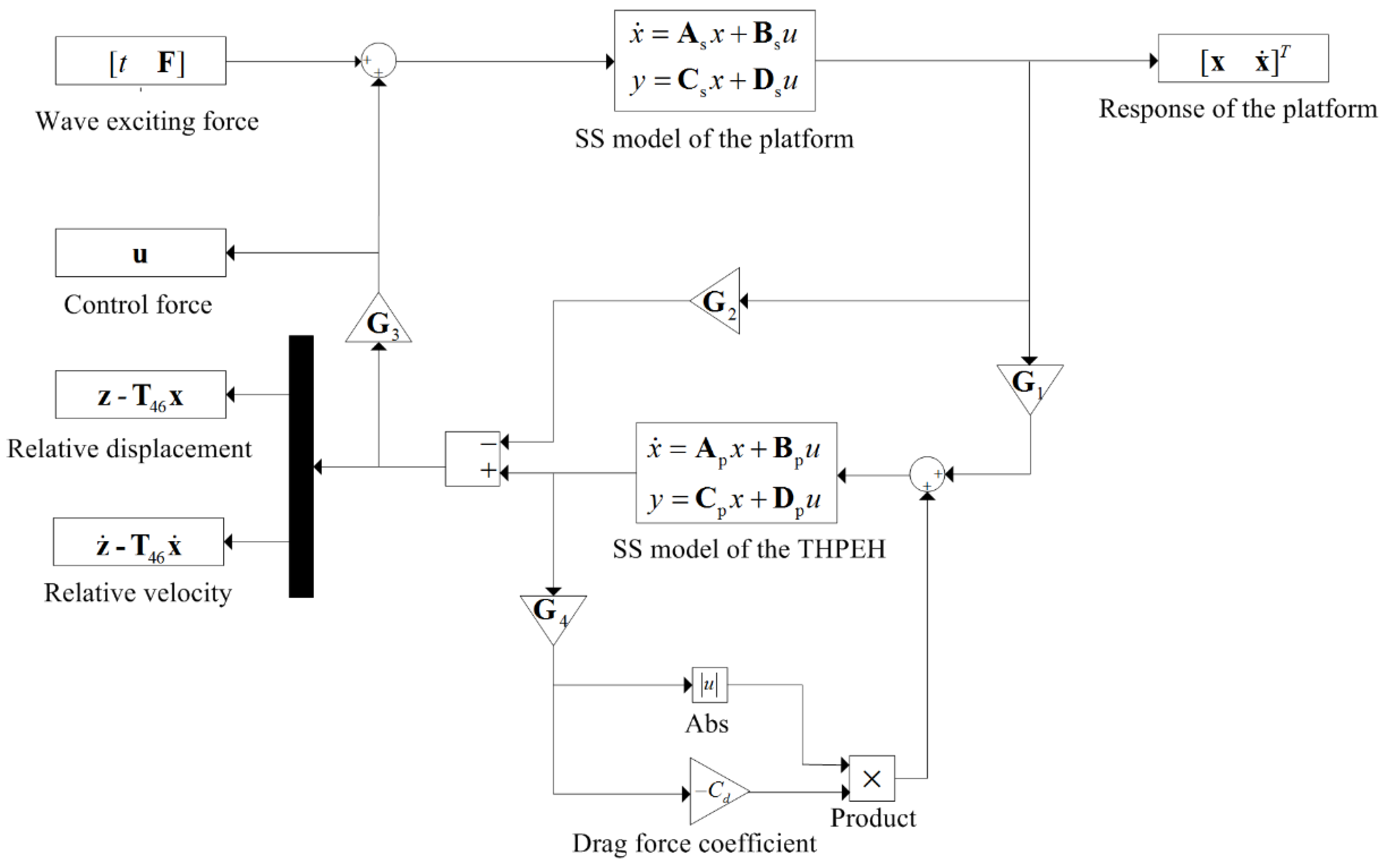
According to Equations (11) and (15), the state-space model of the semi-submersible and THPEH system, the diagram of the Simulink model, for calculating the performance of the system is shown in Figure 3. In addition, four gain matrices , , and are introduced to establish the calculation model in Simulink for the state-space model of the platform with the THPEH system.
In this way, the control force, relative displacements and velocities of the THPEH system are outputted.
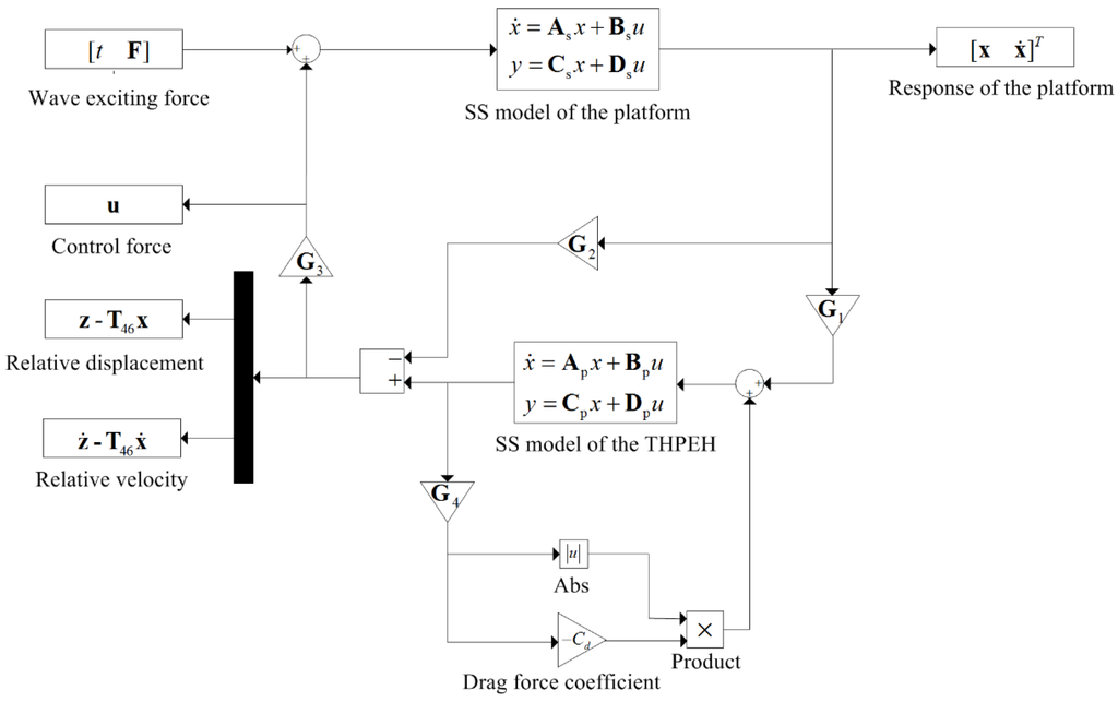
Figure 3.
The diagram of the numerical model of the semi-submersible platform in the Simulink module.
Figure 3.
The diagram of the numerical model of the semi-submersible platform in the Simulink module.
4. Wave Tank Tests for Semi-Platform Numerical Model Modification and Validation
4.1. Hydrodynamic Analysis of the Platform
For the semi-submersible platform, the panel model of the platform is established in AQWA software, as shown in Figure 4. Fifty regular waves uniformly distributed in the frequency interval 0.1 rad/s~1.2 rad/s are adopted for the hydrodynamic parameter analysis. Only the hydrodynamic parameters of the heave degree of freedom in the frequency domain are given in Figure 5 because of limited space.

Figure 4.
The panel model of the semi-submersible platform for boundary element method (BEM) calculation in AQWA software.
Figure 4.
The panel model of the semi-submersible platform for boundary element method (BEM) calculation in AQWA software.
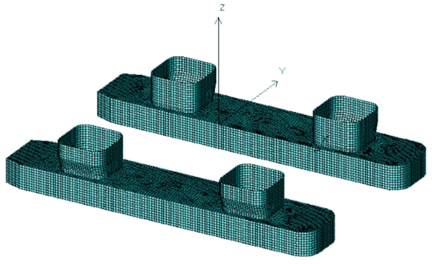
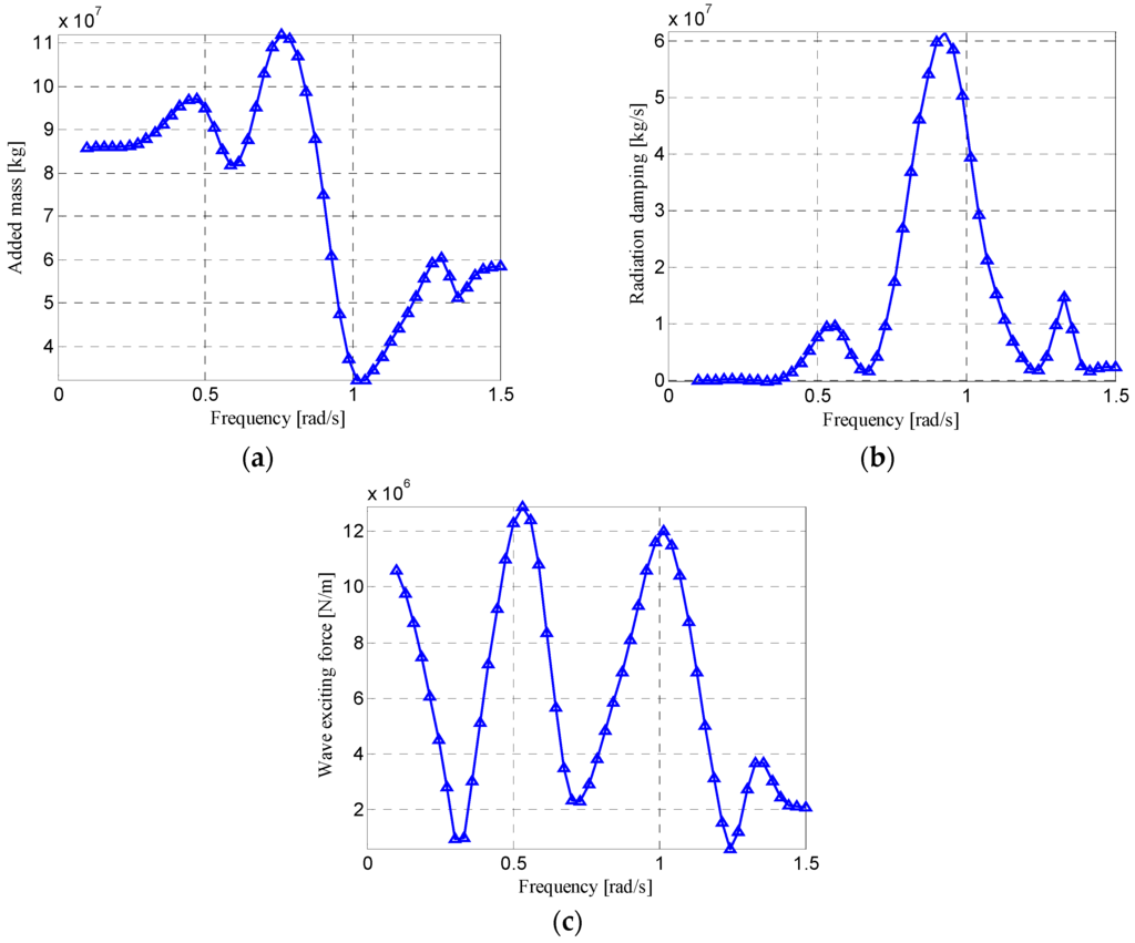
Figure 5.
(a) Added mass coefficients of the semi-submersible platform in the heave motion direction; (b) radiation damping coefficients of the semi-submersible platform in the heave motion direction; (c) wave exciting force amplitudes of the semi-submersible platform under 1 meter amplitude regular waves in the heave motion direction.

However, the heave plate is widely used in deep ocean structures for bringing large damping and added mass to the structure compared to its small volume. As the viscous effects are prominent because of its small thickness, the drag force of the Morison Equation is adapted for the heave plate’s radiation force. The drag force coefficient of the heave plates of different shapes have been studied both numerically [24] and experimentally [25,26] in the past decade. The drag coefficient of the heave plate is related to the KC number and the motion frequency. For a solid square heave plate, when the KC number is between 0.2 and 0.4, the frequency is between 0.1 and 0.5 Hz, and the drag coefficient is approximately 5~10. In this paper, the drag coefficient is taken as 8. For the added mass calculation, the fitting Equation from the results of Prislin’s experiment is adopted in this study [27].
4.2. Introduction of the Experiment Setup
Because the viscous effects are ignored in the hydrodynamic analysis, a viscous damping matrix should be introduced to the numerical model of the semi-submersible platform to consider the effects. The free-decay tests of the scale model are adopted to identify the viscous damping coefficients.
In this study, a 1:70 scale model of the semi-submersible platform is constructed for the flume tests. The specifications of the prototype and the model are shown in Table 1. According to the Froude similarity criterion, the force scale and the time scale are and , respectively. The tests were carried out in the nonlinear flume water tank in the state key laboratory of coastal and offshore engineering of Dalian University of Technology. The pictures of the experimental model and the wave tank are shown in Figure 6 and Figure 7. The arrangement of the test is illustrated in Figure 8. The wave tank is 60 meters long and 5 meters wide, and the maximum water depth is 2 meters. A piston wave-maker is located at one end of the tank, and the wave absorber is on the other end. The model of the platform is located in the central part of the tank. Two cameras are used to capture the six degrees of freedom (DOF) motion of the platform, and tension sensors are employed to monitor the tension of the mooring system. A taut truncated mooring system is designed to provide the total horizontal restoring stiffness as a deep-water mooring system. The mooring line is set up with steel wire and a spring to achieve this goal.

Table 1.
The physical parameters of the prototype and scale model of the semi-submersible.
| Parameters | Value | |
|---|---|---|
| Prototype | Model | |
| Deck (mm) | 77470 × 74380 × 8600 | 1107 × 1063 × 123 |
| Column (mm) | 17385 × 17385 × 21460 | 307 × 248 × 248 |
| Pontoon (mm) | 114070 × 20120 × 8540 | 1630 × 287 × 122 |
| Draft (mm) | 19,000 | 271 |
| Displacement (kg) | 5.17 × 10⁷ | 150.73 |
| Roll Radius of inertia (mm) | 33300 | 476 |
| Pitch Radius of inertia (mm) | 33400 | 477 |
| Yaw Radius of inertia (mm) | 35000 | 500 |

Figure 6.
The picture of the scale model of the semi-submersible platform.
Figure 6.
The picture of the scale model of the semi-submersible platform.
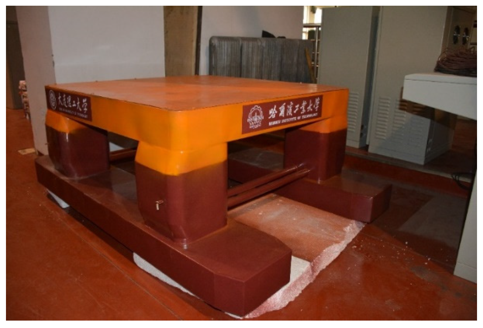
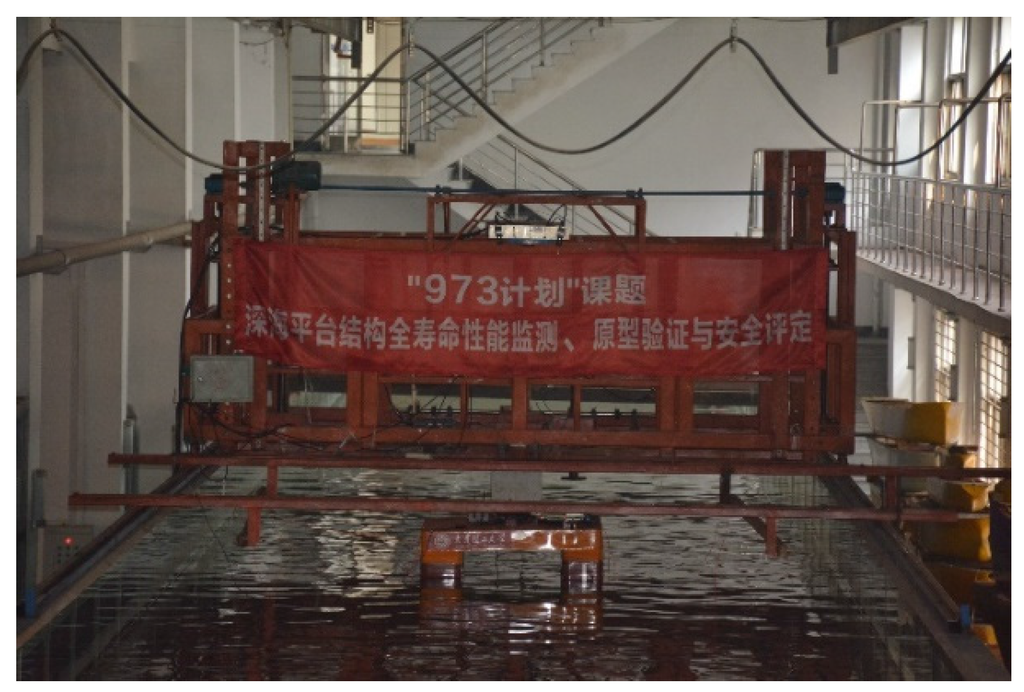
Figure 7.
The picture of the scale model in the wave tank.
Figure 7.
The picture of the scale model in the wave tank.

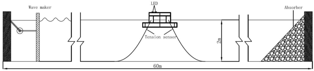
Figure 8.
The sketch of the layout of the wave tank tests of the semi-submersible platform.
Figure 8.
The sketch of the layout of the wave tank tests of the semi-submersible platform.

4.3. Free-Decay Tests for Damping Modification
The viscous damping of the platform could be identified according to the free decay test results because the viscous damping is predominant compared to the radiation damping in natural low frequency motion. The free decay tests for each DOF motion are carried out three times, and the logarithmic decrement ratio method is adopted to identify the damping ratio and natural period. The identified results of the scale model and the equivalent values for the full scale numerical model are shown in Table 2. The diagonal elements of the viscous damping matrix are estimated by
where and are the identification damping ratio and natural frequency for each DOF motion, respectively. As the stiffness of the platform in the horizontal plane was completely contributed to by the mooring system, the equivalent linear stiffness coefficients of the mooring system are calculated by
The time history curves of the numerical simulation and scale model in surge and pitch motion are shown in Figure 9. Notice that all of the experiment results in this paper are transformed into results for a full scale model.
Table 2.
The identification results of the natural period and the damping ratio in free-decay tests.
| Motion | Scale Model | Full Scale Numerical Model | ||
|---|---|---|---|---|
| Period (s) | Damping Ratio | Period (s) | Damping Ratio | |
| Surge | 32.32 | 6.05% | 270.41 | 6.05% |
| Sway | 42.40 | 6.06% | 280.74 | 6.06% |
| Heave | 2.44 | 4.48% | 20.41 | 4.48% |
| Roll | 7.26 | 6.70% | 60.74 | 6.70% |
| Pitch | 6.28 | 7.61% | 52.54 | 7.61% |
| Yaw | 42.8 | 8.64% | 358.09 | 8.64% |
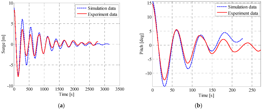
Figure 9.
(a) The comparison of the surge free-decay time histories of the modified numerical simulation and the wave tank test; (b) The comparison of the pitch free-decay time histories of the modified numerical simulation and the wave tank test.
Figure 9.
(a) The comparison of the surge free-decay time histories of the modified numerical simulation and the wave tank test; (b) The comparison of the pitch free-decay time histories of the modified numerical simulation and the wave tank test.

4.4. Numerical Model Validation by the Results of the Regular Wave Tests
To validate the veracity of the modified numerical model of the semi-submersible platform, the response amplitude operator (RAO) curves of the numerical model and the scale model are compared. For the scale model tests, considering the capacity of the wave-maker and the wave tank, 10 regular waves are designed for regular wave tests to obtain the RAO curves. The parameters of these regular waves are shown in the Table 3. For example, the experimental time history curves of the platform under the R2 in the 0 degree direction are shown in Figure 10. According to the RAO definition, the RAO is calculated as the ratio between the wave frequency motion amplitude and the wave height. However, the motions in the test contains the low frequency motion and wave frequency motion. As the ratio between the amplitude and STD value of the harmonic motion is . The wave frequency motion amplitude in experiment RAOs calculations is calculated in frequency domain as shown in Equation (21).
where, and are the wave frequency motion amplitude and response power spectrum on the DOF motion under the regular wave; and and are the frequency and amplitude of the regular wave; the frequency interval is designed to only cover the wave frequency motion in the frequency domain. In this study, they are defined as
The RAO curves of the numerical model and the experiment model are compared in Figure 11. The results indicate that the precision of the numerical model is acceptable, which indicates the similar trends of each DOF motion RAO curve, although there are still differences between two curves, especially the pitch motion under high-frequency waves.

Figure 10.
(a) Surge motion of the platform under the R2 in the 0 degree direction; (b) heave motion of the platform under the RW2 in the 0 degree direction; (c) pitch motion of the platform under the R1 in the 0 degree direction.
Figure 10.
(a) Surge motion of the platform under the R2 in the 0 degree direction; (b) heave motion of the platform under the RW2 in the 0 degree direction; (c) pitch motion of the platform under the R1 in the 0 degree direction.
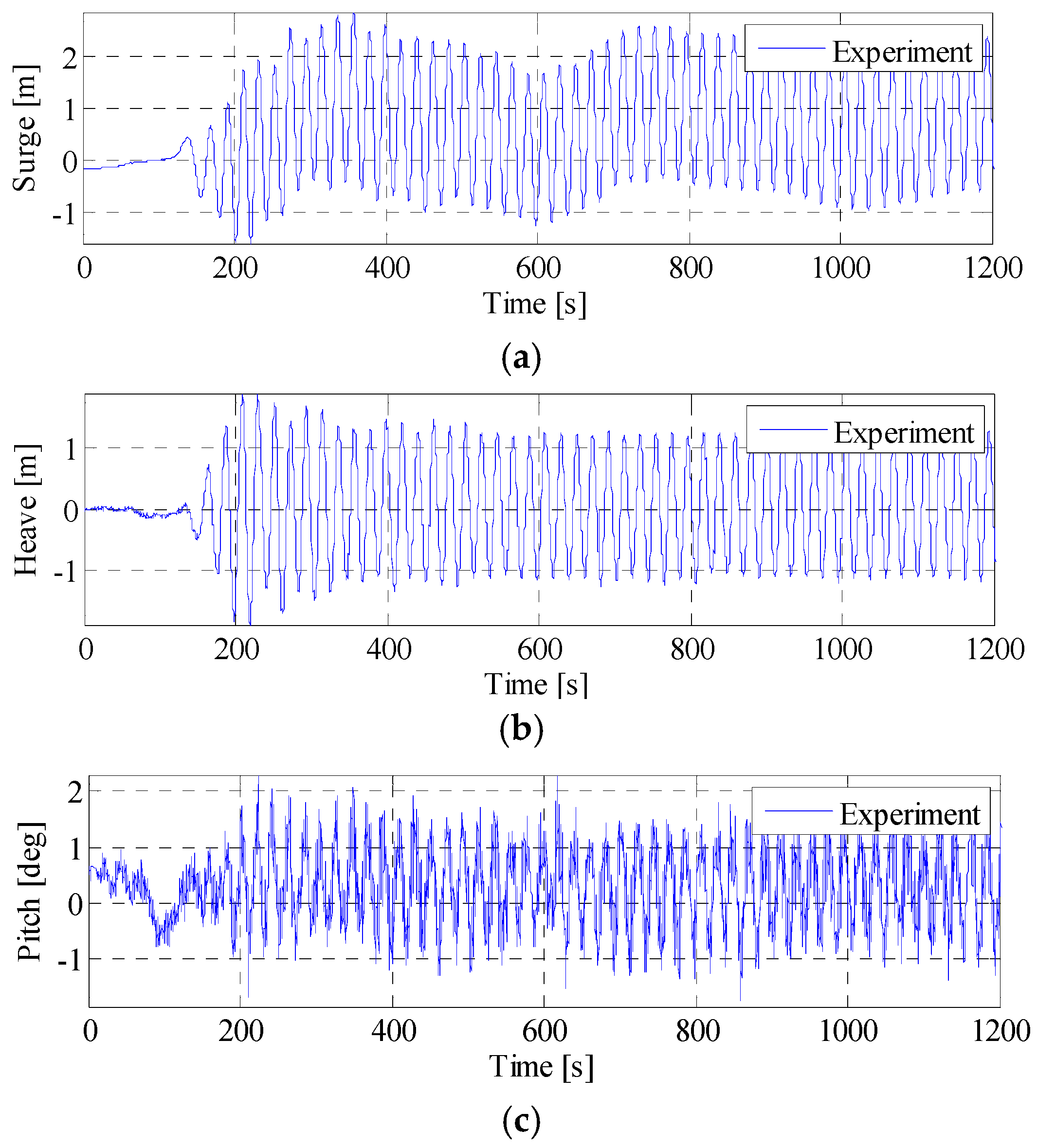
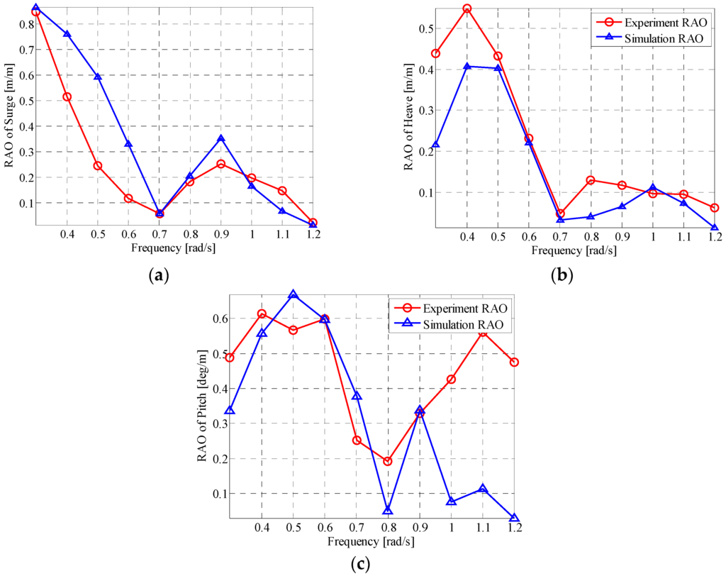
Figure 11.
(a) Surge RAO curves of the scale model test and numerical simulation of the platform; (b) heave RAO curves of the scale model test and numerical simulation of the platform; (c) pitch RAO curves of the scale model test and numerical simulation of the platform.
Figure 11.
(a) Surge RAO curves of the scale model test and numerical simulation of the platform; (b) heave RAO curves of the scale model test and numerical simulation of the platform; (c) pitch RAO curves of the scale model test and numerical simulation of the platform.
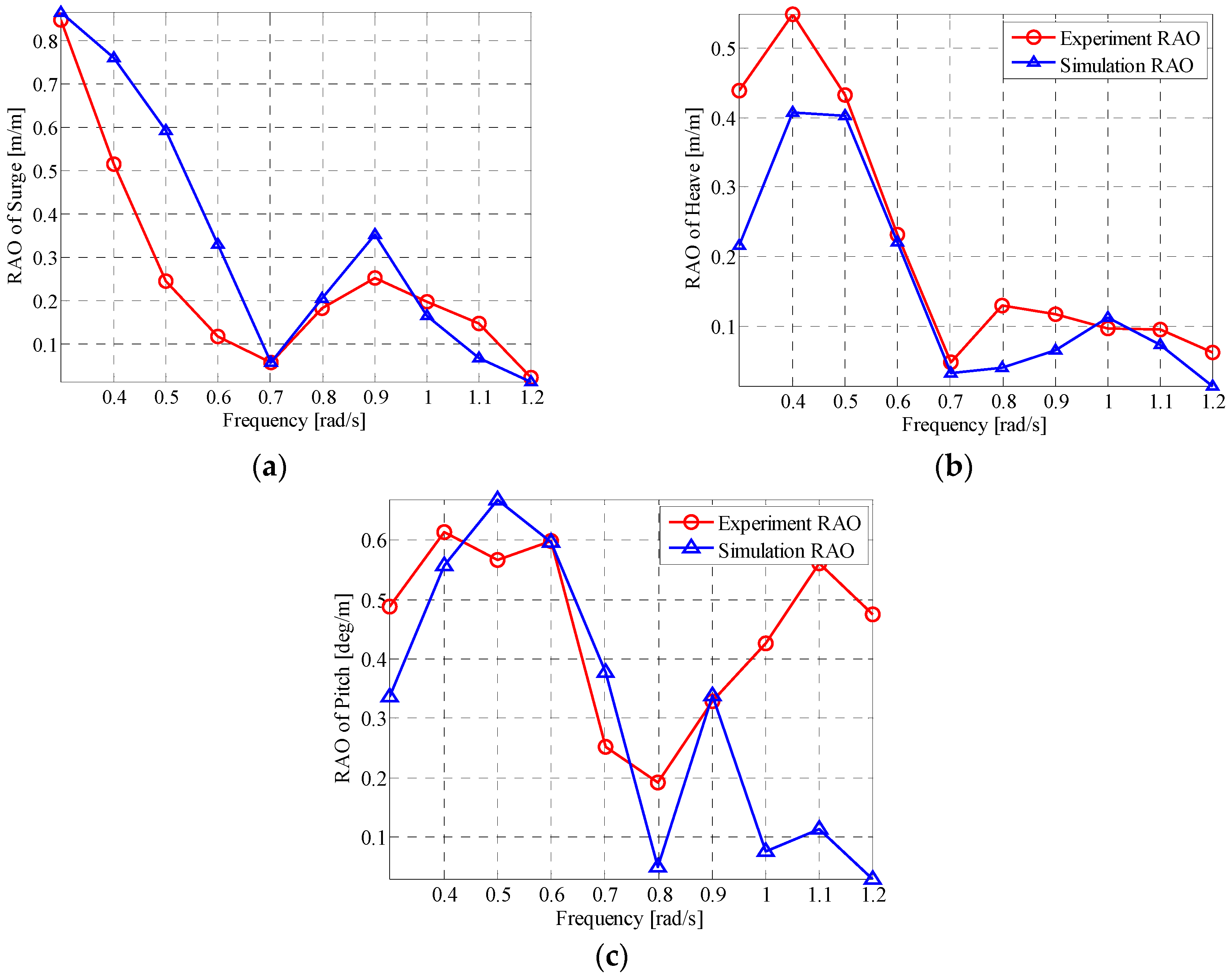
Table 3.
Regular wave parameters used in the tests.
| No. | The Real Wave States | The Aim Wave States in Tests | The Real Wave States in Tests | |||||
|---|---|---|---|---|---|---|---|---|
| Amplitude (mm) | Frequency (rad/s) | Period (s) | Amplitude (mm) | Frequency (rad/s) | Period (s) | Amplitude (mm) | Period (s) | |
| R1 | 3500 | 0.30 | 20.94 | 50.00 | 2.51 | 2.50 | 49.00 | 2.50 |
| R2 | 3500 | 0.40 | 15.71 | 50.00 | 3.35 | 1.88 | 50.00 | 1.88 |
| R3 | 3500 | 0.50 | 12.57 | 50.00 | 4.18 | 1.50 | 49.50 | 1.50 |
| R4 | 3500 | 0.60 | 10.47 | 50.00 | 5.02 | 1.25 | 49.30 | 1.25 |
| R5 | 3500 | 0.70 | 8.98 | 50.00 | 5.86 | 1.07 | 46.20 | 1.07 |
| R6 | 3500 | 0.80 | 7.85 | 50.00 | 6.69 | 0.94 | 50.30 | 0.94 |
| R7 | 3500 | 0.90 | 6.98 | 50.00 | 7.53 | 0.83 | 40.60 | 0.83 |
| R8 | 1400 | 1.00 | 6.28 | 20.00 | 8.37 | 0.75 | 16.90 | 0.75 |
| R9 | 1400 | 1.10 | 5.71 | 20.00 | 9.20 | 0.68 | 18.60 | 0.68 |
| R10 | 1400 | 1.20 | 5.24 | 20.00 | 10.04 | 0.63 | 21.60 | 0.63 |
5. Parameter Study of the THPEH System
Although the optimal parameters of the tuned mass damper for tall buildings has already been fully investigated [11], the parameter study of the THPEH is still needed to investigate the motion performances of the semi-submersible, which is quite different from tall buildings’ performance, and the environment loads. The key to designing the tuned heave plate system is to determine the size, tuned period and damping ratio of the THPEH system. The main aim of the THPEH system is reducing the motion of the platform. In this paper, as only the x-axis-direction wave is adopted, the motions in the surge, heave and pitch are considered in the study, and the motion reduction ratio is introduced to evaluate the performance of the THPEH system.
Where and are the motion of the platform with and without the THPEH system, respectively. The operator is the standard deviation calculation, and is the motion reduction ratio.
Another feature of the THPEH system is generating power, and the capture width is introduced to represent the energy absorption efficiency, which is already widely used in the wave energy field. The capture width is the ratio between the absorption power and the wave energy per wave front length of the incident wave. For irregular waves, the average wave energy power per wave front length is estimated by
where and are the peak period and the significant wave height of the irregular wave, respectively. The unit of is watt. Thereby, the capture width and the absorption power of the THPEH system are defined as
where is the capture width under irregular waves, and is the average capture power of the THPEH system under irregular waves, defined as
where is the relative velocity between the platform and plates.
In this parameter study, seven irregular wave conditions, including three extreme waves, two working wave conditions and two average conditions, in the Gulf of Mexico (GM), the South China Sea (SCS) and the North Sea (NS) are adopted to represent all of the wave conditions the platform may experience in its designed service life. These wave parameters are presented in Table 4. For each wave condition, a 3000-s-long history of the wave elevation is generated for the motion calculation. The wave exciting force of the platform includes 1st-order wave forces and 2nd-order wave forces and is calculated in AQWA. The modified numerical model in the last section is used for the numerical simulation. The wave exciting force on the THPEH system is ignored, assuming the heave plates are placed deeply enough. Sixteen different side lengths between 5 and 35 meters, 28 different tuned periods between 1 and 60 s and 28 different damping ratios between 1% and 60% are selected for this parameter study.
Table 4.
Characteristic wave parameters of seven irregular wave sea states.
| Wave Condition | (m) | (rad/s) | (s) | ||
|---|---|---|---|---|---|
| Name | Descriptions | ||||
| IRW-1 | 100-year in GM | 12.20 | 0.45 | 14.00 | 2.00 |
| IRW-2 | 100-year in SCS | 13.30 | 0.41 | 15.50 | 3.30 |
| IRW-3 | 10-year in SCS | 11.10 | 0.46 | 13.60 | 2.00 |
| IRW-4 | Working condition in GM | 3.96 | 0.70 | 9.00 | 2.00 |
| IRW-5 | Working condition in SCS | 6.00 | 0.56 | 11.20 | 2.00 |
| IRW-6 | Average condition in GM | 2.40 | 0.82 | 7.70 | 2.00 |
| IRW-7 | Average condition in NS | 1.88 | 0.86 | 7.28 | 2.00 |
5.1. Parameter Study of the Size of the Tuned Heave Plates in the THPEH System
The size of the heave plate determines the added mass of the THPEH system, which dominates the mass ratio between the THPEH and the platform. To investigate the effect of the heave plate’s size, for each size plate under each wave condition, the motion performance for different damping ratios and tuned periods are calculated. For every size of the plates, the maximum motion reduction ratio and maximum capture width under different wave conditions are selected to represent the optimal condition with this size of the plate. The optimal motion reduction ratio in the surge, heave and pitch motion and the capture width of the THPEH system with different sizes of the plate under seven wave conditions are shown in Figure 12.
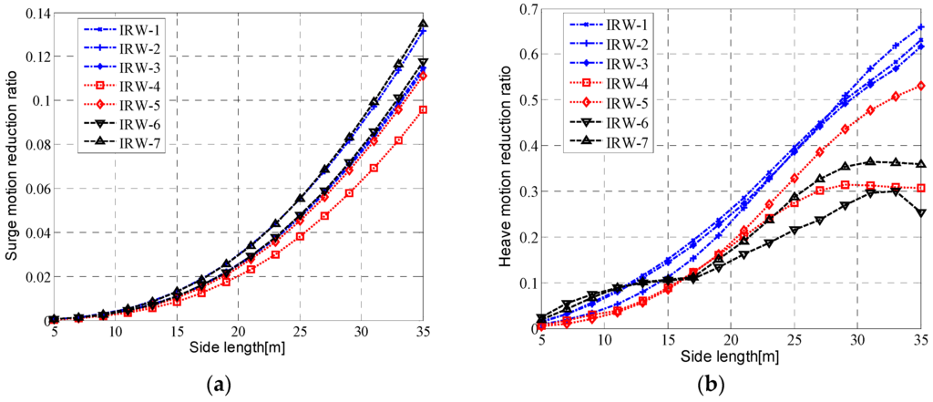

Figure 12.
(a) The surge motion reduction ratio with optimal connection parameters with different sizes of the plate; (b) the heave motion reduction ratio with optimal connection parameters with different sizes of the plate; (c) the pitch motion reduction ratio with optimal connection parameters with different sizes of the plate; (d) the capture width reduction ratio with optimal connection parameters with different sizes of the plate.

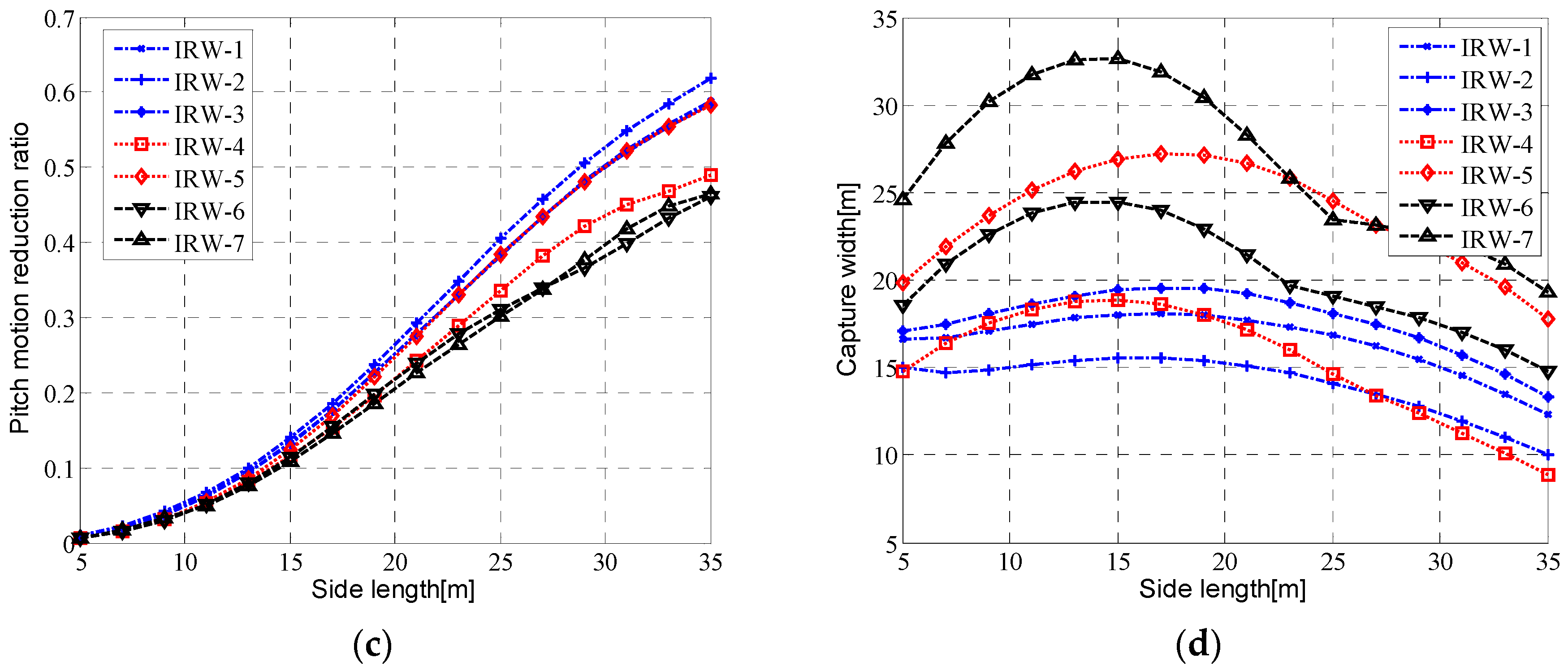
The result indicates that the reduction ratio for the three motions increases with the size of the THP plate for each sea state. However, for the capture width, there is an optimal size under each wave condition, and the optimal side lengths are distributed in the interval of 15–20 m. If motion reduction is adopted as the prime goal of the THPEH system, a large heave plate should be chosen. However, in this study, as the side of the column is 17 meters long, considering the installation and the efficiency of capturing power, the size of the heave plates in the THPEH system in paper is set to 17 meters long.
5.2. Parameter Study of the Tuned Period of the Tuned Heave Plate
Generally, the conventional TMDs used in tall buildings for suppressing the wind-induced vibration are tuned to the 1st-order natural frequency of the structure, as the natural frequency motion is dominated under wide-band frequency environment loads. However, compared to wind loads, the wave loads have a narrow band frequency, and the natural frequency of a well-designed semi-submersible platform for all motion is set far away from the peak frequency of waves. Especially for the heave motion of the semi-submersible platforms, the wave frequency motion is always dominated compared to the low frequency motion in the natural period. As a result, in order to achieve optimal control efficiency, the effect of the tuned period of the THPEH system needs to be investigated. The side length of the plates is set to 17 meters.
Figure 13 presents the contour maps of the heave motion reduction ratio under IRW-1 and the capture width of the THPEH system under IRW-6. Motion reduction under severe wave conditions and energy absorption under average wave conditions are the two prime goals of the THPEH system. Figure 13a indicates that the optimal for heave motion suppression under IRW-1 is approximately 7–10 s, and the damping coefficient of the PTO system has a small effect on the heave motion control. The maximum capture width of the THPEH system under IRW-6 is achieved for the parameters with and .
To investigate the effect of on motion suppression and energy harvesting, the performance of the THPEH system with is analyzed. Figure 14 shows the diagrams of the surge motion reduction, heave motion reduction, pitch motion reduction and capture width under different wave conditions with the tuned period ratio, defined as
where is the tuned period ratio between the tuned period of the THPEH and the wave condition’s peak period.
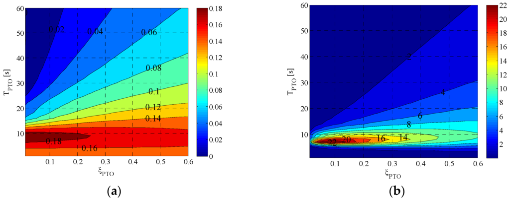
Figure 13.
(a) The heave motion reduction ratio under IRW-1 with different and ; (b) the capture width under IRW-6 with different and .
Figure 13.
(a) The heave motion reduction ratio under IRW-1 with different and ; (b) the capture width under IRW-6 with different and .
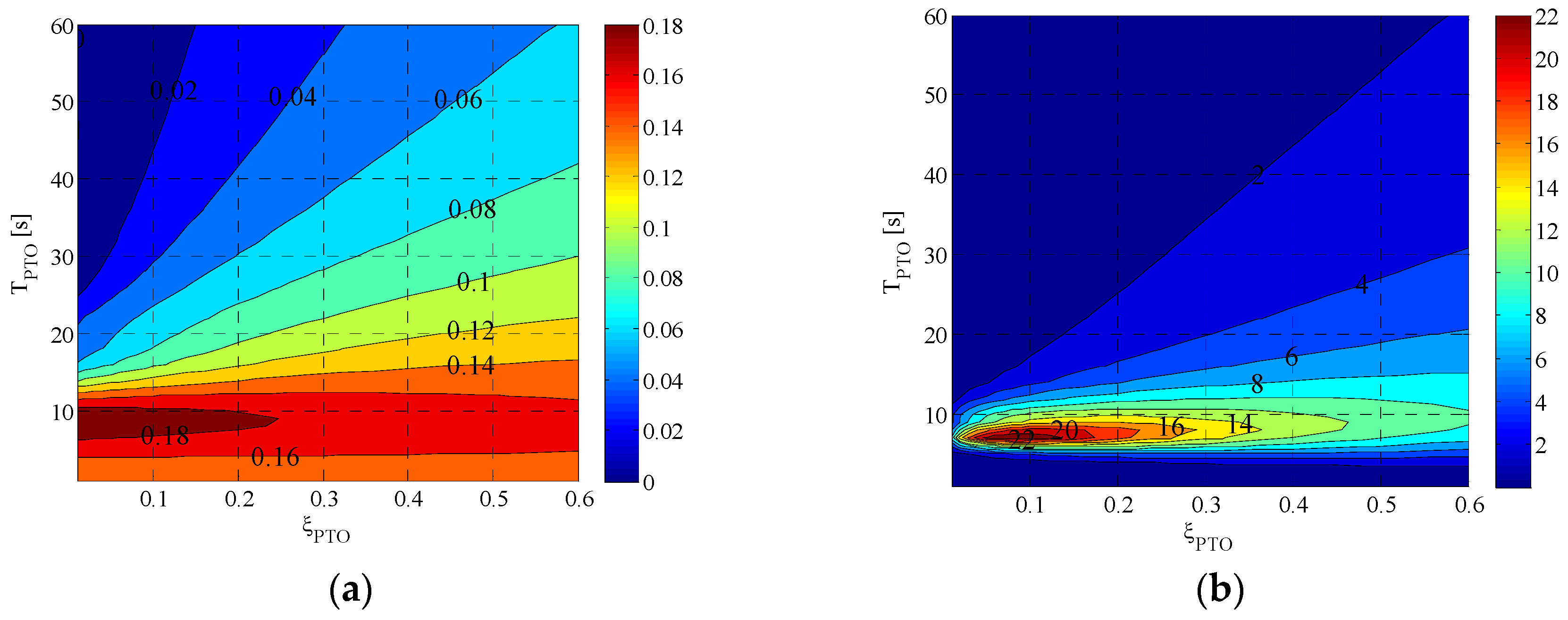
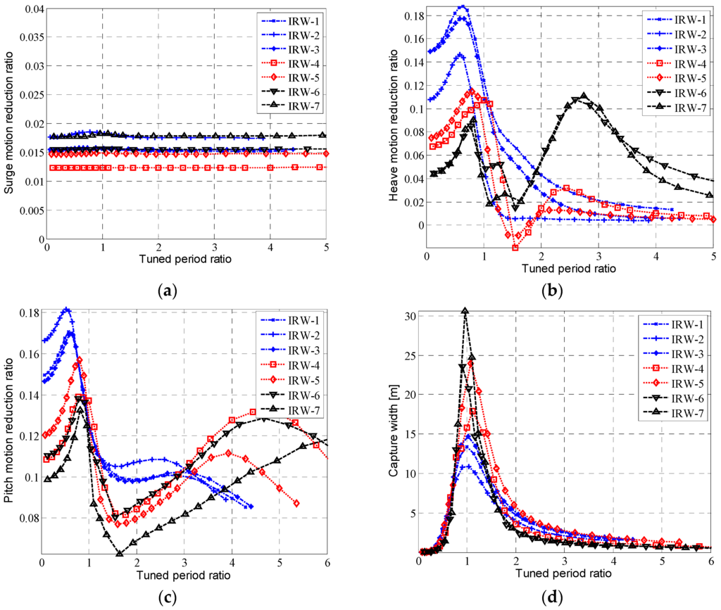
Figure 14.
(a) The surge motion reduction ratio with the tuned period ratio under different wave conditions with ; (b) the heave motion reduction ratio with the tuned period ratio under different wave conditions; (c) the pitch motion reduction ratio with the tuned period ratio under different wave conditions; (d) the capture width with the tuned period ratio under different wave conditions.
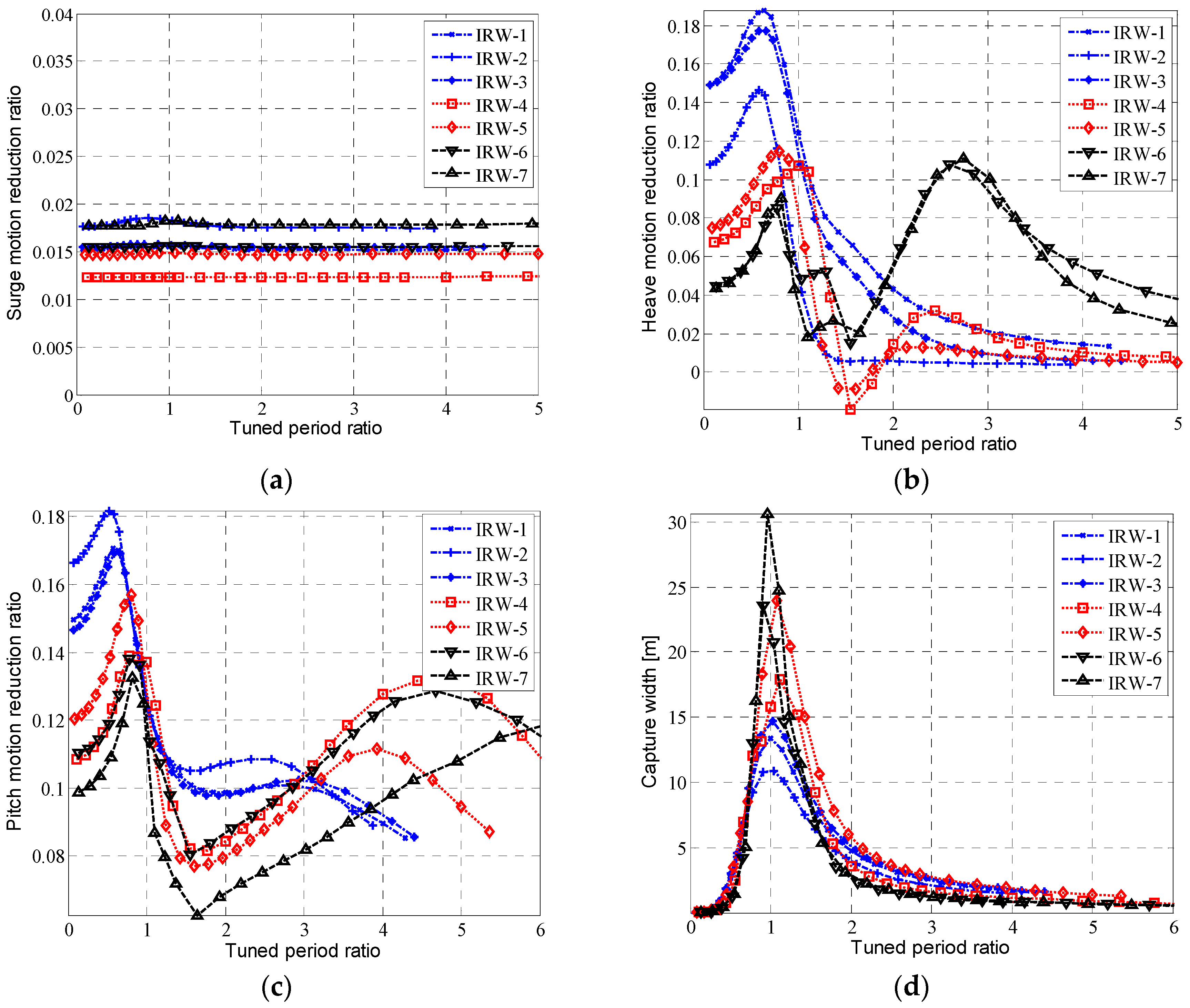
Figure 14a shows that the tuned period has a small effect on surge motion suppression, as the major contributor of the THPEH to the surge motion is the additional mass of the plates. For heave motion reduction and pitch motion reduction analysis, Figure 14b,c indicate that for sever wave conditions IRW-1~3, the optimal tuned period ratio is approximately 0.7, which is not far from 1. This result indicates that the THPEH system should be tuned near the wave peak period to achieve the maximum control effect under these harsh wave conditions. For smaller waves IRW-4~7, there are two peaks for the tuned period ratio; one is approximately 1, and another is approximately 2~3 for heave motion reduction and 4~7 for pitch motion reduction. This result indicates that the THPEH system can be tuned near the wave peak period or natural period to achieve the maximum control effect under these calm wave conditions. For energy absorption efficiency analysis, the capture width achieves its maximum value under different wave conditions while the tuned period ratio is approximately 1, which means the THPEH system is tuned to the wave peak period.
When safety is the prime consideration, the parameters should be chosen according to the maximum heave motion under severe wave conditions. In this paper, the tuned period of the THPEH is set to 9 s because of the maximum heave motion reduction under IRW-1.
5.3. Parameter Study of the Damping Coefficient of the Power Take-Off System (PTO)
Although the damping ratio of the PTO system has a small effect on the motion control of the platform, it is the key factor for energy absorption and relative motion between the heave plate and the platform. The relations between the motion reduction ratio, the relative motion between Plate 1 and the platform, the capture width and the PTO damping ratio are shown in Figure 15.
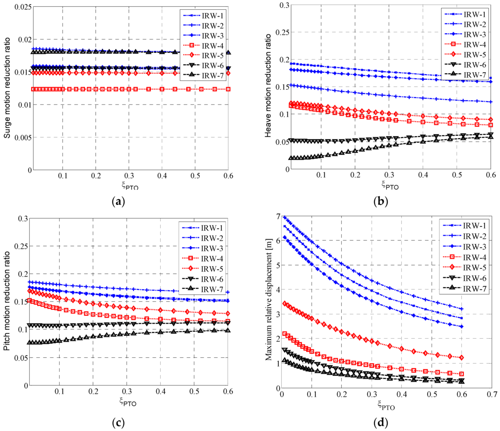
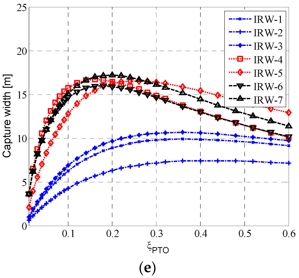
Figure 15.
(a) The surge motion reduction ratio with the PTO damping ratio under different wave conditions with ; (b) the surge motion reduction ratio with the PTO damping ratio under different wave conditions with ; (c) the pitch motion reduction ratio with the PTO damping ratio under different wave conditions with ; (d) the maximum relative displacement of Plate 1 with the PTO damping ratio under different wave conditions with ; (e) the capture width with the PTO damping ratio under different wave conditions with .


Figure 15a shows that the PTO damping ratio has a small effect on surge motion suppression. For heave motion reduction and pitch motion reduction analysis, Figure 15b,c indicate that for wave conditions IRW-1~5, the motion reduction ratios decrease with increasing damping. However, for the average wave condition IRW-6~7, the relations between the reduction ratio and damping are opposite. The maximum relative displacement between Plate 1 and the platform is shown in Figure 15d, which illustrates that the amplitude of the relative displacement decreases with increasing PTO damping ratio. As shown in Figure 15e, there is an optimal PTO damping ratio for each wave condition to achieve maximum energy absorption. Although the optimal value depends on the wave condition, the optimal PTO damping ratio can be chosen according to the curve of the capture width and damping ratio under IRW-6 and IRW-7. In this paper, the optimal PTO damping ratio is set to 0.2.
6. Results and Discussion
According to the parameter study of the THPEH system in the last section, the optimal parameters of the THPEH system are selected. The side length of the plate is 17 meters, the tuned period of the THPEH system is 9 s, and the damping ratio of the PTO system is 20%. Under these conditions, the connection parameters are
The performance of the THPEH on the semi-submersible platform under different wave conditions is analyzed. The results include the heave motion response, the pitch response and capture power, shown in Table 5. The THPEH system could reduce up to 20% of the heave motion and 10% of the pitch motion under severe wave conditions and provide up to 40 kW power under average wave conditions. Moreover, the system could theoretically capture more than 1000 kW of power under 100-year wave conditions in the South China Sea.
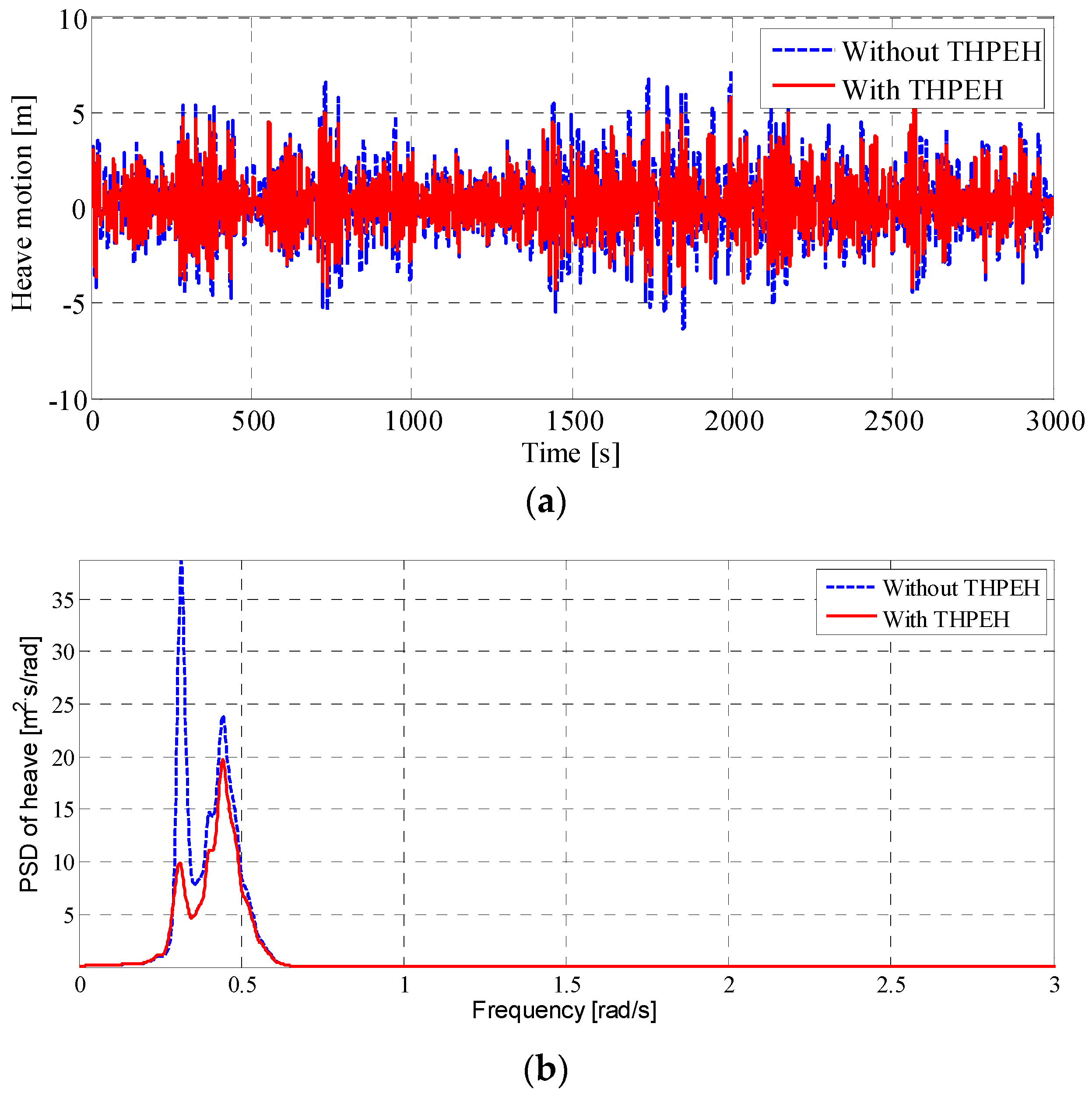
Figure 16 and Figure 17 illustrate the time histories and power spectra of the heave motion and pitch motion under IRW-1. They show that the THPEH could reduce the amplitude for both the heave motion and the pitch motion. For the heave and pitch motions, the wave frequency motion and low natural frequency motion are suppressed, although the THPEH system is tuned to the wave frequency. The reduction effect of the low natural frequency motion is more significant compared to the wave frequency motion.
Table 5.
Performances of the THPEH system working on the semi-submersible platform under different wave conditions.
| Wave Name | Heave Motion Response | Pitch Motion Response | Energy Harvesting | |||||
|---|---|---|---|---|---|---|---|---|
| without THPEH (m) | with THPEH (m) | Reduction Ratio | without THPEH (Degree) | with THPEH (Degree) | Reduction Ratio | (kW) | (m) | |
| IRW-1 | 1.99 | 1.62 | 18.25% | 4.34 | 3.86 | 11.03% | 1040.5 | 1.02 |
| IRW-2 | 2.31 | 1.98 | 13.96% | 4.85 | 4.30 | 11.43% | 972.11 | 0.72 |
| IRW-3 | 1.72 | 1.42 | 17.24% | 3.86 | 3.44 | 10.96% | 910.27 | 1.11 |
| IRW-4 | 0.16 | 0.14 | 9.73% | 0.75 | 0.70 | 7.20% | 130.64 | 1.89 |
| IRW-5 | 0.57 | 0.51 | 10.74% | 1.67 | 1.51 | 9.42% | 367.95 | 1.86 |
| IRW-6 | 0.05 | 0.05 | 5.26% | 0.29 | 0.28 | 4.64% | 39.63 | 1.82 |
| IRW-7 | 0.04 | 0.04 | 3.30% | 0.20 | 0.19 | 2.94% | 24.88 | 1.97 |
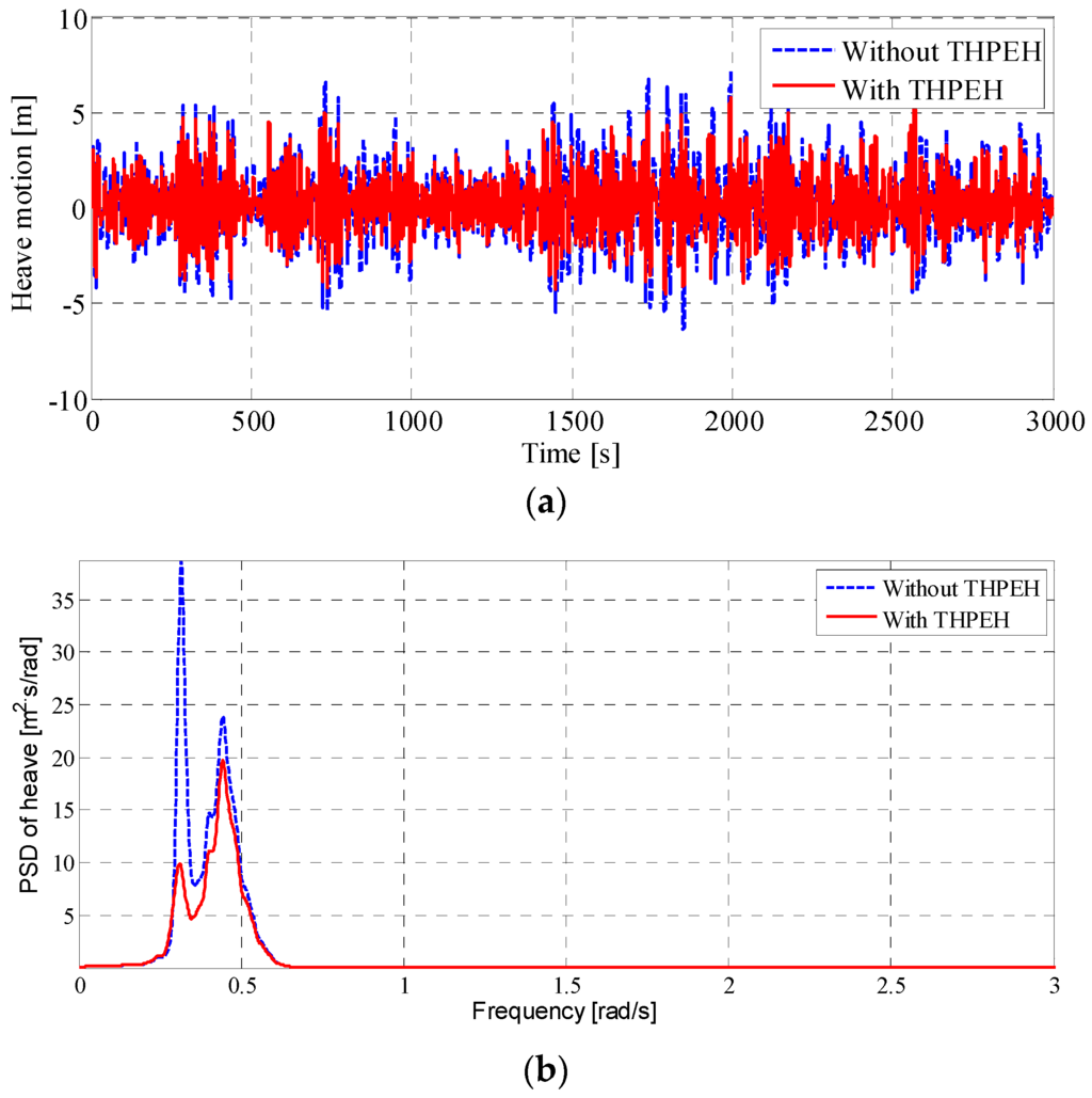
Figure 16.
(a) The time histories of the heave motion with and without the THPEH system under IRW-1; (b) the power spectra of the heave motion with and without the THPEH system under IRW-1.
Figure 16.
(a) The time histories of the heave motion with and without the THPEH system under IRW-1; (b) the power spectra of the heave motion with and without the THPEH system under IRW-1.
The traces of the control force against the displacement and velocity in the heave and pitch motions are shown in Figure 18 and Figure 19. This result indicates that the control forces in the heave and pitch motions both have a damping force characteristic and a slight negative stiffness characteristic. The damping force characteristic is the reason why the motion reduction effect on the low natural frequency motion is more significant and is due to the power spectrum figures. The negative stiffness forces make the natural period farther away from the peak period of the waves.
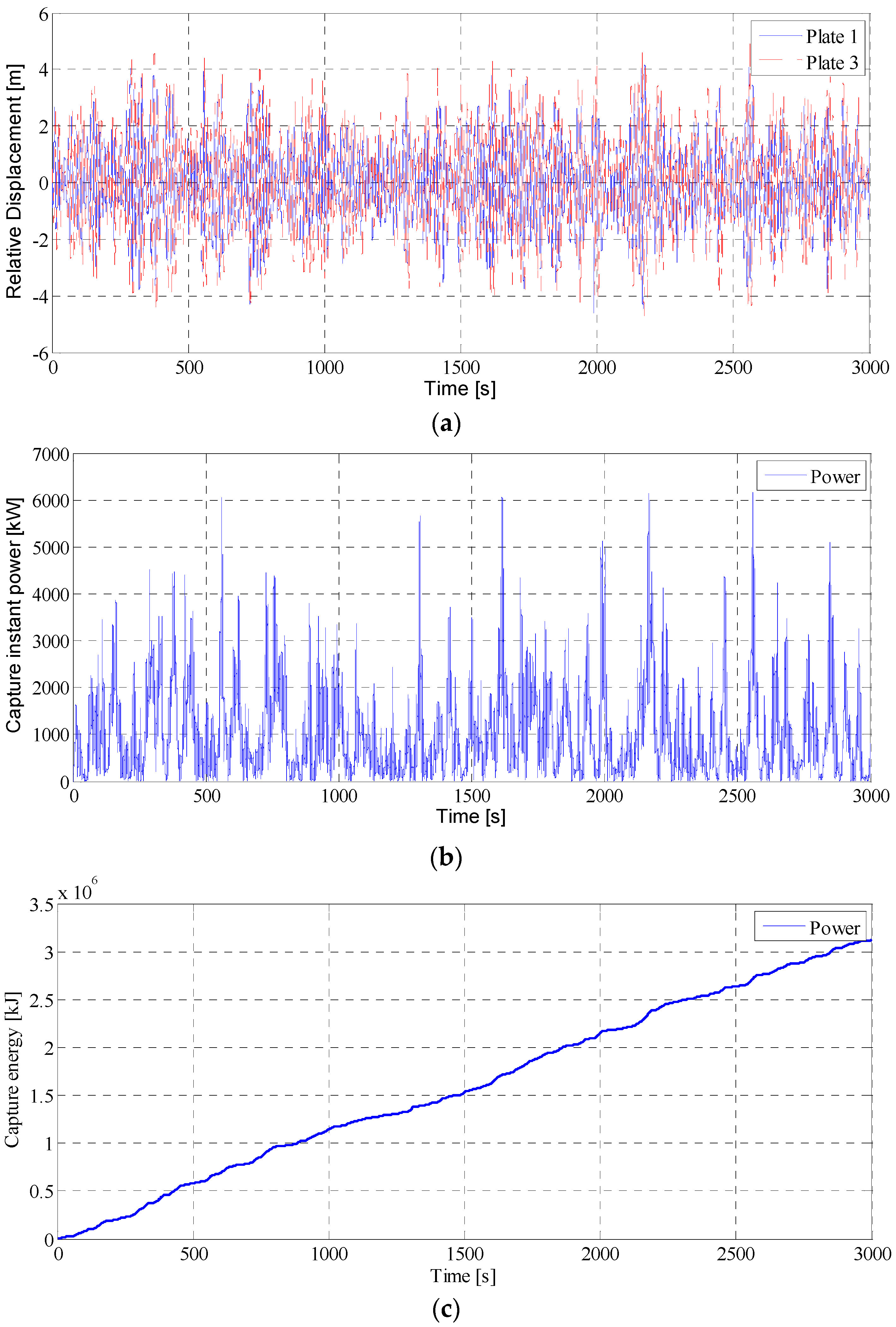
Figure 20 shows the time histories of the relative motions of the plates, the instant power and the capture energy of the THPEH system under IRW-1. This result indicates that the THPEH system could harvest considerable power while suppressing the motion of the platform.

Figure 17.
(a) The time histories of the pitch motion with and without the THPEH system under IRW-1; (b) the power spectra of the pitch motion with and without the THPEH system under IRW-1.
Figure 17.
(a) The time histories of the pitch motion with and without the THPEH system under IRW-1; (b) the power spectra of the pitch motion with and without the THPEH system under IRW-1.
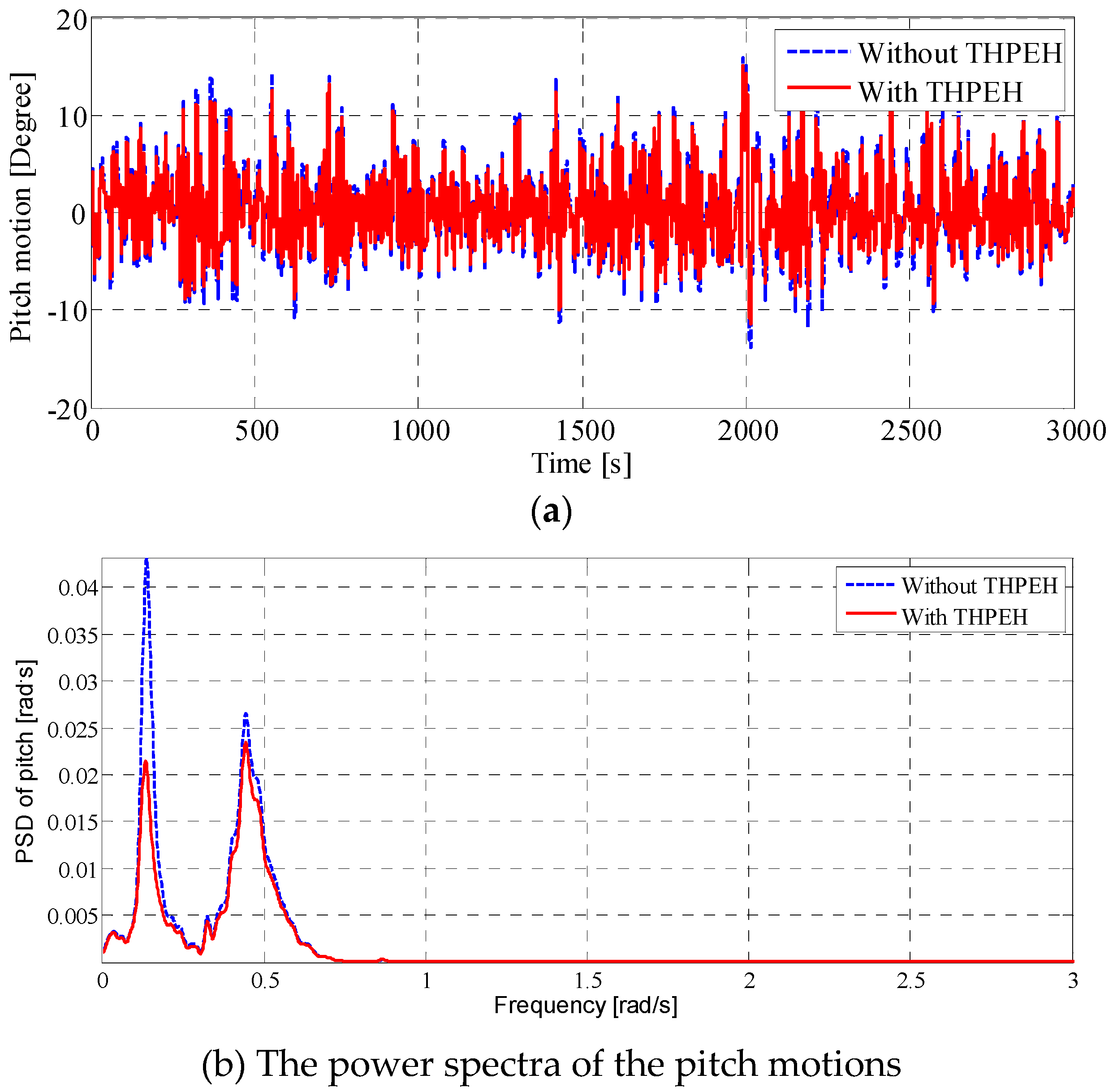

Figure 18.
(a) The relation between the control force in the heave motion from the THPEH system and the heave displacement of the platform; (b) the relation between the control force in the heave motion from the THPEH system and the heave velocity of the platform.
Figure 18.
(a) The relation between the control force in the heave motion from the THPEH system and the heave displacement of the platform; (b) the relation between the control force in the heave motion from the THPEH system and the heave velocity of the platform.
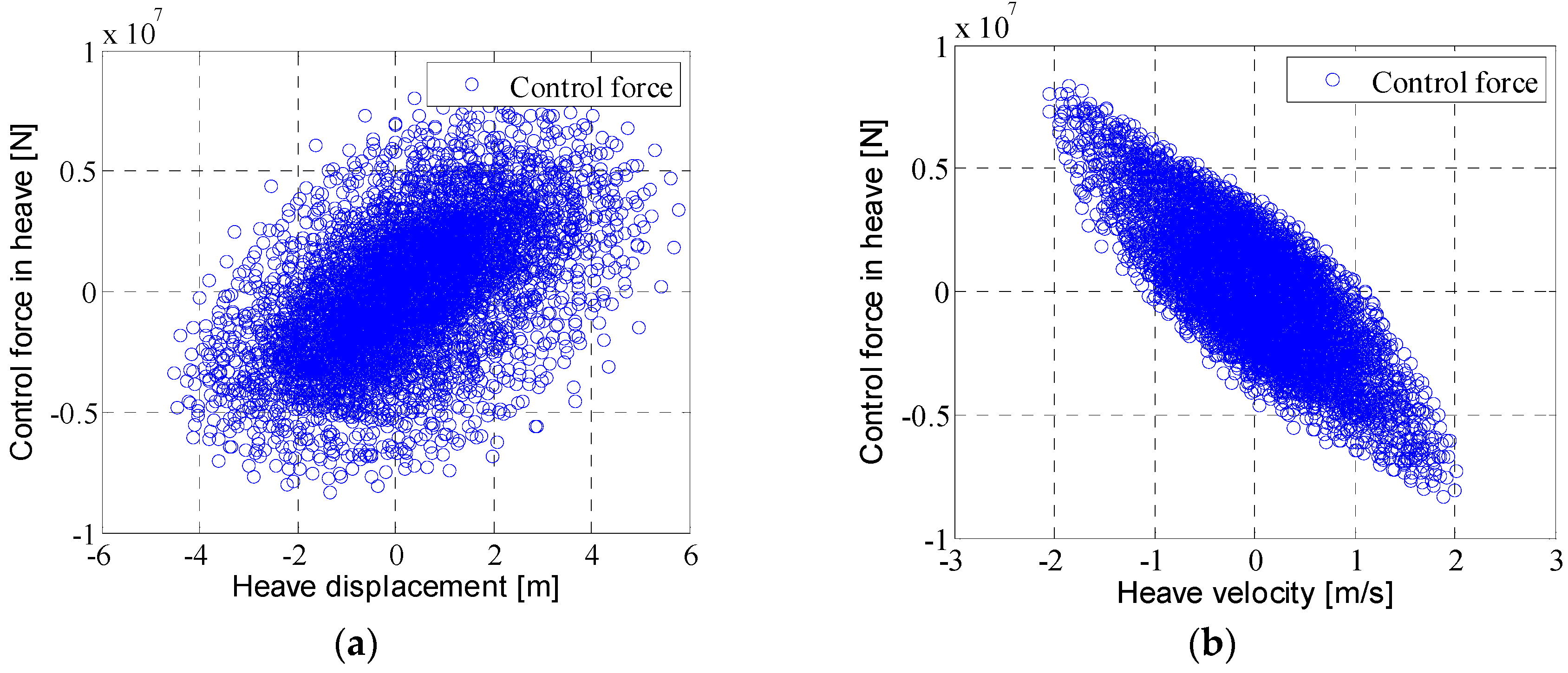
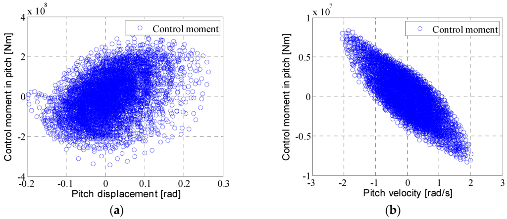
Figure 19.
(a) The relation between the control force in the pitch motion from the THPEH system and the pitch displacement of the platform; (b) the relation between the control force in the pitch motion from the THPEH system and the pitch velocity of the platform.
Figure 19.
(a) The relation between the control force in the pitch motion from the THPEH system and the pitch displacement of the platform; (b) the relation between the control force in the pitch motion from the THPEH system and the pitch velocity of the platform.

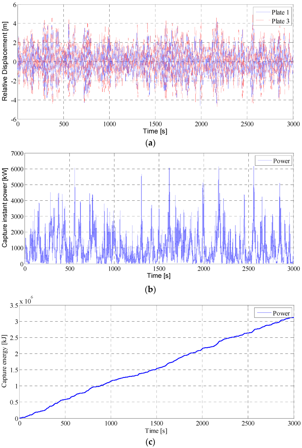
Figure 20.
(a) The relative displacement of Plate1 and Plate3 under IRW-1; (b) the captured instant power of the THPEH system under IRW-1; (c) the captured energy of the THPEH system under IRW-1.
Figure 20.
(a) The relative displacement of Plate1 and Plate3 under IRW-1; (b) the captured instant power of the THPEH system under IRW-1; (c) the captured energy of the THPEH system under IRW-1.
7. Conclusions
This paper presents a tuned heave plate system (THPEH) used on a semi-submersible platform for suppressing the platform’s motions and harvesting energy from the wave-induced response. Based on the numerical model of the platform, which is modified and testified by a 1:70 scale model test, parameters including the size, the tuned period and the damping ratio of the THPEH system are studied systematically. The effects of the THPEH system on motion suppression and energy harvesting under different wave conditions are investigated. The results show the following:
- By introducing a viscous damping matrix to the numerical model, the precision of the numerical model is acceptable compared to the wave tank tests.
- For the reasonable plate size range, the control performance of the platform motion increases with the growth of the plate size. However, there is an optimal size of the plate under each wave condition for energy harvesting.
- The novel THPEH system could significantly reduce the motions of the semi-submersible platform. The optimal tuned natural period of the THPEH depends on the wave condition. For normal severe wave conditions in the South China Sea, the optimal tuned period is approximately 9 s.
- For different wave conditions, in order to achieve the maximum energy absorption, the damping ratio of the THPEH system is approximately 20%. The damping ratio has significant impacts on the relative motion range. Moreover, the optimal tuned natural period for energy harvesting is near the wave peak frequency.
- With optimal parameters, the control forces in the heave and pitch motions have both a damping force characteristic and a slight negative stiffness characteristic, which are all positive for motion suppression.
- The novel tuned heave plate energy harvesting system could reduce the motion of a semi-submersible platform and generate considerable power, which makes the THPEH system have broad application prospects.
Acknowledgments
The research was financially supported by the National Natural Science Foundation of China (the Grant No.: 50921001) and the National Major Fundamental Research Program (973 Plan, the Grant No.: 2011CB013705).
Author Contributions
Kun Liu carried out most of the work presented here, Jinping Ou was the supervisors of this work, and Haizhi Liang had a relevant contribution with the wave tank experiment and the numerical simulations.
Conflicts of Interest
The authors declare no conflict of interest.
References
- Polinder, H.; Damen, M.E.; Gardner, F. Linear PM generator system for wave energy conversion in the AWS. IEEE Trans. Energy Convers. 2004, 19, 583–589. [Google Scholar] [CrossRef]
- Brekken, T.K.; von Jouanne, A.; Han, H.Y. Ocean wave energy overview and research at Oregon State University. In Proceedings of the 2009 IEEE Power Electronics and Machines in Wind Applications, Lincoln, NE, USA, 24–26 June 2009.
- Yeung, R.W.; Peiffer, A.; Tom, N.; Matlak, T. Design, analysis, and evaluation of the UC-Berkeley wave-energy extractor. J. Offshore Mech. Arct. Eng. 2012, 134, 021902. [Google Scholar] [CrossRef]
- Mavrakos, S.A. Hydrodynamic coefficients in heave of two concentric surface-piercing truncated circular cylinders. Appl. Ocean Res. 2004, 26, 84–97. [Google Scholar] [CrossRef]
- Falcão, A.F.O.; Cândido, J.; Justino, P.; Henriques, J. Hydrodynamics of the IPS buoy wave energy converter including the effect of non-uniform acceleration tube cross section. Renew. Energy 2012, 41, 105–114. [Google Scholar] [CrossRef]
- Cermelli, C.; Roddier, D.; Busso, C. MINIFLOAT: A novel concept of minimal floating platform for marginal field development. In Proceedings of the Fourteenth International Offshore and Polar Engineering Conference, Toulon, France, 23–28 May 2004.
- Murray, J.J.; Yang, C.; Cheng, C.; Nah, E. Two dry tree semisubmersible designs for ultra deep water post-Katrina Gulf of Mexico. In Proceedings of the ASME 2008 27th International Conference on Offshore Mechanics and Arctic Engineering, Estoril, Portugal, 15–20 June 2008.
- Chakrabarti, S.; Barnett, J.; Kanchi, H.; Mehta, A.; Yim, J. Design analysis of a truss pontoon semi-submersible concept in deep water. Ocean Eng. 2007, 34, 621–629. [Google Scholar] [CrossRef]
- Mills, T.; Chen, C.Y. Deep Draft Semi-Submersible Offshore Floating Structure. U.S. Patent 20070224000 A1, 27 September 2007. [Google Scholar]
- Frahm, H. Device for Damping Vibrations of Bodies. U.S. Patent 989958 A, 18 April 1911. [Google Scholar]
- Soong, T.T.; Dargush, G.F. Passive Energy Dissipation Systems in Structural Engineering; Wiley: Hoboken, NJ, USA, 1997. [Google Scholar]
- Spencer, B., Jr.; Nagarajaiah, S. State of the art of structural control. J. Struct. Eng. 2003, 129, 845–856. [Google Scholar] [CrossRef]
- Housner, G.W.; Bergman, L.; Caughey, T.; Chassiakos, A.; Claus, R.; Masri, S.; Skelton, R.; Soong, T.; Spencer, B.; Yao, J.; et al. Structural control: Past, present, and future. J. Eng. Mech. 1997, 123, 897–971. [Google Scholar] [CrossRef]
- Xu, H.; Zhang, C.; Li, H.; Ou, J. Real-time hybrid simulation approach for performance validation of structural active control systems: A linear motor actuator based active mass driver case study. Struct. Control Health Monit. 2014, 21, 574–589. [Google Scholar] [CrossRef]
- Kourakis, I. Structural Systems and Tuned Mass Dampers of Super-Tall Buildings: Case Study of Taipei 101; Massachusetts Institute of Technology: Cambridge, MA, USA, 2007. [Google Scholar]
- Xu, H.B.; Zhang, C.; Li, H.; Tan, P.; Ou, J.; Zhou, F. Active mass driver control system for suppressing wind-induced vibration of the Canton Tower. Smart Struct. Syst. 2014, 13, 281–303. [Google Scholar] [CrossRef]
- Zhu, S.; Shen, W.A.; Xu, Y.L. Linear electromagnetic devices for vibration damping and energy harvesting: Modeling and testing. Eng. Struct. 2012, 34, 198–212. [Google Scholar] [CrossRef]
- Ali, S.F.; Adhikari, S. Energy harvesting dynamic vibration absorbers. J. Appl. Mech. 2013, 80, 041004. [Google Scholar] [CrossRef]
- Tang, X.; Zuo, L. Simulation and experiment validation of simultaneous vibration control and energy harvesting from buildings using tuned mass dampers. In Proceedings of the 2011 American Control Conference (ACC), San Francisco, CA, USA, 29 June–1 July 2011.
- Liu, K.; Zhu, H.; Ou, J. Application of TMD in heave response control of semi-submersible platforms. Eng. Mech. 2011, 28, 205–210. [Google Scholar]
- Zhu, H.; Ou, J.; Zhai, G. Conceptual design of a deep draft semi-submersible platform with a moveable heave-plate. J. Ocean Univ. China 2012, 11, 7–12. [Google Scholar] [CrossRef]
- Cummins, W. The impulse response function and ship motions. Schiffstechnik 1962, 47, 101–109. [Google Scholar]
- Hals, J.; Falnes, J.; Moan, T. Constrained optimal control of a heaving buoy wave-energy converter. J. Offshore Mech. Arct. Eng. 2011, 133, 011401. [Google Scholar] [CrossRef]
- Tao, L.; Cai, S. Heave motion suppression of a Spar with a heave plate. Ocean Eng. 2004, 31, 669–692. [Google Scholar] [CrossRef]
- Tao, L.; Dray, D. Hydrodynamic performance of solid and porous heave plates. Ocean Eng. 2008, 35, 1006–1014. [Google Scholar] [CrossRef]
- Zhang, F.; Yang, J.; Li, R.; Hu, Z. Effects of heave plate on the hydrodynamic behaviors of cell spar platform. In Proceedings of the 25th International Conference on Offshore Mechanics and Arctic Engineering, Hamburg, Germany, 4–9 June 2006.
- Prislin, I.; Blevins, R.; Halkyard, J. Viscous damping and added mass of solid square plates. In Proceedings of the 17th International Conference on Offshore Mechanics and Arctic Engineering, Lisbon, Portugal, 15–19 June 1998.
© 2016 by the authors; licensee MDPI, Basel, Switzerland. This article is an open access article distributed under the terms and conditions of the Creative Commons by Attribution (CC-BY) license (http://creativecommons.org/licenses/by/4.0/).