
Experimental and Potential Analysis of a Single-Valve Expander for Waste Heat Recovery of a Gasoline Engine

Abstract
:1. Introduction
2. Experimental System for Waste Heat Recovery
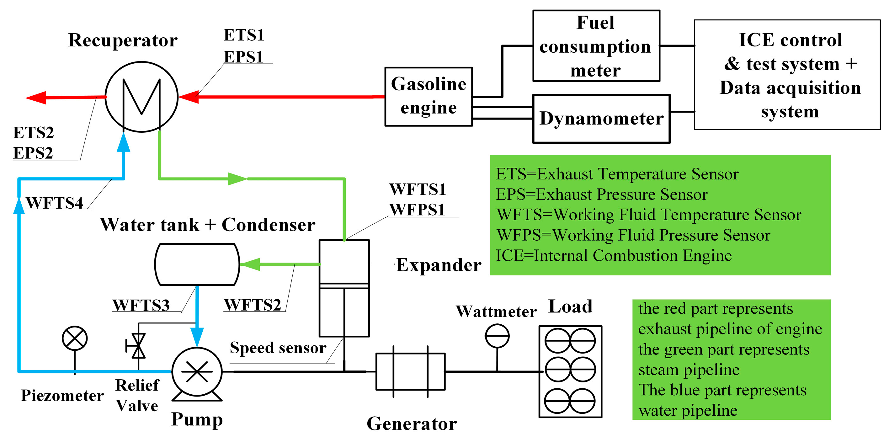
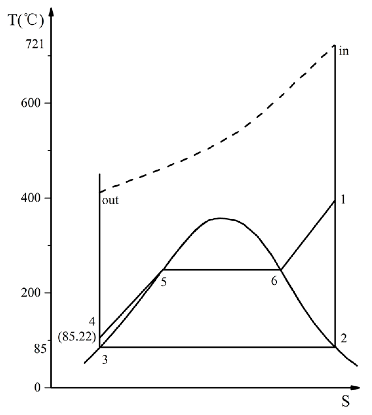
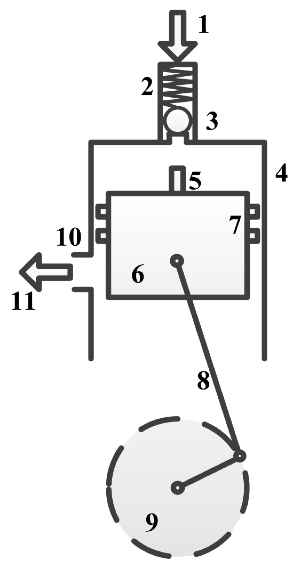
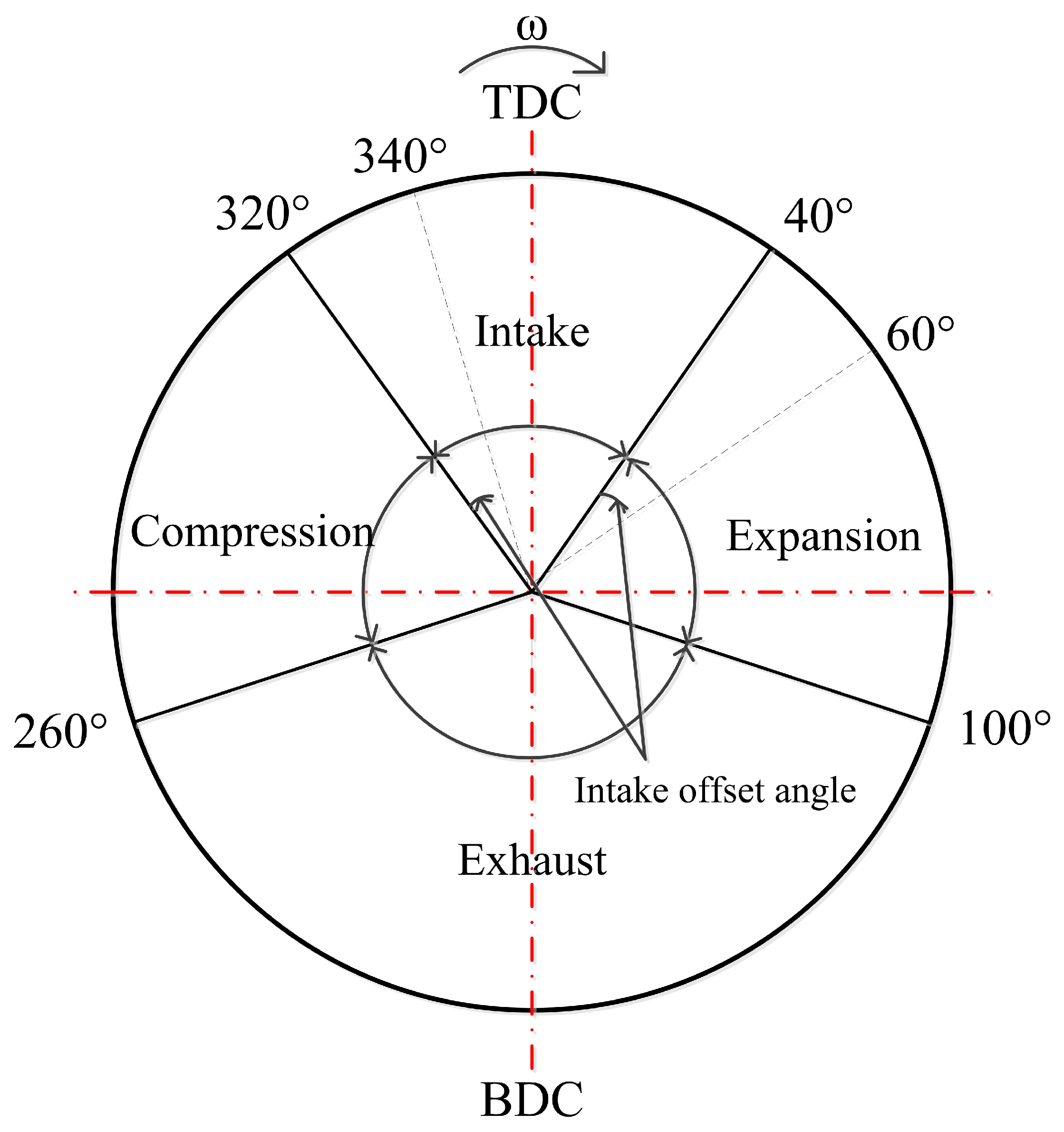
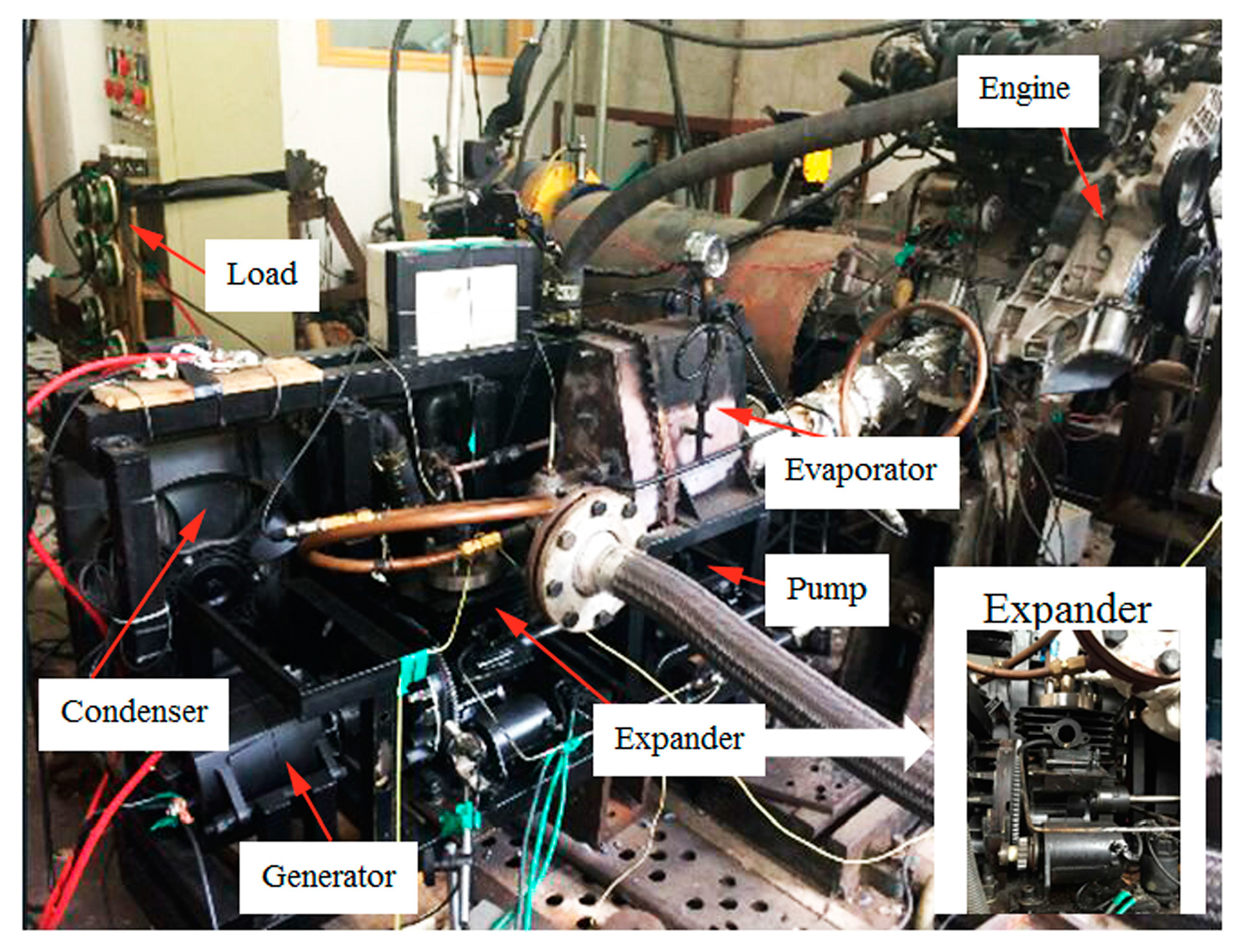
2.1. Experimental Principle and Bench Description
2.2. Test and Data Acquisition System
3. Experimental Results and Analysis
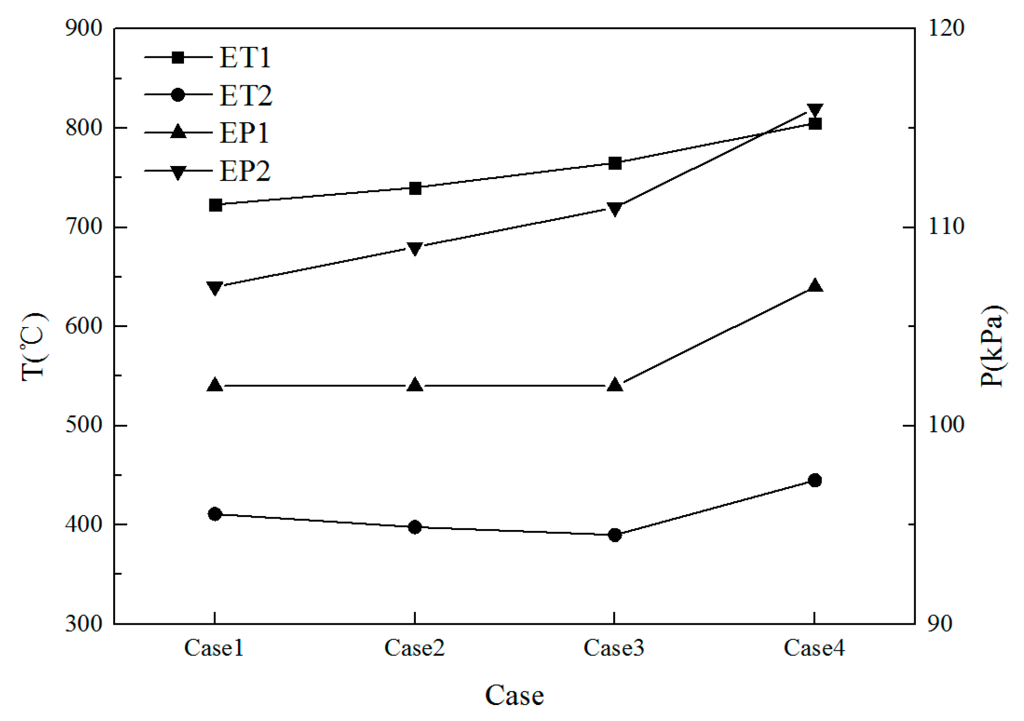
3.1. Recuperator Influence on the Gasoline Engine
3.2. Performance of Expander and Recovery System
3.3. Performance Analysis of Waste Heat Recovery System
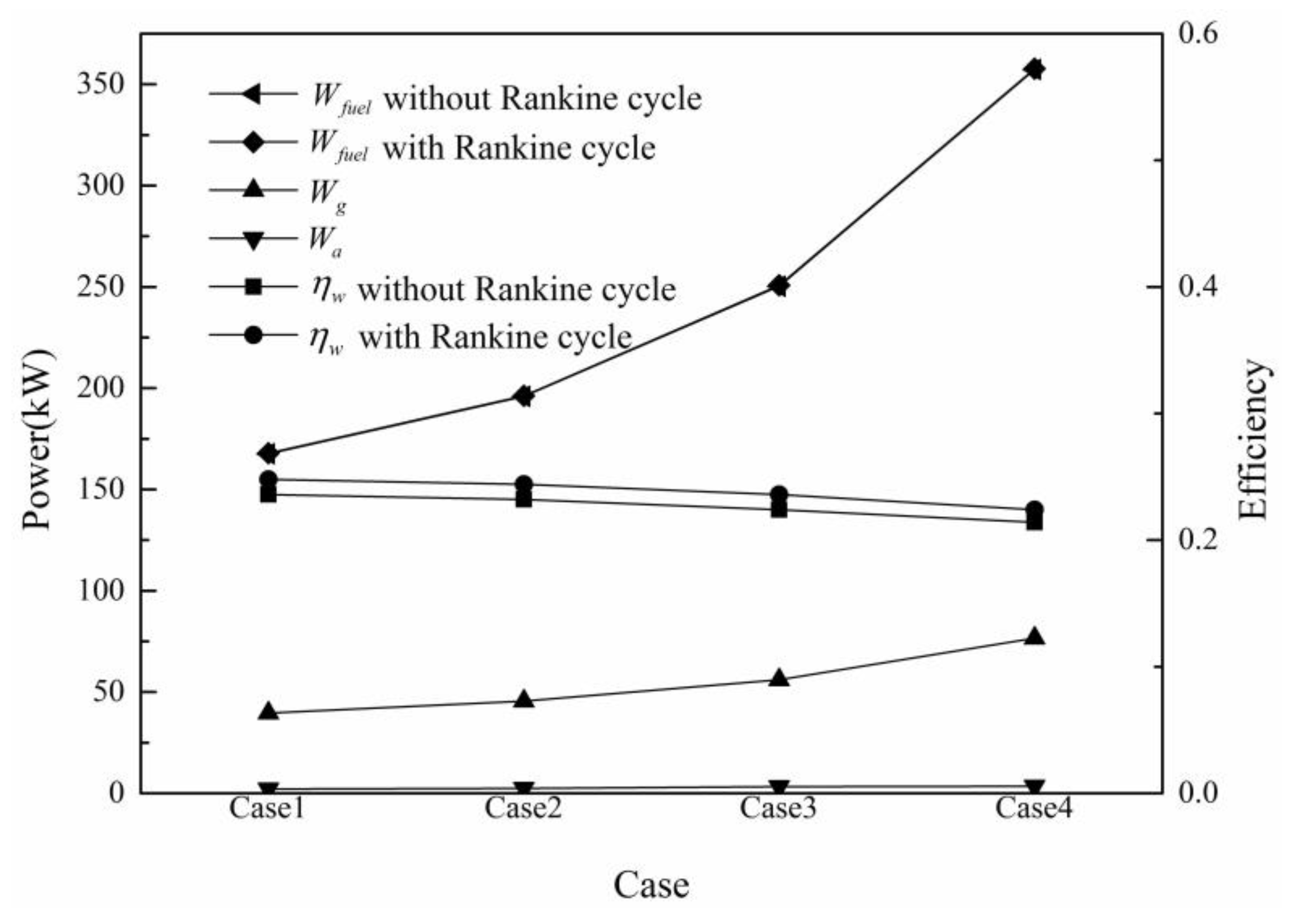
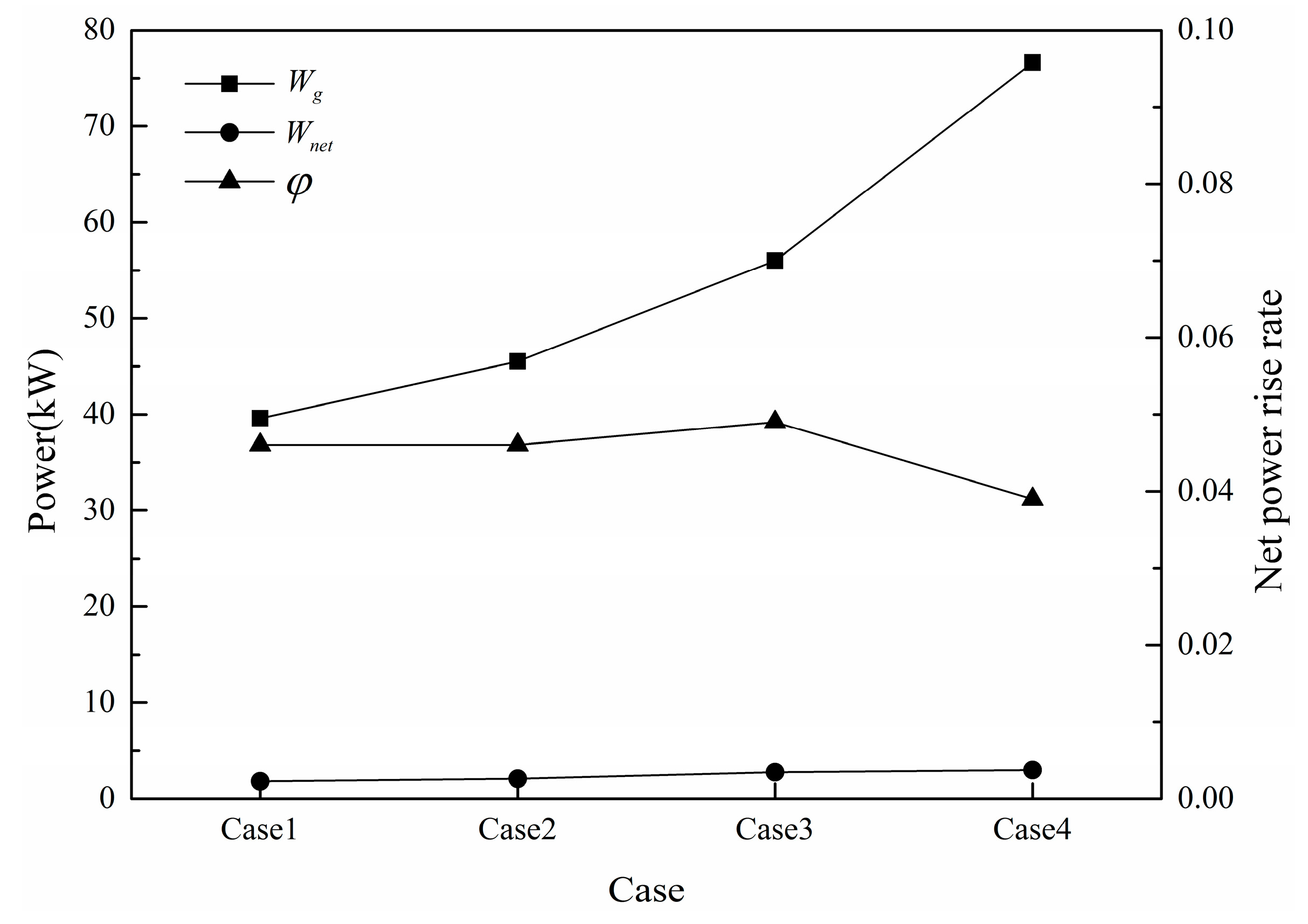
3.3.1. Net Power Rise Rate
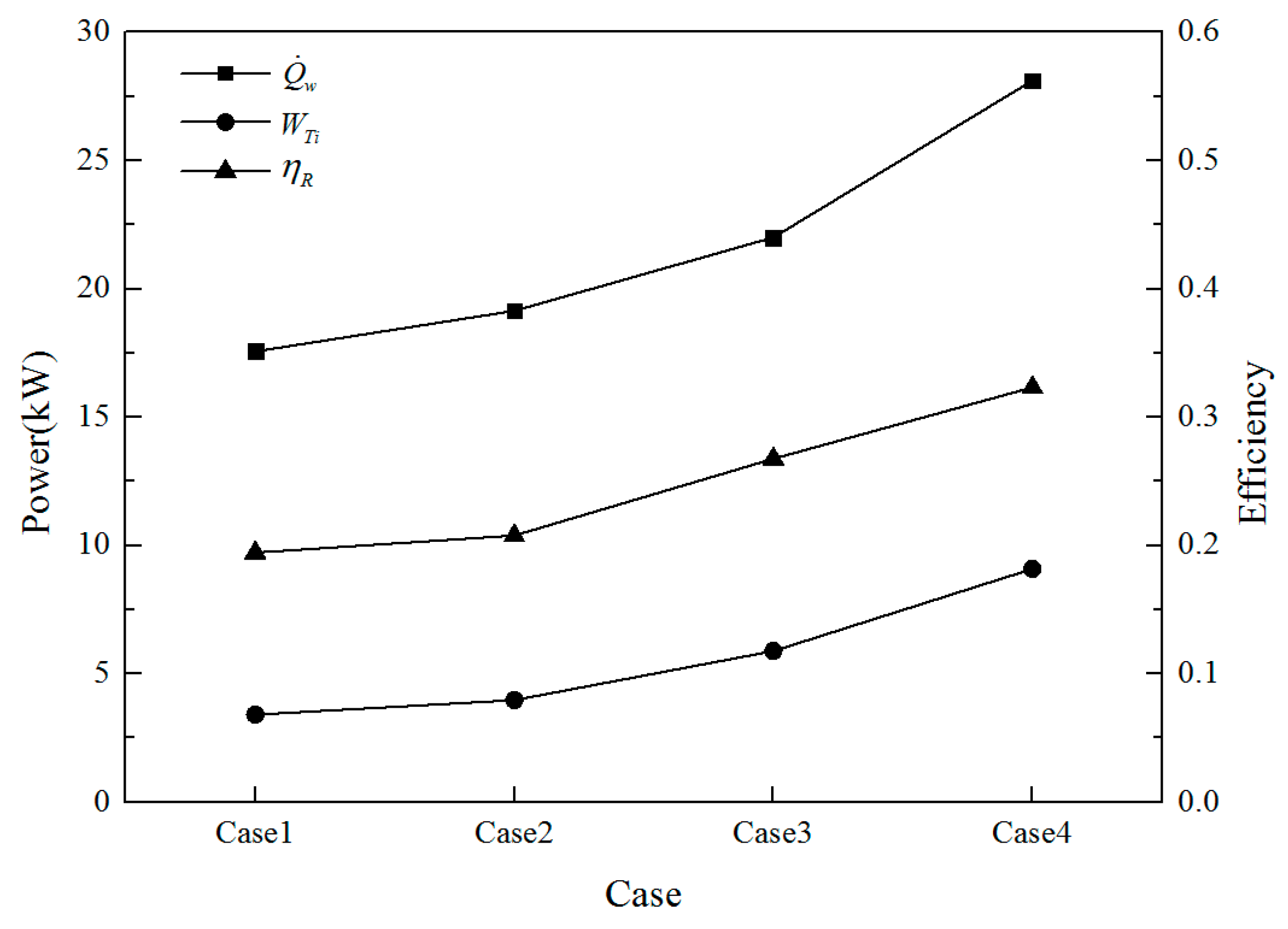
3.3.2. Thermal Efficiency of Rankine Cycle
3.3.3. Overall Combined Cycle System Efficiency
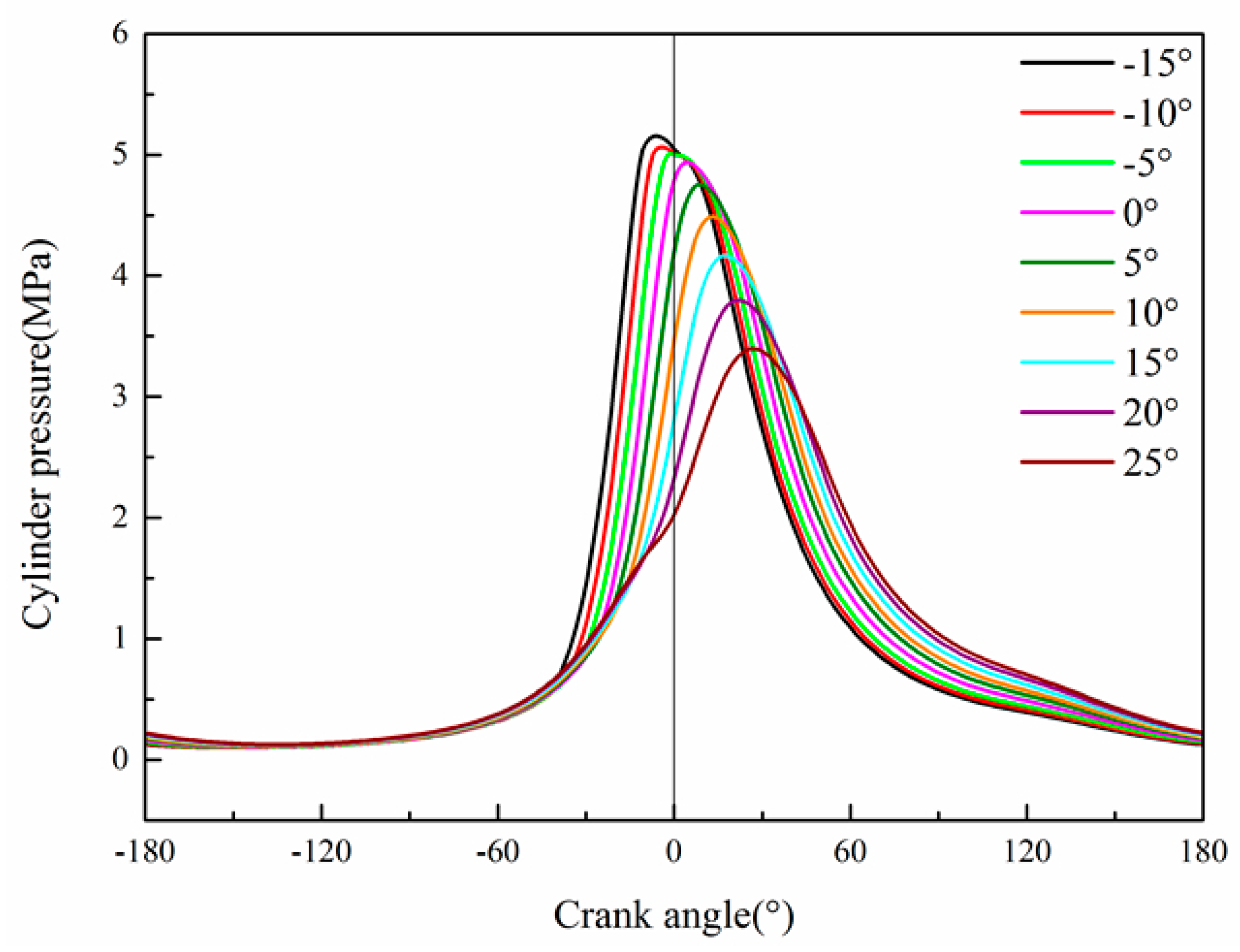
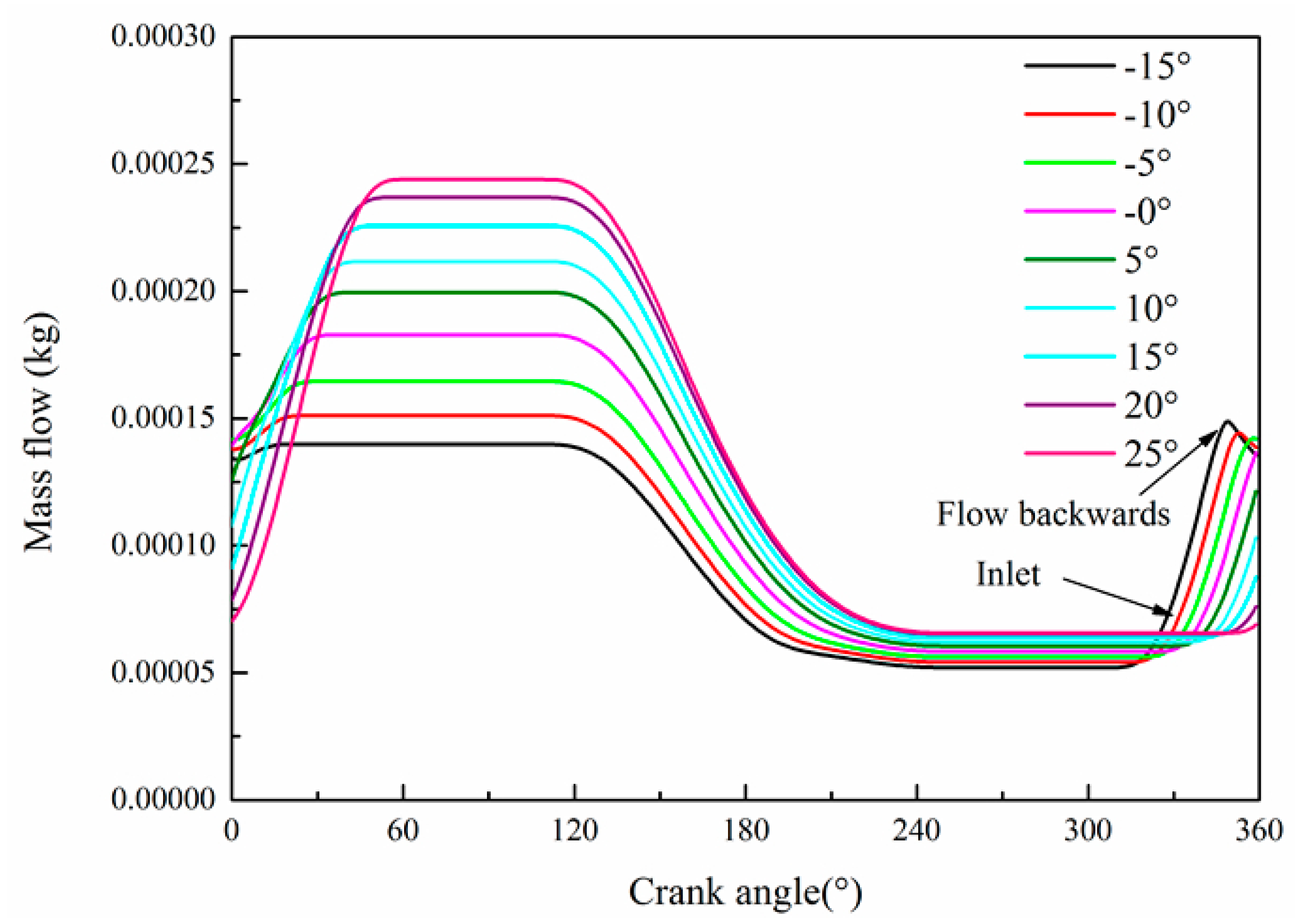
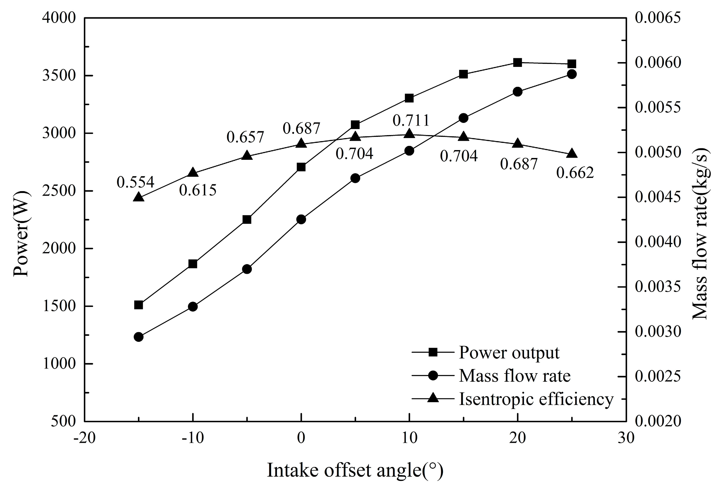
4. Analysis of Potential Power Increase of the Expander
5. Conclusions
Acknowledgments
Author Contributions
Conflicts of Interest
Abbreviation
| ICE | Internal combustion engine |
| NA | Naturally aspirated |
| P | Pressure, Pa |
| V | Volume of the steam in the cylinder, m3 |
| T | Temperature, °C |
| ET | Exhaust temperature, °C |
| EP | Exhaust pressure, Pa |
| WFT | Working fluid temperature, °C |
| WFP | Working fluid pressure, Pa |
| Net power rise rate | |
| Wnet | Net power output of recovery system, W |
| We | Expander power output, W |
| Wp | Pump power consumption, W |
| Wloss | Gasoline engine power losses, W |
| Wa | Shaft power of expander, W |
| Wg | Gasoline engine power output, W |
| Thermal efficiency of Rankine cycle system | |
| WTi | Ideal indicated power, W |
| Energy absorbed by the working fluid in unit time, W | |
| Theoretical mass flow rate of working fluid, kg | |
| Mass flow rate of the working fluid, kg | |
| Specific enthalpy of the working fluid, kJ/kg | |
| Wi | Indicated power, W |
| Overall combined cycle system efficiency | |
| Wfuel | Fuel heat, W |
| NIST | National Institute of Standards and Technology |
| TDC | Top dead centre |
| BDC | Bottom dead centre |
| Wi | Indicated power, W |
| isentropic efficiency of expander |
References
- Katsanos, C.O.; Hountalas, D.T.; Pariotis, E.G. Thermodynamics analysis of a Rankine cycle applied on a diesel truck engine using steam and organic medium. Energy Convers. Manag. 2012, 60, 68–76. [Google Scholar] [CrossRef]
- Wang, T.; Zhang, Y.; Peng, Z.; Shu, G. A review of researches on thermal exhaust heat recovery with Rankine cycle. Renew. Sustain. Energy Rev. 2011, 15, 2862–2871. [Google Scholar] [CrossRef]
- Domingues, A.; Santos, H.; Costa, M. Analysis of vehicle exhaust waste heat recovery potenti al using a Rankine cycle. Energy 2013, 49, 71–85. [Google Scholar] [CrossRef]
- Bari, S.; Hossain, S.N. Waste heat recovery from a diesel engine using shell and tube heat exchanger. Appl. Therm. Eng. 2013, 61, 355–363. [Google Scholar] [CrossRef]
- Yang, K.; Zhang, H.; Song, S.; Zhang, J.; Wu, Y.; Zhang, Y.; Wang, H.; Chang, Y.; Bei, C. Performance Analysis of the Vehicle Diesel Engine-ORC Combined System Based on a Screw Expander. Energies 2014, 7, 3400–3419. [Google Scholar] [CrossRef]
- He, M.; Zhang, X.; Zeng, K.; Gao, K. A combined thermodynamic cycle used for waste heat recovery of internal combustion engine. Energy 2011, 36, 6821–6829. [Google Scholar] [CrossRef]
- Galindo, J.; Dolz, V.; Royo-Pascual, L.; Haller, R.; Melis, J. Modeling and Experimental Validation of a Volumetric Expander Suitable for Waste Heat Recovery from an Automotive Internal Combustion Engine Using an Organic Rankine Cycle with Ethanol. Energies 2016, 9, 1–18. [Google Scholar] [CrossRef]
- Yun, K.T.; Cho, H.; Luck, R.; Mago, P.J. Modeling of reciprocating internal combustion engines for power generation and heat recovery. Appl. Energy 2013, 102, 327–335. [Google Scholar] [CrossRef]
- Dolz, V.; Vovella, R.; Garcia, A.; Sanchez, J. HD diesel engine equipped with a bottoming Rankine cycle as a waste heat recovery system. Part 1: Study and analysis of the waste heat energy. Appl. Therm. Eng. 2012, 36, 269–278. [Google Scholar] [CrossRef]
- Serrano, J.P.; Dolz, V.; Vovella, R.; Garcia, A. HD diesel engine equipped with a bottoming Rankine cycle as a waste heat recovery system. Part 2: Evaluation of alternative solutions. Appl. Therm. Eng. 2012, 36, 279–287. [Google Scholar] [CrossRef]
- Song, J.; Gu, C.W. Parametric analysis of a dual loop Organic Rankine Cycle (ORC) system for engine waste heat recovery. Energy Convers. Manag. 2015, 105, 995–1005. [Google Scholar] [CrossRef]
- Chowdhury, J.I.; Bao, K.N.; Thornhill, D. Modelling of Evaporator in Waste Heat Recovery System using Finite Volume Method and Fuzzy Technique. Energies 2015, 8, 14078–14097. [Google Scholar] [CrossRef]
- Morgan, D.; Patel, P.; Doyle, E.; Raymond, R.; Sakhuja, R.; Barber, K. Laboratory Test Results Low Emission Rankine-Cycle Engine with Organic-Based Working Fluid and Reciprocating Expander for Automobiles. In Proceedings of the 8th Intersociety Energy Conversion Engineering Conference, Philadelphia, PA, USA, 13–17 August 1973.
- Iii, C.S.; Depcik, C. Review of organic Rankine cycles for internal combustion engine exhaust waste heat recovery. Appl. Therm. Eng. 2013, 51, 711–722. [Google Scholar]
- Wei, M.S.; Fang, J.L.; Ma, C.C.; Danish Syed, N. Waste heat recovery from heavy-duty dieselengine exhaust gases by medium temperature ORC system. Sci. China Technol. Sci. 2011, 54, 2746–2753. [Google Scholar] [CrossRef]
- Xie, H.; Yang, C. Dynamic behavior of Rankine cycle system for waste heat recovery of heavy duty diesel engines under driving cycle. Appl. Energy 2013, 112, 130–141. [Google Scholar] [CrossRef]
- Wang, J.F.; Yan, Z.Q.; Zhao, P.; Dai, Y.P. Off-design performance analysis of a solar powered organic Rankine cycle. Energy Convers. Manag. 2014, 80, 150–157. [Google Scholar] [CrossRef]
- Hajabdollahi, Z.; Hajabdollahi, F.; Tehrani, M.; Hajabdollahi, H. Thermo-economic environmental optimization of Organic Rankine Cycle for diesel waste heat recovery. Energy 2013, 63, 142–151. [Google Scholar] [CrossRef]
- Latz, G.; Erlandsson, O.; Skåre, T.; Contet, A.; Andersson, S.; Munch, K. Performance Analysis of a Reciprocating Piston Expander and a Plate Type Exhaust Gas Recirculation Boiler in a Water-Based Rankine Cycle for Heat Recovery from a Heavy Duty Diesel Engine. Energies 2016, 9, 495. [Google Scholar] [CrossRef]
- Zhang, Y.Q.; Wu, Y.T.; Xia, G.D.; Ma, C.F.; Ji, W.N.; Liu, S.W.; Yang, K.; Yang, F.B. Development and experimental study on organic Rankine cycle system with single-screw expander for waste heat recovery from exhaust of diesel engine. Energy 2014, 77, 499–508. [Google Scholar] [CrossRef]
- Qiu, G.; Liu, H.; Riffat, S. Expanders for micro-CHP systems with organic Rankine cycle. Appl. Therm. Eng. 2011, 31, 3301–3307. [Google Scholar] [CrossRef]
- Aoun, B. Micro Combined Heat and Power Operating on Renewable Energy for Residential Building; HAL-SHS: Paris, France, 2008. [Google Scholar]
- Kolasiński, P.; Błasiak, P.; Rak, J. Experimental and Numerical Analyses on the Rotary Vane Expander Operating Conditions in a Micro Organic Rankine Cycle System. Energies 2016, 9, 606. [Google Scholar] [CrossRef]
- Gntutek, Z.; Kolasiński, P. The Application of Rotary Vane Expanders in Organic Rankine Cycle Systems—Thermodynamic Description and Experimental Results. J. Eng. Gas Turbines Power 2013, 135. [Google Scholar] [CrossRef]
- Peterson, R.B.; Wang, H.; Herron, T. Performance of small-scale regenerative Rankine power cycle employing a scroll expander, Proceedings of the Institution of Mechanical Engineers Part A. J. Power Energy 2008, 222, 271–282. [Google Scholar] [CrossRef]
- Wang, H.; Peterson, R.B.; Herron, T. Experimental performance of a compliant scroll expander for an organic Rankine cycle, Proceedings of the Institution of Mechanical Engineers Part A. J. Power Energy 2009, 223, 863–872. [Google Scholar] [CrossRef]
- Choi, M.K.; Stokley, J.R.; Morehouse, J.H. Analysis of Commercial and Residential Solar Absorption and Rankine Cooling Systems; Final Report to U.S. DOE, No. DE-AC03–81SF11573; United States Department of Energy: Washington, DC, USA, 1982.
- Curran, H.M. Mechanical Systems and Components. In Active Solar Systems; Lof, G., Ed.; MIT Press: Cambridge, MA, USA, 1993; Chapter 19. [Google Scholar]
- Muhammad, I.; Muhammad, U.; Park, B.S.; Lee, D.H. Volumetric expanders for low grade heat and waste heat recovery applications. Renew. Sustain. Energy Rev. 2016, 57, 1090–1109. [Google Scholar]
- Young, M.K.; Dong, G.S.; Chang, G.K. Optimization of Design Pressure Ratio of Positive Displacement Expander for Vehicle Engine Waste Heat Recovery. Energies 2014, 7, 6105–6117. [Google Scholar]
- Lemort, V.; Quoilin, S.; Cuevas, C.; Lebrun, J. Testing and modeling a scroll expander integrated into an organic Rankine cycle. Appl. Therm. Eng. 2009, 29, 3094–3102. [Google Scholar] [CrossRef]
- Badami, M.; Mura, M. Preliminary design and controlling strategies of a small-scale wood waste Rankine cycle with a reciprocating steam engine. Energy 2009, 34, 1315–1324. [Google Scholar] [CrossRef]
- Capata, R.; Toro, C. Feasibility analysis of a small-scale ORC energy recovery system for vehicular application. Energy Convers. Manag. 2014, 86, 1078–1090. [Google Scholar] [CrossRef]
- Li, G.; Zhang, H.; Yang, F.; Song, S.; Chang, Y.; Yu, F.; Wang, J.; Yao, B. Preliminary Development of a Free Piston Expander–Linear Generator for Small-Scale Organic Rankine Cycle (ORC) Waste Heat Recovery System. Energies 2016, 9, 300. [Google Scholar] [CrossRef]
- Endo, T.; Kawajiri, S.; Kojima, Y.; Takahashi, K. Study on Maximizing Exergy in Automotive Engines; SAE World Congress & Exhibition: Detroit, MI, USA, 2007. [Google Scholar]
- Glavatskaya, Y.; Podevin, P.; Lemort, V.; Shonda, O.; Descombes, G. Reciprocating Expander for an Exhaust Heat Recovery Rankine Cycle for a Passenger Car Application. Energies 2012, 5, 1751–1765. [Google Scholar] [CrossRef]
- Chiong, M.C.; Rajoo, S.; Romagnoli, A. Nozzle Steam Piston Expander for Engine Exhaust Energy Recovery. 2015. Available online: http://papers.sae.org/2015-01-0126/ (accessed on 28 November 2016).
- Ringler, J.; Seifeit, M.; Guyotot, V.; Hübner, W. Rankine cycle for waste heat recovery of IC engines. SAE Int. J. Engines 2009, 2, 67–76. [Google Scholar] [CrossRef]
- Li, G.; Gao, W.; Bian, Q. Thermodynamic analysis and fluids screening for a gasoline engine exhaust heat recovery system. J. Renew. Sustain. Energy 2014, 6, 1829–1851. [Google Scholar] [CrossRef]
- Battista, D.D.; Mauriello, M.; Cipollone, R. Waste heat recovery of an ORC-based power unit in a turbocharged diesel engine propelling a light duty vehicle. Appl. Energy 2015, 152, 109–120. [Google Scholar] [CrossRef]
- Gao, W.; Zhai, J.; Li, G.; Bian, Q.; Feng, L. Performance evaluation and experiment system for waste heat recovery of diesel engine. Energy 2013, 55, 226–235. [Google Scholar]


| Instruments | Type | Parameter |
|---|---|---|
| Gasoline engine | 2.0 NA | Table 2 |
| Expander | Customization | Table 3 |
| Recuperator | Customization | Multilayer spiral tubes Heat transfer area 1 m2 |
| Generator | 8SC3238VC | Regulated DC 28 V/150 A |
| Parameter | Unit | Value |
|---|---|---|
| Cylinder number | - | 4 |
| Bore | mm | 83 |
| Stroke | mm | 91 |
| Compression ratio | - | 10.3 |
| Rated power | kW | 110 |
| Rated speed | r/min | 6300 |
| Maximum torque | Nm | 183 |
| Speed at maximum torque | r/min | 4500 |
| Parameter | Unit | Value |
|---|---|---|
| Cylinder number | - | 1 |
| Bore | mm | 50 |
| Stroke | mm | 50 |
| Connecting rod length | mm | 100 |
| Speed | r/min | 1000–4000 |
| Rankine Cycle System | Parameter | Unit | Case 1 | Case 2 | Case 3 | Case 4 |
|---|---|---|---|---|---|---|
| 2.0 NA Gasoline engine | Speed | r/min | 4000 | 4000 | 4000 | 5500 |
| Load | Nm | 94.5 | 108.6 | 133.7 | 133 | |
| Power | kW | 39.6 | 45.5 | 56.0 | 76.6 | |
| Exhaust temperature at inlet of recuperator | °C | 721 | 740 | 765 | 805 | |
| Exhaust temperature at outlet of recuperator | °C | 411 | 398 | 390 | 445 | |
| Exhaust mass flow | kg/s | 0.052 | 0.058 | 0.067 | 0.093 | |
| Expander | Steam pressure in expander cylinder | MPa | 3.87 | 4.23 | 5.24 | 6.69 |
| Speed | r/min | 1352 | 1426 | 1640 | 1978 | |
| Working fluid mass flow | kg/s | 0.0053 | 0.0055 | 0.0064 | 0.0078 | |
| Electrical power | kW | 0.515 | 0.784 | 1.393 | 2.152 |
| Case | Fuel Consumption without Recuperator (kg/h) | Fuel Consumption with Recuperator (kg/h) | Fuel Consumption Increasing Rate |
|---|---|---|---|
| 1 | 13.12 | 13.14 | 0.15% |
| 2 | 15.33 | 15.36 | 0.20% |
| 3 | 19.59 | 19.63 | 0.20% |
| 4 | 27.96 | 28 | 0.14% |
© 2016 by the authors; licensee MDPI, Basel, Switzerland. This article is an open access article distributed under the terms and conditions of the Creative Commons Attribution (CC-BY) license (http://creativecommons.org/licenses/by/4.0/).
Share and Cite
Gao, W.; He, W.; Wei, L.; Li, G.; Liu, Z. Experimental and Potential Analysis of a Single-Valve Expander for Waste Heat Recovery of a Gasoline Engine. Energies 2016, 9, 1001. https://doi.org/10.3390/en9121001
Gao W, He W, Wei L, Li G, Liu Z. Experimental and Potential Analysis of a Single-Valve Expander for Waste Heat Recovery of a Gasoline Engine. Energies. 2016; 9(12):1001. https://doi.org/10.3390/en9121001
Chicago/Turabian StyleGao, Wenzhi, Wangbo He, Lifeng Wei, Guanghua Li, and Ziqi Liu. 2016. "Experimental and Potential Analysis of a Single-Valve Expander for Waste Heat Recovery of a Gasoline Engine" Energies 9, no. 12: 1001. https://doi.org/10.3390/en9121001
APA StyleGao, W., He, W., Wei, L., Li, G., & Liu, Z. (2016). Experimental and Potential Analysis of a Single-Valve Expander for Waste Heat Recovery of a Gasoline Engine. Energies, 9(12), 1001. https://doi.org/10.3390/en9121001