1. Introduction
Magnetic gears (MGs), as an emerging technology, are now competing with mechanical gears in many applications as the former have no mechanical contacts, less mechanical loss and noise, as well as less maintenance [
1,
2]. Radial-flux MG is the most basic type of topology which combines a highly competitive torque transmission capability with very high efficiency [
3,
4,
5]. The choices of design parameters have a significant influence on the torque transmission capability. The permanent magnets (PMs) in the rotors can be made of spoke type instead of surface mounted type, which has a flux focusing function to achieve higher performance.
However, if the outer diameter of the whole machine system is to be bound by a strict limit, the MG operating with transverse magnetic flux or axial magnetic flux is an attractive alternative as the space required is only along the axial direction [
6]. A transverse-flux MG which has two rotors arranged side by side along the axial direction which interact by the magnetic flux flowing transversely across outer iron segments has been proposed. The magnets are magnetized along the azimuthal direction, which allows a flux focusing effect [
7,
8]. It is relatively easy to fabricate and has unique merits in applications which requires airproof devices and low vibration. However, the performance of transverse-flux MG is very sensitive to the materials of the iron segments. To obtain a high torque density iron segment materials with high saturation flux density and high permeability are required. An axial-flux MG has been described, which is particularly suitable for the applications requiring flat outside shapes and hermetic isolation between the input and output shafts [
9]. Another axial-flux MG has been investigated, in which the ferrite magnets are arranged in a flux focusing configuration in order to increase the air-gap flux density [
10]. The two rotors at the two sides interact by the magnetic flux flowing axially across the iron segments. If the ratio of the outer diameter to its axial length is large, the axial-flux MG has the potential of high torque density.
In this paper a novel hybrid-flux MG, which has a higher electromagnetic torque density than either the transverse-flux MG or the axial-flux MG, is presented. A global optimal design method based on three-dimensional (3-D) finite element method (FEM) of magnetic field and mechanical motion coupled computation for sizing the proposed gear is developed. The performance of the proposed structure is quantitatively compared to those of conventional configurations. The numerical method of FEM presents the advantage of taking into account the real geometry of the MGs as well as the magnetic saturation of the iron parts.
2. Basic Principle
The PM rotor with
p pole pairs rotates at a rotational velocity of Ω
r and the magnetic field produced by PMs is modulated by the stationary iron segments, then appropriate space harmonics having the requisite number of poles as the associated PM rotor result. The radial component of the flux density distribution at a radius distance
r and a space angle θ produced by either PM rotor is given by [
11,
12]:
Similarly, the circumferential component of the flux density distribution is given by:
where
brm and
bθm are the Fourier coefficients for the radial and circumferential components of the flux density distribution, without the iron segments, respectively. λ
rj and λ
θj are the Fourier coefficients for the modulating function associated with the radial and circumferential components of the flux density distribution, resulting from the introduction of the iron segments, respectively.
t is time variable, θ
0 is the initial spatial phase angle, and
ns is the number of iron segments. λ
r0 and λ
θ0 are for the radial and circumferential components of the average permeability of the iron segments.
The magnetic flux density can be rewritten as:
One can find that the coefficients of the space angle θ in the cosine or sine function indicate different order of harmonics, so the number of pole-pairs in the space harmonic flux density distribution produced by either PM rotor can be given by:
Similarly, the coefficients of the time variable
t in the cosine or sine function indicate the rotational velocities of the space harmonic flux density distribution, so the different rotational velocities of the harmonic magnetic fields can be given by:
When
k = 0, it is the basic harmonic magnetic field that the rotational velocity of the harmonic field is equal to that of the PM rotor where there is no modulation. When
k ≠ 0, they are modulation harmonic magnetic fields that the rotational velocities of the harmonic fields and the PM rotor are different, due to the introduction of the iron segments. What’s more, the asynchronous space harmonic is the highest when
m = 1 and
k = −1. The harmonic order and the rotational velocity of the harmonic field are:
To transmit energy steadily at a different rotational velocity, the pole pairs of the two magnetic fields should be the same. Therefore, the number of pole pairs of the other PM rotor should be
. So the gear ratio is given by:
3. Proposed Configuration
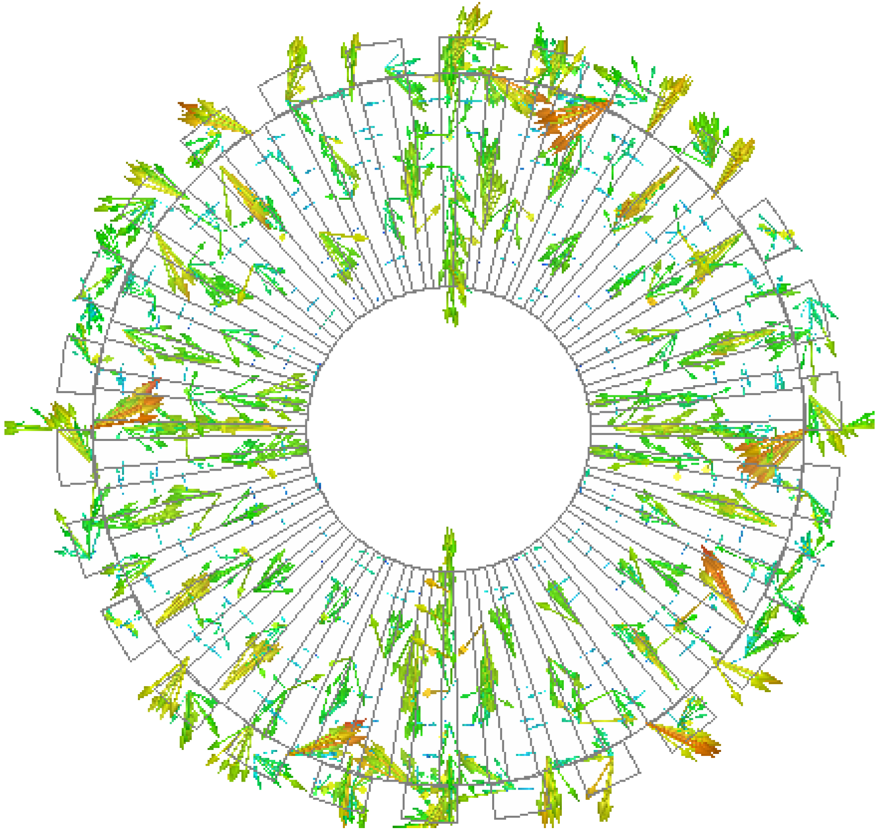
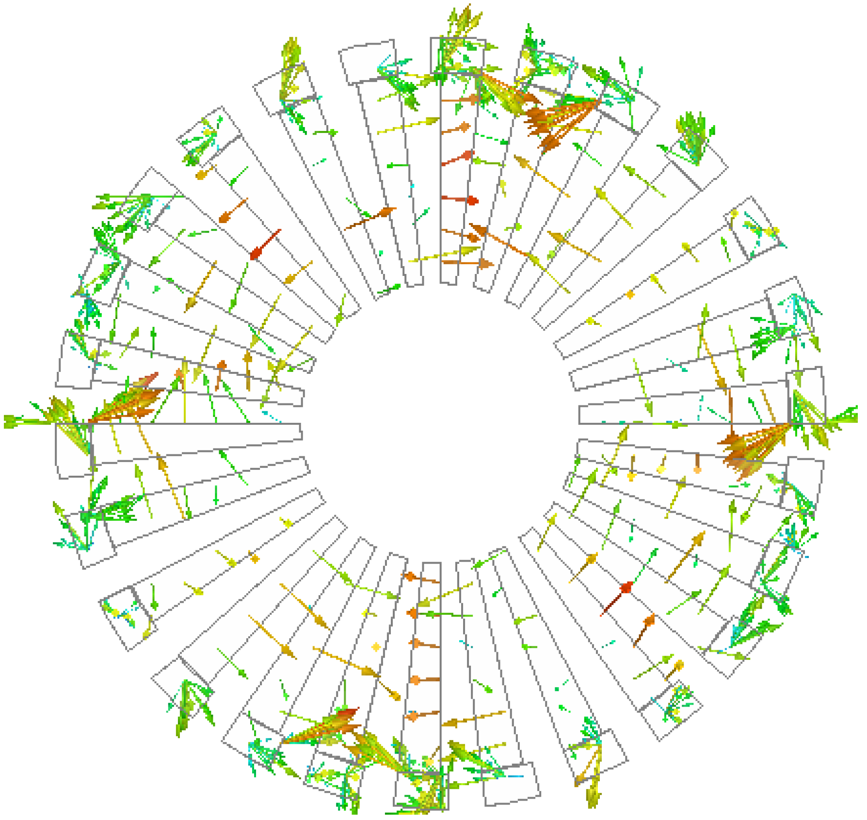
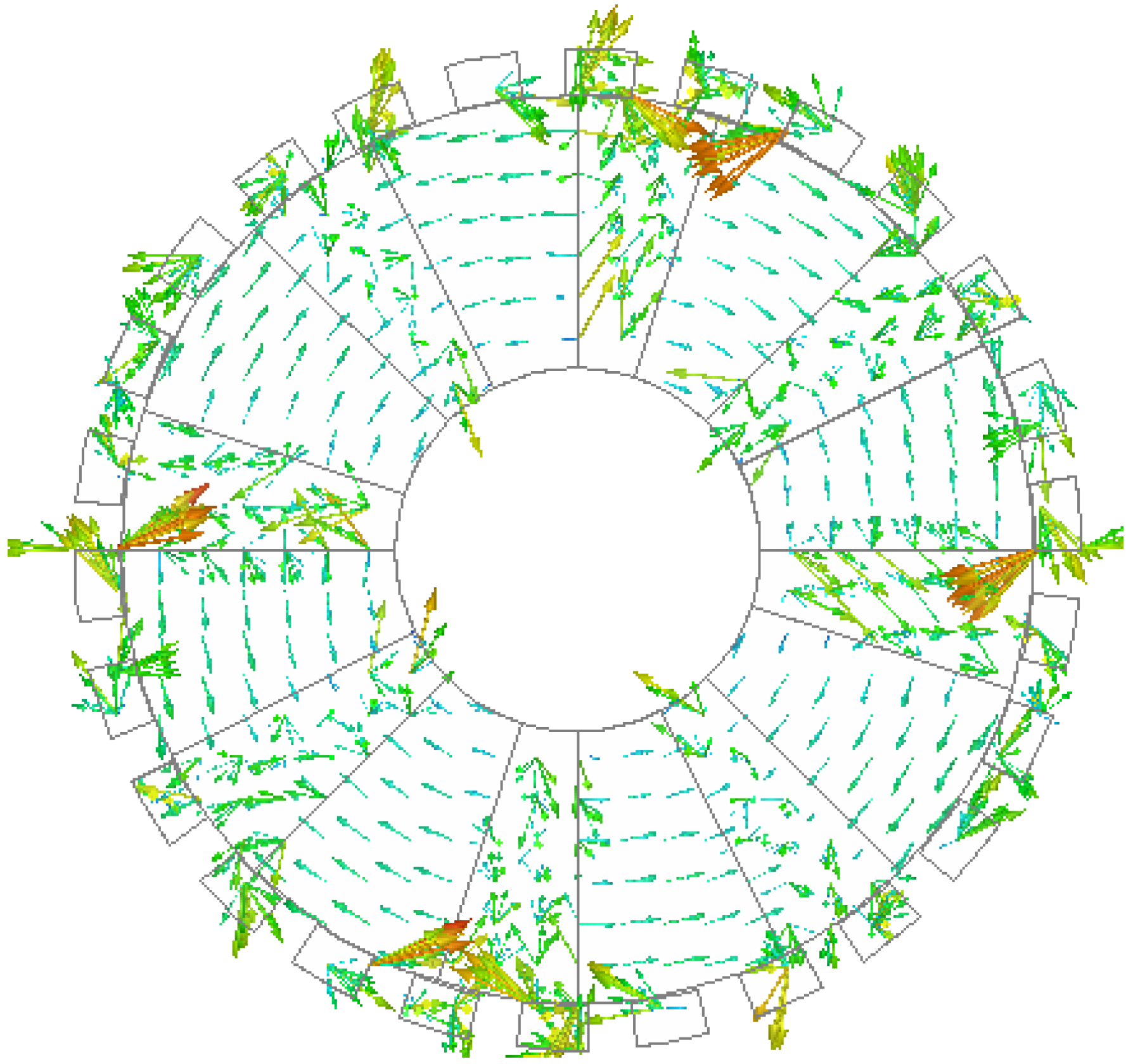
The magnetic field distribution of the proposed MG is determined using 3-D FEM. The electromagnetic torque is computed using virtual work method in the post processing of FEM [
13].
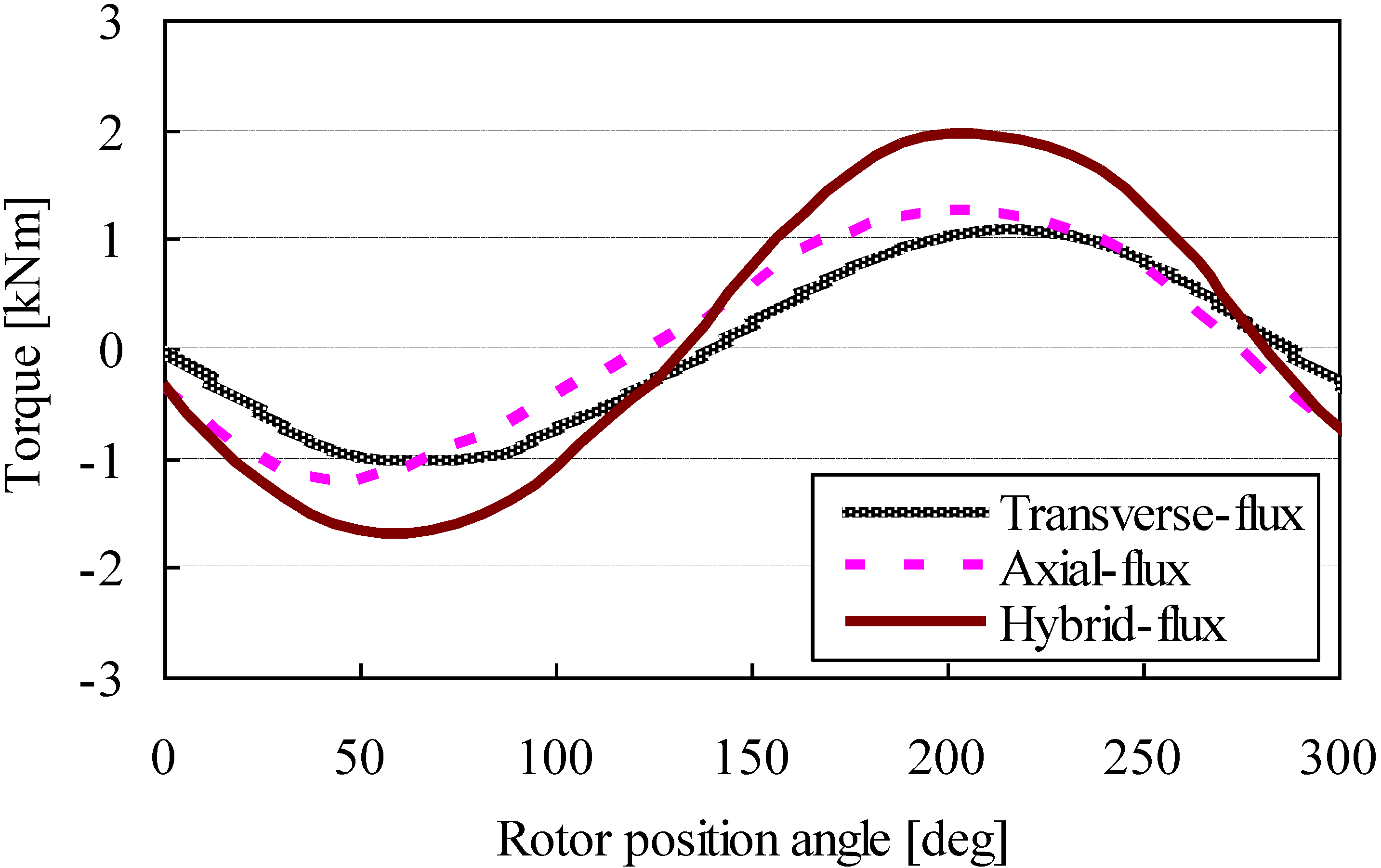
In order to evaluate the torque capability of the constructed MG, the torque-load angle characteristic is investigated by computing the electromagnetic torque on the low-speed rotor which rotates at a speed of 20 rpm when the high-speed rotor is locked [
14,
15,
16].
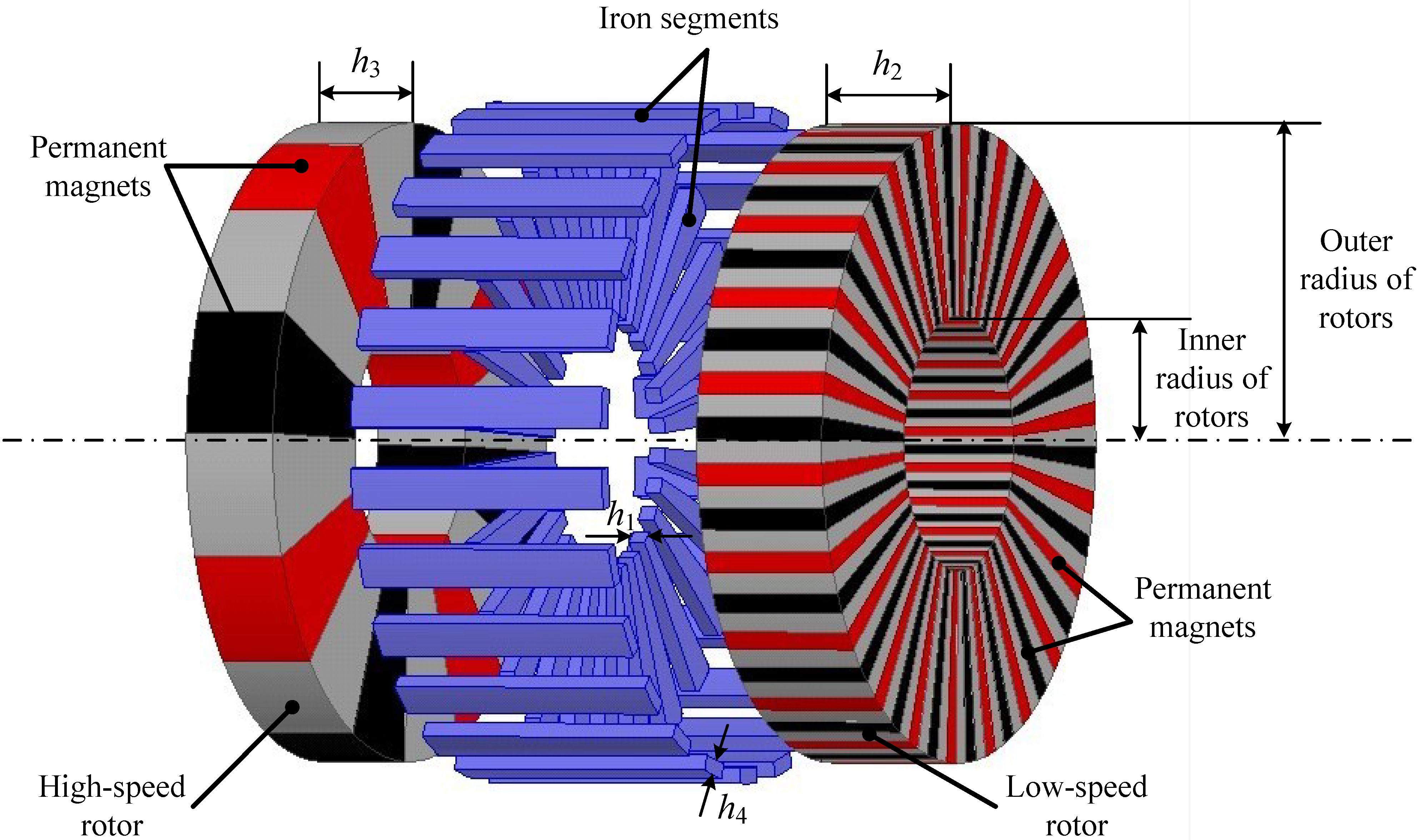
The configuration of the magnetic gear proposed in this paper is shown in
Figure 1. It has one high-speed rotor and one low-speed rotor arranged in parallel along the axial direction. The high-speed rotor and low-speed rotor have, respectively,
phigh and
plow pairs of rare-earth PM poles. It has specific stationary iron segments with
ns =
phigh +
plow pole pairs, outside of the two rotors, which constitutes a transverse-flux magnetic gear. It also has stationary iron segments with
pFe pole pairs between the two rotors, which constitutes an axial-flux magnetic gear.
Figure 1.
Proposed hybrid-flux magnetic gear.
Figure 1.
Proposed hybrid-flux magnetic gear.
The proposed structure is a combination of these two aforementioned conventional topologies and the space can be properly and fully utilized. When the rotors rotate, the iron segments will modulate the transverse and axial magnetic fields at the same time, and the capacity of the torque being transmitted can be enhanced significantly.
For the case in this paper, the high-speed rotor has
phigh = 4 pole pairs, the low speed rotor has
plow = 22 and the number of stationary iron segments is
ns = 26. After the pole combination is chosen, the gear ratio is then determined as
Gr = −22/4 = −5.5. The geometric parameters of this hybrid-flux MG are listed in
Table 1. With the help of the 3-D finite element analysis the performance of the MG is numerically analyzed.
Table 1.
Initial design parameters of the proposed MG.
Table 1.
Initial design parameters of the proposed MG.
| Design parameters | Values |
|---|
| Number of pole pairs of high-speed rotor phigh | 4 |
| Number of pole pairs of low-speed rotor plow | 22 |
| Number of pole pairs of iron segments ns | 26 |
| Outer radius of rotors [mm] | 150 |
| Inner radius of rotors [mm] | 60 |
| Thickness of middle iron segments h1 [mm] | 8 |
| Axial length of low-speed rotor h2 [mm] | 65 |
| Axial length of high-speed rotor h3 [mm] | 45 |
| Thickness of outer iron segments h4 [mm] | 10 |
| Air-gaps [mm] | 0.5 |
4. Analysis of Design Parameter
To find the effect of geometric parameters on the output torque capacity, eight design variables are studied. They are the axial length of the two rotors and the corresponding ratios of PM to pole pitch, the thickness of the two sets of iron segments and the corresponding ratios of iron to pole pitch.
Golden Section (GS) Search is a method that shrinks continually the known range of the optimum value of a monotonic function in finding its optimal value [
17,
18]. The algorithm keeps the spacing between three points with golden section properties. Here, the axial length of low-speed rotor
h2 and the axial length of high-speed rotor
h3 are optimized using GS search method. That is assuming
h3 is infinite and one finds the minimum
h2 for maximum torque by changing the value of
h2 using GS method. After
h2 is determined, the value of
h3 is changed in a similar way to find the minimum
h3 at which the maximum torque is reached.
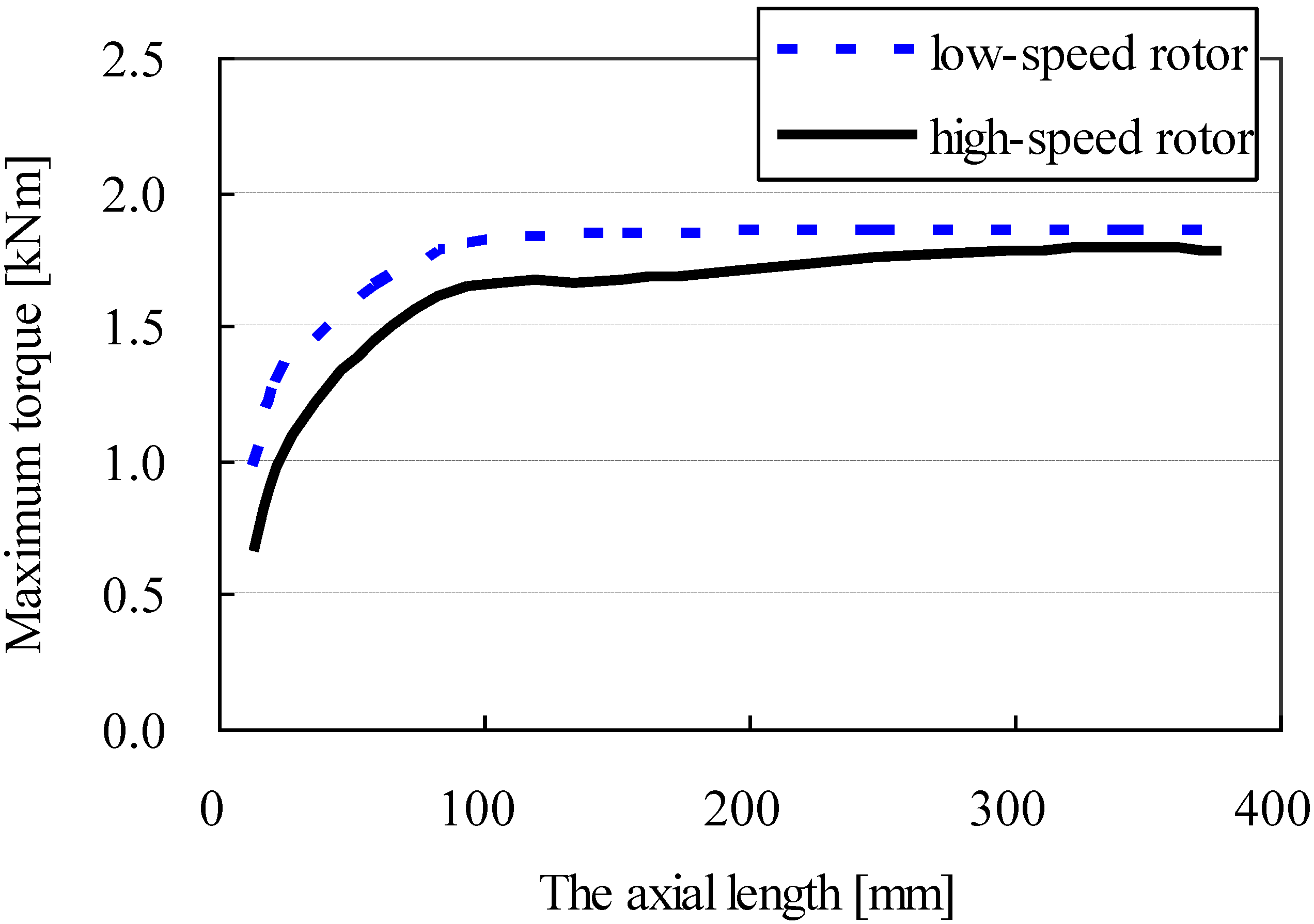
Figure 2 shows the maximum torque versus the axial length of the two rotors. It can be found that if the axial length of the rotors is larger, a higher torque can be achieved. But when the rotor length reaches a certain value, the torque will not be greatly improved even if the length continues to increase. On the contrary, it will increase the cost of this MG as excessive PM is used. Therefore, it is very necessary to find the most appropriate rotor length to ensure the maximum torque is realized with minimum PM usage.
Figure 2.
Maximum torque versus the axial length of rotors.
Figure 2.
Maximum torque versus the axial length of rotors.
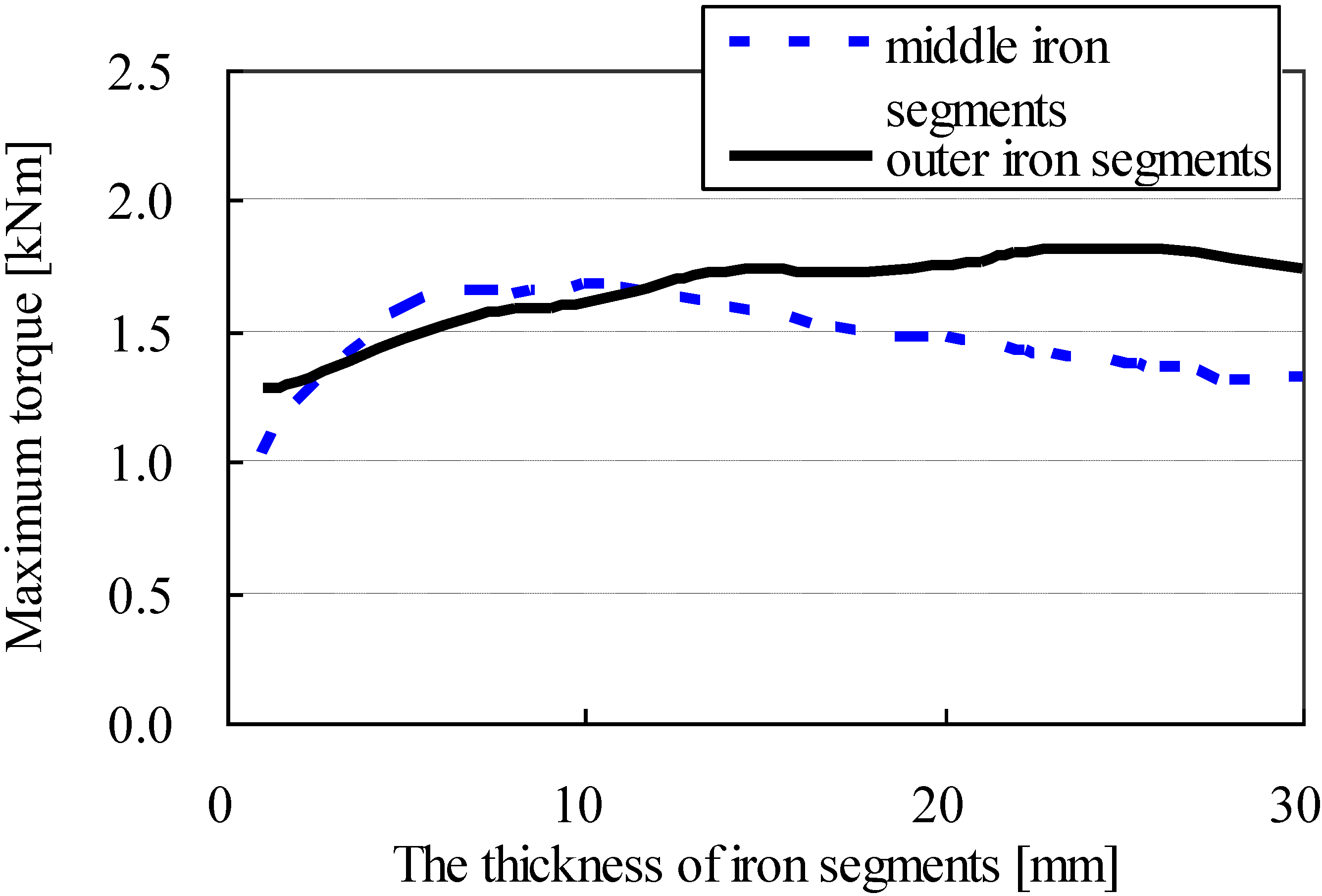
Figure 3 shows the maximum torque versus the thickness of two sets of iron segments. It can be seen that the maximum torque increases when the thickness of the middle iron segments is increased appropriately. But lower torque will be obtained if the thickness is too large due to the appearance of unduly long magnetic path. The effect of the thickness of the outer iron segments is that there is an increase in the maximum torque as the thickness increases. However, oversize thickness is needless because excessive PM is of little use to improve the torque. In this case, using materials with high saturation flux density is required.
Figure 3.
Maximum torque versus the thickness of iron segments.
Figure 3.
Maximum torque versus the thickness of iron segments.
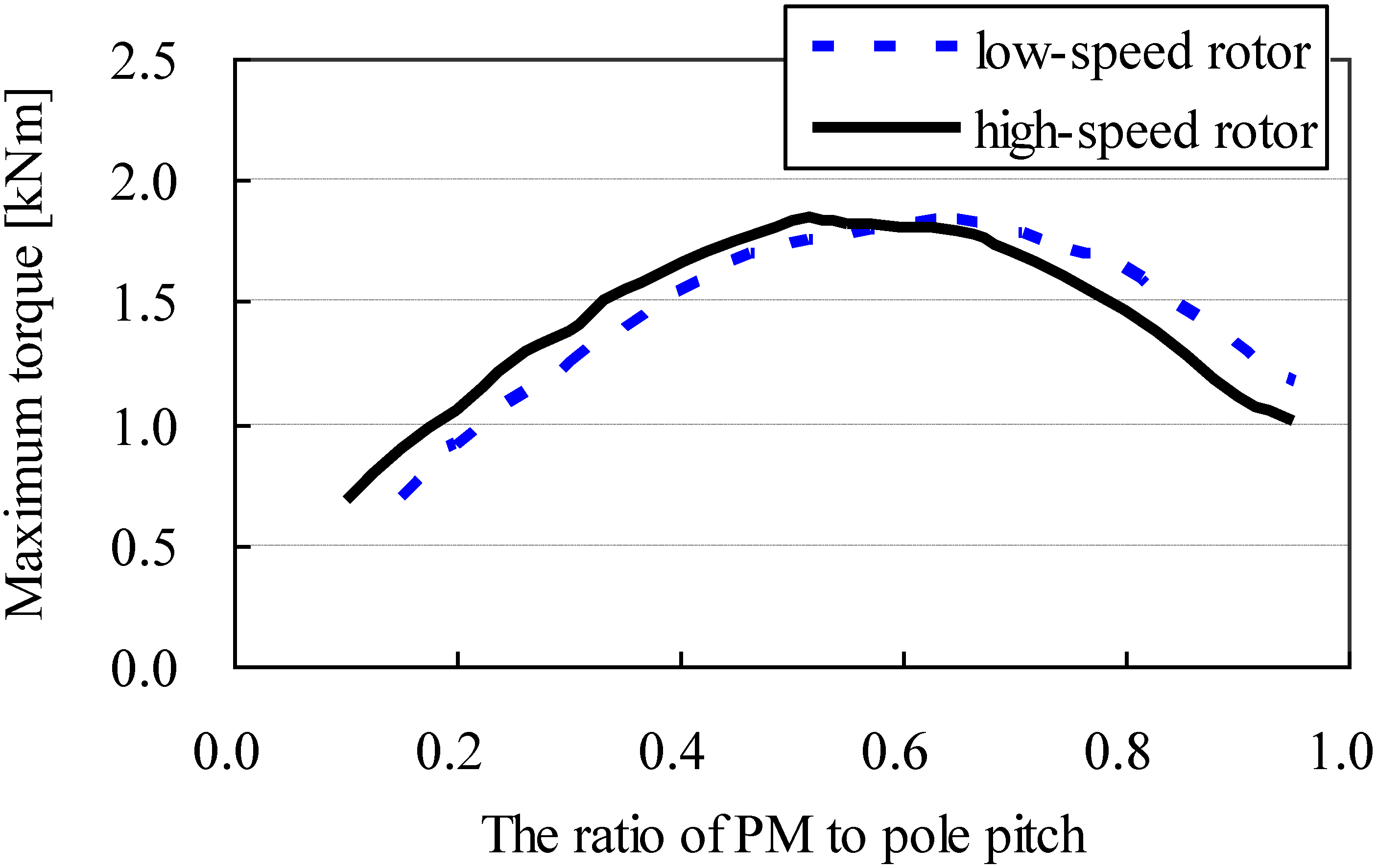
The effect of the ratios of PM to pole pitch of the two rotors on the maximum torque is shown in
Figure 4.
Figure 4.
Maximum torque versus the ratio of PM to pole pitch of rotors.
Figure 4.
Maximum torque versus the ratio of PM to pole pitch of rotors.
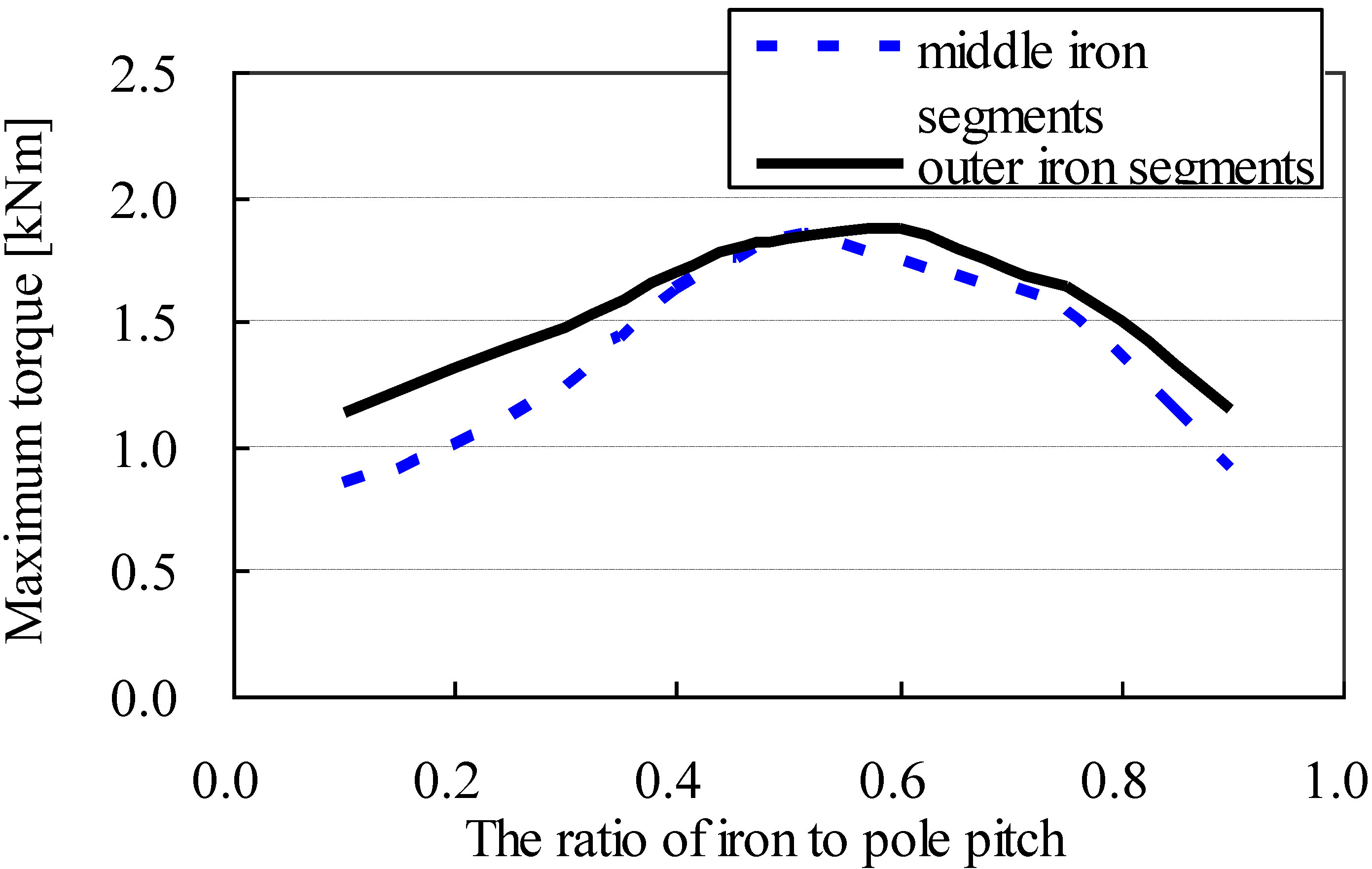
Figure 5 shows the maximum torque
versus the ratios of iron to pole pitch of two sets of iron segments.
Figure 5.
Maximum torque versus the ratio of iron to pole pitch of iron segments.
Figure 5.
Maximum torque versus the ratio of iron to pole pitch of iron segments.
From
Figure 4 and
Figure 5 one can find that choosing appropriate ratios of PM to pole pitch and iron to pole pitch can produce preferable maximum torque. The analysis above illustrates that all the eight parameters have influence on the torque capacity of the MG. During the study, the correlations among the parameters have not been taken into consideration while they are studied simply by the sweeping method. So the structure obtained cannot achieve optimal torque performance. However, if one tries to optimize all the parameters at the same time, it will take a lot of computing time as 3-D FEM is required for the torque computation.
5. Design Method and Results
A global optimization method is used to determine the sizes of the gear. As 3-D FEM is required to compute the electromagnetic torque, it is essential to reduce the computing time. In this paper the design parameters are divided into several groups based on the sensitivity analysis among them [
19]. The optimization of these parameter groups can be processed in series, which can significantly reduce the number of objective function computation.
The sensitivity analysis is to study the correlation between the design parameters. If they are not related, they will be optimized separately using the sweep method directly. Otherwise, they should be optimized simultaneously using the response surface methodology (RSM).
In this embodiment, the specific analysis process is as follows. As shown in
Table 2, it is assumed that there are two variables
x1 and
x2, and the corresponding maximum torque is
T. If
x1 has a small increment while
x2 remains unchanged, the obtained maximum torque is
T1. Similarly if
x2 has a small increment while
x1 stays the same, the maximum torque is
T2. When there are little increments in both
x1 and
x2 the torque is
T12. By calculating the difference between the three torques and
T respectively, the relationship among them can be analyzed. If the value |Δ
T12-Δ
T1-Δ
T2| is within the margin of error, then the two variables are uncorrelated. On the contrary, they are correlated. By using this method, the correlation between two parameters can be worked out.
Table 2.
Sensitivity analysis.
Table 2.
Sensitivity analysis.
| Design parameters | Torque | Torque increment |
|---|
| x1 x2 | T | |
| x1 + Δx1 x2 | T1 | Δ
T1 = T1 − T |
| x1 x2 + Δx2 | T2 | Δ
T2 = T2 − T |
| x1 + Δx1 x2 + Δx2 | T12 | Δ
T12 = T12 − T |
Response surface methodology explores the relationships between several explanatory variables and one or more response variables [
20]. The method was introduced by G. E. P. Box and K. B. Wilson in 1951. It allows individual effects of the k-factors to be estimated independently without (or with minimal) confounding. Also the orthogonality provides minimum variance estimates of the model coefficient so that they are uncorrelated.
An easy way to estimate a first-degree polynomial model is to use a factorial experiment or a fractional factorial design. This is sufficient to determine which explanatory variables have an impact on the response variable(s) of interest. Once it is suspected that only significant explanatory variables are left, then a more complicated design, such as a central composite design can be implemented to estimate a second-degree polynomial model, which is still only an approximation at best. However, the second-degree model can be used to optimize (maximize, minimize, or attain a specific target for) [
21,
22,
23,
24,
25].
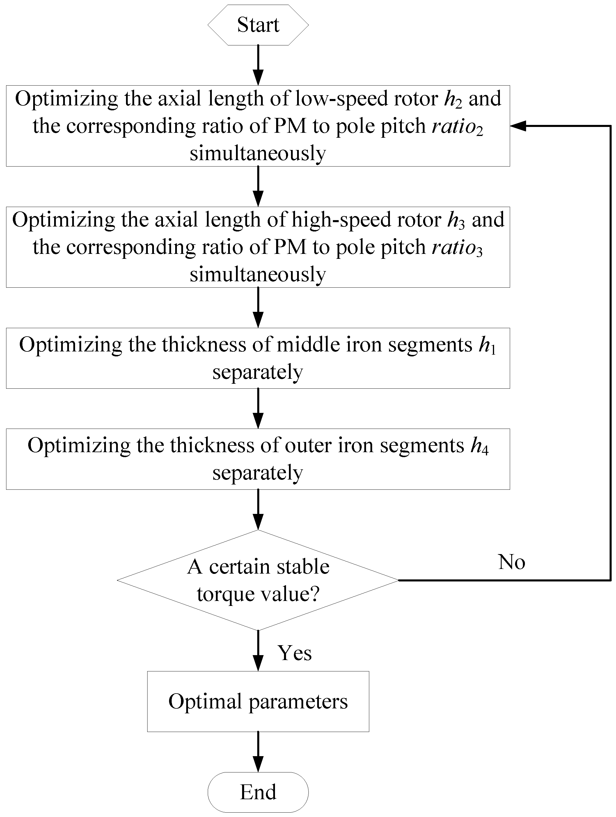
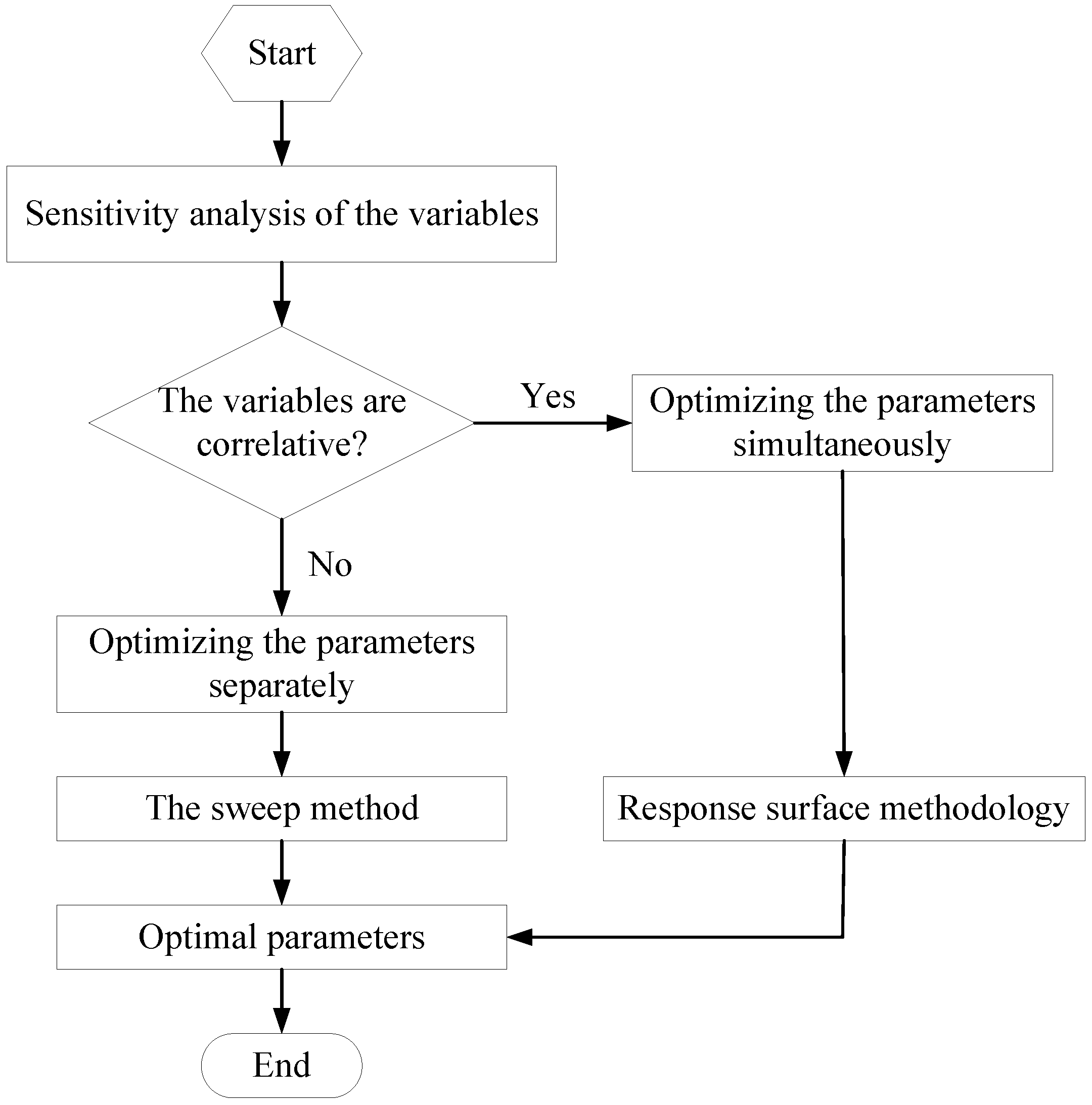
The parameter design flow chart is shown in
Figure 6. For the case studied in this paper, the specific parameter optimization flow chart is shown in
Figure 7. By using the parameter analysis described in the previous Section, it can be seen that the axial length of the rotors and the corresponding ratios of PM to pole pitch are correlated and they should be optimized simultaneously. The thickness of the two iron segments can be optimized separately and sequentially. In order to make the optimization more comprehensive, several iterations are done and a respond surface method is used.
Figure 6.
Parameter design flow chart.
Figure 6.
Parameter design flow chart.
Figure 7.
Specific parameter optimization flow chart.
Figure 7.
Specific parameter optimization flow chart.
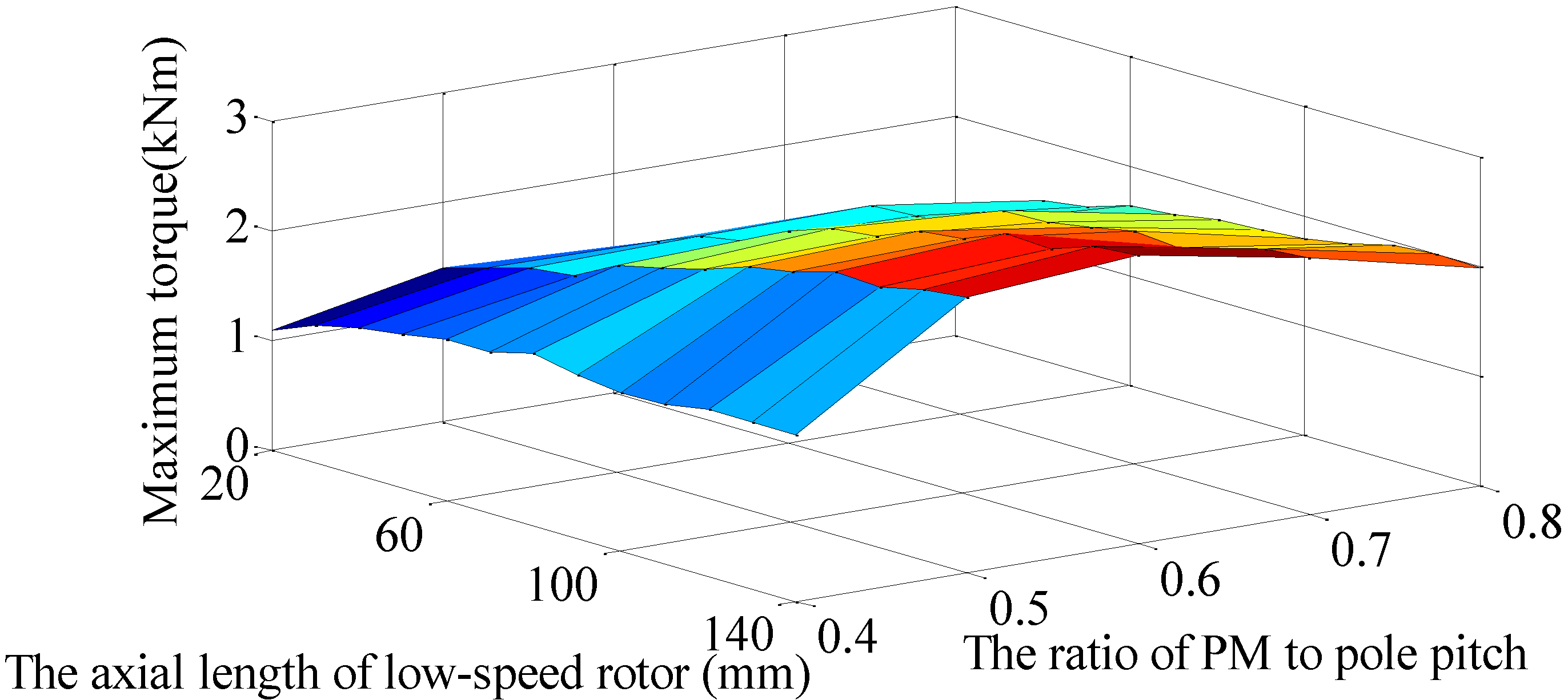
The effect of the axial length of the rotors and the corresponding ratios of PM to pole pitch on the maximum torque are shown in
Figure 8 and
Figure 9. The results are obtained using simultaneous analysis.
Figure 8.
The effect of the axial length of low-speed rotor and the corresponding ratio of PM to pole pitch on the maximum torque.
Figure 8.
The effect of the axial length of low-speed rotor and the corresponding ratio of PM to pole pitch on the maximum torque.
Figure 9.
The effect of the axial length of high-speed rotor and the corresponding ratio of PM to pole pitch on the maximum torque.
Figure 9.
The effect of the axial length of high-speed rotor and the corresponding ratio of PM to pole pitch on the maximum torque.
By the aforementioned analysis, the final design parameters of the proposed hybrid-flux MG are listed in
Table 3.
Table 3.
Final design parameters of the proposed MG.
Table 3.
Final design parameters of the proposed MG.
| Design parameters | Values |
|---|
| Axial length of low-speed rotor [mm] | 110 |
| The ratio of PM to pole pitch of low-speed rotor | 0.6 |
| Axial length of high-speed rotor [mm] | 90 |
| The ratio of PM to pole pitch of high-speed rotor | 0.6 |
| Thickness of middle iron segments [mm] | 10 |
| The ratio of iron to pole pitch of middle iron segments | 0.5 |
| Thickness of outer iron segments [mm] | 15 |
| The ratio of iron to pole pitch of outer iron segments | 0.6 |


