Article

Research on the Torque and Back EMF Performance of a High Speed PMSM Used for Flywheel Energy Storage

School of Automation, Beijing Institute of Technology, Beijing 100081, China
*
Author to whom correspondence should be addressed.
Energies 2015, 8(4), 2867-2888; https://doi.org/10.3390/en8042867
Submission received: 3 December 2014 / Revised: 7 April 2015 / Accepted: 7 April 2015 / Published: 15 April 2015

Abstract

:
Due to advantages such as high energy density, high power density, rapid charge and discharge, high cyclic-life, and environmentally friendly, flywheel energy storage systems (FESs) are widely used in various fields. However, the performance of FES systems depends on the performance of a high speed machine, therefore, the design and optimization of a high efficiency and high power density machine are very crucial to improve the performance of the whole FES system. In this paper, a high speed permanent-magnet synchronous machine (PMSM) is researched. Considering the requirement of low torque ripple in low speed and loss caused by back electromotive force (EMF) harmonics, the electromagnetic performance is improved from points of view of slot/pole matching, magnetic-pole embrace with the finite element method (FEM). Furthermore, the magnetic-pole eccentricity, the slot opening, the thickness of PM and air-gap length are also optimized with Taguchi method. The electromagnetic performance, such as torque ripple, cogging torque, average torque and back EMF wave are much improved after optimization. Finally, experiments are carried out to verify the calculated results.

1. Introduction

With the rapid development of society and the economy, higher requirements are put forward for energy use, which include more reliability, more flexibility, more efficiency, more adaptability to various actual application situations, etc. Energy storage is a preferable way to solve the energy crisis problem and enable a sustainable energy future [1,2]. There are five main energy storage technologies, including storage batteries, super-capacitors, pumped storage, compressed air energy storage (CAES) and flywheel energy storage (FES) [3,4]. Table 1 shows a comparison between the five storage technologies [5,6,7,8]. As is seen from the Table, it is obvious that FES has the advantages of high power density, high storage density, rapid charge and discharge, easy installation and maintenance, high cyclic-life, and being environmentally friendly. Therefore, the FES has broad application prospects.
Table 1. Comparison of five storage technologies.
IndexSuper-CapacitorCAESPumped StorageStorage BatteryFES
Efficiency (%)~90<50~60~70~90
Storage densityHighHigh-MiddleHighest
Power densityHighMiddle-MiddleHighest
ModularityNoNoNoYesYes
Service life(years)10510520
Charge time unitHourHourHourHourMinute
PollutionNoYesYesYesNo
Build cycle unitYearYearYearMonthWeek
In recent years, the process of application of FES has been accelerated by the development of power electronic technology, motor/generator integrated technology, control technology, bearing technology and materials technology [9,10,11]. FESs are widely applied in various fields, such as power system applications, transportation applications, pulsed power applications, uninterrupted power supply (UPS) applications, space applications and military applications, etc. As for power system applications, the FES can be used for power regulation between utilities in the power grid [12,13,14,15,16]. For space applications, the FES can supply energy storage with the smallest mass and also can be used for attitude control for guidance of the craft [17,18,19]. For UPS applications, the FES system can serve as an UPS to supply energy for vital loads, such as hospitals, central computer rooms, government agencies, etc. [20,21,22]. As for military applications, the FES system can supply short high power bursts for electromagnetic cannon [23]. The aforementioned applications of FES show that FES plays an important role in modern industry and economy.
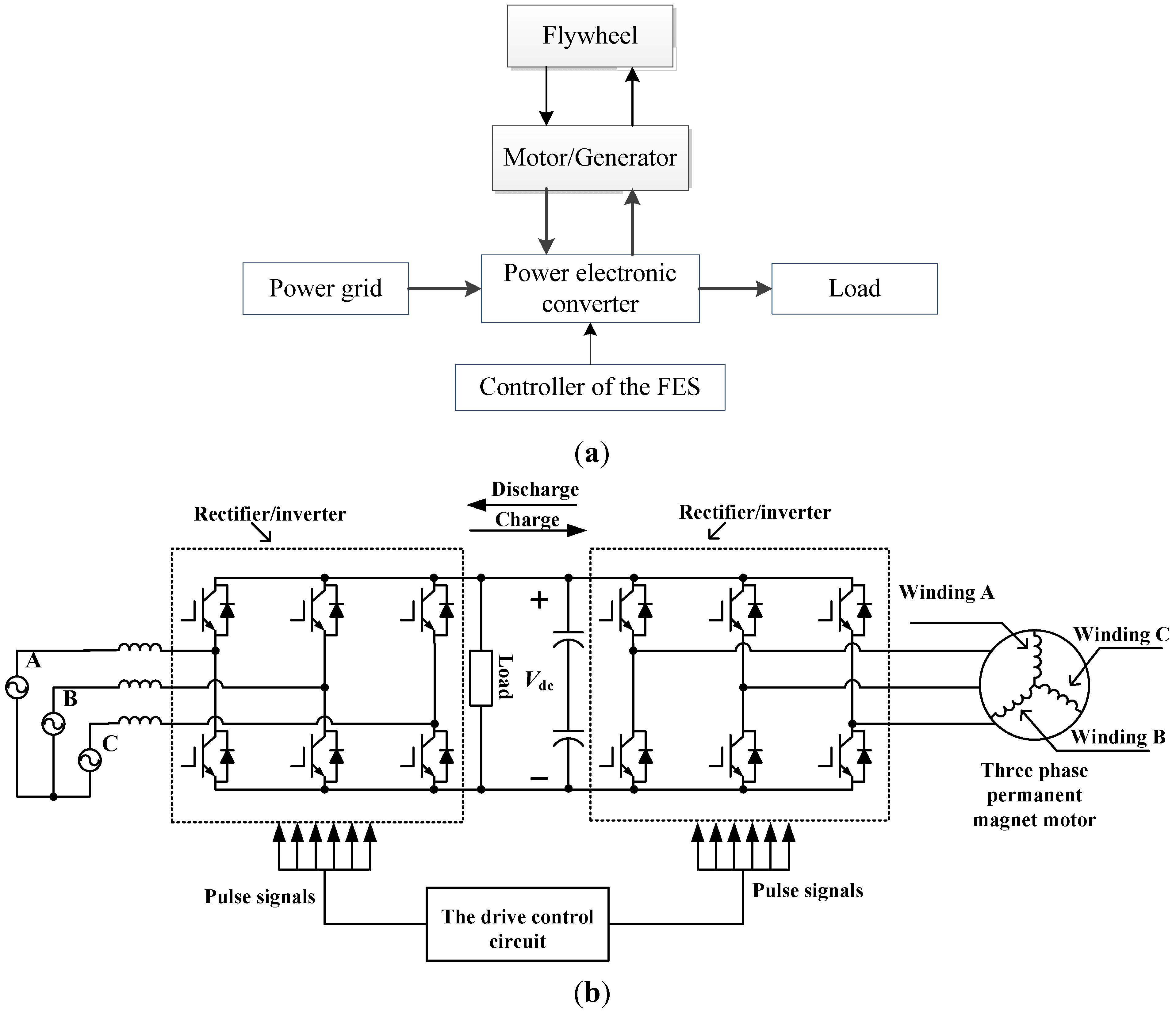
As shown in Figure 1a, a FES system mainly consists of four parts: flywheel, motor/generator, power electronic converter and controller [15,17]. The flywheel is coaxially connected with the shaft of the motor/generator. When the motor/generator operates as a motor, the system is charged and electric energy is transformed into mechanical energy by the flywheel. When electric energy is needed, the motor/generator will operate as a generator and the mechanical energy stored in the flywheel will be transformed into electric energy through power electronic converter. The drive circuit is shown in Figure 1b. As shown in this figure, the left and right rectifier/inverters that are controlled by the drive circuit controller work as rectifier and inverter, respectively, during the charging stage, and the power flows to the load and flywheel. During the discharging stage, the right rectifier/inverter works as a rectifier, while the left rectifier/inverter can work as a rectifier or an inverter depending on the load requirements. As is known, a multilevel converter can reduce the harmonics in the output voltage. Besides the converter topology shown in Figure 1b, the circuit topologies of diode-clamped multilevel inverter, capacitor-clamped multilevel inverter and cascaded inverter can be used in a FES [24]. Furthermore, modulation strategies, such as sinusoidal pulse-width modulation (SPWM) and space-vector modulation (SVM) can be used to obtain more sinusoidal output voltage.
The FES system stores kinetic energy when it works. The amount of stored energy Ek is defined by the following mechanical relationship:
E k = 1 2 J ω 2
where J is the inertia of the flywheel and rotor, ω is the rotational speed of flywheel or rotor. It is obvious that high rotational speed of the rotor can increase the energy density. The performance of the high speed machine has much influence on the FES system. So this paper is written from aspect of machine design.
Figure 1. (a) System block diagram of the FES; (b) drive circuit.
Energies 08 02867 g001
The permanent-magnet synchronous machine (PMSM) is favorable for use as a motor/generator in FES, because the PMSM has the advantages of high efficiency, high power density and high power factor, and so on. However, a lot of attention has been focused on the loss calculation and thermal analysis of the high speed machine [25,26,27,28,29,30,31,32,33]; in [25,26,27], a calculation method for the harmonic iron loss based on the combination of 2D and 3D FEMs is proposed; the iron loss and copper loss of a high speed PMSM that can operate at a speed of 60,000 rpm are analyzed and calculated in [28]; in [29], a fast hybrid method considering the factors of end effect and pulse-width modulation harmonics is proposed to calculate the iron loss; loss and thermal characteristics of a high speed PMSM based on the FEM are analyzed in [30,31,32]; in [33], a combined network and computational fluid dynamic (CFD) method is used for the thermal analysis. However, considering that the high speed machine used for FES system should start easily and run stably, the machine should have good torque performance. In addition, considering that FES system should have low iron loss at no load, air-gap magnetic field harmonics, which can be reflected by the back electromotive force (EMF) harmonics, will cause high losses in the stator core, rotor core and permanent magnets at high speed [34,35,36,37]. Furthermore, when the FES works under discharging or charging conditions, the back EMF waveform must also be closer to a sine wave and have as few harmonics as possible. Thus the torque performance and the back EMF have received much attention in this paper. The rotor structure can influence the back EMF and torque performance of a high speed machine. Ref. [28] adopted surface PMs while ref. [27] adopted interior PMs. This paper will compare the surface PMs with interior PMs from aspects of torque performance and back EMF harmonics. Numerous methods have been researched for reducing cogging torque, torque ripple and back EMF harmonics to optimize the design of PMSMs [38,39,40,41,42,43,44,45,46,47,48,49,50,
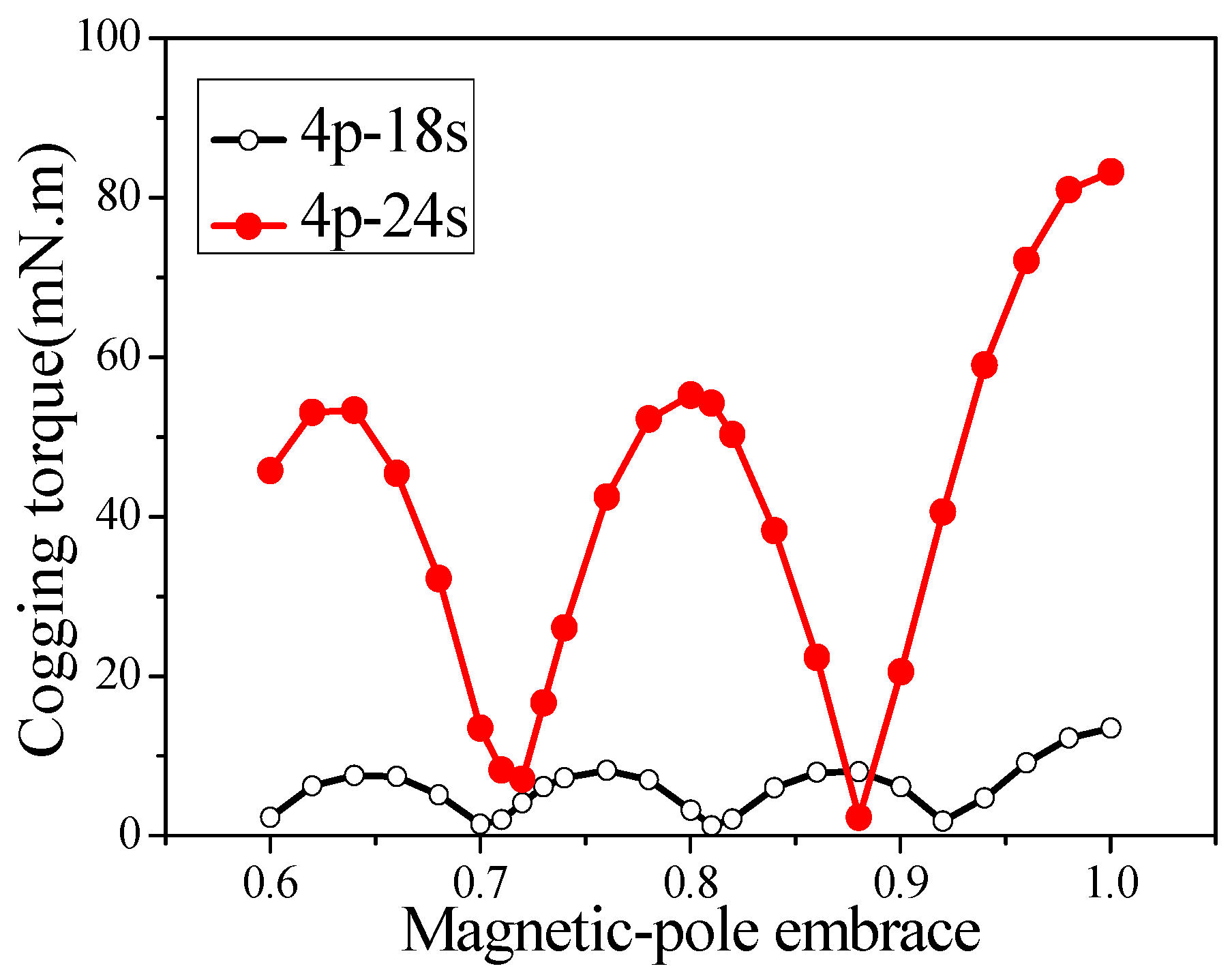
51]. A fractional number of slots per pole is an effective method. The larger the least common multiple of slots and poles is, the smaller the cogging torque is [38,39]. However, these works don’t consider the influence on the back EMF when the pole number is eight or above. In a high speed machine, a large pole number will cause high iron losses, so this paper focuses on the selection of slot number considering both torque performance and back EMF when the pole number has a constant value of four. The skewing can also effectively reduce both cogging torque and back EMF harmonics. The skewing can be designed at the stator, rotor or magnet [40,41]. However, compared with other methods, skewing has high manufacturing technology requirements, which will consequently increase the manufacturing cost. In addition, magnet shape has great influence on the torque performance and back EMF. Adopting a proper magnetic-pole embrace, cogging torque can reach zero in theory for surface machines and the back EMF harmonics can also be decreased. Bread-shape and stacked PMs are adopted to decrease the torque ripple in [42], but the torque ripple has been reduced at the expense of high manufacturing cost and the stacked PMs have the risk of falling off when the machine runs at high speed. Ref. [43] and ref. [44] only considered the back EFM wave, while ref. [45] only considered the cogging torque reduction. Ref. [
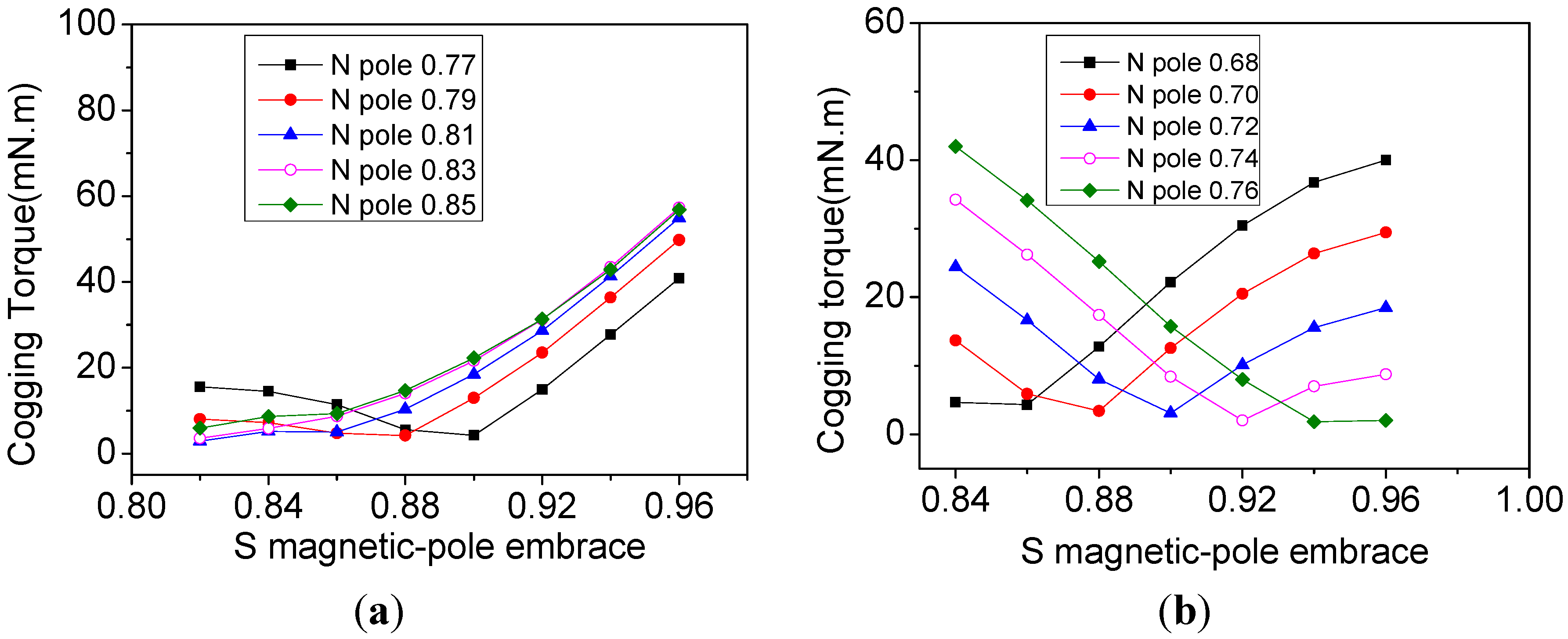
46] optimized the torque performance considering both magnetic-pole embrace and magnetic bridge width, and the magnetic-pole embrace of all poles is the same. This paper considers both torque performance and the back EMF during optimization. The N poles and S poles of the high speed machine that are set with different magnetic-pole embrace values will be researched. Sometimes the stator structure, such as teeth shape, is also optimized to minimize the cogging torque [47,48]. Besides, calculated optimization methods have attracted much attention in recent years. In [49], a genetic algorithm is used to optimize the discrete skew angle of PMs to reduce cogging torque based on 3D FEM. However, this work just optimized one parameter that has an influence on the torque performance and there are no experiments to verify the optimization result. In [50], three motor parameters are optimized at the same time to reduce the cogging torque by the non-dominated sorting genetic algorithm, but the optimization step length of each parameter is very small, which requires a large calculation time. The most important point is that it is impossible for a motor designer to use a complicated and time-consuming algorithm during the practical motor design. The Taguchi method [51,52] is a less time-consuming and multi-parameter method. Ref. [52] performed a robust design of EMF to reduce the effect caused by the manufacturing tolerances, and width, thickness and residual of PM are selected as the noise variables. In this paper, the magnetic-pole eccentricity, the slot opening, the thickness of PM and the length of air gap are optimized by using the Taguchi method for machine design. The tradeoff between back EMF and torque performance is considered. Experiments are conducted to verify the calculated results. This paper can provide useful references for a high speed machine designer.
This paper almost considers most of the factors that have an influence on the torque and back EMF performance. Meanwhile, a simple and effective optimization method, such as magnetic-pole embrace, is used for preliminary optimization, and a less time-consuming and multi-parameter method is adopted for further optimization. Sine-wave current is adopted to decrease the torque ripple and the harmonics of the back EMF wave. This paper is organized as follows: a rotor structure for the high speed machine is selected and the initial machine parameters are obtained in Section 2; based on the initial scheme, comprehensive analysis and optimizations are carried out by selecting an optimal slot/pole combination and magnetic-pole embrace with the finite element method (FEM) in Section 3; partial parameters, such as the magnetic-pole eccentricity, the slot opening, the thickness of PM and the length of air gap, are also optimized by using the Taguchi method in Section 4; a prototype high speed PMSM was manufactured and tested to validate the simulation results in Section 5.

2. Selection of Rotor Structure

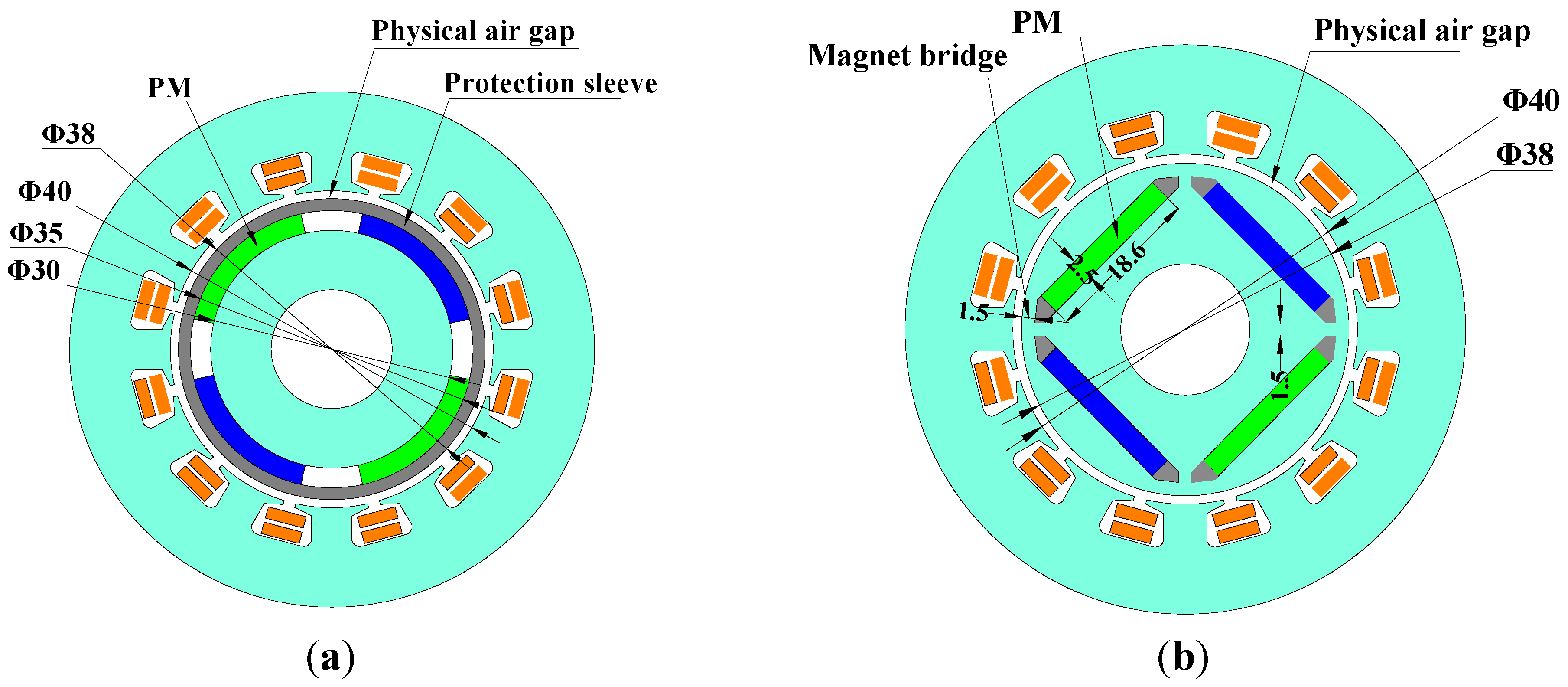
Both of the rotors with surface PMs (SPMs) and interior PMs (IPMs) can be used in high speed PMSMs. Both structures both adopt 12 slots-4 poles and the same stator parameters. Their rotor structures are different, but with the same volume of magnet materials, as shown in Figure 2.
Figure 2. Dimensions of the two rotors: (a) SPM and (b) IPM.
Energies 08 02867 g002
As for surface PMSM, a non-magnetic protection sleeve is usually adopted to protect the PMs from the high centrifugal force. In this paper, the total equivalent air gap length of the surface PMSM is 2.5 mm which includes the thickness of the protection sleeve (1.5 mm) and the physical air gap length (1 mm). Compared with the surface PMSM, the equivalent air gap length of an interior PMSM can be decreased to 1 mm without the protection sleeve. Besides, the magnetic bridge thickness of the interior PMSM is set to 1.5 mm to ensure the same mechanical strength as the surface PMSM. The PM width and PM thickness of the interior PMSM are 18.6 and 2.5 mm, respectively.
The surface PMSM and interior PMSM are compared by the finite element method (FEM), and the results are summarized in Table 2. It can be seen that although the interior PMSM has a smaller equivalent air gap length and the contribution of reluctance torque, it has lower average torque (Tav). In addition, the interior PMSM has higher cogging torque (Tcog), higher torque ripple (
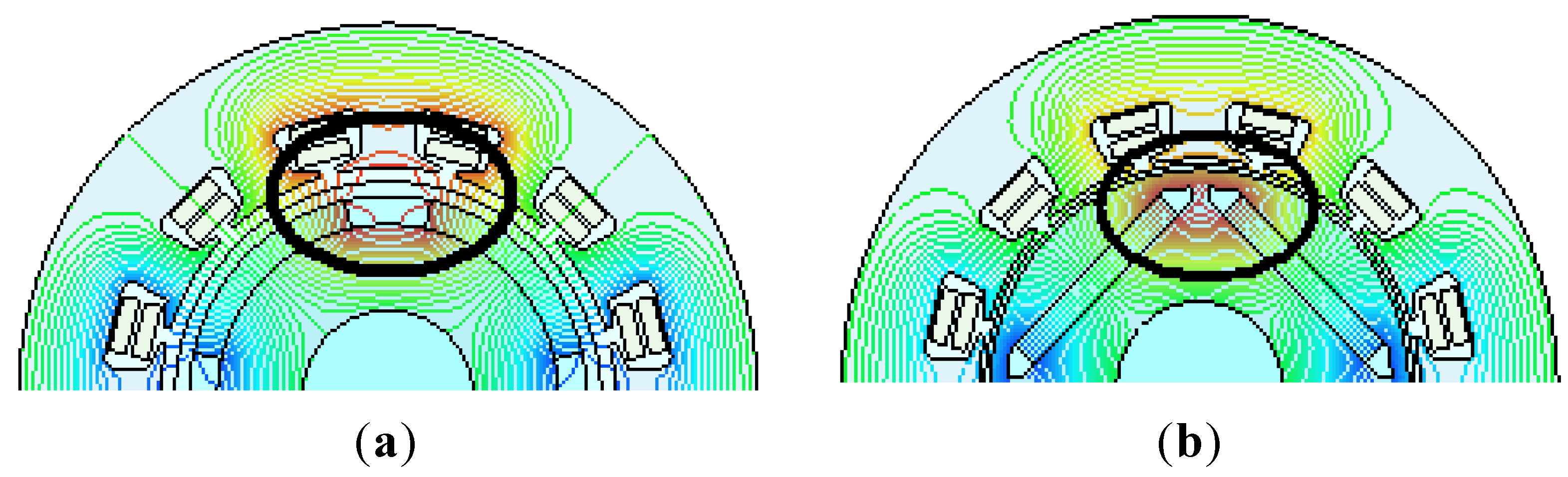
Trip) and higher total harmonics distortions (THD) than the surface PMSM. This is because the magnetic flux leakage (leakage coefficient of 1.6) of the interior PMSM is much higher than that of surface PMSM (leakage coefficient of 1.13) due to the large magnetic bridge thickness, as shown in Figure 3. Thus, the rotor structure with surface PMs is chosen for further research. The initial parameters of the PMSM with SPM rotor are listed in Table 3.
Table 2. Performances Comparison of IPM and SPM machines.
StructuresTavTripTcogTHD
IPM385 mN·m6.60%27.6 mN·m11.50%
SPM387 mN·m3.20%21.4 mN·m7.30%
Figure 3. Flux line distribution of the two structures: (a) SPM and (b) IPM.
Energies 08 02867 g003
Table 3. Initial parameters of the machine.
ParametersValueParametersValue
Magnet materialNTP42UHMagnet remanence (20 °C) (T)1.299
Pole number4Rated speed (rpm)30000
Rated power (kW)1Conductor per slot24
Length of core (mm)80Outer diameter of rotor (mm)35
Outer diameter of stator (mm)65Inner diameter of rotor (mm)15
Inner diameter of stator (mm)40Magnetic-pole embrace0.73
Thickness of magnet (mm)2.5Magnetic-pole eccentricity (mm)0
Thickness of protection sleeve (mm)1.5Slot opening (mm)1.5
Current density (A/mm2)6.4Air gap length (mm)1
Linear current density (A/cm)50Average air-gap flux density (T)0.636

3. Optimization of Pole/Slot Matching and Magnetic Pole Embrace

3.1. Pole/Slot Combination

Cogging torque is an important factor to torque characteristics. The cogging torque can be calculated as [53]:
T cog α = L ef B σ 2 C T μ 0 π ( R 2 2 R 1 2 ) × n = 1 K skn n sin ( n N L b 0 2 ) sin ( n N L α p π N p ) sin ( n N L α 1 2 n N L α s )
where μ0 is the permeability of air, Lef represents the effective axial length, Bδ represents magnetic flux density of air gap, R1 and R2 represent outer and inner diameter of air gap, Np represents pole number, NL represents the least common multiple (LCM) between Np and Ns, b0 represents the angle of slot opening, αp represents the magnetic-pole embrace, αs represents the angle of stator skew, α represents the rotor position, Kskn is the skewing factor, and CT is given by:
C T = N s N p / N L
where Ns represents slot number.
It can be seen from Equations (2) and (3) that the slot/pole combination can affect the coefficient CT which will further affect the cogging torque. Therefore, it is necessary to analyze the slot/pole combination to obtain low torque ripple. In this paper, three high speed PMSMs with different slot/pole combinations of 4 poles-12 slots (4p-12s), 4 poles-18 slots (4p-18s) and 4 poles-24 slots (4p-24s) are researched and compared. The three motors differ in the number of slots and conductors per slot, but they have the same number of series turns per phase, outer diameter of stator and other parameters as listed in Table 3. The torque characteristics results are shown in Table 4.
Table 4. Performances of machine with different slot-pole combination.
Slot/Pole Combination4p-12s4p-18s4p-24s
Tcog (mN·m)21.34.17.0
Tav (mN·m)387.9421.4413.9
Trip3.2%1.6%1%
THD7.3%4.1%3.6%
Based on the data, the 4p-12s type is abandoned because of its lowest torque (387.9 mN·m) and highest torque ripple (3.2%). The 4p-18s has a higher average torque and higher torque ripple than the 4p-24s version, while the cogging torque is smaller than that of the 4p-24s type. The torque ripple contains cogging torque and electromagnetic pulsation, which has relationships with the THD of EMF. The phenomenon that the 4p-18s has a smaller cogging ripple but a higher torque ripple can be explained by the higher THD of the 4p-18s (4.1%) than that of the 4p-24s (3.6%). Considering all these factors, it is difficult to select a better structure between 4p-18s and 4p-24s, therefore, further analysis is needed.

3.2. Optimization of Traditional Magnetic-Pole Embrace

As to PMSM, both the amplitude and distribution of the air-gap magnetic field will be affected by changing of the magnetic-pole embrace, which will further influence the torque characteristics. It can be seen from Equation (2) that the magnetic-pole embrace also has an influence on cogging torque. It can be analyzed that the cogging torque will be zero in theory if the magnetic-pole embrace satisfies the flowing equation:
sin ( n N L α p π N P ) = 0
The optimal theoretical magnetic-pole embrace will be calculated and shown as:
α p = N L / N P k N L / N P
where k is positive integer below the value of NL/Np.
Therefore there should be some magnetic-pole embraces making the cogging torque and torque ripple the smallest. In order to ensure the magnetic flux per pole and the average torque, the magnetic-pole embrace is varied from 0.6 to 1.0. The trends of average torque and cogging torque of both 4p-18s PMSM and 4p-24s PMSM are calculated by FEM, as shown in Figure 4 and Figure 5. It can be seen that with the increase of magnetic-pole embrace, average torque continues increasing. In addition, the 4p-18s has a higher average torque for the same magnetic-pole embrace. However, the cogging torque fluctuates with the increasing magnetic-pole embrace. The theoretical and simulated optimal values of αp are calculated and summarized in Table 5. As is seen from Figure 5 and Table 5, the 4p-18s has three optimal points (0.71 0.81 and 0.92) and 4p-24s has two optimal points (0.72 and 0.88) to minimize the cogging torque, which is consistent with the theoretical analysis. It also can be seen that the simulated optimal magnetic-pole embrace values are a little higher than the theoretical values, which is due of the neglect of magnetic flux leakage in Equation (5).
The torque characteristics at the optimal points are summarized in Table 6. In order to obtain a better characteristic, two optimal points of 0.81 and 0.92 for 4p-18s PMSM and two optimal points of 0.72 and 0.88 for 4p-24s PMSM are selected for further research in the following section.
Figure 4. The trend of average torque with the magnetic-pole embrace increasing.
Energies 08 02867 g004
Figure 5. Influence of the magnetic-pole embrace on the cogging torque.
Energies 08 02867 g005
Table 5. The Optimal Magnetic-Pole Embrace.
Slot/Pole Combination4p-18s4p-24s
NL/Np96
Theoretical Value with fraction form8/9,7/9,2/3 (0.89,0.78,0.67)5/6,2/3 (0.83,0.67)
Simulated Optimal Value0.92,0.81, 0.710.88,0.72
Quantitative Difference0.03,0.03,0.040.05,0.03
Table 6. The torque characteristics at simulated optimal magnetic-pole embrace.
Slot/Pole Combination4p-18s4p-24s
Optimal Magnetic Pole Embrace0.710.810.920.720.88
Average Torque (m·Nm)418.3445.0461.8413.9449.0
Torque Ripple (%)1.40.21.51.00.6
Cogging Torque (m·Nm)2.01.21.87.02.3

3.3. Optimization of the Torque Characteristic with a Magnetic-Pole Embrace Combination

The machine may have better torque characteristics when the N poles and S poles of the machine are set with different magnetic-pole embrace values, which is shown in Figure 6. In this part, the combination of the N-pole and S-pole magnetic-pole embraces is optimized around the optimal magnetic-pole embraces obtained. In this process, all the N poles have the same magnetic-pole embrace and all the S poles have another magnetic-pole embrace. As for 4p-18s, the magnetic-pole embrace of the S poles varies from 0.82 to 0.96, while that of the N poles varies from 0.77 to 0.85; the corresponding cogging torques are shown in Figure 7a. As for 4p-24s, similarly, the magnetic-pole embrace of the S poles varies from 0.84 to 0.96 and that of the N poles from 0.68 to 0.76, and the corresponding cogging torques are shown in Figure 7b. From Figure 7, the points which have the smallest cogging torque are selected and summarized in Table 7. In addition, the torque characteristics at these points are calculated and listed in Table 7 and the torque characteristics at simulated optimal magnetic-pole embrace from Table 6 are also listed in the Table 7.
Figure 6. N poles and S poles of the machine with different magnetic-pole embrace values.
Energies 08 02867 g006
Figure 7. The trend of cogging torque with different magnetic-pole embrace: (a) 4p-18s PMSM; (b) 4p-24s PMSM.
Energies 08 02867 g007
Table 7. Torque characteristics with combinations of embrace.
Slot/Pole CombinationNo.N PolesS PolesTcog (mN·m)Tav (mN·m)Drav (%)Trip (%)Drrip (%)
4p-18s10.770.94.3447.33.11.490
20.790.884.2448.22.91.1026.2
30.810.822.9446.13.40.3775.2
40.830.823.6448.13.00.5960.4
50.850.825.9450.12.50.9536.2
60.810.811.2445.03.60.1987.3
7 (as reference)0.920.921.8461.80.01.490.0
4p-24s10.680.864.3422.78.50.5364.4
20.70.883.4427.87.40.4271.8
30.720.93.1431.66.50.4172.5
40.740.922.0439.34.90.3874.5
50.760.941.9439.64.80.4172.5
60.720.727.0413.910.440.9734.9
70.880.882.3449.02.80.5861.1
After the combinations, the 4p-24s PMSM with different magnetic-pole embrace gives a smaller cogging torque. For example, when the N and S poles have a magnetic-pole embrace of 0.76 and 0.94, respectively, the cogging torque is 1.9 mN·m and torque ripple is smaller (0.41%), but it is difficult to select an optimal scheme among these schemes directly. In order to evaluate torque characteristic more objectively, the decreasing rates of average torque (Drav) and torque ripple (Drrip) are calculated by taking the values in the No. 7 combination of the 4p-18s PMSM as the reference. A PMSM with the same magnetic-pole embrace 0.81 (No. 6 combination) is selected as the best scheme based on the compromise principle: the torque ripple and cogging torque are effectively reduced, but with the average torque loss being as little as possible.

4. Performance Optimization with the Taguchi Method

As is known, a high frequency of the fundamental and especially the harmonic magnetic field in a high speed machine will cause high losses in stator core, rotor core and permanent magnets. Considering that the back EMF waveform is the reflection of the magnetic field distribution, the THD of back EMF is studied. After the optimization in Section 3, the machine has good torque characteristics with an average torque of 445 mN·m and a torque ripple of 0.19%. However, the THD of back EMF is 9.72%, which is still high and will cause high losses. Thus a further THD optimization is needed based on the scheme obtained in Section 3.
In traditional methods, if there are N variables influencing EMF harmonics, average torque and the cogging torque, it is hard to take them into consideration together because of the complicated combinations. Here we give an example: if each variable has three levels of setting, there may be 3N design variations (N is the number of the variable) in the traditional method. The Taguchi method is a design optimization method. It can simplify the design process, reduce the calculation times, and provide a systematic and efficient approach to determine the optimum settings of multiple design parameters.
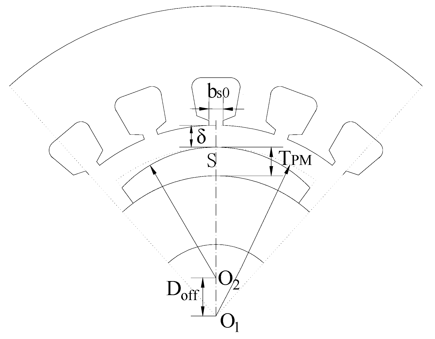
As shown in Figure 8, there are four main factors influencing the back EMF and torque characteristic: the magnetic-pole eccentricity (Doff), the slot opening (bs0), the thickness of PM (TPM) and the equivalent length of air gap (δ). The Doff is obtained by fixing O1 and moving O2. The minimum air gap is unchanged as Doff varying. The base value of the four factors are Doff = 0, bs0 = 1.5 mm, TPM = 2.5 mm, δ = 2.5 mm, respectively. They will be optimized with the Taguchi method.
Figure 8. Four parameters to be optimized: Doff, bs0, TPM, δ.
Energies 08 02867 g008

4.1. Optimization with Taguchi Method

There are three stages to perform the Taguchi method: (1) First of all, four factors A, B, C and D corresponding to Doff, bs0, TPM and δ are selected, the different levels of all factors are shown in Table 8; (2) Secondly, as shown in Table 9, the four factors at three levels are combined based on the orthogonal array (a standard OA L9), which is the most efficient orthogonal design.
Table 8. Levels of design variables.
Design Variable (mm)Level 1Level 2Level 3
A: Doff024
B: bs01.01.52
C: TPM22.53
D: δ2.32.52.7
Table 9. Results of nine models.
No.ABCDTcog (mN·m)TripTav (mN·m)THD
101.022.31.40.28%429.010.4%
201.52.52.51.10.19%445.09.72%
302.032.72.10.25%450.79.01%
421.02.52.70.60.18%406.26.52%
521.532.320.28%481.07.05%
622.022.51.20.29%375.56.41%
741.032.50.60.25%437.13.47%
841.522.70.10.28%331.31.48%
942.02.52.30.60.31%415.42.94%
The corresponding results of torque characteristics and the THD of back EMF for each combination scheme are calculated with FEM and also listed in Table 9; (3) Finally, the calculated results in Table 9 are analyzed through analysis of means (ANOM) and analysis of variance (ANOVA) to obtain optimal setting of parameters [54], which will be carried out in the following part.

4.2. Analysis of Results

4.2.1. Analysis of Means (ANOM)

ANOM is carried out to determine the best level combination to achieve optimal performance. From Table 9, it can be seen that all the cogging torque and torque ripple are very small, which can meet the requirements. Thus, the value of THD of back EMF and average torque will be emphatically analyzed in this part. The means of all results can be calculated as:
m = 1 9 i = 1 9 T ( i )
When the average effect of a design variable at one setting is considered, the average value of the design variable for one level of the setting factor can be calculated. For example, the average THD of setting factor B at level 2 (bs0 = 1.5 mm), which is only at No. 2, 5 and 8 in Table 9, is calculated as:
m B 2 = 1 3 i = 1 3 T THD (2) + T THD (5) + T THD (8)
Average THD and average torque for all levels of all factors can be obtained in a similar way. The THD and average torque result data, which is called the main factor effects, are listed in Table 10 and Table 11, respectively. As shown in Table 10 and Table 11, it is clear that the factor-level combination of A3-B2-C1-D3 (Doff = 4 mm, bs0 = 1.5 mm, TPM = 2 mm, δ = 2.7 mm) contributes to the minimization of THD, and the factor-level combination of A1-B1-C3-D1 (Doff = 0 mm, bs0 = 1.0 mm, TPM = 3 mm, δ = 2.3 mm) contributes to the maximization of average torque. In order to determine the factors that have significant effects on the machine performance, a mathematical method called ANOVA is used in the following section to obtain the ultimate optimal scheme for the high speed PMSM.
Table 10. THD for all levels of all factors.
Setting FactorsAiBiCiDi
i = 19.70%6.80%6.09%6.79%
i = 26.70%6.08%6.39%6.53%
i = 32.60%6.12%6.51%5.67%
Table 11. Average torque for all levels of all factors.
Setting FactorsAiBiCiDi
i = 1441.6424.1378.6441.8
i = 2421419.1422.2419.2
i = 3394.6413.9456.3396.1

4.2.2. Analysis of Variance

ANOVA does not analyze the results directly, but rather determines the relative importance of various design variables. In order to perform ANOVA, the sum of squares (SS), which is calculated based on the data of ANOM, should be obtained firstly. The SS for factor B can be calculated as:
S S FB = 3 i = 1 3 ( m B i m ) 2
SSF for A, C and D are obtained in the similar way. All the SS data for THD and average torque are summarized in Table 12. The effect ratio for each variable is calculated and also summarized in Table 12.
Table 12. Effects of various factors on machine performance indexes.
FactorsTHDAverage Torque
SSFFactor Effect RatioSSFFactor Effect Ratio
A76.295.8%3330.421.2%
B11.2%156.11%
C0.30.4%9101.157.9%
D2.12.6%3132.919.9%
Total79.6100%15720.5100%
As shown in Table 12, the factors A (Doff) and B (bs0) have larger effects on THD than average torque, while the factor C (TPM) and the factor D (δ) have larger effects on average torque than THD. Thus, based on the selected combination A3-B2-C1-D3 for THD and combination A1-B1-C3-D1 for average torque, the best combination of A3-B2-C3-D1 (Doff = 4 mm, bs0 = 1.5 mm, TPM = 3 mm, δ = 2.3 mm) is obtained to reduce the THD and increase the average torque as much as possible.
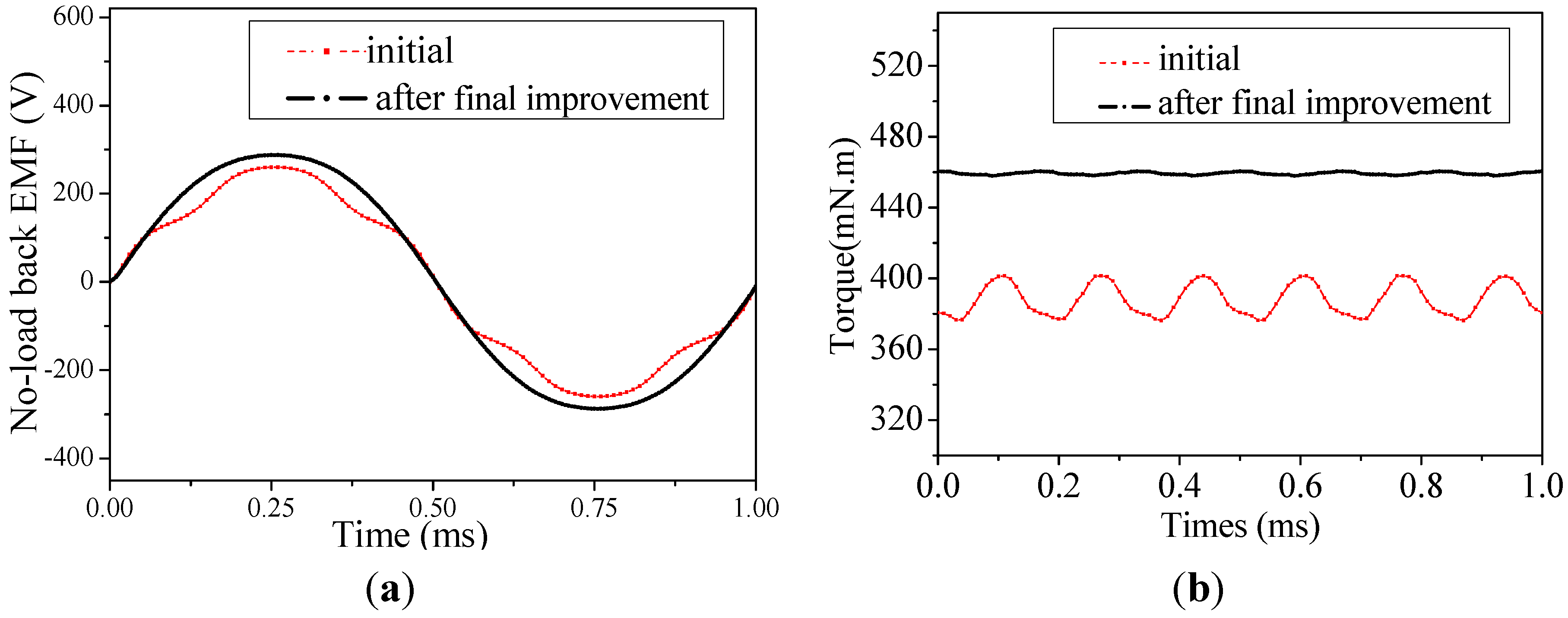
The performances of the initial and the final schemes are compared in Figure 9 and Table 13. After the final improvement, THD of the back EMF waveform decreases from 7.30% to 3.20% (by 50.3%), while cogging torque decreases from 21.36 to 1.04 mN·m (by 95.1%) and torque ripple decreases from 3.63% to 0.29% (by 90.9%). Meanwhile, the average torque increases from 387 to 459.2 mN·m (by 17.9%). It is validated that the electromagnetic performances of the machine are effectively improved. Furthermore, the rated q-axis reactance (Xq = 3.3938 Ω) and the rated d-axis reactance (Xd = 3.4263 Ω) are obtained using methods of back EMF by the FEM [55].
Figure 9. Comparison of electromagnetic performance of before and after optimization: (a) no-load back EMF waveform; (b) torque waveform.
Energies 08 02867 g009
Table 13. Comparison results.
PerformancesInitialFinalIncreasing Rate
Tav (mN·m)387456.317.9%
THD of back EMF7.30%3.63%−50.3%
Tcog (mN·m)21.361.04−95.1%
Trip3.20%0.29%−90.9%

5. Prototype Machine and Experiments

Based on the optimized scheme of the high speed PMSM, a prototype machine was manufactured, as shown in Figure 10. In order to evaluate the performance of the prototype machine, the no-load back EMF and torque characteristic are tested.
Figure 10. High speed PMSM prototype: (a) Rotor; (b) Stator; (c) Prototype.
Energies 08 02867 g010

5.1. No-Load Back EMF Test

Because of the lack of another high speed machine as the driving machine, the no-load back EMF test was limited to less than 5000 rpm. The measured and calculated no-load back EMFs at different speeds are shown in Figure 11. As can be seen from this figure, the calculated and measured back EMFs are in good agreement, which validates the results simulated by FEM. It can be seen from Figure 11b that the peak-peak value of the no-load back EMFs increases linearly with the speed increasing. Figure 11a shows the calculated and measured no-load back EMFs at 4860 rpm, and they are approximately sinusoidal. Especially, the THD of the measured back EMF is 2.59%, which is even smaller than the designed results. These validate the good design of the magnetic structure.
Figure 11. No-load Back EMF (a) at 4860 rpm and (b) versus different speed.
Energies 08 02867 g011

5.2. Torque Test

The torque characteristic at load is tested by a high- precision speed/torque sensor at very low speed, as shown in Figure 12 and Figure 13.
Figure 12. Test bench for measuring torque at load.
Energies 08 02867 g012
Figure 13. Measured torque at load.
Energies 08 02867 g013
The measured average torque and torque ripple at load are 473.9 mN·m and 0.34%, respectively. Because the load is not ideally steady, its ripple will superpose on the tested machine, so the measured torque ripple is a little higher than that by FEM. However, the torque ripple of the prototype machine is satisfactory and shows a good design.

5.3. Cogging Torque Test

In this paper, the method in [56] is used to measure the cogging torque. The measurement principle is shown in Figure 14. The balance weight is added to ensure that the metal bar acts on the digital gauge and the displayed values of the digital gauge are always positive. The cogging torque can be reflected in the value of the digital gauge when the stator rotates to different positions. Finally, based on the characteristic of zero average torque of the cogging torque, the cogging torque can be obtained by subtracting the average value of the measured data from every original measured data point. Moreover, the problem of the friction torque can be avoided by this way.
In order to obtain correct and precise results, there are several points to be noted: (1) both metal bars must be at the same height to the horizontal stand; (2) the precision of the digital gauge can reach 0.01 g or above to meet the requirement of cogging torque; (3) the stator can rotate a small angle every step; (4) the stator rotates in the same direction in a test process. The platform for measuring the cogging torque is shown in Figure 15.
Figure 14. The principle of measurement.
Energies 08 02867 g014
Figure 15. The platform for measuring the cogging torque: (a) Frame level; (b) Lathe and digital gauge; (c) Balance beam; (d) All devices.
Energies 08 02867 g015
As is known, the period of the cogging torque waveform is determined by the lowest common multiple (LCM) between the number of slots and the number of permanent magnets. In this paper, the prototype machine has four poles and 18 slots, so the LCM is 36. The period of the cogging torque waveform is 10° in mechanical angle. Figure 16 shows that the waveforms of cogging torque obtained by FEM and the actual measurement are in good agreement. The two waveforms have uniform trends and the peak value is very approximate in one period. An asymmetry air gap and low concentricity between stator and rotor may exist in the machine due to manufacturing errors, so the measured waveform fluctuates a little at some positions compared to the FEM waveform. Both the measured and simulated results indicate a small cogging torque of the prototype machine.
Figure 16. The measured and simulated cogging torque waveforms.
Energies 08 02867 g016

6. Conclusions

A high speed PMSM for use in a FES system is researched in this paper. By comparing with IPM rotor structure, the rotor structure with SPM is selected for the PMSM. Careful selections of slot/pole matching and magnetic-pole embrace are carried out. Slot/pole matching of 4p-18s and magnetic-pole embrace of 0.81 for N and S poles are obtained considering the torque characteristics. Furthermore, the torque characteristics and back EMF are optimized with Taguchi method on the aspects of magnetic-pole eccentricity, the slot opening, the thickness of PM and the length of air gap. The best combination of Doff = 4 mm, bs0 = 1.5 mm, TPM = 3 mm, δ = 2.3 mm is obtained after elaborate analysis. After optimization, the THD of the back EMF waveform is decreased by 50.3%, the cogging torque and torque ripple are decreased by 95.1% and 90.9%, respectively, and the average torque increased by 17.9%. A high speed PMSM prototype was manufactured. The back EMFs, torque characteristic at load and cogging torque are verified by experimental results. It is validated that Taguchi method is a good means to optimize the high-speed PMSM. This paper can provide good references for a high speed machine designer during practical design.

Acknowledgments

This work was supported in part by the National Natural Science Foundation of China under Project 51307008 and 51347009, in part by the Key laboratory for Intelligent Control & Decision of Complex Systems of Beijing Institute of Technology, in part by Ph.D. Programs Foundation of Ministry of Education of China under Project 20121101120024, in part by Basic Research Foundation of Beijing Institute of Technology under Grant 20110642015, 20120642013 and 20130642015, and in part by Excellent Young Scholars Research Fund of Beijing Institute of Technology.

Author Contributions

All authors contributed to this work by collaboration. Jing Zhao is the main author of this manuscript. Zhongxin Gu and Xiaobei Li assisted in the design of optimization methods to this study. Bin Li and Zhen Chen provided some useful suggestions in the construction of paper. The whole project was supervised by Xiangdong Liu. All authors revised and approved the publication.

Conflicts of Interest

The authors declare no conflict of interest.

References

  1. Roberts, B.; McDowall, J. Commercial successes in power storage. IEEE Power Energy Mag. 2005, 3, 24–30. [Google Scholar]
  2. Flynn, M.M.; McMullen, P.; Soliks, O. Saving energy using flywheels. IEEE Ind. Appl. Mag. 2008, 14, 69–76. [Google Scholar] [CrossRef]
  3. Gelman, V. Energy storage that may be too good be true: Comparison between wayside storage and reversible thyristor controlled rectifiers for heavy rail. IEEE Veh. Technol. Mag. 2013, 8, 70–80. [Google Scholar] [CrossRef]
  4. Suvire, G.O.; Mercado, P.E. Combined control of a distribution static synchronous compensator/flywheel energy storage system for wind energy applications. IET Gener. Transm. Distrib. 2012, 6, 483–492. [Google Scholar] [CrossRef]
  5. Schainker, R.B. Executive overview: Energy storage options for a sustainable energy future. In Proceedings of the 2004 IEEE Power Engineering Society General Meeting, Denver, CO, USA, 6–10 June 2004; pp. 2309–2314.
  6. Yu, Y.; Wang, Y.; Sun, F. The latest development of the motor/generator for the flywheel energy storage system. In Proceedings of the International Conference Mechatronic Science Electric Engineering and Computer (MEC), Jilin, China, 19–22 August 2011; pp. 1228–1232.
  7. McDowall, J.A. Status and outlook of the energy storage market. In Proceedings of the 2007 IEEE Power Engineering Society General Meeting, Tampa, FL, USA, 24–28 June 2007; pp. 1–3.
  8. Yubisui, Y.; Kobayashi, S.; Amano, R.; Sugiura, T. Effects of nonlinearity of magnetic force on passing through a critical speed of a rotor with a superconducting bearing. IEEE Trans. Appl. Supercond. 2013, 23. [Google Scholar] [CrossRef]
  9. Subkhan, M.; Komori, M. New concept for flywheel energy storage system using SMB and PMB. IEEE Trans. Appl. Supercond. 2011, 21, 1485–1488. [Google Scholar] [CrossRef]
  10. Diaz-Gonzalez, F.; Bianchi, F.D.; Sumper, A.; Gomis-Bellmunt, O. Control of a flywheel energy storage system for power smoothing in wind power plants. IEEE Trans. Energy Convers. 2014, 29, 204–214. [Google Scholar] [CrossRef]
  11. Roberts, B.P.; Sandberg, C. The role of energy storage in development of smart grids. Proc. IEEE 2011, 99, 1139–1144. [Google Scholar] [CrossRef]
  12. Carrasco, J.M.; Franquelo, L.G.; Bialasiewicz, J.T.; Galvan, E.; Guisado, R.C.P.; Prats, Ma.A.M.; Leon, J.I.; Moreno-Alfonso, N. Power-electronic systems for the grid integration of renewable energy sources: A survey. IEEE Trans. Ind. Electron. 2006, 53, 1002–1016. [Google Scholar] [CrossRef]
  13. Rajapakshe, A.; Madawala, U.K.; Muthumani, D. A model for a fly-wheel driven by a grid connected switch reluctance machine. In Proceedings of the IEEE International Conference Sustainable Energy Technology, Singapore, 24–27 November 2008; pp. 1025–1030.
  14. Jaafar, A.; Akli, C.R.; Sareni, B.; Roboam, X.; Jeunesse, A. Sizing and energy management of a hybrid locomotive based on flywheel and accumulators. IEEE Trans. Veh. Technol. 2009, 58, 3947–3958. [Google Scholar] [CrossRef] [Green Version]
  15. Wang, L.; Collins, E.G., Jr.; Li, H. Optimal design and real-time control for energy management in electric vehicles. IEEE Trans. Veh. Technol. 2011, 60, 1419–1429. [Google Scholar] [CrossRef]
  16. Richardson, M.B. Flywheel energy storage system for traction applications. In Proceedings of International Conference on Power Electronics Machines and Drives, Bath, UK, 16–18 April 2002; pp. 275–279.
  17. Kenny, B.H.; Kascak, P.E.; Japsen, R.; Dever, T.; Santiago, W. Control of a high-speed flywheel system for energy storage in space applications. IEEE Tans. Ind. Appl. 2005, 41, 1029–1038. [Google Scholar] [CrossRef]
  18. Christopher, D.A.; Beach, R. Flywheel technology development program for aerospace applications. IEEE Aerosp. Electron. Syst. Mag. 1998, 13, 9–14. [Google Scholar] [CrossRef]
  19. Thompson, R.C.; Beno, J.H.; Pak, T.T. Advanced flywheel technology for space applications. In Proceedings of the 37th Intersociety Energy Conversion Engineering Conference, Washington, DC, USA, 29–31 July 2002; pp. 153–156.
  20. Lawrence, R.G.; Craven, K.L.; Nichols, G.D. Flywheel UPS. IEEE Ind. Appl. Mag. 2003, 9, 44–50. [Google Scholar] [CrossRef]
  21. Gurrero, J.M.; de Vicuna, L.G.; Uceda, J. Uninterruptible power supply systems provide protection. IEEE Ind. Electron. Mag. 2007, 1, 28–38. [Google Scholar] [CrossRef]
  22. Kato, S.; Takaku, T.; Sumitani, H.; Shimada, R. Development of voltage sag compensator and UPS using a flywheel induction motor and an engine generator. IEE J. Trans. Ind. Appl. 2007, 167, 844–850. [Google Scholar] [CrossRef]
  23. Toliyat, H.T.; Talebi, S.; McMullen, P.; Co, H.; Filatov, A. Advanced high-speed flywheel energy storage systems for pulsed power applications. In Proceedings of the 1st IEEE Electric Ship Technologies Symposium 2005, Philadelphia, PA, USA, 25–27 July 2005; pp. 379–386.
  24. José, R.; Lai, J.-S.; Fang, Z.P. Multilevel inverters: A survey of topologies, controls, and applications. IEEE Trans. Magn. 2002, 49, 724–738. [Google Scholar]
  25. Yamazaki, K.; Suzuki, A.; Ohto, M.; Takakura, T. Harmonic loss and torque analysis of high-speed induction motors. IEEE Trans. Ind. Appl. 2012, 48, 933–941. [Google Scholar] [CrossRef]
  26. Ko, K.J.; Jang, S.M.; Choi, J.Y.; Lee, S.H.; Han, S.C.; Lee, Y.B. A core loss calculation based on magnetic field analysis considering the time harmonics of high-speed permanent magnet machine according to driving method. In Proceedings of the 2010 International Conference Electrical Machines Systems, Incheon, Korea, 10–13 October 2010; pp. 1143–1146.
  27. Steentjes, S.; von Pringsten, G.; Hombitzer, M.; Hamyer, K. Iron-loss model with consideration of minor loops applied to FE-simulations of electrical machines. IEEE Trans. Magn. 2013, 49, 3945–3948. [Google Scholar] [CrossRef]
  28. Gao, N.S.; Yu, L. Research on loss and electromagnetic heat coupling of high speed permanent magnet synchronous motor. In Proceedings of the 2013 IEEE International Conference on Mechatronics and Automation, Takamatsu, Japan, 4–7 August 2013; pp. 81–86.
  29. Dong, J.N.; Huang, Y.K.; Jin, L.; Lin, H.Y.; Yang, H. Thermal optimization of a high-speed permanent magnet motor. IEEE Trans. Magn. 2014, 50, 7018504. [Google Scholar]
  30. Huang, Y.K.; Zhu, J.G.; Guo, Y.G. Thermal analysis of high-speed SMC motor based on thermal network and 3-D FEA with rotational core loss included. IEEE Trans. Magn. 2009, 45, 4680–4683. [Google Scholar] [CrossRef]
  31. Dong, J.N.; Huang, Y.K.; Jin, L. Electromagnetic and thermal analysis of open-circuit air cooled high-speed permanent machines with gramme ring windings. IEEE Trans. Magn. 2014, 50, 1–4. [Google Scholar] [CrossRef]
  32. Boglietti, A.; Cavagnino, A.; Staton, D.; Shanel, M.; Mueller, M.; Mejuto, C. Evolution and modern approaches for thermal analysis of electrical machines. IEEE Trans. Ind. Electron. 2009, 56, 871–882. [Google Scholar] [CrossRef]
  33. Trigeol, J.F.; Bertin, Y.; Lagonotte, P. Thermal modeling of an induction machine through the association of two numerical approaches. IEEE Trans. Energy Convers. 2006, 21, 314–323. [Google Scholar] [CrossRef]
  34. Huang, Y.K.; Dong, J.N.; Zhu, J.G.; Guo, Y.G. Core loss modeling for permanent-magnet motor based on flux variation locus and finite-element method. IEEE Trans. Magn. 2012, 48, 1023–1026. [Google Scholar] [CrossRef]
  35. Shen, J.X.; Hao, H.; Jin, M.J.; Yuan, C. Reduction of rotor eddy current loss in high speed PM brushless machines by grooving retaining sleeve. IEEE Trans. Magn. 2013, 49, 3973–3976. [Google Scholar] [CrossRef]
  36. Bai, J.; Liu, Y.; Sui, Y.; Tong, C.; Zhao, Q.; Zhang, J. Investigation of the cooling and thermal-measuring system of a compound-structure permanent-magnet synchronous machine. Energies 2014, 7, 1393–1426. [Google Scholar] [CrossRef]
  37. Seo, J.H.; Chung, T.-K.; Lee, C.G.; Jung, S.-Y.; Jung, H.-K. Harmonic iron loss analysis of electrical machines for high-speed operation considering driving condition. IEEE Trans. Magn. 2009, 45, 4656–4659. [Google Scholar]
  38. Dorrell, D.G.; Popescu, M. Odd stator slot numbers in brushless DC machines—An aid to cogging torque reduction. IEEE Trans. Magn. 2011, 47, 3012–3015. [Google Scholar] [CrossRef]
  39. Hwang, C.C.; Wu, M.H.; Cheng, S.P. Influence of pole and slot combinations on cogging torque in fractional slot PM motors. J. Magn. Magn. Mater. 2006, 304, e430–e432. [Google Scholar] [CrossRef]
  40. Hsiao, C.-Y.; Yeh, S.-N.; Hwang, J.-C. A novel cogging torque simulation method for permanent-magnet synchronous machines. Energies 2011, 4, 2166–2179. [Google Scholar] [CrossRef]
  41. Dorrell, D.G.; Hsieh, M.F.; Popescu, M.; Evans, L.D.; Staton, A.; Grou, V. A review of the design issues and techniques for radial-flux brushless surface and internal rare-earth permanent magnet motors. IEEE Trans. Ind. Electron. 2011, 58, 3741–3756. [Google Scholar] [CrossRef]
  42. Jang, S.M.; Park, H.I.; Choi, J.Y.; Ko, K.J.; Lee, S.H. Magnet pole shape design of permanent magnet machine for minimization of torque ripple based on electromagnetic field theory. IEEE Trans. Magn. 2011, 47, 3586–3589. [Google Scholar] [CrossRef]
  43. Hsieh, M.F.; Hsu, Y.S. An investigation on influence of magnet arc shaping upon back electromotive force waveforms for design of permanent-magnet brushless motors. IEEE Trans. Magn. 2005, 41, 3949–3951. [Google Scholar] [CrossRef]
  44. Li, Y.; Xing, J.; Wang, T.; Lu, Y. Programmable design of magnet shape for permanent-magnet synchronous motors with sinusoidal back EMF waveforms. IEEE Trans. Magn. 2008, 44, 2163–2167. [Google Scholar] [CrossRef]
  45. Wang, D.; Wang, X.; Kim, M.K.; Jung, S.Y. Integrated optimization of two design techniques for cogging torque reduction combined with analytical method by a simple gradient descent method. IEEE Trans. Magn. 2012, 48, 2265–2276. [Google Scholar] [CrossRef]
  46. Zheng, P.; Zhao, J.; Han, J.Q.; Wang, J.; Yao, Z.Y.; Liu, R.R. Optimization of the magnetic pole shape of a permanent-magnet synchronous motor. IEEE Trans. Magn. 2007, 43, 2531–2533. [Google Scholar] [CrossRef]
  47. Choi, J.S.; Izui, K.; Nishiwaki, S.; Kawamoto, A.; Nomura, T. Topology optimization of the stator for minimizing cogging torque of IPM motors. IEEE Trans. Magn. 2011, 47, 3027–3027. [Google Scholar]
  48. Xia, J.K.; Dong, T.; Wang, C.Y.; Zhao, J.Y. Low speed high torque PMSM design based on unequal teeth structure. In Proceedings of the 2008 11th International Conference on Electrical Machines and Systems (ICEMS), Wuhan, China, 17–20 October 2008; pp. 3274–3277.
  49. Lukaniszyn, M.; JagieLa, M.; Wrobel, R. Optimization of permanent magnet shape for minimum cogging torque using a genetic algorithm. IEEE Trans. Magn. 2004, 40, 1228–1231. [Google Scholar] [CrossRef]
  50. Hemmati, S.; Shokrikojoori, S.; Ghobadi, R.; Ghiasi, M.I. A practical approach to cogging torque reduction in a permanent magnet synchronous motor using non-dominated sorting genetic algorithm. In Proceedings of the 2013 4th Annual International Power Electronics, Drive Systems & Technologies Conference, Tehran, Iran, 13–14 February 2013; pp. 88–92.
  51. Hwang, C.C.; Li, Y.L.; Liu, C.T.; Li, P.L. Optimal design of an SPM motor using genetic algorithms and Taguchi method. IEEE Trans. Magn. 2009, 44, 4325–4328. [Google Scholar] [CrossRef]
  52. Lee, S.J.; Kim, K.S.; Cho, S.; Jang, J.; Lee, T.; Hong, J.-P. Taguchi robust design of back electromotive force considering the manufacturing tolerances in IPMSM. In Proceedings of the 2012 Sixth International Conference on ICEF, Dalian, China, 19–21 June 2012; pp. 1–4.
  53. Zhu, L.; Jiang, S.Z.; Zhu, Z.Q.; Chan, C.C. Analytical methods for minimizing cogging torque in permanent-magnet machines. IEEE Trans. Magn. 2009, 45, 2023–2031. [Google Scholar] [CrossRef]
  54. Chang, C.H.; Pal, N.; Lim, W.K.; Lin, J.-J. Comparing several population means: A parametric bootstrap method, and its comparison with usual ANOVA F test as well as ANOM. Comput. Stat. 2010, 25, 71–95. [Google Scholar] [CrossRef]
  55. Zheng, P.; Thelin, P.; Chen, A.; Nordlund, E. Influence of saturation and saliency on the inductance of a four-quadrant transducer prototype machine. IEEE Trans. Magn. 2006, 42, 1319–1322. [Google Scholar] [CrossRef]
  56. Zhu, Z.Q. A simple method for measuring cogging torque in permanent magnet machines. In Proceedings of the 2009 IEEE power & Energy Society General Meeting (PES), Calgary, AB, Canada, 26–30 July 2009; pp. 1–4.

