Article

A Novel Arch-Shaped-Magnet Variable-Flux Memory Machine

1
Zhejiang Key Lab of Precision Actuation and Intelligent Robotics, Ningbo Institute of Materials Technology and Engineering, Chinese Academy of Sciences, Ningbo 315201, China
2
State Key Laboratory of Advanced Marine Materials, Ningbo 315201, China
*
Author to whom correspondence should be addressed.
Energies 2026, 19(9), 2199; https://doi.org/10.3390/en19092199
Submission received: 3 April 2026 / Revised: 26 April 2026 / Accepted: 29 April 2026 / Published: 1 May 2026

Abstract

This paper proposes a novel arch-shaped-magnet variable-flux memory machine (ASM-VFMM). The proposed machine adopts a dual-layer permanent magnet (PM) rotor structure. In the first layer, an arch-shaped magnet arrangement is utilized to increase the volume of low-coercive-force (LCF) magnets, which contributes to improved magnetic flux adjustment (MFA) performance. The second layer incorporates an asymmetric PM (APM) layout to create a parallel magnetic circuit, enabling further suppression of air-gap flux density at the weakened-flux state. The topological development of the proposed machine is first described, covering the conventional series magnetic circuit (SMC) structure, the intermediary APM structure, and the proposed ASM structure. A theoretical modeling analysis is then conducted for the three machines. This confirms the superiority of the proposed design regarding its MFA capability. A comprehensive electromagnetic performance evaluation is carried out for the proposed machine, alongside comparative assessments of the other two machines. The results show that the proposed design outperforms the other two machines in terms of magnetization performance, MFA range, and on-load magnetization stabilization capability. Notably, the proposed machine exhibits excellent overall efficiency characteristics, especially under high-speed operating conditions.

1. Introduction

Permanent magnet (PM) machines [1,2] are extensively adopted in contemporary industrial systems owing to their high efficiency, superior power density, and exceptional low-speed torque performance. Conventional PM machines often employ high-coercive-force (HCF) magnets, e.g., neodymium–iron–boron (NdFeB) magnets, ensuring satisfactory electromagnetic properties [3]. Nonetheless, these configurations also introduce the issue of an inability to regulate the magnetic field [4]. This particularly affects the efficiency of the machine in high-speed regions where flux-weakening operation is required.
To tackle this challenge, variable-flux memory machines (VFMMs) [5] employing low-coercive-force (LCF) magnets have been introduced. The magnetization level of such magnets can be adjusted through a short current pulse, yielding a wide magnetic flux adjustment (MFA) range while incurring only minimal additional copper loss [6]. A pivotal feature of VFMMs lies in their ability to adapt the internal magnetic flux to varying operating conditions, thereby maintaining high efficiency and performance over an extended speed range [7].
Early VFMMs typically adopted a single LCF magnet configuration [8,9]. However, this design encounters limitations due to the relatively low magnetic energy product of LCF PM materials, making it difficult to meet required torque specifications in high-performance applications. To further improve torque capability, hybrid PM structures combining both LCF and HCF magnets have been developed [10,11,12,13,14,15,16,17,18,19,20]. Depending on the number of PM layers, hybrid PM VFMMs can be categorized into single-layer [10] and multi-layer configurations [11,12,13,14,15,16,17,18,19,20]. A single-layer hybrid structure usually consists of two types of magnets with different coercivities arranged in parallel. Nevertheless, the LCF magnets in such configurations often lack sufficient flux shielding, rendering them susceptible to partial demagnetization under load conditions.
Multi-layer PM structures offer greater flexibility in magnet arrangement; among such structures, the dual-layer configuration is predominantly utilized due to its structural simplicity and design feasibility. In existing dual-layer VFMMs, each PM layer is typically arranged in “—”- [11,12,13], U- [14,15,16], or V-types [17,18], with magnets of different coercivities rationally placed on the rotor core. In many designs, the first layer employs only LCF PMs in a “—”-type configuration, while the second layer adopts either single HCF magnets or hybrid magnets to form V- or U-type structures to enhance torque output [19,20]. More recently, V- or U-type configurations have also been introduced into the first layer to further improve torque density, generally using LCF PMs or hybrid magnets [16,21]. Despite these advances, existing dual-layer VFMMs, including V-type, U-type and series–parallel hybrid structures, still suffer from a limited MFA range and are prone to on-load demagnetization [22]. This is mainly due to magnetic circuit coupling between layers and insufficient utilization of LCF magnets [23].
To address these challenges, this paper proposes a novel arch-shaped-magnet variable-flux memory machine (ASM-VFMM). The proposed topology features a dual-layer configuration with two key design features. First, the first layer incorporates an arch-shaped PM arrangement which expands the effective volume of LCF magnets without increasing rotor size, leading to a notable improvement in inherent MFA capability. Second, the second layer utilizes an asymmetric PM (APM) layout that establishes a parallel magnetic circuit, enhancing the flux short-circuit effect under a weakened-flux state and thereby further lowering its air-gap flux density. The combination of these two features yields a considerable expansion in the overall MFA range while preserving high torque and magnetization stability under load conditions. Compared with previously reported V-type, U-type and series–parallel hybrid dual-layer VFMMs, the proposed ASM-VFMM offers two distinct advantages. First, the arch-shaped first layer accommodates a larger LCF magnet volume without increasing the rotor diameter, thereby providing greater magnetomotive force for flux adjustment. Second, the asymmetric second layer not only forms a parallel magnetic circuit that enables a wide MFA range, but also deliberately retains a series magnetic path to maintain on-load magnetization stability. In existing topologies where such a series path is absent, the operating point of the LCF magnets is easily disturbed by load current, making them prone to on-load demagnetization. These two features together give the ASM-VFMM a wider MFA range and a more satisfactory magnetization stability than existing dual-layer topologies.
The paper is organized as follows: The development process of the proposed topology is systematically described, beginning with a conventional series magnetic circuit (SMC) configuration, followed by an intermediate APM structure, and concluding with the proposed ASM design. For each topology, theoretical modeling of the magnetic circuit is carried out to validate the superiority of the proposed machine in terms of MFA capability. Furthermore, comprehensive electromagnetic characteristics, including magnetization performance, no-load characteristics, on-load magnetization stability, and efficiency map characteristics are analyzed and compared among the three machines.

2. Machine Topology and Theoretical Modeling

The operation of the VFMM relies on the flexible adjustment of the LCF magnets’ magnetization level. In this study, magnetization is used to describe the overall magnetic status of the LCF magnets. Specifically, remagnetization is defined as the process of increasing the LCF flux toward the enhanced-flux state by applying a positive d-axis current pulse. Conversely, demagnetization refers to the process of reducing the LCF flux toward the weakened-flux state via a negative d-axis current pulse. These transitions allow the machine to switch between various operating states to optimize performance across different speed and torque ranges.

2.1. Machine Topology Design

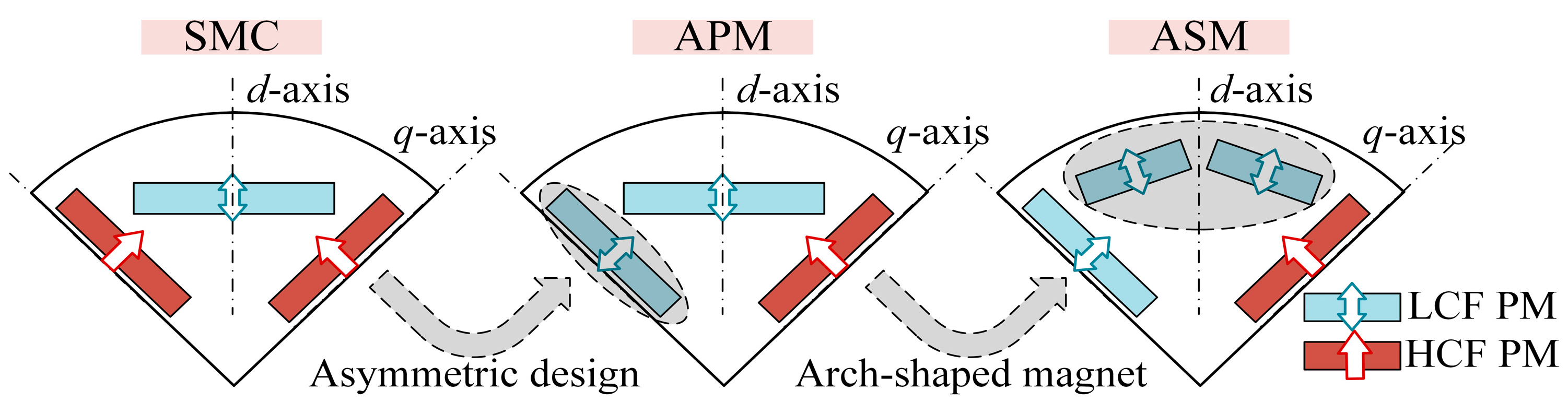
Figure 1 illustrates the topological evolution of the ASM-VFMM, which is derived from the conventional SMC structure. Within the conventional SMC layout, the magnetic fluxes of the first and second PM layers are connected in series, significantly reducing the magnetic flux short-circuiting effect at the weakened-flux state. To further enhance the MFA capability of the SMC configuration, an APM design is employed in the second layer to achieve the parallel magnetic circuit, thereby constructing an APM structure. Additionally, it should be noted that the MFA capability of the VFMM primarily stems from LCF PMs. To further increase the usage of LCF PMs, an arch-shaped magnet design for the first layer is introduced into the APM structure, ultimately forming the proposed ASM-VFMM.
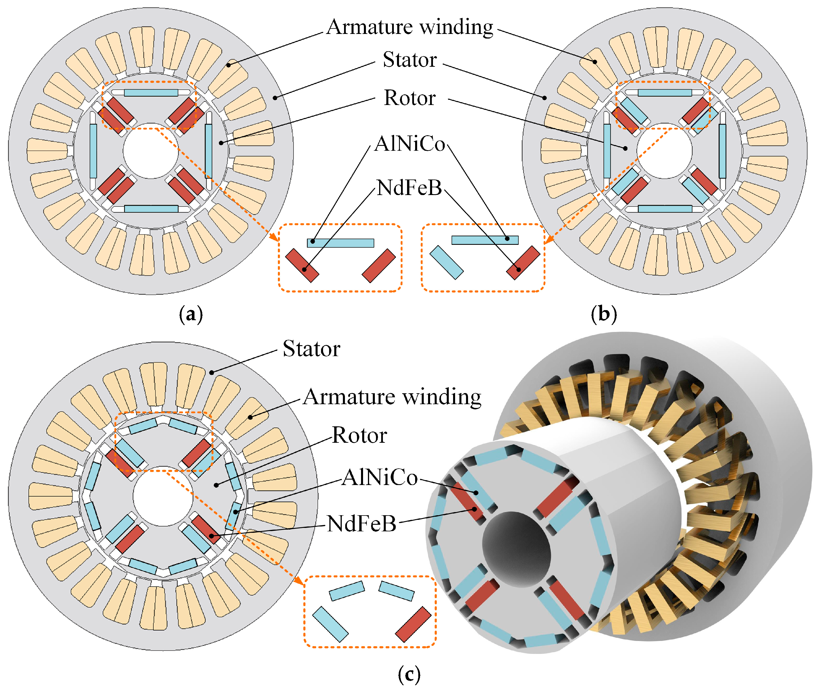
Furthermore, the structures of the three VFMMs are shown in Figure 2, all of which adopt a pole–slot combination of 21p/4s. In the proposed ASM-VFMM, the rotor features a dual-layer magnet layout configured into an arch-shaped geometry. For the layer nearer to the air gap, an inverted V-shaped magnet configuration is employed to facilitate magnetization. The second layer adopts a spoke-type arrangement with an asymmetric magnet layout, which allows a larger volume of LCF magnets to be utilized, thereby improving the MFA performance. Additionally, the HCF magnets positioned in the second layer form a series magnetic circuit together with nearby LCF magnets, which helps maintain magnetization stability under load conditions. The key design parameters for all three machine configurations are summarized in Table 1.

2.2. Theoretical Modeling

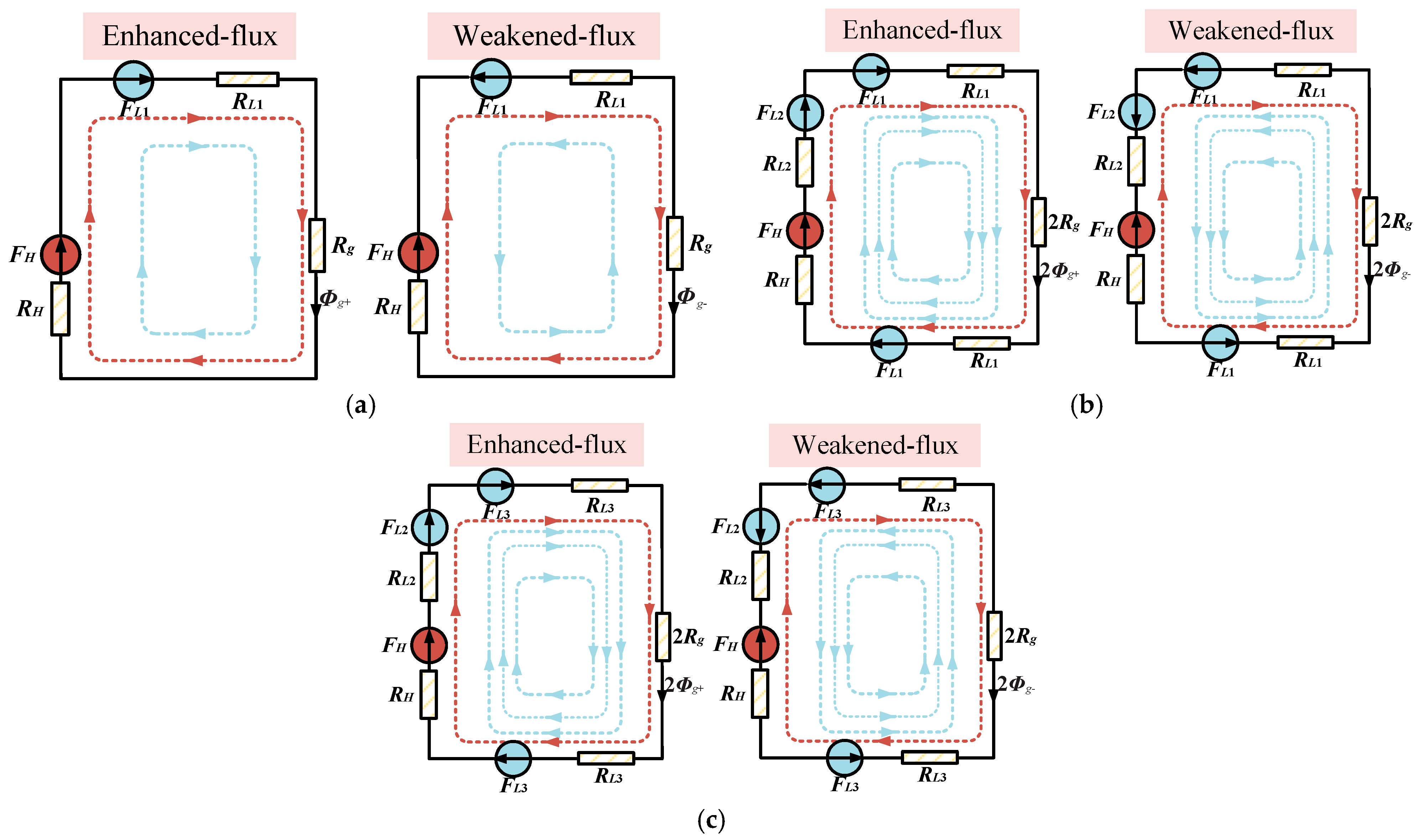
The MFA capability of the three machines is derived from the variable magnetization state characteristics of the LCF PMs. However, due to the different positions of the LCF PMs, the three machines exhibit different electromagnetic properties. To demonstrate the advantages of the proposed machine with respect to MFA capability, simplified equivalent magnetic circuit models are developed for the three machines, as depicted in Figure 3. In these models, the subscripts “g”, “Li”, and “H” denote the air-gap, LCF and HCF PMs positioned at different locations. The symbols “F” and “R” correspond to the magnetomotive forces and magnetic reluctances of the respective components.
The magnetic circuit model of the SMC structure is illustrated in Figure 3a. The VFMM operates in two distinct extreme states. Specifically, when the flux directions of the HCF and LCF magnets are aligned, the SMC configuration operates at the enhanced-flux state, and the corresponding air-gap flux can be expressed as
Φ g + = F H + F L 1 R L 1 + R g + R H
Conversely, when the flux directions of the two types of magnets oppose each other, the machine is at the weakened-flux state, and the air-gap flux can be formulated as
Φ g = F H F L 1 R L 1 + R g + R H
The ratio of the air-gap fluxes in these two states provides a measure of the MFA range, which is given by
k S M C = 1 + 2 F L 1 F H F L 1 = 1 + 2 F H / F L 1 1
Following a similar approach, the air-gap fluxes for the APM configuration at the enhanced-flux and weakened-flux states can be written, respectively, as
Φ g + = F H + 2 F L 1 + F L 2 2 R H + 2 R L 1 + R L 2 + R g
Φ g = F H - 2 F L 1 - F L 2 2 R H + 2 R L 1 + R L 2 + R g
The MFA range of the APM structure can therefore be expressed as
k A P M = 1 + 2 2 F L 1 + F L 2 F H - 2 F L 1 - F L 2 = 1 + 2 F H / 2 F L 1 + F L 2 1
Considering that the sum of 2FL1 and FL2 exceeds FL, it can be deduced from Equations (3) and (6) that the MFA range of APM is more extensive than that of SMC.
Likewise, the air-gap fluxes for the proposed ASM-VFMM in two states can be represented as
Φ g + = F H + 2 F L 3 + F L 2 2 R H + 2 R L 3 + R L 2 + R g
Φ g = F H - 2 F L 3 - F L 2 2 R H + 2 R L 3 + R L 2 + R g
Therefore, the MFA range of the ASM can be given by
k A S M = 1 + 2 2 F L 3 + F L 2 F H - 2 F L 3 - F L 2 = 1 + 2 F H / 2 F L 3 + F L 2 1
The arched PMs are employed in the first layer of the proposed ASM-VFMM, enabling the PMs of this layer to possess a greater MMF compared with the SMC and APM structures, i.e., FL3 is greater than FL1. Consequently, according to Equations (3), (6) and (9), kASM exceeds both kAPM and kSMC. This indicates that the proposed ASM design delivers the broadest MFA range among the three machines, with the APM structure ranking second and the SMC structure ranking third.

3. Electromagnetic Performance

Before the performance evaluation, the basic 2-D finite element analysis settings are established. The simulation considers the non-linear B-H curves of the iron cores while neglecting end effects. The iron losses are calculated using Bertotti’s model, with the coefficients obtained from the lamination manufacturer’s data. The armature copper losses are computed from the DC resistances of the windings at the assumed operating temperature. To execute the state switching, a straightforward single-pulse current control strategy is adopted and applied along the d-axis. Specifically, the control strategy utilizes a single current pulse with an amplitude of 15 A and a fixed pulse duration of 60 ms. A positive d-axis pulse is applied for remagnetization (enhanced-flux state), while a negative d-axis pulse is used for demagnetization (weakened-flux state).

3.1. Magnetization Performance

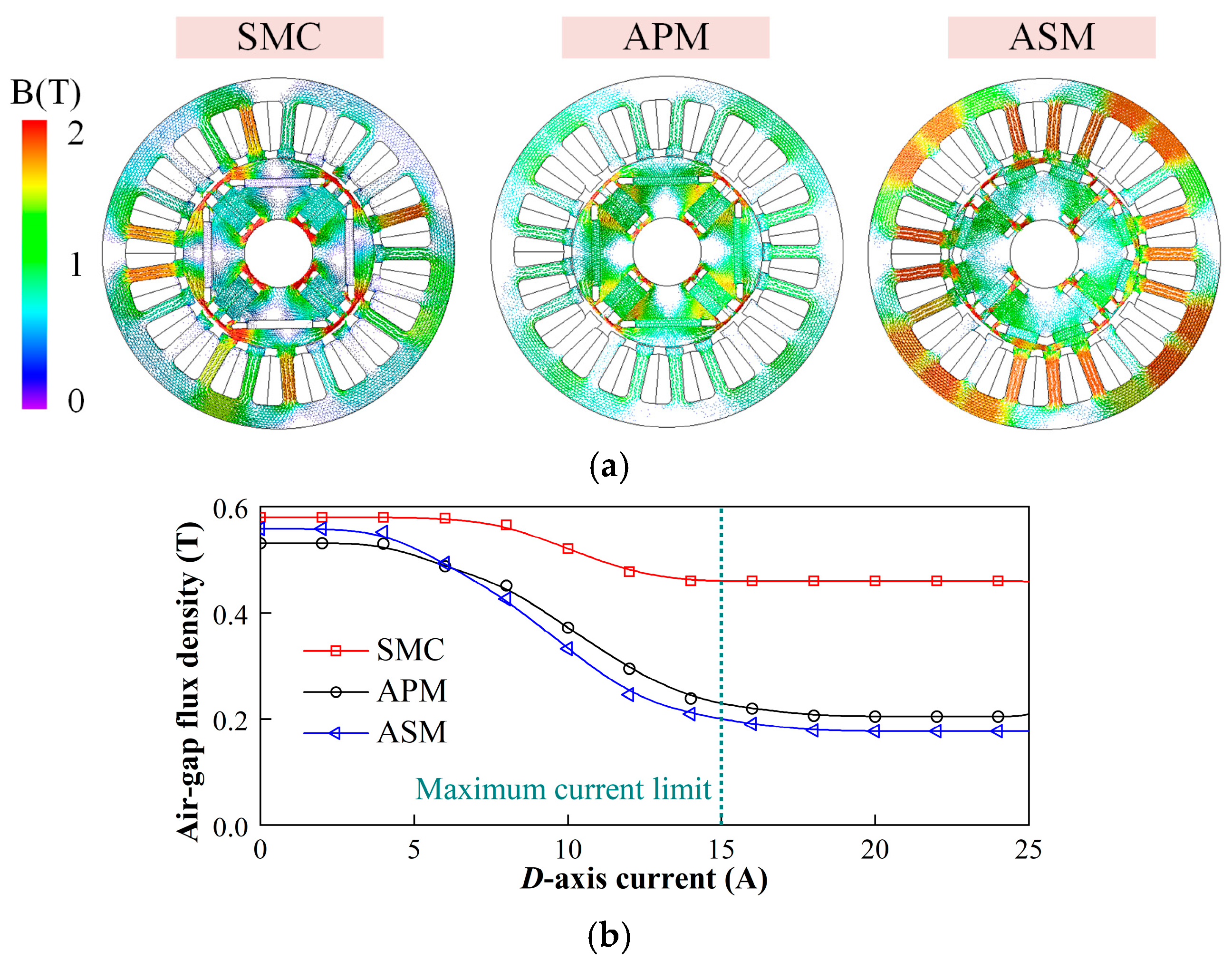
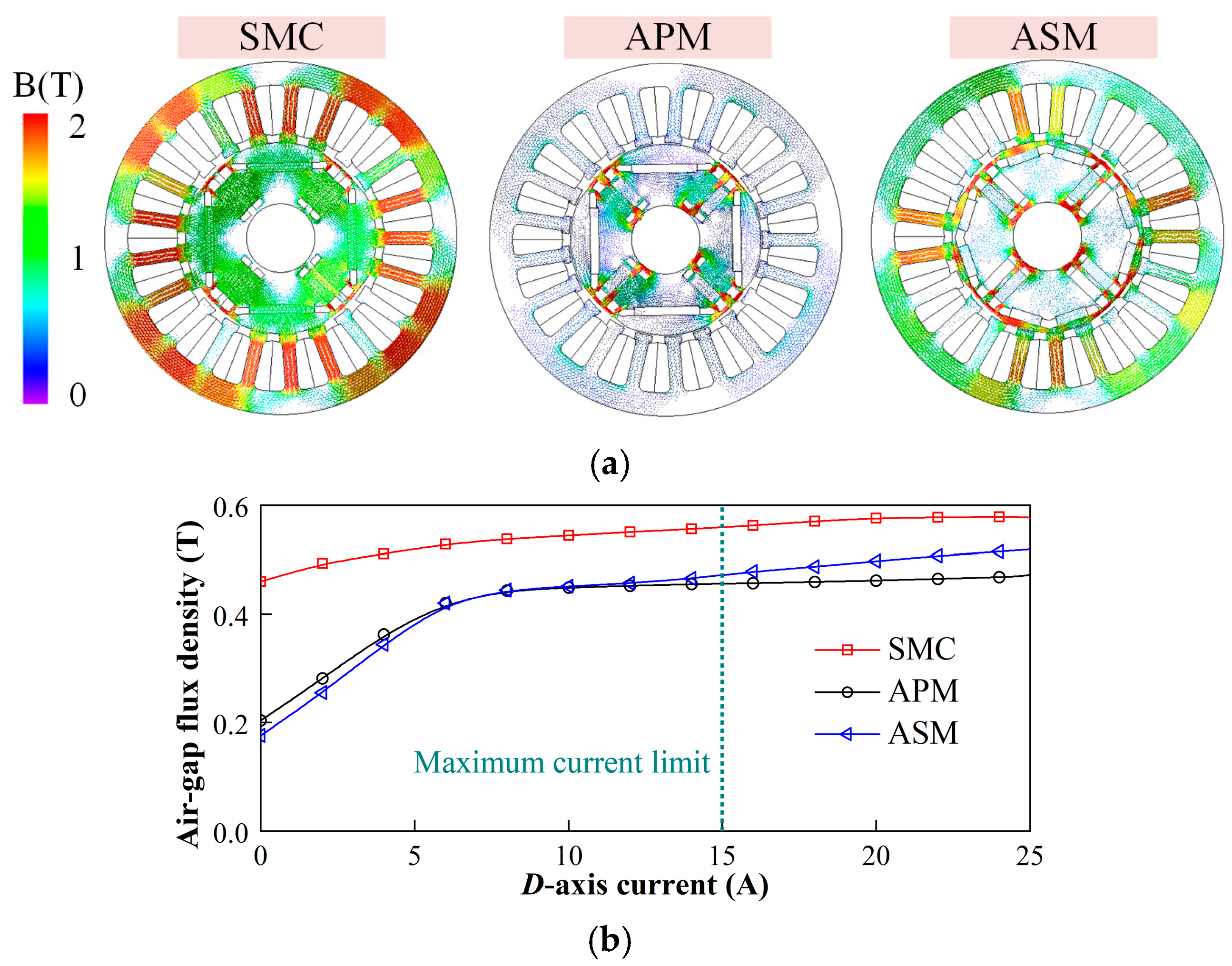
Figure 4 illustrates the demagnetization characteristics of three VFMMs. It is noteworthy that due to the constraint of inverter capacity, the upper limit for magnetization current in this paper is set at twice the peak current (15 A). After the demagnetization process, there is a reduction in the air-gap magnetic flux densities of the three VFMMs. Notably, the ASM-VFMM can achieve the lowest air-gap flux density. This can largely be attributed to its extensive usage of LCF PMs. In contrast, the SMC machine exhibits the worst demagnetization characteristics.
Additionally, Figure 5 illustrates the remagnetization characteristics of the three machines. Benefiting from the highest amount of HCF magnets, the SMC structure achieves the highest air-gap flux density with the smallest variation range. Moreover, under the maximum magnetizing current limit, the ASM structure exhibits superior remagnetization characteristics compared with the APM structure.

3.2. Open-Circuit Characteristics

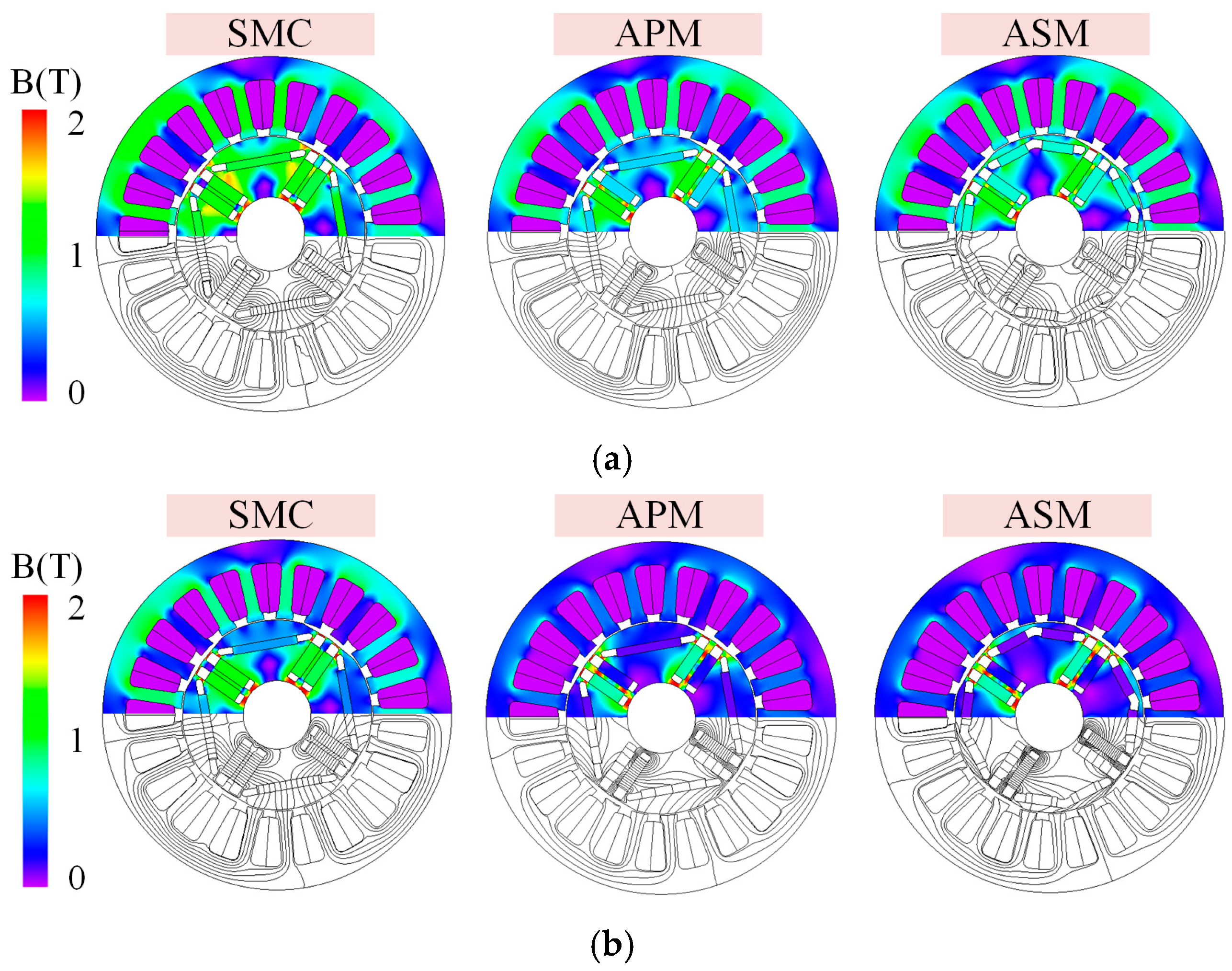
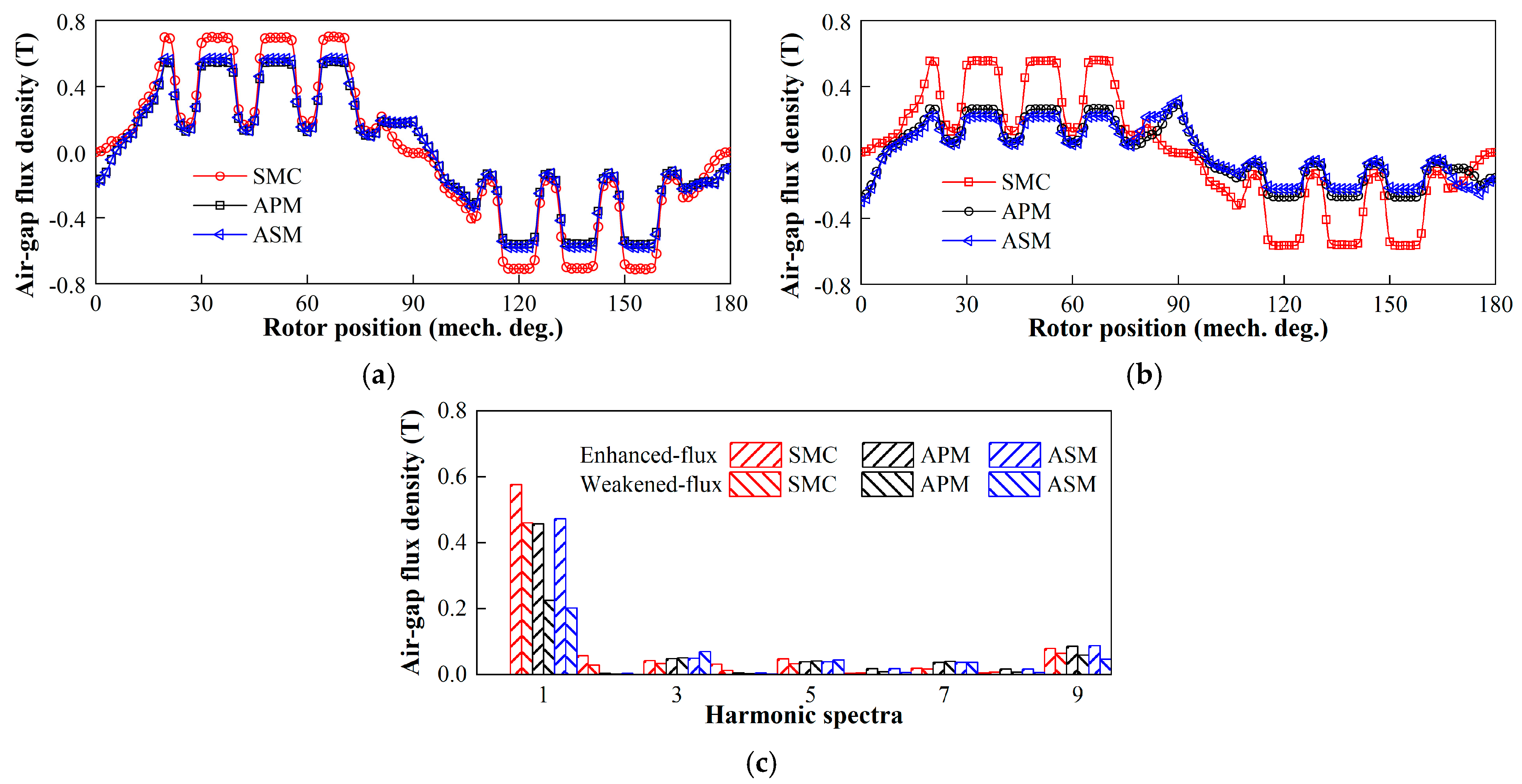
The open-circuit magnetic field distributions of the VFMMs are plotted in Figure 6. The proposed ASM-VFMM exhibits a substantial decrease in the magnetic field at the weakened-flux state compared with at the enhanced-flux state. However, due to the narrow MFA range, the SMC structure still demonstrates a high flux distribution on the rotor side at the weakened-flux state. Corresponding open-circuit air-gap flux densities are presented in Figure 7. Because of the large proportion of HCF magnets, the SMC design shows the highest air-gap flux density under both enhanced-flux and weakened-flux states, yet it also has the most limited MFA capability. Compared to the SMC structure, the APM structure exhibits an enhanced MFA range while its enhanced flux magnetic flux density is relatively low. On the other hand, compared to the APM structure, the proposed ASM configuration is capable of achieving the second-highest air-gap flux density due to the presence of arch-shaped PMs. Besides, the proposed machine can achieve over 2.36 times the MFA range through the magnetization operation, representing the maximum value among the three designs.

3.3. On-Load Performance

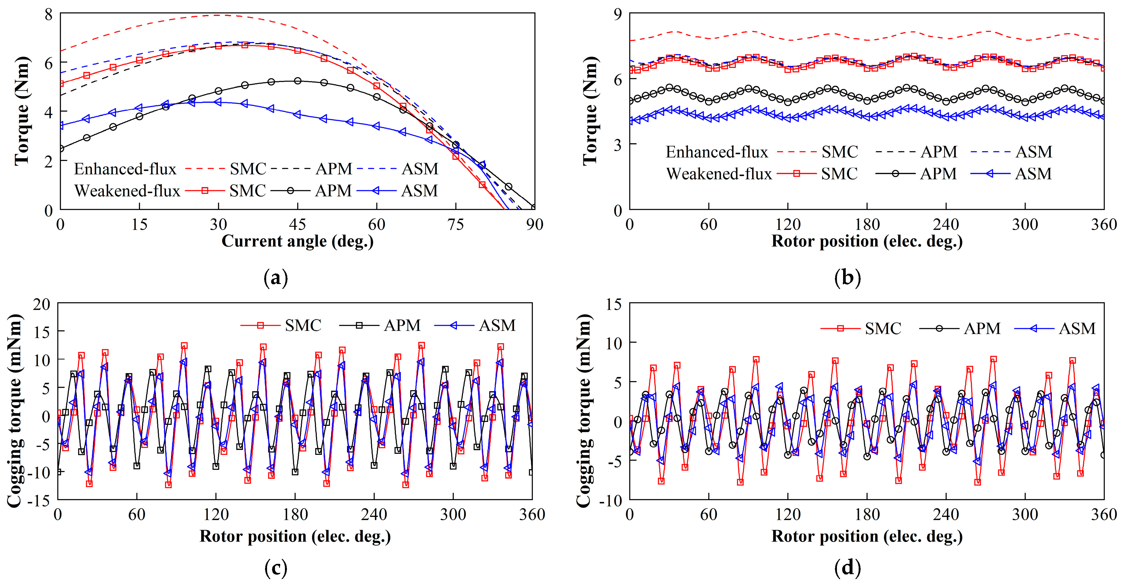
Figure 8 illustrates the torque characteristics of the machines at both enhanced-flux and weakened-flux states. Owing to the excessive presence of HCF PMs, the SMC structure has a maximum torque current angle of approximately 30° in both states, indicating a higher utilization of PM torque. Besides, the APM-VFMM exhibits significantly different torque current angles at various states, with a notably larger torque current angle at the weakened-flux state. Additionally, because the SMC structure exhibits the highest air-gap flux density, it demonstrates the strongest torque capability. Conversely, the broad MFA range of the ASM structure significantly reduces the contribution of weakened-flux PM torque, consequently leading to minimal torque at the weakened-flux state. Additionally, the torque ripples of the three machines are illustrated in Figure 8c,d. The torque ripple of the enhanced-flux state is slightly larger than that of the weakened-flux state, where the SMC structure demonstrates the highest torque ripple, while the remaining two structures are relatively close to each other in terms of torque ripple characteristics.
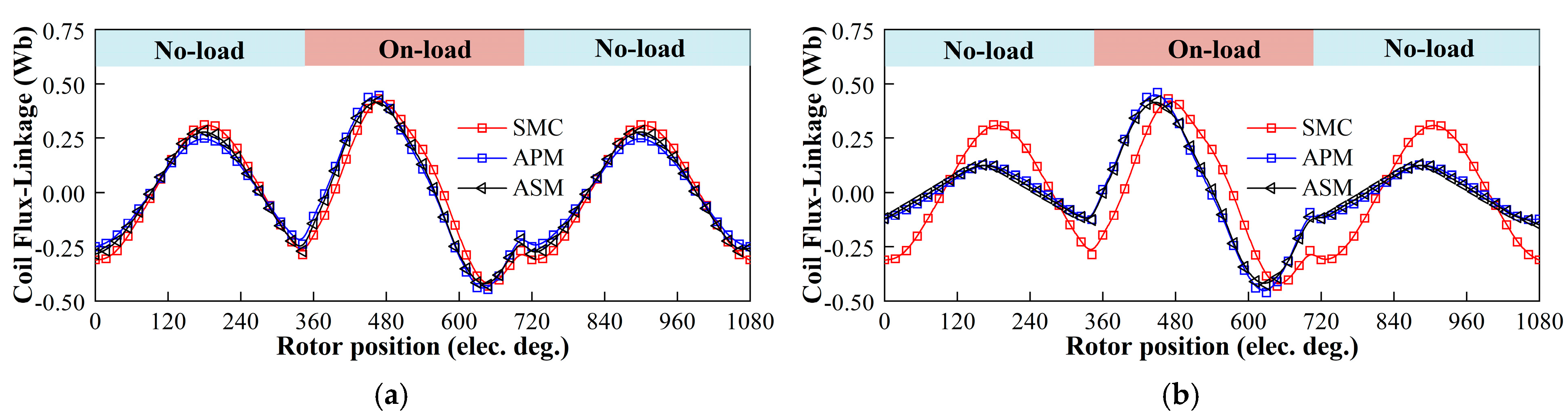
The on-load magnetization stabilization capabilities of these machines are shown in Figure 9. A machine is considered to possess stable magnetization stabilization capability under on-load if the coil flux linkage does not experience a reduction after load operation. The results show that all three machines are capable of maintaining stable flux linkage at two states, a finding which can be largely attributed to the presence of the series magnetic circuit.

3.4. Efficiency Maps

The efficiency maps are directly calculated from the flux linkages and iron losses following the approach presented in [24]. The armature copper losses are computed from the DC resistances, and the total loss is the sum of copper loss and iron loss. The efficiency is then obtained as the ratio of output mechanical power to input electrical power.
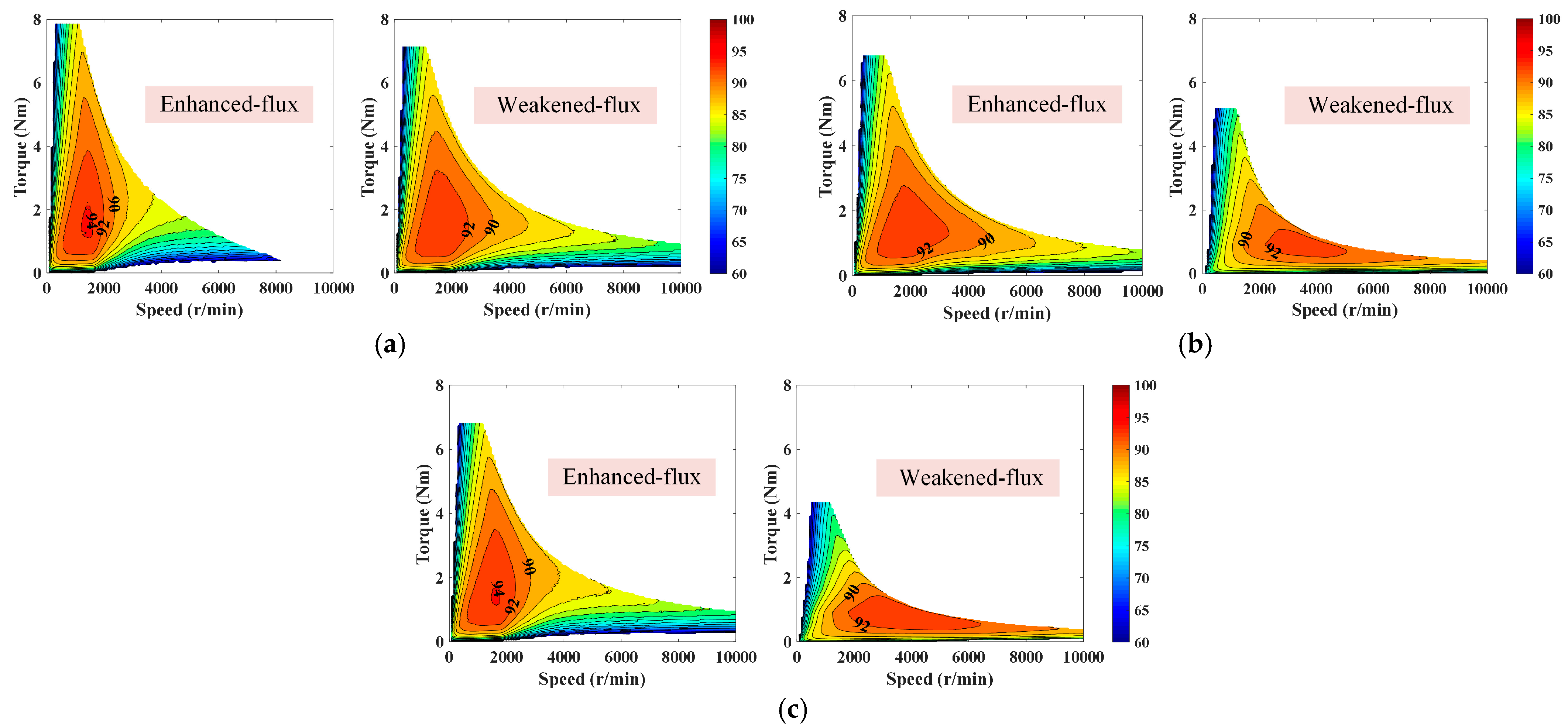
Figure 10 shows efficiency maps of these machines at different states. Under the enhanced-flux state, the high-efficiency region for all three machines is concentrated in the low-speed and low-to-medium torque area, whereas efficiency in the high-speed region remains relatively low. By transitioning from the enhanced-flux state to the weakened-flux state, the high-efficiency region can be relocated from low speeds to high speeds. However, the high-efficiency range (>90%) of the SMC structure is maintained within 3600 r/min, which is mainly due to its insufficient MFA capability. The APM and ASM structures can extend the high-efficiency range to 7900 r/min and 9200 r/min, respectively. This indicates that the proposed ASM-VFMM features the best overall high-efficiency characteristics among the three machines by the magnetization operation.
To provide a comprehensive and clear comparison, the main quantitative electromagnetic performance results for the SMC, APM, and ASM structures are summarized in Table 2.

4. Conclusions

In this paper, a novel ASM-VFMM is proposed with the aim of expanding MFA range and enhancing overall efficiency. The proposed ASM-VFMM adopts a dual-layer PM configuration, with both the first and second layers featuring arch-shaped magnet designs coupled with an APM arrangement. This design increases the amount of LCF magnets, thereby mitigating magnetic flux and expanding the MFA range. Theoretical modeling demonstrates that the proposed machine has a larger MFA range compared to other structures. Furthermore, comparative results show that the proposed ASM design offers superior magnetization characteristics, the broadest MFA range, and favorable load magnetization stability among three machines. Most importantly, the SMC and APM configurations maintain high-efficiency ranges of 3600 r/min and 7900 r/min, respectively, while the ASM configuration extends the high-efficiency range to 9200 r/min. This also means that the proposed ASM-VFMM can provide favorable high-efficiency characteristics overall, especially in the high-speed region. Future work will focus on prototyping the proposed ASM-VFMM and carrying out experimental tests to validate the findings reported in this paper

Author Contributions

W.L.: Writing—original draft, Software, Data curation, Conceptualization. S.Q.: Validation, Software. J.C.: Resources, Investigation, Conceptualization. P.L.: Visualization, Validation. X.S.: Visualization, Validation. R.L.: Validation. C.Z.: Supervision, Project administration, Funding acquisition. All authors have read and agreed to the published version of the manuscript.

Funding

This research was funded in part by the National Natural Science Foundation of China (52307074 and U23A20645), in part by the Zhejiang Provincial Natural Science Foundation of China (LQ24E070002), in part by the Ningbo Youth Science and Technology Innovation Leading Talent Project (2025QL062), and in part by the Ningbo Science and Technology Innovation 2025 Major Special Project (2023Z007).

Data Availability Statement

The original contributions presented in the study are included in the article, further inquiries can be directed to the corresponding author.

Conflicts of Interest

The authors declare no conflicts of interest.

References

  1. Deepak, K.; Frikha, M.A.; Benômar, Y.; El Baghdadi, M.; Hegazy, O. In-Wheel Motor Drive Systems for Electric Vehicles: State of the Art, Challenges, and Future Trends. Energies 2023, 16, 3121. [Google Scholar] [CrossRef]
  2. Mörée, G.; Sjölund, J.; Leijon, M. A Review of Permanent Magnet Models Used for Designing Electrical Machines. IEEE Trans. Magn. 2022, 58, 1–19. [Google Scholar] [CrossRef]
  3. Cai, S.; Kirtley, J.L.; Lee, C.H.T. Critical Review of Direct-Drive Electrical Machine Systems for Electric and Hybrid Electric Vehicles. IEEE Trans. Energy Convers. 2022, 37, 2657–2668. [Google Scholar] [CrossRef]
  4. Luk, P.C.K.; Abdulrahem, H.A.; Xia, B. Low-Cost High-Performance Ferrite Permanent Magnet Machines in EV Applications: A Comprehensive Review. eTransportation 2020, 6, 100080. [Google Scholar] [CrossRef]
  5. Ostovic, V. Memory Motors. IEEE Ind. Appl. Mag. 2003, 9, 52–61. [Google Scholar] [CrossRef]
  6. Ge, M.; Li, J.; Qu, R.; Lu, Y.; Chen, J. A Synthetic Frozen Permeability Method for Torque Separation in Hybrid PM Variable-Flux Machines. IEEE Trans. Appl. Supercond. 2018, 28, 1–5. [Google Scholar] [CrossRef]
  7. Ibrahim, M.; Masisi, L.; Pillay, P. Design of Variable Flux Permanent-Magnet Machine for Reduced Inverter Rating. IEEE Trans. Ind. Appl. 2015, 51, 3666–3674. [Google Scholar] [CrossRef]
  8. Tu, R.; Yang, H.; Lin, H.; Zhan, H.; Wu, D.; Yu, M.; Chen, L.; Chen, W. Investigation of a Novel Consequent-Pole Flux-Intensifying Memory Machine. Energies 2022, 15, 5501. [Google Scholar] [CrossRef]
  9. Abdel-Mageed, B.S.; Blanchard St-Jacques, B.; Shi, R.; Pillay, P. Modifying the Properties of Low Coercive Field Magnets for Improved Performance of Variable Flux Motors. In Proceedings of the 2024 IEEE Energy Conversion Congress and Exposition (ECCE); IEEE: Piscataway, NJ, USA, 2024; pp. 5880–5885. [Google Scholar]
  10. Gagas, B.S.; Sasaki, K.; Athavale, A.; Kato, T.; Lorenz, R.D. Magnet Temperature Effects on the Useful Properties of Variable Flux PM Synchronous Machines and a Mitigating Method for Magnetization Changes. IEEE Trans. Ind. Appl. 2017, 53, 2189–2199. [Google Scholar] [CrossRef]
  11. Zeng, X.; Lin, H.; Zhong, Y.; Zhao, X.; Yang, H.; Liu, X. Design Concept and Performance Analysis of Dual-Variable Flux Memory Machines for Traction Drive. IEEE Trans. Transp. Electrif. 2025, 11, 2171–2180. [Google Scholar] [CrossRef]
  12. Liu, D.; Yang, H.; Wang, C.; Wang, C.; Liu, X.; Yu, L.; Lin, H.; Zhang, Z.; Chen, L.; Yang, L. Inverter-Rating-Reduction Design Methodology of Hybrid-Variable-Flux PM Machine Considering Re- and Demagnetizing Current Balance. IEEE Trans. Ind. Electron. 2026, 1–13. [Google Scholar] [CrossRef]
  13. Tsunata, R.; Yokomichi, K.; Takemoto, M.; Imai, J. Design and Analysis of Hybrid-Excitation Variable Flux Memory Motor for Traction Applications: Improving Output Power in High-Speed Area During Six-Step Operation Mode. IEEE Access 2023, 11, 82024–82036. [Google Scholar] [CrossRef]
  14. Liu, W.; Zhang, C.; Shu, X.; Fu, Y.; Chen, J. Magnetic Circuit Number Improvement of Novel Multiseries Magnetic Circuit Variable Flux Memory Machines with Reduced Magnetizing Current. IEEE Trans. Transp. Electrif. 2025, 11, 3838–3847. [Google Scholar] [CrossRef]
  15. Arribas, B.; Almandoz, G.; Egea, A.; Madina, P.; Iturbe, I. Adoption of Multiphase and Variable Flux Motors in Automotive Applications. Appl. Sci. 2024, 14, 10932. [Google Scholar] [CrossRef]
  16. Liu, W.; Chen, J.; Zhang, C.; Qiu, S.; Li, Y.; Yang, H. A Novel Variable Flux Memory Machine with Magnetic Circuit Complementary Structure. IEEE/ASME Trans. Mechatron. 2026, 31, 1010–1021. [Google Scholar] [CrossRef]
  17. Hu, Y.; Chen, B.; Xiao, Y.; Li, X.; Zhang, Z.; Shi, J.; Li, L. Research and Design on Reducing the Difficulty of Magnetization of a Hybrid Permanent Magnet Memory Motor. IEEE Trans. Energy Convers. 2020, 35, 1421–1431. [Google Scholar] [CrossRef]
  18. Wang, M.; Li, W.; Zhang, S.; Liu, Y.; Zheng, P.; Liu, F. Design and Operation Performance Analysis of a Novel Three-Segment V-Shape Series–Parallel Variable-Flux Machine. IEEE Trans. Ind. Electron. 2025, 72, 1303–1313. [Google Scholar] [CrossRef]
  19. Liu, W.; Yang, H.; Lin, H.; Zhang, C.; Chen, J.; Qiu, S.; Li, R.; Shu, X.; Li, Y. Design Method of Hybrid Magnet Arrangement in Variable Flux Memory Machines Based on Elementary-Unit-Combined Concept. IEEE Trans. Energy Convers. 2024, 39, 700–710. [Google Scholar] [CrossRef]
  20. Athavale, A.; Reigosa, D.; Akatsu, K.; Sakai, K.; Lorenz, R.D. Scalability and Key Tradeoffs of Variable Flux PM Machines for EV Traction Motor Systems. In Proceedings of the 2018 IEEE Energy Conversion Congress and Exposition (ECCE), Portland, OR, 2018; IEEE: Piscataway, NJ, USA, 2018; pp. 2292–2299. [Google Scholar]
  21. Zhang, S.; Wang, F.; Zhu, J.; Zheng, P.; Liu, G. Multi-objective hierarchical optimisation design and experimental verification of an alterable-magnetic-circuit variable-flux memory machine. IET Electr. Power Appl. 2024, 18, 790–800. [Google Scholar] [CrossRef]
  22. Kesten, J.; Müller, P.; Brodatzki, M.; Doppelbauer, M. Holistic Efficiency Map Calculation of Variable Flux Machines Regarding Relative Magnetisation. In Proceedings of the 2024 International Symposium on Power Electronics, Electrical Drives, Automation and Motion (SPEEDAM); IEEE: Piscataway, NJ, USA, 2024; pp. 1023–1029. [Google Scholar]
  23. Maekawa, S.; Yuki, K.; Matsushita, M.; Nitta, I.; Hasegawa, Y.; Shiga, T.; Hosoito, T.; Nagai, K.; Kubota, H. Study of the Magnetization Method Suitable for Fractional-Slot Concentrated-Winding Variable Magnetomotive-Force Memory Motor. IEEE Trans. Power Electron. 2014, 29, 4877–4887. [Google Scholar] [CrossRef]
  24. Chu, W.Q.; Zhu, Z.Q.; Zhang, J.; Liu, X.; Stone, D.A.; Foster, M.P. Investigation on Operational Envelops and Efficiency Maps of Electrically Excited Machines for Electrical Vehicle Applications. IEEE Trans. Magn. 2015, 51, 1–10. [Google Scholar] [CrossRef]
Figure 1. Topological evolution of the proposed ASM-VFMM.
Energies 19 02199 g001
Figure 2. Configuration of the VFMMs. (a) SMC. (b) APM. (c) ASM.
Energies 19 02199 g002
Figure 3. Magnetic circuit models. (a) SMC. (b) APM. (c) ASM.
Energies 19 02199 g003
Figure 4. Demagnetization characteristics. (a) Demagnetization vector distributions at 15A. (b) Different demagnetization currents.
Energies 19 02199 g004
Figure 5. Remagnetization characteristics. (a) Remagnetization vector distributions at 15A. (b) Different remagnetization currents.
Energies 19 02199 g005
Figure 6. Open-circuit magnetic fields. (a) Enhanced flux. (b) Weakened flux.
Energies 19 02199 g006
Figure 7. Open-circuit air-gap flux densities. (a) Waveforms at enhanced-flux state. (b) Waveforms at weakened-flux state. (c) Harmonic spectra.
Energies 19 02199 g007
Figure 8. Torque performance. (a) Torque-angle waveforms. (b) Steady-state torque waveforms. (c) Cogging torque at enhanced-flux state. (d) Cogging torque at weakened-flux state.
Energies 19 02199 g008
Figure 9. On-load magnetization stabilization capability. (a) Enhanced flux. (b) Weakened flux.
Energies 19 02199 g009
Figure 10. Efficiency maps. (a) SMC. (b) APM. (c) ASM.
Energies 19 02199 g010
Table 1. Key design parameters of the three machines.
ItemsSMCAPMASM
Stator slot21
Rotor pole4
Stator outer diameter (mm)122
Stack length (mm)55
Air gap length (mm)0.35
HCF PM usage (mm2)418.97 209.49209.49
LCF PM usage (mm2)276.20485.68516.34
Peak current (A)7.5
Rated speed (r/min)1500
Magnetization current (A)15
LCF PM material gradeAlNiCo 9
HCF PM material gradeN38SH
Iron core material35CS440
Table 2. Quantitative performance comparison of the three machines.
Performance MetricsSMCAPMASM
Air-gap flux density (enhanced flux, T)0.580.450.47
Air-gap flux density (weakened flux, T)0.460.230.20
MFA range (ratio)1.261.962.36
Average torque (enhanced flux, Nm)7.936.776.81
Average torque (weakened flux, Nm)6.715.254.40
Torque ripple (enhanced flux, %)5.567.548.61
Torque ripple (weakened flux, %)9.5512.6913.12
On-load magnetization stabilityStableStableStable
Speed range with efficiency > 90% (r/min)Up to 3600Up to 7900Up to 9200
Disclaimer/Publisher’s Note: The statements, opinions and data contained in all publications are solely those of the individual author(s) and contributor(s) and not of MDPI and/or the editor(s). MDPI and/or the editor(s) disclaim responsibility for any injury to people or property resulting from any ideas, methods, instructions or products referred to in the content.