Article

Enhancing Oil Recovery and CO2 Sequestration Efficiency in Ultra-Deep Heterogeneous Waxy Reservoirs: A Comparative Experimental Study

1
Exploration and Development Research Institute, PetroChina Huabei Oilfield Company, Renqiu 062550, China
2
School of Petroleum Engineering, Southwest Petroleum University, Chengdu 610500, China
3
Petroleum Recovery Research Center, New Mexico Institute of Mining and Technology, Socorro, NM 87801, USA
*
Authors to whom correspondence should be addressed.
Energies 2026, 19(7), 1777; https://doi.org/10.3390/en19071777
Submission received: 4 March 2026 / Revised: 28 March 2026 / Accepted: 31 March 2026 / Published: 4 April 2026

Abstract

Ultra-deep high-pour-point oil (waxy crude oil) reservoirs under high-temperature and high-pressure conditions are characterized by severe heterogeneity and poor displacement efficiency, with the crude oil exhibiting a pour point of approximately 47 °C. Using the XH block as a representative ultra-deep reservoir, this study systematically examines the displacement mechanisms of CO2 flooding and CO2–water-alternating-gas (WAG) flooding. This study aims to elucidate the CO2–oil interactions between CO2 and waxy crude oil, to compare oil recovery and CO2 retention under different injection modes in media with varying permeability and heterogeneity, and to provide experimental support for field-scale development. Slim tube, swelling, and long-core flooding experiments were conducted under reservoir conditions (139 °C, 57 MPa). The phase behavior between CO2 and crude oil, as well as its impact on oil volume and flow properties, was analyzed. Moreover, continuous CO2 flooding and WAG flooding were compared in low-permeability and medium–high-permeability cores, and WAG was subsequently applied to a parallel-core system to quantify the effect of interlayer heterogeneity. Results indicate that while CO2 achieves miscibility with the waxy crude at reservoir pressure, its contribution to swelling and viscosity reduction is moderate compared to light oils; thus, recovery relies primarily on miscible displacement. Compared with continuous CO2 flooding, WAG effectively delays gas breakthrough and enlarges the swept volume, leading to higher oil recovery and CO2 storage efficiency. Increasing permeability reduces flow resistance and significantly enhances the oil recovery factor. In strongly heterogeneous systems, dominant flow through high-permeability channels markedly weakens displacement in low-permeability zones, resulting in lower overall recovery and CO2 retention. These results indicate that properly designed WAG schemes can improve the development performance of heterogeneous waxy oil reservoirs while simultaneously meeting CO2 storage requirements.

1. Introduction

Heterogeneity between high- and low-permeability layers is a critical factor controlling the efficiency of CO2 flooding [1,2]. Numerous displacement experiments indicate that CO2 tends to break through prematurely in high-permeability channels, while substantial volumes of residual oil remain trapped in low-permeability zones, significantly reducing overall sweep efficiency [3,4]. As the permeability contrast increases, the formation of viscous fingering and preferential flow paths is exacerbated, rendering continuous CO2 injection alone insufficient for effective recovery in low-permeability intervals [5]. Therefore, mobility control strategies, such as CO2–WAG and short-slug WAG, can effectively suppress preferential flow through high-permeability pathways, enhance the volumetric sweep in heterogeneous media, and improve recovery in medium- to low-permeability layers [6,7]. Experimental studies have shown that these approaches can typically increase oil recovery by an additional 8–25% compared to CO2 injection alone [8,9].
In heterogeneous reservoirs, the recovery of heavy, waxy crude oil is generally more challenging [10,11,12]. Existing PVT and swelling experiments indicate that under high-pressure or supercritical conditions, substantial CO2 dissolution can induce pronounced oil expansion and significantly reduce viscosity, thereby enhancing crude oil mobility and improving displacement efficiency [13]. However, current minimum miscibility pressure (MMP) test studies show that due to the high wax and heavy-component content, waxy crude oils typically exhibit elevated minimum miscibility pressures with CO2, making complete miscibility difficult to achieve under actual reservoir pressures [14,15].
At the experimental scale, long-core flooding tests have been widely employed to evaluate recovery performance in heterogeneous reservoirs [16,17,18]. These experiments can more realistically capture flow pathways in heterogeneous media and reveal key mechanisms such as CO2-induced oil swelling and viscosity reduction. Their scale offers significant advantages over short-core tests [19,20]. In heterogeneous layers, researchers often arrange two or more long cores with different permeabilities in parallel to simulate the simultaneous injection into various reservoir layers under realistic conditions [21,22]. Furthermore, to assess the geological storage potential of CO2, sequestration and sequestration efficiency can be quantified using long-core flooding experiments, based on mass balance between injection and production [23,24]. As shown in Table 1, existing long-core experiments are typically conducted under relatively low temperature and pressure. In contrast, the reservoir conditions for waxy oil in heterogeneous layers in this study involve higher temperature and pressure, which more readily allow miscibility, necessitating displacement experiments under such conditions.
The XH block is characterized by ultra-deep, high-temperature, and high-pressure reservoir conditions. CO2 flooding in this area must account for the high pour point of the crude oil and the strong reservoir heterogeneity. From the XH-1 to XH-11 direction, both porosity and permeability generally decrease. In the XH-1 sand formation, the main porosity range is 16–22%, whereas in the XH-11 sand formation, it is 14–18%. The average permeability in the XH-1 sand formation predominantly ranges from 100 to 200 mD, while in the XH-11 sand formation it is mostly below 50 mD, with local zones between 50 and 100 mD.
Overall, existing studies exhibit several limitations. First, MMP tests and swelling tests still involve uncertainties when applied to complex waxy oil systems. Second, few long-core experiments have been conducted on waxy crude oils, and the existing tests are generally performed under relatively low temperature and pressure, limiting their relevance for high-temperature, high-pressure reservoirs. Third, in heterogeneous reservoirs with high- and low-permeability layers, the performance of WAG under different permeability conditions remains insufficiently understood.
To address these gaps, the present study introduces several improvements targeting the XH block reservoirs. The contributions of CO2 to oil swelling and viscosity reduction in waxy crude oil are quantitatively evaluated. High-temperature, high-pressure (139 °C, 57 MPa) long-core experiments are conducted to more realistically simulate deep reservoir conditions. Continuous CO2 injection is compared with WAG to analyze the impact of displacement strategy on recovery. Cores with different permeabilities are compared to examine CO2 flooding behavior in heterogeneous media. Parallel-core experiments are also performed to study the effect of reservoir heterogeneity, with comparisons made to single long-core tests. This study enhances the understanding of CO2 flooding mechanisms and provides practical guidance for CO2 EOR in the XH block.
The novelty of this study lies in addressing the limited understanding of CO2 flooding and WAG mechanisms in waxy crude oil reservoirs. Under high-temperature and high-pressure conditions, we systematically examine the displacement behavior of WAG flooding in complex heterogeneous systems and quantitatively evaluate the effects of different displacement methods on CO2 sequestration efficiency. These results provide new theoretical insights and experimental support for optimizing development strategies in waxy oil reservoirs.

2. Experimental Section

2.1. Experimental Materials

2.1.1. Gas Samples

The associated gas used in the experiment was blended from Anyue dry gas and CO2. Gas chromatography analysis showed that the composition of the blended associated gas was essentially consistent with the target associated gas. The data are shown in Table 2. The injected CO2 was commercial-grade gas.

2.1.2. Fluid Sample

Water Sample
The experimental water consisted of formation water and injection water prepared according to oilfield data. The parameters of the formation water are shown in Table 3.
Oil Sample
The dead oil from well XH 11-5-C1 was collected, and the pour point of the oil is 47 °C. The crude oil has a wax content of 25.6%, a wax appearance temperature of approximately 62 °C, a resin content of 6.7%, and an asphaltene content of 18.7%. Using an NDJ-9S digital viscometer, the viscosity of the dead oil was measured as 35.66 mPa·s (60 °C, 0.1 MPa), and its density was determined to be 0.8807 g/cm3 (20 °C, 0.1 MPa) using a pycnometer. The component composition was calculated based on the chromatographic analysis of the dead oil, with the results shown in Table 4. Analysis of the available dead oil indicates that its composition is generally consistent with the fluid report.
Using the field dead crude oil and the recombined associated gas, formation crude oil was recombined at a formation temperature of 139 °C and formation pressure of 57 MPa with a gas–oil ratio of 10.4 m3/m3. The recombination results are shown in Table 5.
Table 5 shows the recombined formation crude oil results. The errors in gas–oil ratio, saturation pressure, single-flash dead oil density, single-flash formation oil viscosity, formation volume factor at saturation pressure, formation oil density, and formation oil viscosity were all less than 5%, satisfying the experimental requirements.
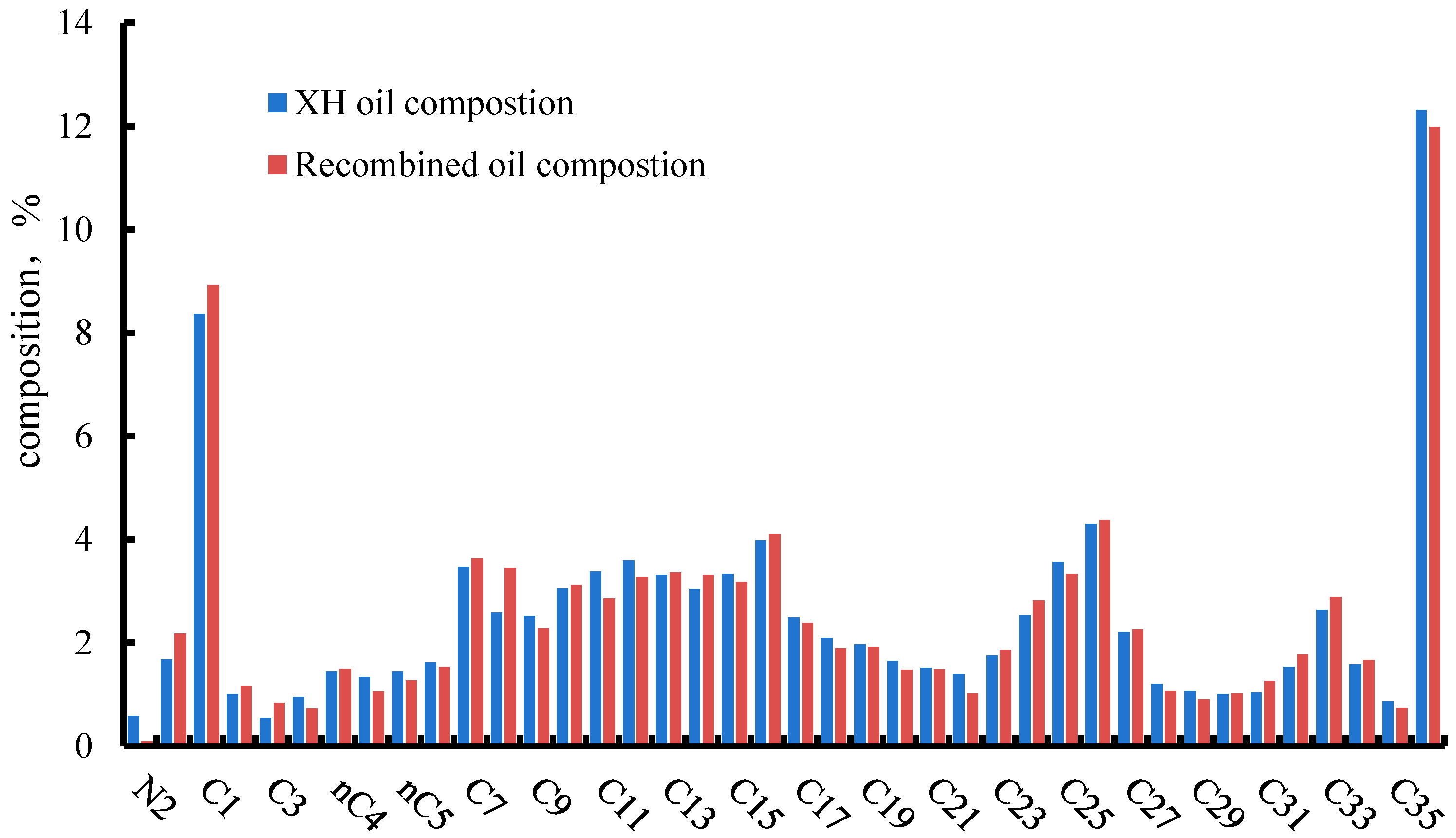
The recombined formation crude oil was analyzed using an oil-phase chromatograph. Its composition was compared with the flowing fluid composition from well XH 11-5-C1, as shown in Figure 1. The component composition of the recombined crude oil was consistent with formation fluid test data. Table 6 compares the composition of the target wellstream fluid and the actual recombined wellstream fluid, showing good agreement.

2.1.3. Rock Sample

The rock samples were core plugs from the XH block at depths of 5331.69 m to 5367.71 m. Based on porosity and permeability data measured after core cleaning, long-core samples were selected. The total length of the medium- to high-permeability long-core assembly was 96.15 cm, and the total length of the low-permeability long-core assembly was 97.9 cm. Both were standard 1-inch diameter long-core assemblies. Core parameters are given in Table 7 and Table 8.

2.2. Experimental Equipment and Methods

2.2.1. Slim Tube Experiment

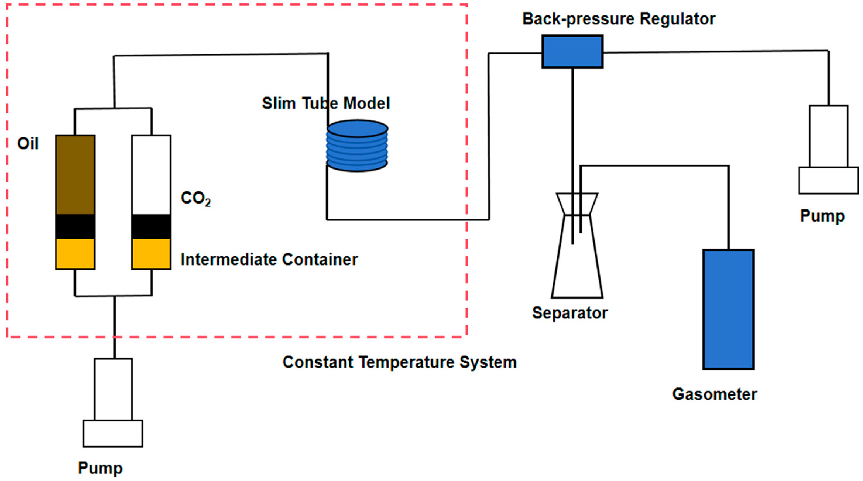
The slim tube experimental setup is shown in Figure 2. Tube parameters are shown in Table 9.
The procedures were as follows:
(1)
The slim tubes were cleaned with petroleum ether and dried.
(2)
Nitrogen was used to pressurize the tube to the target pressure at 139 °C.
(3)
The tube was saturated with the target oil sample. Injection was stopped once the outlet gas–oil ratio stabilized at 10.4 m3/m3.
(4)
CO2 was injected at 0.125 mL/min. The pressure drop along the slim tube was kept below 0.5 MPa. Pressure, oil volume, and gas volume were recorded every 0.1 PV.
(5)
After flooding was completed, the tube was cleaned and the procedure was repeated for the next experiment [30].

2.2.2. Swelling Test Experiment

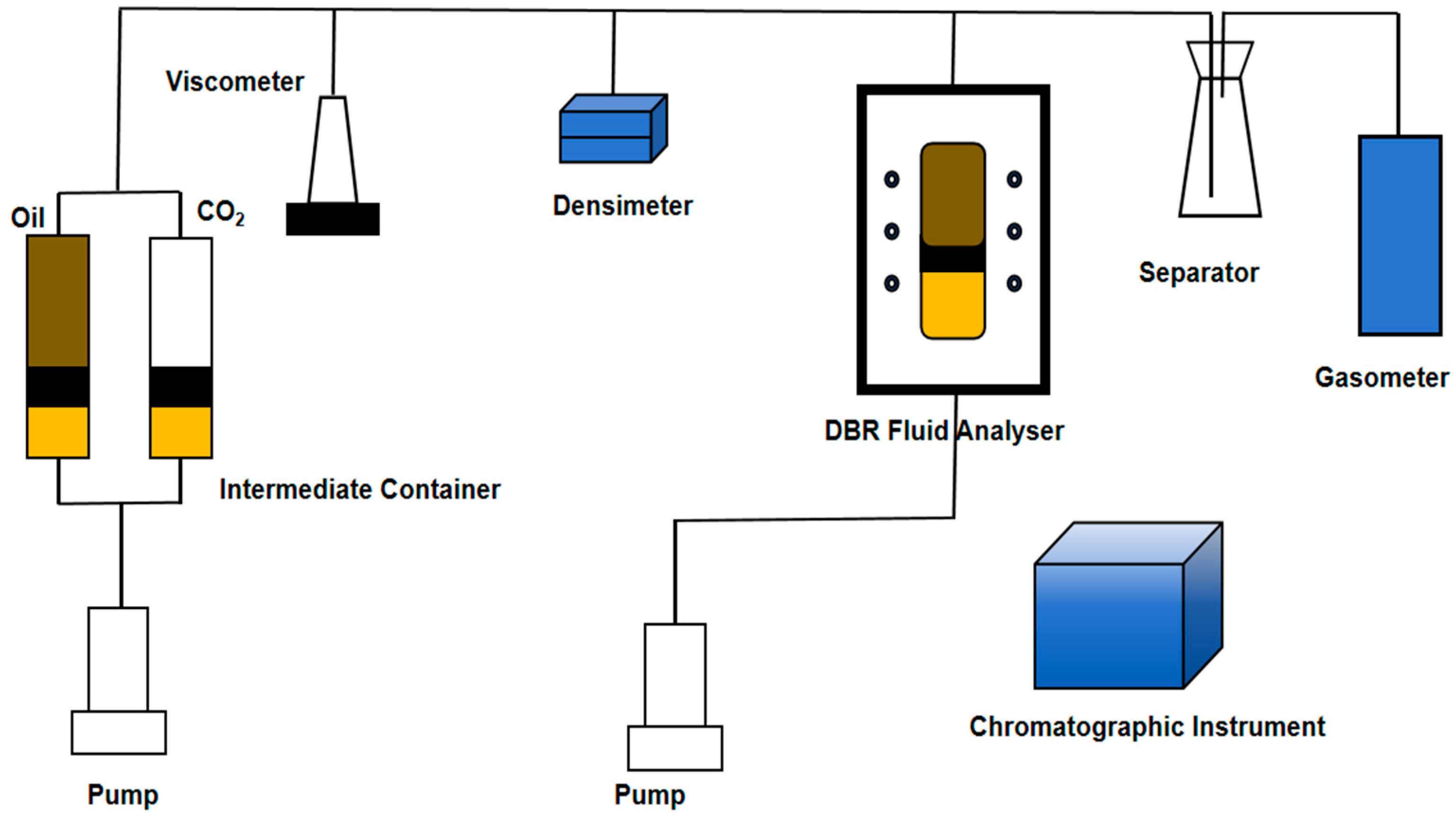
Fluid phase behavior experiments were conducted using a JEFRI mercury-free high-temperature and high-pressure PVT analyzer (DBR, Hamilton, ON, Canada). The system includes an injection pump, PVT cell, flash separator, densimeter, temperature control system, gas chromatograph, electronic balance, and gas booster pump (Figure 3).
The procedures were as follows:
(1)
A suitable amount of recombined formation fluid was transferred into the PVT cell and stabilized at 139 °C for 2 h.
(2)
Pressurized CO2 was injected into the formation oil sample in the PVT cell. The sample was stirred for 2 h to achieve a homogeneous single-phase state.
(3)
The pressure of the PVT cell was gradually decreased, and the pressure–volume data were continuously recorded. The bubble-point pressure of the swollen mixture was identified as the pressure at which minute gas bubbles were first observed visually in the PVT cell.
(4)
A small amount of fluid sample was subjected to flash separation at standard conditions (p = 0.101 MPa and T = 20 °C). The flashed data and the volume of oil in the PVT cell were used to calculate the formation volume factor (FVF), density, and gas–oil ratio at the bubble-point pressure.
(5)
At the bubble-point pressure, predetermined molar fractions of CO2 were introduced into the PVT cell. The pressure was then increased to the target high value, and the system was stirred for 24 h to achieve complete CO2 dissolution in the oil.
(6)
The swelling factor (SF) can be obtained by taking the ratio of the volume of oil in the PVT cell after each CO2 injection to the original oil volume (both at the bubble-point pressure).
(7)
Experimental steps (2) to (7) were repeated for different CO2 injection molar percentages [30].

2.2.3. Long-Core Flooding Experiments

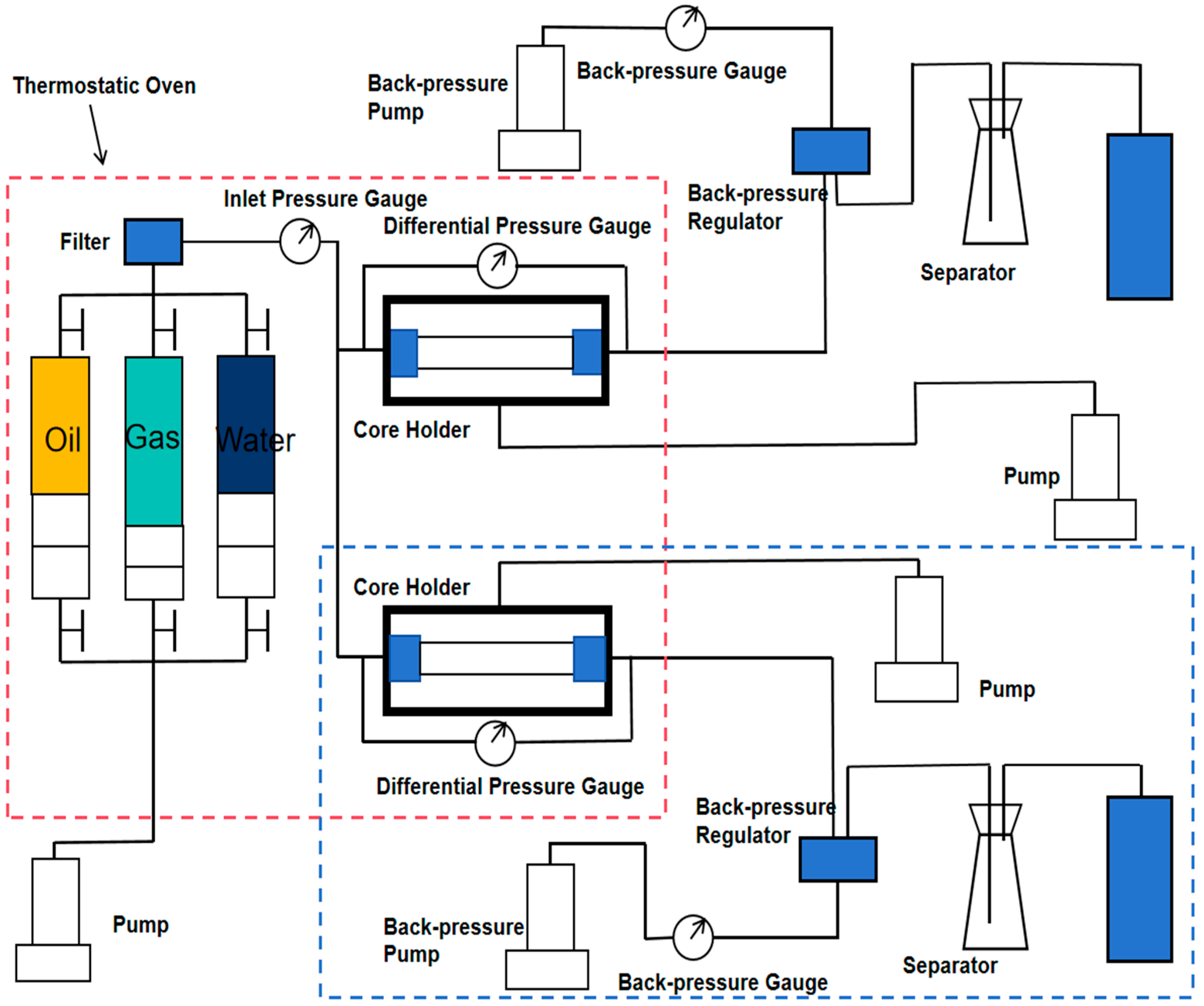
The temperature and pressure conditions for the long-core experiments were 139 °C and 57 MPa. The long-core flooding experiments were performed using a high-temperature, high-pressure long-core displacement system. The schematic diagram of the apparatus is shown in Figure 4. For parallel experiments, the setup includes the additional device indicated in the blue frame in Figure 4.
The experimental equipment mainly consists of five parts: a power supply system (Ruska fully automatic displacement pump, working pressure 0~70.00 MPa, accuracy 0.001 mL/min), a constant-temperature system (constant temperature oven, maximum temperature 200 °C), a one-dimensional physical model system, an oil–water separation system (Ruska gas meter and separator, liquid measurement accuracy 0.1 mL, gas measurement accuracy 0.001 mL), and a data acquisition system.
The experimental procedures were as follows:
(1)
Based on the selected medium–high-permeability and low-permeability long-core assemblies, the harmonic mean permeability was calculated. The cores were arranged according to the harmonic mean principle and installed in the long-core holder. Flow lines and valves were connected sequentially, and their connectivity and sealing performance were tested. Dead volume in the lines and valves was measured. A confining pressure was applied using the constant-pressure pump, the outlet valve was closed, and the system was evacuated for 24 h.
(2)
The intermediate container containing formation water was connected to the injection side, and constant-pressure saturation with formation water was started. Once the pressure stabilized for several hours, the injected volume was recorded to determine the actual pore volume.
(3)
The temperature and pressure of the long-core system were raised to formation conditions, with confining pressure 2.5 MPa higher than internal pressure. Irreducible water was established by injecting dead oil to displace formation water until no more water was produced. After stabilizing for 10 h, displacement continued and the produced water volume was recorded. Irreducible water saturation and oil saturation were calculated. When irreducible water saturation reached 25%, recombined formation fluid (formation crude oil) was injected to displace dead oil until the inlet and outlet gas–oil ratios were both 10.4 m3/m3. The system was stabilized overnight and displacement continued until the inlet and outlet gas–oil ratios matched. This completed the restoration of initial reservoir conditions.
(4)
Two injection modes were tested using the medium–high-permeability and low-permeability cores from layer III1 of well XH 11-1X. The tests were carried out under formation temperature and pressure. The two modes were: direct CO2 injection and CO2–water alternating injection (WAG, 1:1 volume ratio, 0.1 HCPV slug size, CO2 injected first). Data were recorded every 0.1 PV, including displacement time, pump readings, injection pressure, injection rate, confining pressure, and backpressure. The produced oil, gas, water volumes and the gas–oil ratio were also monitored. Each experiment ended when no oil was produced for 30 min. The recovery factor was then calculated.
(5)
After each experiment, the core was cleaned: first with petroleum ether and anhydrous ethanol, then blown with nitrogen, and the long-core system was dried.
(6)
After completing the single long-core flooding experiments for medium–high and low-permeability cores, both long cores were cleaned according to step (5). Bound water was re-established following step (3) and saturated with crude oil. Parallel long-core flooding experiments were then conducted using the CO2–water alternating injection mode (volume ratio 1:1, slug size 0.1 HCPV, CO2 injected first). The injection rate was 0.16 mL/min, and pressure drop was kept below 1.5 MPa. Displacement parameters and production data were recorded every 0.1 PV. Experiments ended when no oil was produced for 30 min. Recovery factors were calculated and the system was cleaned according to step (5) [31].

3. Results and Discussion

3.1. MMP Results

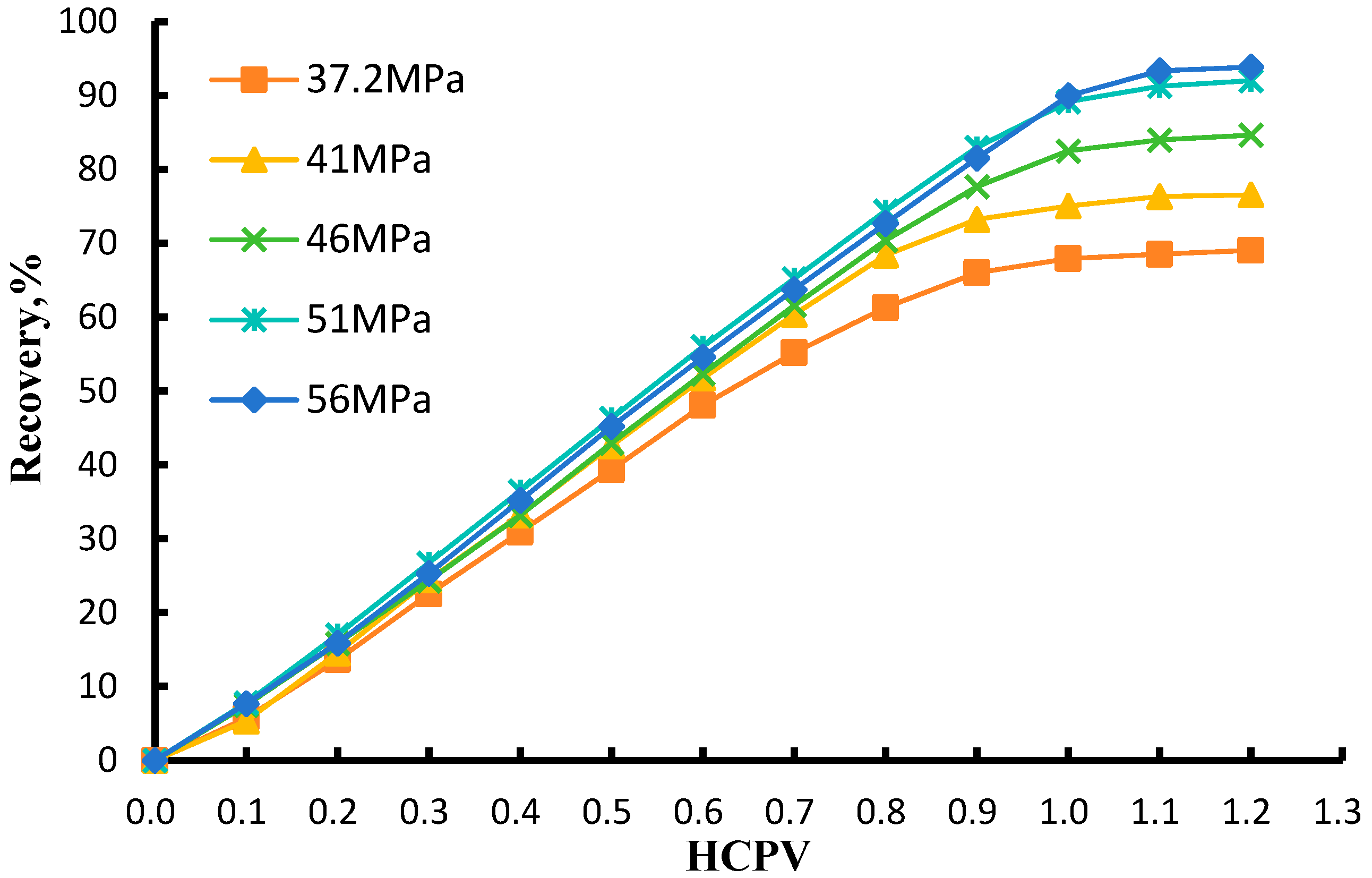
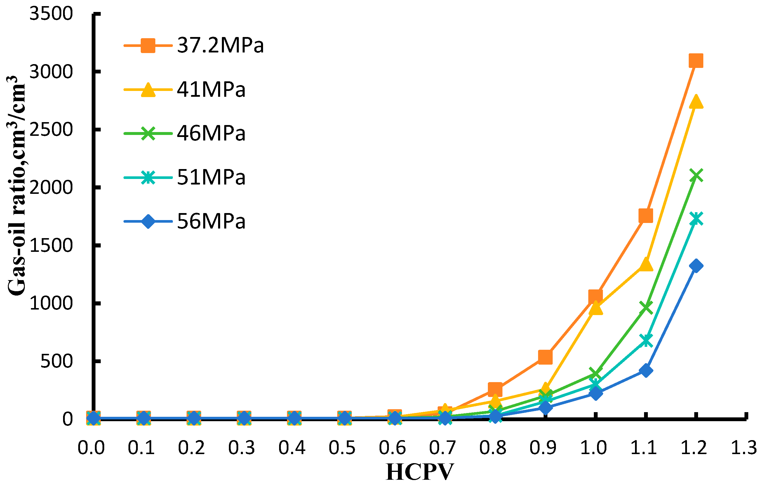
In this study, comprehensive CO2–oil minimum miscibility pressure (MMP) data were obtained from slim tube experiments. Figure 5 presents the relationship between oil recovery and CO2 injection at different pressures, whereas Figure 6 shows the variation in gas–oil ratio with CO2 injection under the same conditions. The experiments were conducted at pressures of 37.2, 41, 46, 51, and 56 MPa. These MMP tests define the pressure range over which the CO2–oil system transitions from immiscible to near-miscible conditions.
As shown in Figure 5, oil recovery increases progressively with CO2 injection in pore volumes (PV). Before gas breakthrough, the recovery rises at a high and nearly constant rate. When the injected CO2 exceeds about 0.6 PV, gas begins to break through along preferential flow paths, and the incremental recovery gradually slows and eventually levels off. A higher CO2 injection pressure results in a higher ultimate oil recovery and a later gas breakthrough. At an injection volume of 1.2 PV, oil recovery changes only slightly with further CO2 injection. The recovery values at 51 MPa and 56 MPa are very close. This indicates that once the pressure reaches a high level, the recovery exceeds 90%, and the difference in recovery between pressures becomes small.
As shown in Figure 6, CO2 breaks through earlier at low pressure and later at high pressure. Before gas breakthrough, the gas–oil ratio (GOR) at the outlet varies only slightly. After breakthrough, the GOR increases rapidly. At high pressure, however, the post-breakthrough increase in GOR is slower than that at low pressure. This is because a small amount of oil continues to be produced after high-pressure breakthrough, whereas oil production after low-pressure breakthrough is much lower or even becomes stagnant. As a result, the rise in GOR is less pronounced at high pressure. The timing of gas breakthrough also coincides with the stage when the growth rate of oil recovery begins to decline.
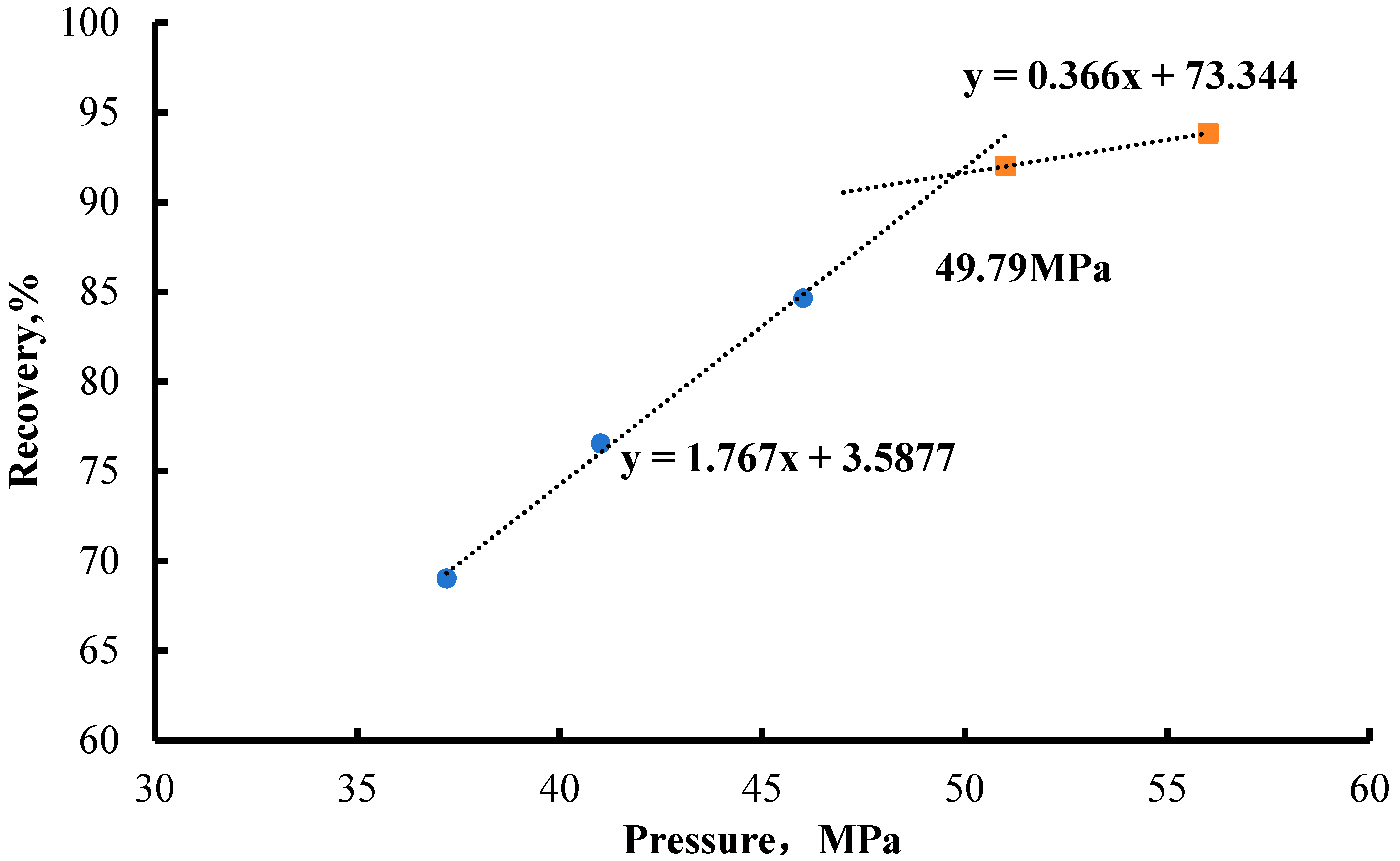
The oil recovery data were divided into immiscible and miscible displacement regimes, and the relationship between oil recovery and displacement pressure is shown in Figure 7. The intersection of the two fitted recovery trend lines corresponds to the minimum miscibility pressure of the CO2–oil system, which is 49.79 MPa. This value is slightly lower than the original reservoir pressure of 57 MPa. This condition is favorable for forming a stable miscible system between CO2 and crude oil, thereby significantly reducing interfacial tension and enhancing microscopic oil displacement efficiency. The result indicates that the reservoir has a favorable pressure basis for implementing miscible flooding. During development, CO2 injection should be prioritized before significant reservoir pressure depletion to fully implement the advantages of miscible displacement, improve oil recovery, and optimize injection performance.

3.2. Swelling Test Results

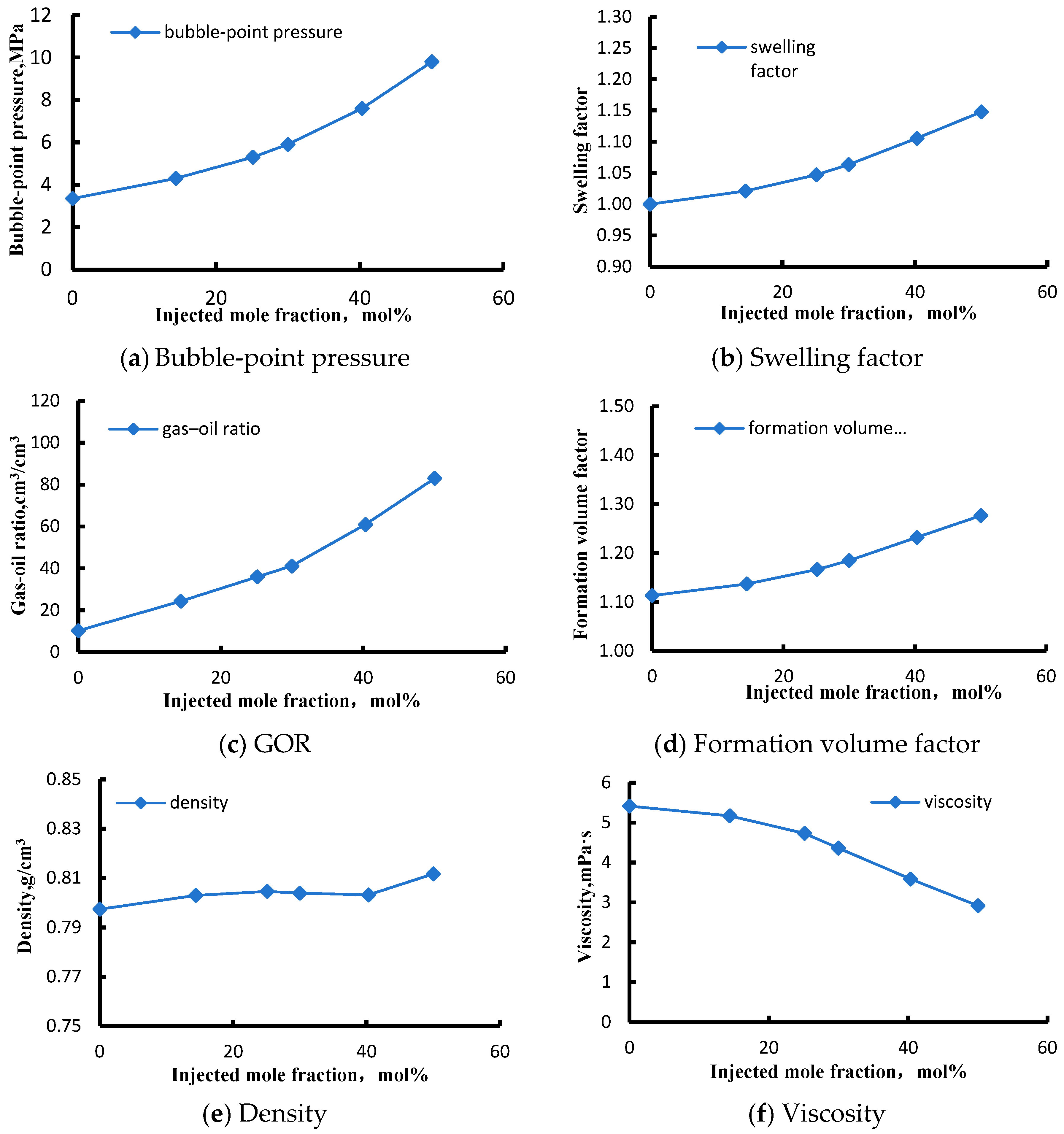
In this study, CO2 was injected into the recombined reservoir oil at different proportions under the reservoir temperature of 139 °C. The effects of CO2 concentration on bubble-point pressure, swelling factor, gas–oil ratio, formation volume factor, as well as density and viscosity were investigated.
As the CO2 mole fraction increased from 0 to 50.03%, these properties exhibited systematic variations. As shown in Figure 8a, the bubble-point pressure increased markedly from 3.35 MPa to 9.84 MPa, corresponding to a rise of 194%. The bubble-point pressure shows a clear monotonic increasing trend. This is attributed to changes in fluid composition caused by CO2 dissolution, which increases the proportion of light components and thereby elevates the bubble-point pressure. As shown in Figure 8b, the oil swelling factor exhibits an exponential increasing trend. When the CO2 mole fraction reaches 50%, the oil volume expands by a factor of 1.148, corresponding to an increase of 14.8%. This increase is relatively small compared with that of conventional light oils [32,33], indicating that at moderate CO2 concentrations, the ability of CO2 to swell waxy crude oil is limited. As shown in Figure 8c, the solution gas–oil ratio increases progressively with increasing CO2 content. When the CO2 mole fraction reaches 50%, the solution GOR is 82.98 m3/m3, which is 8.14 times higher than that of the original oil. This indicates a high CO2 solubility in the target crude oil, mainly because the original oil has a low bubble-point pressure and contains little dissolved gas, while CO2 solubility increases with pressure. As shown in Figure 8d, the oil formation volume factor increases from 1.113 to 1.276, corresponding to a rise of 4.6%, mainly due to the intermolecular interactions induced by CO2 dissolution. As shown in Figure 8e, the density of the reservoir oil increases slowly at first and then tends to stabilize, followed by a slight increase when the CO2 mole fraction reaches 50%. This behavior indicates that at low- to moderate-CO2 concentrations, the injected gas has a limited impact on oil density. However, at a CO2 mole fraction of 50%, the swelling capacity of the injected gas is relatively weak, leading to a small volume increase, while the mass increases more significantly. As a result, the oil density shows a slight rise. As shown in Figure 8f, the viscosity of the CO2–oil system decreases gradually with increasing CO2 content. When the CO2 mole fraction reaches 50%, the oil viscosity is reduced to 2.917 mPa·s, corresponding to a decrease of 46.10%, indicating that CO2 injection can effectively lower the viscosity of the target crude oil. However, compared with conventional light oils [13],the viscosity reduction is relatively limited, suggesting that the ability of CO2 to reduce the viscosity of heavy crude oil is moderate.
Overall, waxy crude oil is dominated by large-molecule alkanes, cycloalkanes, and aromatics, and the intermolecular interactions are mainly governed by van der Waals forces. CO2 molecules dissolve physically into the free volume between oil molecules. In this process, the mass increase exceeds the volume increase, leading to a slight rise in density [34], In contrast, for conventional light oils, the density may remain unchanged or even decrease after gas injection [35], which further confirms the limited swelling capacity of CO2 in waxy crude oil. Therefore, both the viscosity reduction and swelling effects of CO2 are relatively weak for waxy oil, and improvements in oil recovery rely more strongly on achieving miscible or near-miscible displacement. Compared with the limited improvement in oil viscosity due to CO2 dissolution, the miscible process plays a decisive role in enhancing oil recovery by significantly reducing interfacial tension and improving microscopic displacement efficiency. This understanding indicates that, in practical field development, reservoir pressure should be maintained above the minimum miscibility pressure to preserve stable miscible conditions and prevent excessive pressure depletion that could shift the displacement mechanism from miscible to immiscible, thereby reducing development effectiveness.

3.3. Long-Core Flooding Results

Based on the above experimental results, CO2 can achieve miscibility at pressures above 49.79 MPa. Under such conditions, its swelling and viscosity reduction are limited, and miscibility becomes the dominant mechanism for oil displacement. However, whether these effects can be fully realized at the porous-media scale depends on CO2 migration pathways, contact time, and interlayer flow distribution within the core [36,37,38]. Therefore, long-core flooding experiments are required to further evaluate the performance of CO2 flooding under different injection schemes, core permeabilities, and heterogeneous conditions. In this study, five groups of experiments were conducted, and the displacement schemes for each group are summarized in Table 10.
To ensure the representativeness and rationality of the experiments, a 1:1 gas–water ratio was used in the WAG process to balance the high flow rate of the gas phase with the mobility control of the water phase. The injection cycle was set to short slugs to enhance gas–water alternation and contact efficiency. Core permeabilities were selected across a range to characterize reservoir heterogeneity. It should be noted that due to potential changes in pore structure and bound water distribution caused by core cleaning and resaturation, repeated experiments cannot maintain strict consistency; therefore, this study employed a single representative experiment for analysis.

3.3.1. Effect of Displacement Method

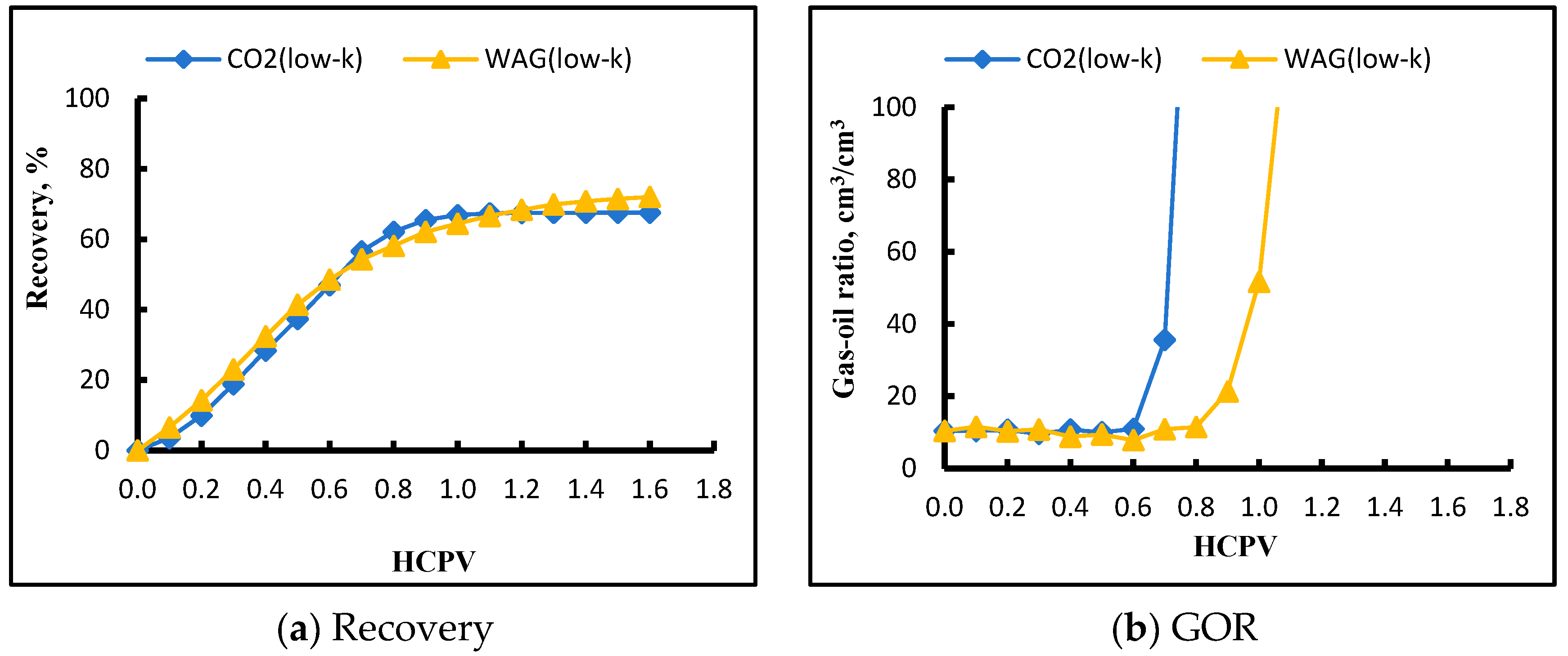
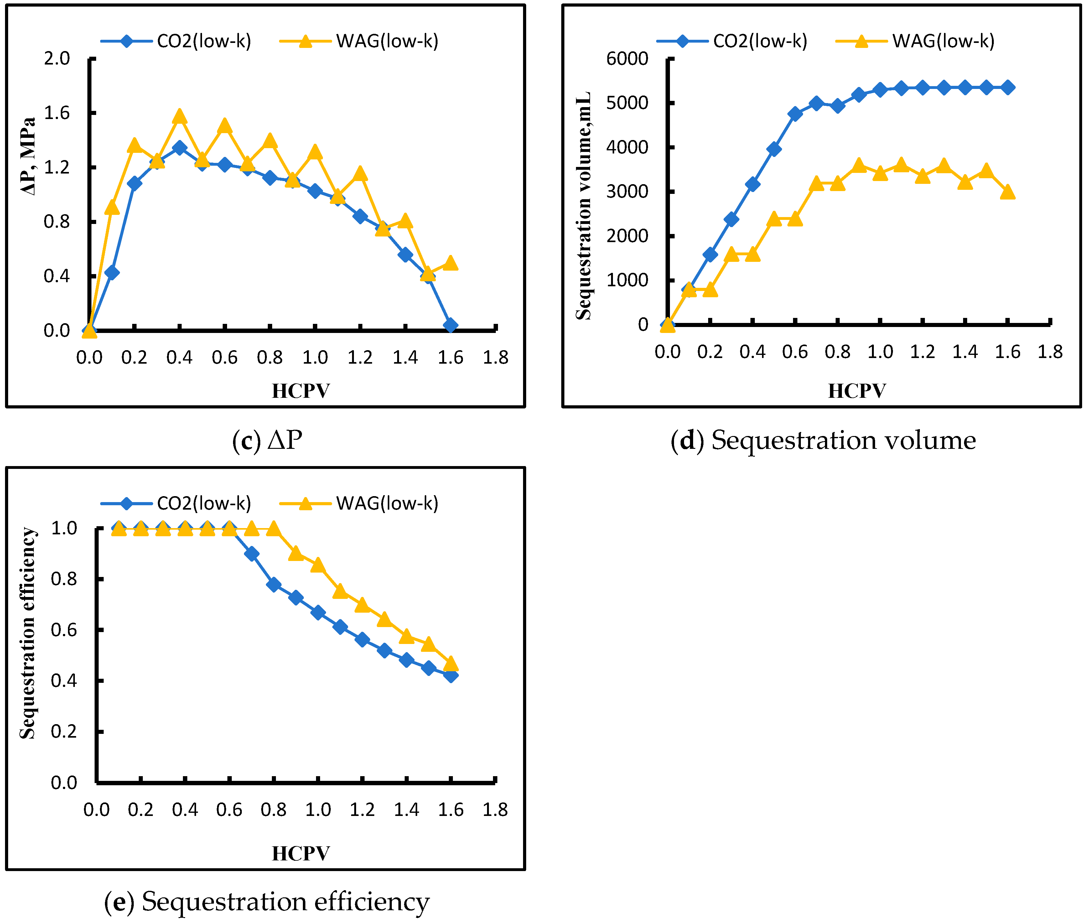
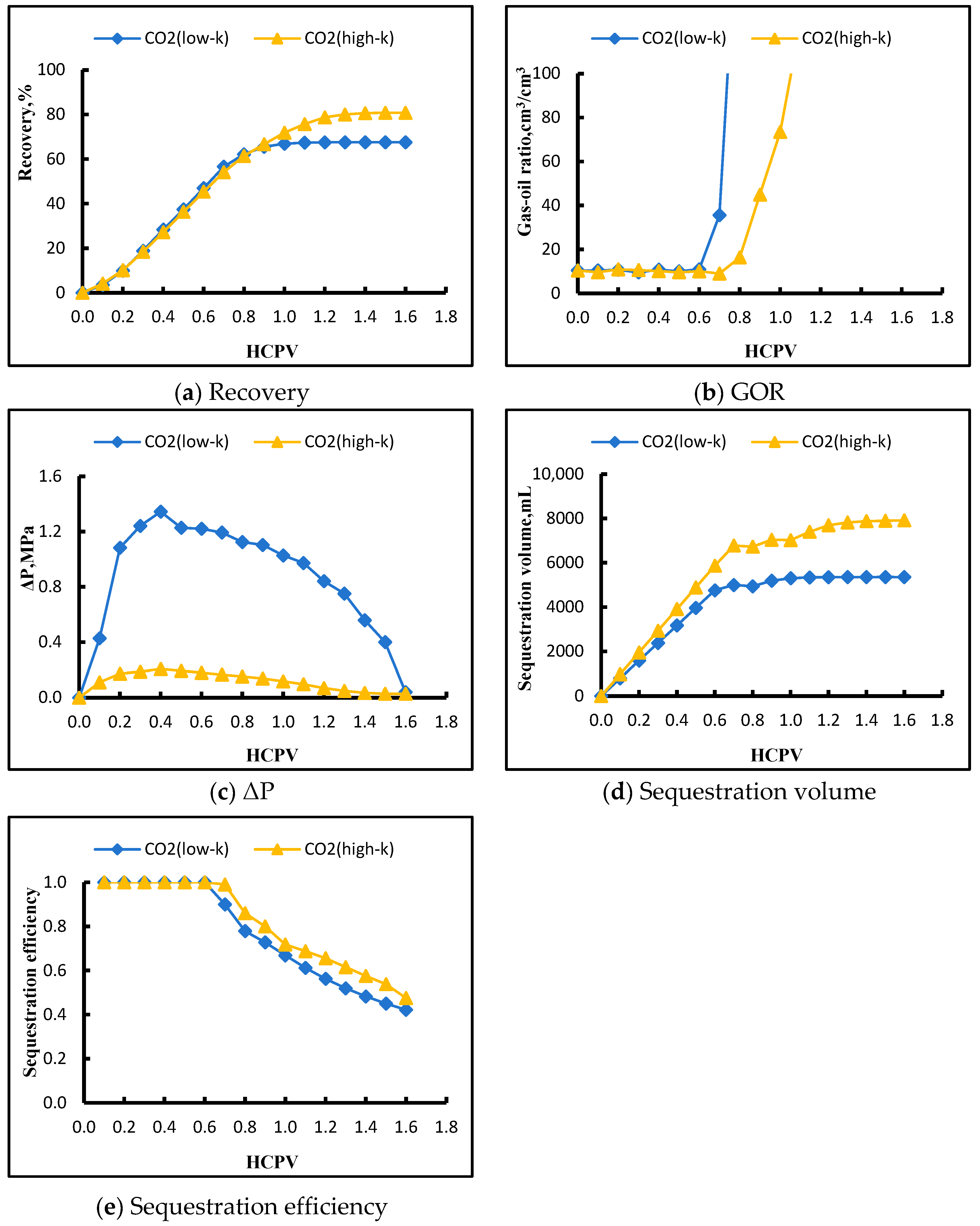
As shown in Figure 9, the low-permeability core CO2 flooding and WAG flooding processes are first compared to analyze the effect of displacement scheme on recovery. In Figure 9a, oil recovery increases continuously with injection volume. During CO2 injection, limited displacement occurs, and most of the injected mass is consumed in increasing system pressure. In contrast, due to its low compressibility, water exhibits a more pronounced displacement effect at the early stage. Consequently, in the early stage, WAG flooding achieves higher recovery than CO2 flooding. CO2 flooding surpasses during the mid-stage due to earlier breakthrough. In the late stage, during the stable recovery phase, WAG flooding again surpasses CO2 flooding. Compared with CO2 flooding alone, WAG flooding effectively improves recovery by enhancing the mobility ratio and expanding the swept volume [39]. It is noteworthy that the early-stage increase in oil recovery exhibits a concave rather than linear trend, which is more pronounced in CO2 flooding than in WAG flooding, reflecting a typical gas-drive characteristic where the gas initially builds up pressure before effectively displacing oil. In Figure 9b, the GOR rises sharply after breakthrough. Because WAG better controls mobility, gas breakthrough occurs significantly later than in CO2 flooding, and the recovery plateau is reached correspondingly later. Before gas breakthrough, oil recovery rises rapidly while the GOR remains stable. After breakthrough, recovery increases more slowly, while the GOR rises sharply. In Figure 9c, the pressure drop rapidly rises to a peak and then gradually declines. As the injection pressure increases, multi-contact between gas and liquid occurs, leading to miscibility. Once miscibility is achieved, the pressure drop begins to decrease as gas saturation slowly rises. The pressure drop for CO2 flooding is lower than for WAG flooding. Because water has higher viscosity, the injection of water causes fluctuations in the WAG pressure drop, whereas the flow resistance to be overcome by CO2 alone is smaller, resulting in a generally lower displacement pressure. Figure 9d,e show that the CO2 sequestration is higher in CO2 flooding than in WAG flooding, mainly because the total amount of CO2 injected in CO2 flooding is greater, and the water slugs in WAG can displace some of the injected CO2. However, in terms of sequestration efficiency (defined as the ratio of CO2 stored to CO2 injected), CO2 flooding reaches a final efficiency of 42.22%, whereas WAG achieves 46.93%, indicating that WAG provides higher overall CO2 sequestration efficiency. By regulating gas migration through the water slugs, WAG effectively suppresses rapid CO2 breakthrough and backflow, thereby significantly enhancing CO2 sequestration in the reservoir [23].
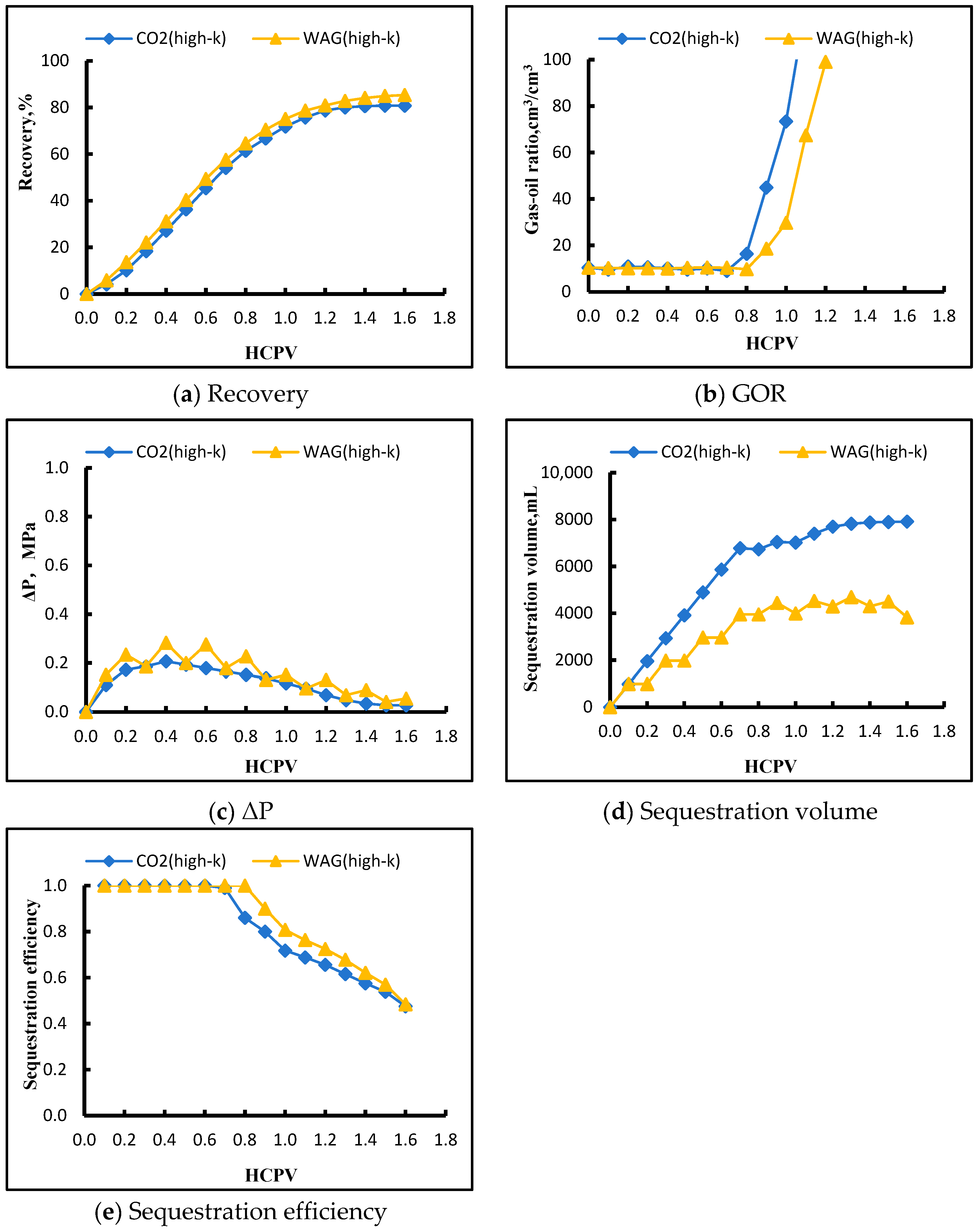
As shown in Figure 10, the same comparison was conducted for medium–high-permeability cores between CO2 flooding and WAG flooding, and the results are consistent with the trends observed in the low-permeability cores. However, under medium–high-permeability conditions, WAG flooding consistently achieves higher recovery than CO2 flooding, and no mid-stage overtaking occurs. The pressure drop in WAG flooding is also higher than in CO2 flooding, but the difference is smaller, as higher permeability facilitates water flow and reduces the impact of water viscosity on the pressure drop. The CO2 sequestration is larger in CO2 flooding than in WAG flooding, but the overall sequestration efficiency is higher in WAG flooding, similar to the observations in the low-permeability cores [40].
Overall, because CO2 has low viscosity and high mobility, CO2 flooding experiences earlier breakthrough compared with WAG flooding. After gas breakthrough, the recovery rate slows, the displacement pressure begins to decrease, and the sequestration efficiency declines. As a result, the ultimate recovery and sequestration efficiency of CO2 flooding are lower than those of WAG flooding, indicating a weaker displacement performance [41]. WAG flooding offers significant advantages in improving the mobility ratio, suppressing gas fingering, and expanding the swept volume, resulting in substantially higher oil recovery than continuous CO2 flooding [39,42], making it a preferred strategy for enhancing reservoir recovery.

3.3.2. Effect of Core Permeability

The above results indicate that both the oil recovery and CO2 sequestration efficiency of WAG flooding are higher than those of continuous CO2 flooding, making WAG flooding the preferred displacement strategy. The next step is to compare low-permeability and medium–high-permeability cores under the same displacement scheme to analyze the effect of core permeability on displacement performance.
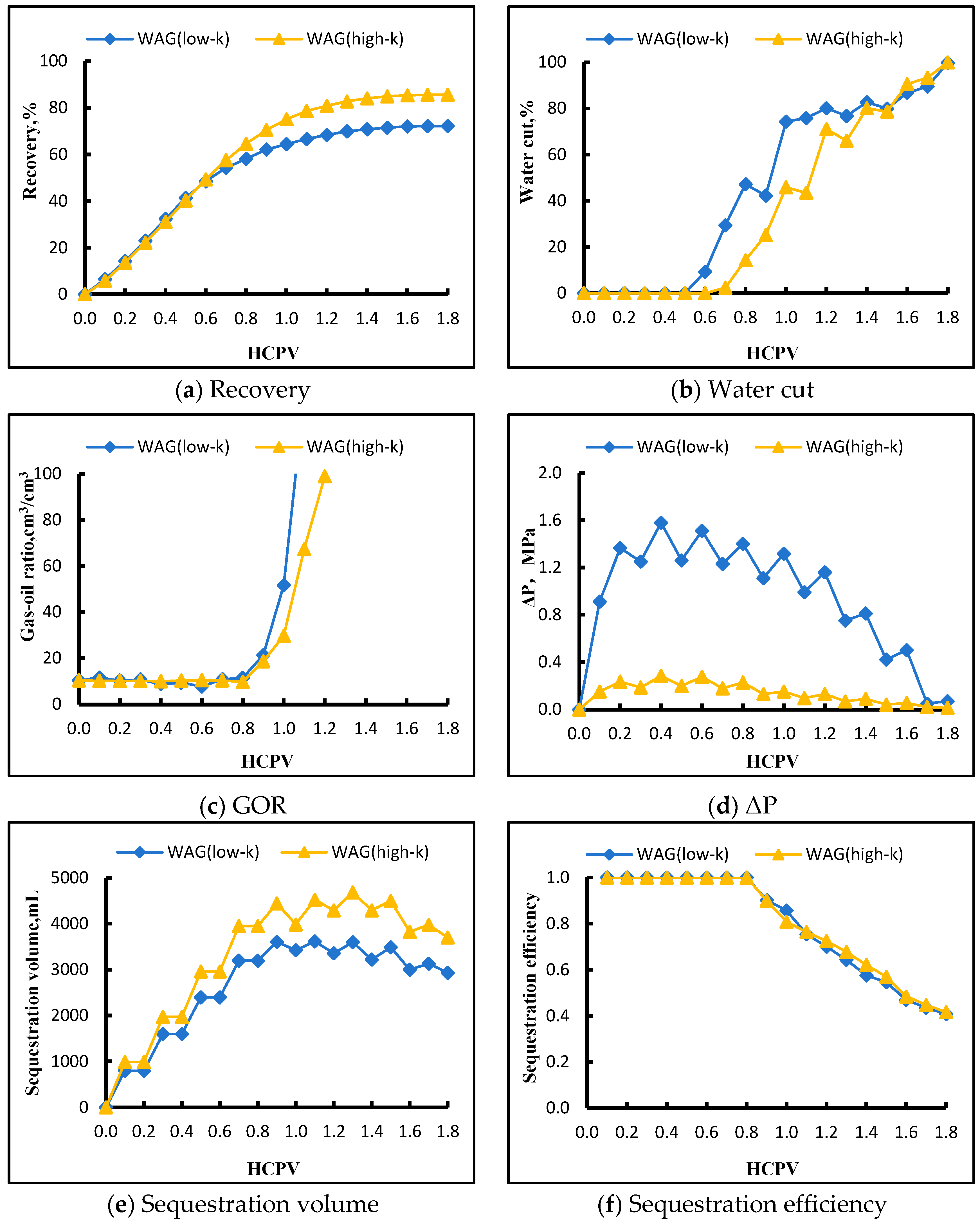
As shown in Figure 11, a comparison was first made between low-permeability and medium–high-permeability cores under WAG flooding. In Figure 11a, oil recovery increases continuously with injection volume, and the overall recovery level of medium–high-permeability cores is higher than that of low-permeability cores. In medium–high-permeability cores, the effect of heterogeneity is reduced, and the influence of high-permeability streaks is less pronounced, whereas low-permeability cores are more strongly affected by heterogeneity and flow disturbances. This indicates that higher permeability favors effective propagation and energy transfer of the gas–water phases within the pore network [43,44]. In Figure 11b, water cut also increases steadily with injection volume. In the early stage, the water cut in low-permeability cores rises faster than in medium–high-permeability cores. The phased interference of gas relative to water flow is more significant in the medium–high-permeability cores, delaying water breakthrough and moderating the increase in water cut. Figure 11c compares the GOR. Gas breakthrough times are similar for low- and medium–high-permeability cores, but the GOR rises more rapidly in low-permeability cores. This is mainly because their pore throats are smaller and connectivity is poorer, limiting effective oil flow paths. Once gas is introduced, it tends to create viscous fingers and flow through high-conductivity channels due to the adverse mobility ratio. Although gas breakthrough occurs at similar times, water breakthrough happens earlier in low-permeability cores. After water breakthrough, recovery in low-permeability cores decreases rapidly, highlighting the impact of permeability differences on recovery. In Figure 11d, the displacement pressure in medium–high-permeability cores is generally lower than in low-permeability cores, and the pressure drop during the gas-drive phase is more pronounced. Pressure fluctuations are smaller in medium–high-permeability cores, indicating lower flow resistance. Figure 11e,f show that the CO2 sequestration is higher in medium–high-permeability cores due to their larger pore volume, which allows more CO2 to be stored. The overall trend of sequestration efficiency is similar between the two permeability groups, suggesting that permeability has little effect on sequestration efficiency within the same reservoir. Since the mineral composition of the reservoir is similar due to the same sediment source and depositional environment, the pore–permeability structures of cores with different permeabilities are comparable. The permeability differences are mainly caused by variations in pore-throat size. Although low-permeability cores have smaller pore volumes and store less CO2, the amount of CO2 entering and leaving their pores is proportionally reduced. Therefore, due to the similarity in pore structure, the sequestration efficiencies of low- and medium–high-permeability cores are comparable [45].
As shown in Figure 12, a similar comparison was made between low-permeability and medium–high-permeability cores under CO2 flooding, and the results follow the same trend observed for WAG flooding. The overall oil recovery in medium–high-permeability cores is higher. CO2 breakthrough occurs earlier in low-permeability cores than in high-permeability cores, and the gas–oil ratio rises more rapidly in low-permeability cores. The displacement pressure in medium–high-permeability cores is generally lower than in low-permeability cores, following the same principle as in WAG flooding. However, unlike WAG, CO2 flooding lacks the interference of the water phase, so the pressure drop does not fluctuate as in WAG. The CO2 sequestration is also larger in medium–high-permeability cores, and because breakthrough occurs later, their sequestration efficiency is slightly higher than in low-permeability cores [46].
Overall, the capillary pressure differences between high- and low-permeability cores result in lower displacement efficiency in low-permeability cores. High-permeability cores have lower flow resistance, allowing oil in small pores to be mobilized more easily. The pore distribution in high-permeability cores is more uniform, enabling better CO2 contact. Under the presence of a water phase, the oil–gas interface in low-permeability cores is smaller or more easily segmented by water, leading to slower oil–gas movement compared with high-permeability cores [47,48,49]. For both CO2 flooding and WAG flooding, displacement performance under medium–high-permeability conditions is superior to that under low-permeability conditions.

3.3.3. Effect of Reservoir Heterogeneity

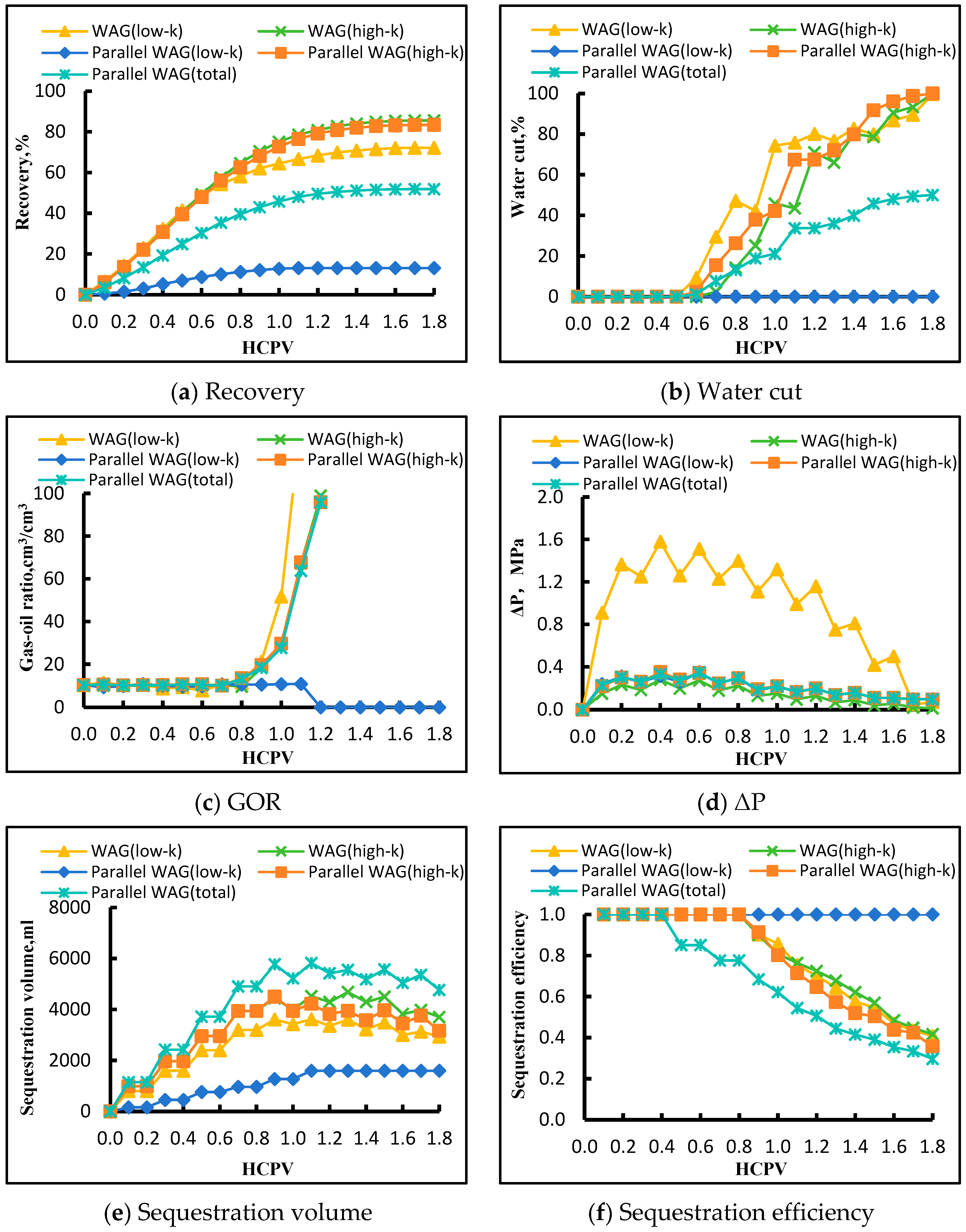
The above results are from single-core experiments, whereas parallel-core experiments account for the effects of heterogeneity during simultaneous injection and production. To focus solely on WAG mobility control and evaluate its applicability to typical permeability contrasts under joint injection and production, as well as to reveal differences in displacement mechanisms, a comparison between single-core and parallel-core WAG results was conducted. The results are shown in Figure 13.
In Figure 13a, the total oil recovery in parallel-core WAG flooding is lower than that of any single core, reflecting the fact that more heterogeneity is considered and a significant portion of the reserves remains untapped. During parallel-core flooding, the recovery in the high-permeability core is slightly lower than in the single-core test, while the recovery in the low-permeability core is much lower. After breakthrough in the high-permeability core, preferential flow paths are formed, greatly reducing flow resistance. Consequently, most of the injected fluid exits through the high-permeability core, and the low-permeability core is effectively bypassed, resulting in a very low recovery of only about 13%, far below that in single-core flooding. In Figure 13b, water cut in the high-permeability core rises slightly faster in parallel-core flooding than in single-core tests, whereas the low-permeability core stops flowing before gas–water breakthrough. This occurs because water preferentially flows through the high-permeability core once a dominant channel is established in the parallel configuration. In Figure 13c, the GOR continues to increase but is regulated by channeling. The trend in the high-permeability core is similar for both parallel-core and single-core flooding, whereas the low-permeability core in the parallel setup stops flowing after 0.3 HCPV following breakthrough in the high-permeability core. In Figure 13d, during parallel flooding, the pressure drops across the low- and high-permeability cores are identical, rather than exhibiting the large discrepancy observed in the single-core experiments. This is because, in the parallel system, the outlet backpressure is set to the same value and the inlets of both cores are connected, resulting in equal pressure drops across both cores. After breakthrough occurs in the high-permeability core, its flow resistance decreases substantially, leading to a lower pressure drop at the same flow rate. Consequently, the inlet pressure becomes insufficient to overcome the threshold pressure gradient of the low-permeability core, causing flow to cease in the low-permeability core. Figure 13e,f show that, under high-permeability conditions, both CO2 sequestration and sequestration efficiency are lower in parallel-core flooding than in single-core tests. For the low-permeability core, which is completely bypassed, CO2 does not breakthrough, and the sequestration and efficiency remain equivalent to only 0.4 HCPV in a single-core test. Moreover, the total sequestration efficiency in parallel-core flooding is lower than that of any single core, demonstrating that cross-flow and fluid diversion into high-permeability layers reduce the overall CO2 sequestration in heterogeneous systems.
Overall, under medium–high-permeability conditions, the final oil recovery in single-core WAG flooding reaches 85.56%, while in parallel-core flooding it is 83.39%. Under low-permeability conditions, the single-core recovery is 72.17%, whereas parallel-core recovery drops sharply to only 13.10%. For oil recovery characteristics, the parallel-core results are clearly influenced by interlayer heterogeneity. The comparison indicates that single-core WAG reflects displacement efficiency under relatively homogeneous conditions, whereas parallel-core WAG reveals the interference caused by interlayer flow diversion in heterogeneous conditions, which adversely affects overall displacement performance. The parallel-core results demonstrate that WAG alone is insufficient to control mobility under the permeability contrasts in this experiment, highlighting the need for stronger mobility-control measures. In practical development, if the effectiveness of WAG is limited, foam-assisted or polymer flooding using temperature-resistant chemicals can be considered as potential measures to improve oil recovery.
Recent studies have shown that the oil recovery efficiencies of CO2 flooding and WAG in tight and complex reservoirs vary significantly. Yu et al. [50] reported that in tight waxy systems, the WAG recovery efficiency is approximately 39%, which can be improved to over 63% under optimized conditions. Yang et al. [51] demonstrated that in complex core systems, WAG recovery ranges from about 48% to 74%. Han et al. [46] indicated that under low-permeability and strongly heterogeneous conditions, the recovery efficiency of CO2 flooding and WAG is approximately 16–27%, and is significantly affected by reservoir heterogeneity. In comparison, in this study, WAG achieves a recovery of 85.56% in homogeneous single-tube conditions, while it decreases to 83.39% and 13.10% under strongly heterogeneous parallel-tube conditions. These results suggest that WAG exhibits high displacement efficiency under homogeneous conditions, but its performance is significantly controlled by dominant flow channels under strong heterogeneity.
To study the impact of heterogeneity, we surveyed the permeability contrasts reported in dual-core experiments, as shown in Table 11. In strongly heterogeneous reservoirs, high-permeability channels typically dominate fluid flow, while the displacement efficiency in low-permeability regions is significantly reduced. Parallel-core experiments indicate that when the high/low-permeability ratio ranges from 2.5 to 12, fluid preferentially flows through the high-permeability channels, and the recovery in low-permeability zones is markedly limited [8,52,53]. These results suggest that optimizing WAG injection strategies in heterogeneous reservoirs—such as adjusting injection cycles, implementing mobility control, or modifying injection schemes—is critical for improving sweep efficiency in low-permeability zones and enhancing overall oil recovery. It is worth noting that the permeability contrast in our experiment is 6.04. According to our literature review, even in other studies where the permeability contrast reaches 12, no flow cessation in the low-permeability zones was observed. This indicates that highly waxy crude oil exhibits particular behavior in heterogeneous reservoirs.
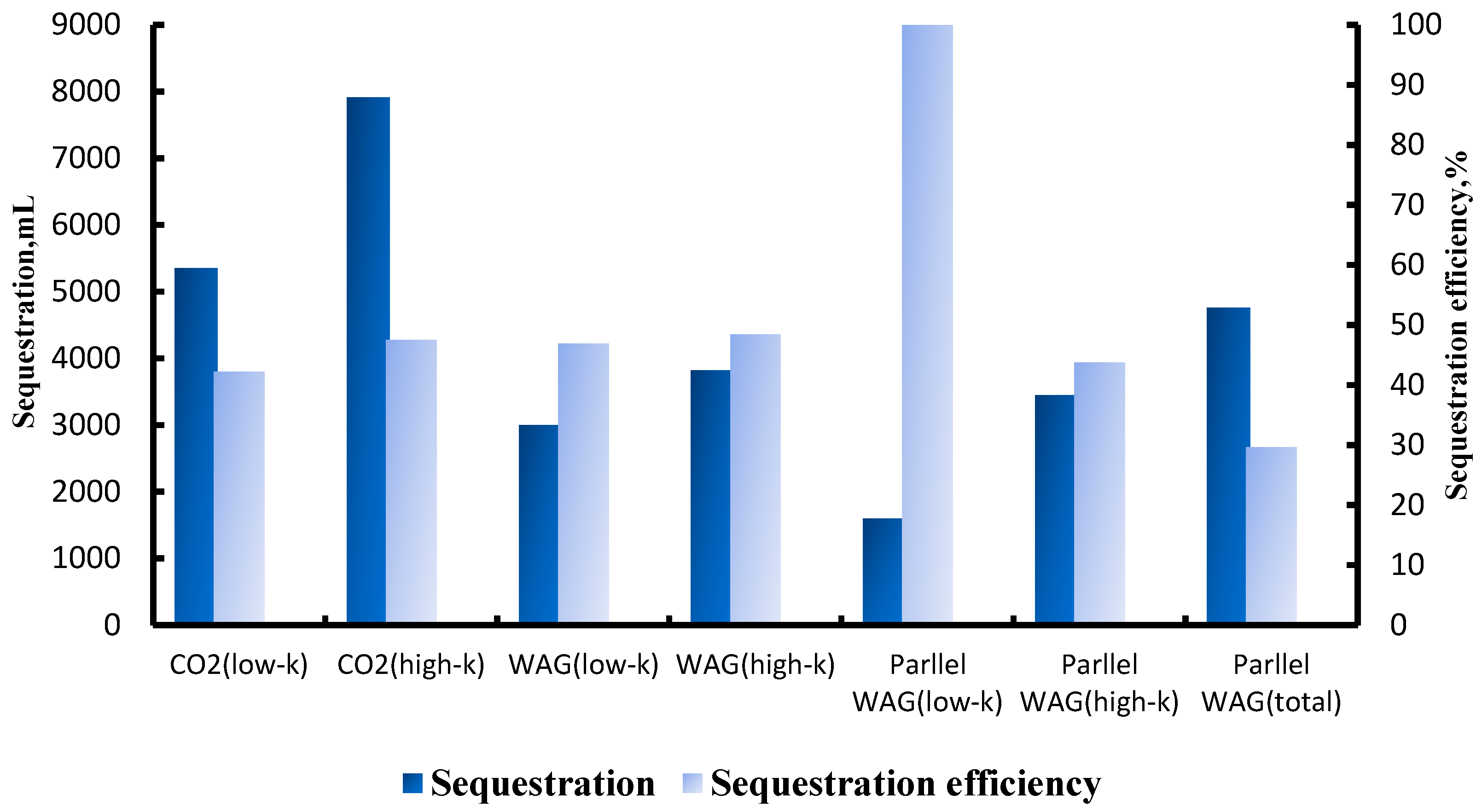
The experiments were terminated when the injection volume reached 1.6 HCPV, and the final CO2 sequestration and sequestration efficiency were compared, as shown in Figure 14. In single-core flooding, the CO2 sequestration is highest in the high-permeability core group under CO2 flooding; however, when comparing sequestration efficiency, the high-permeability core group under WAG flooding achieves higher efficiency. Notably, if the sequestration of the two cores in single-core WAG flooding is summed, the total far exceeds the CO2 sequestration in parallel-core WAG flooding. Similarly, the sequestration efficiencies of the two cores in single-core WAG flooding are higher than those in parallel-core WAG flooding. This difference arises because parallel-core WAG experiments introduce interlayer heterogeneity, creating strongly heterogeneous flow conditions. These experiments directly reflect the impact of reservoir heterogeneity on displacement performance and CO2 sequestration. In the parallel system, pronounced permeability contrasts enhance preferential flow paths, causing most of the fluid to bypass the low-permeability core through high-permeability channels, which reduces the amount of CO2 entering low-permeability zones and lowers overall retention.
In the late stage of displacement, once gas breakthrough occurs, no additional CO2 can be sequestered, and oil production gradually diminishes. Recovery approaches a plateau, while sequestration efficiency continues to decline. To optimize both oil recovery and CO2 sequestration simultaneously, there exists an optimal termination time.


4. Conclusions

This study systematically examines CO2 flooding and WAG flooding for waxy crude oil in heterogeneous reservoirs under high-temperature and high-pressure conditions, addressing challenges such as low displacement efficiency and uneven fluid distribution. By integrating slim tube experiments, CO2 swelling tests, and high-temperature/high-pressure long-core displacement experiments, the displacement performance of different injection schemes was compared under various permeability conditions and heterogeneous systems, considering phase behavior, changes in crude oil properties, and displacement characteristics at the porous-media scale. The main conclusions are as follows:
(1)
Under reservoir temperature and pressure conditions, CO2 can form a miscible system with the target waxy crude oil; however, its swelling and viscosity reduction are relatively limited, and oil displacement primarily relies on miscible contact.
(2)
Compared with CO2 flooding, WAG flooding effectively delays gas breakthrough, improves the fluid mobility ratio, and expands the swept volume, resulting in higher oil recovery and CO2 sequestration efficiency across different permeability conditions.
(3)
Core permeability has a significant impact on displacement performance. Medium- to high-permeability media exhibit lower flow resistance and more uniform fluid distribution, facilitating oil mobilization. Their recovery and CO2 sequestration rates are overall higher than those of low-permeability media.
(4)
In parallel-core heterogeneous systems, high-permeability channels readily form preferential flow paths, causing fluid to bypass low-permeability zones. This significantly reduces displacement efficiency in low-permeability layers and lowers the overall oil recovery and CO2 sequestration efficiency.

Author Contributions

Conceptualization, S.W. (Shuoshi Wang) and B.C.; Methodology, S.W. (Shengliang Wang), S.W. (Shuoshi Wang), Z.L. and B.C.; Validation, B.C. and N.Y.; Formal analysis, H.W., Z.W., X.F. and N.Y.; Investigation, S.W. (Shuoshi Wang) and B.C.; Resources, H.W., L.L., X.F., Z.L., Y.Z. and N.Y.; Data curation, B.C.; Writing—original draft, X.D. and B.C.; Writing—review & editing, S.W. (Shuoshi Wang), X.D. and N.Y.; Visualization, X.D.; Supervision, H.W., S.W. (Shengliang Wang), Z.W., S.W. (Shuoshi Wang) and N.Y.; Project administration, H.W., S.W. (Shengliang Wang) and Z.W. All authors have read and agreed to the published version of the manuscript.

Funding

This research work was partly supported by the National Natural Science Foundation of China (grant number 52404044) and the Sichuan Natural Science Foundation China (grant number 2026NSFSC1337).

Data Availability Statement

The original contributions presented in the study are included in the article, further inquiries can be directed to the corresponding author. The raw data supporting the conclusions of this article will be made available by the authors on request.

Conflicts of Interest

Authors Hongmei Wang, Shengliang Wang, Zhenjie Wang, Lijian Li, Xingya Fan, Zhaoyang Lu and Yujia Zeng were employed by the company PetroChina Huabei Oilfield Company. The remaining authors declare that the research was conducted in the absence of any commercial or financial relationships that could be construed as a potential conflict of interest.

References

  1. Jia, P.; Cui, C.; Wu, Z.; Yan, D. Influence of reservoir heterogeneity on immiscible water-alternating-CO2 flooding: A case study. Energy Geosci. 2024, 5, 100272. [Google Scholar] [CrossRef]
  2. Wang, Y.-Y.; Wang, X.-G.; Dong, R.-C.; Teng, W.-C.; Zhan, S.-Y.; Zeng, G.-Y.; Jia, C.-Q. Reservoir heterogeneity controls of CO2-EOR and storage potentials in residual oil zones: Insights from numerical simulations. Pet. Sci. 2023, 20, 2879–2891. [Google Scholar] [CrossRef]
  3. Jaber, A.K.; Awang, M.B. Field-scale investigation of different miscible CO2-injection modes to improve oil recovery in a clastic highly heterogeneous reservoir. J. Pet. Explor. Prod. Technol. 2017, 7, 125–146. [Google Scholar] [CrossRef]
  4. Lacey, M.; Hollis, C.; Oostrom, M.; Shokri, N. Effects of pore and grain size on water and polymer flooding in micromodels. Energy Fuels 2017, 31, 9026–9034. [Google Scholar] [CrossRef]
  5. Chen, X.; Yu, H.; Cao, A.; Yang, Z.; Li, W.; Niu, Z.; Chang, Y.; Du, M. Study on enhanced oil recovery mechanism of CO2 miscible flooding in heterogeneous reservoirs under different injection methods. ACS Omega 2023, 8, 24663–24672. [Google Scholar] [CrossRef] [PubMed]
  6. Le, N.N.H.; Sugai, Y.; Vo-Thanh, H.; Nguele, R.; Ssebadduka, R.; Wei, N. Experimental investigation on plugging performance of CO2 microbubbles in porous media. J. Pet. Sci. Eng. 2022, 211, 110187. [Google Scholar] [CrossRef]
  7. Rawat, A.; Khanikar, B.; Samanta, A.K.; Nguessan, P.; Mehta, B.; Sircar, A.; Desai, B.; Bera, A.; Bist, N. Experimental analysis of sequential water alternating CO2 gas injection for enhancing oil recovery in X-field sandstone reservoir of Cambay basin. Sci. Rep. 2025, 15, 21238. [Google Scholar] [CrossRef]
  8. Liu, Y.; Nie, F.; Zhang, B.; Liu, T.; Hong, Y. The Three-Dimensional Heterogeneous Simulation Study of CO2 Flooding in Low-Permeability Reservoirs. Processes 2024, 12, 1843. [Google Scholar] [CrossRef]
  9. Zhao, L.; Sang, G.; Ding, J.; Sun, J.; Liu, T.; Yao, Y. Research on the Timing of WAG Intervention in Low Permeability Reservoir CO2 Flooding Process to Improve CO2 Performance and Enhance Recovery. Energies 2023, 16, 7373. [Google Scholar] [CrossRef]
  10. Li, L.; Zheng, J.; Shi, Y.; Su, Y.; Hao, Y.; Chen, Z. Mechanisms of fluid migration and CO2 storage in low permeability heavy oil reservoirs using high-pressure microfluidic CO2 flooding experiment. Energy Fuels 2024, 38, 7997–8008. [Google Scholar] [CrossRef]
  11. Wang, L.; Zhao, Q.; Li, Z. Experimental investigation of carbon dioxide flooding in heavy oil reservoirs for enhanced oil recovery. Energy Rep. 2022, 8, 10754–10761. [Google Scholar] [CrossRef]
  12. Zhang, X.; Qi, Z.; Wang, B.; Zhou, Y.; Wang, C.; Xi, C.; Liu, P. Study on optimization and mechanism of CO2 injection to enhance oil recovery in mid-deep heavy oil reservoirs. Front. Energy Res. 2024, 12, 1375108. [Google Scholar] [CrossRef]
  13. Rezk, M.G.; Foroozesh, J. Phase behavior and fluid interactions of a CO2-Light oil system at high pressures and temperatures. Heliyon 2019, 5, e02057. [Google Scholar] [CrossRef]
  14. Fan, J.; Yao, M.; Fan, Z.; Chen, P.; He, K.; Wang, D. Unveiling the Effect of Complex Components on CO2-Oil Minimum Miscibility Pressure: Insights from Deep Convolutional Neural Networks. Energy Fuels 2024, 38, 6116–6126. [Google Scholar] [CrossRef]
  15. Song, G.; Meng, Y.; Zhang, C.; Zhao, Z.; Yang, Q. Comprehensive review of the determination and reduction of the minimum miscibility pressure during CO2 flooding. ACS Omega 2024, 9, 14747–14765. [Google Scholar] [CrossRef]
  16. Liu, Y.; Wang, S.; Zhao, W.; Yan, H.; Guo, P.; Zhang, J.; Bai, Z.; Wang, Z.; Ou, L. Multi-dimensional experimental study of hydrocarbon gas-assisted gravity drainage. Arab. J. Sci. Eng. 2023, 48, 17031–17048. [Google Scholar] [CrossRef]
  17. Nguele, R.; Sasaki, K.; Ghulami, M.R.; Sugai, Y.; Nakano, M. Pseudo-phase equilibrium of light and heavy crude oils for enhanced oil recovery. J. Pet. Explor. Prod. Technol. 2016, 6, 419–432. [Google Scholar] [CrossRef][Green Version]
  18. Wu, Z.; Feng, Q.; Tang, Y.; Zhou, D.; Lian, L. Experimental study on carbon dioxide flooding technology in the Lunnan Oilfield, Tarim Basin. Energies 2024, 17, 386. [Google Scholar] [CrossRef]
  19. Ding, Y.; Qiao, L.; Li, Z.; Luo, R.; Han, G.; Tan, J.; Liu, X. Experimental study on oil recovery characteristics of different CO2 flooding methods in sandstone reservoirs with NMR. Fuel 2025, 385, 134124. [Google Scholar] [CrossRef]
  20. Koyanbayev, M.; Hazlett, R.D.; Wang, L.; Hashmet, M.R. An experimental investigation of surfactant-stabilized CO2 foam flooding in carbonate cores in reservoir conditions. Energies 2024, 17, 3353. [Google Scholar] [CrossRef]
  21. Al-Bayati, D.; Saeedi, A.; Xie, Q.; Myers, M.B.; White, C. Influence of permeability heterogeneity on miscible CO2 flooding efficiency in sandstone reservoirs: An experimental investigation. Transp. Porous Media 2018, 125, 341–356. [Google Scholar] [CrossRef]
  22. Wang, Q.; Yang, S.; Lorinczi, P.; Glover, P.W.; Lei, H. Experimental investigation of oil recovery performance and permeability damage in multilayer reservoirs after CO2 and water–alternating-CO2 (CO2–WAG) flooding at miscible pressures. Energy Fuels 2019, 34, 624–636. [Google Scholar] [CrossRef]
  23. Li, Z.; Su, Y.; Li, L.; Hao, Y.; Wang, W.; Meng, Y.; Zhao, A. Evaluation of CO2 storage of water alternating gas flooding using experimental and numerical simulation methods. Fuel 2022, 311, 122489. [Google Scholar] [CrossRef]
  24. Luo, Y.; Qin, J.; Cai, J.; Tang, Y. The influencing factors of CO2 utilization and storage efficiency in gas reservoir. Appl. Sci. 2023, 13, 3419. [Google Scholar] [CrossRef]
  25. Zhao, S.; Fu, M.; Chen, J.; Li, Z.; Lin, J.; Zhang, S.; Wang, P. Experimental Study on the Alternate Oil Displacement Mechanism of CO2 and Modified Water in Low-Permeability Oil Layers. Energies 2024, 17, 6092. [Google Scholar] [CrossRef]
  26. Phukan, R.; Gogoi, S.B.; Tiwari, P. Enhanced oil recovery by alkaline-surfactant-alternated-gas/CO2 flooding. J. Pet. Explor. Prod. Technol. 2019, 9, 247–260. [Google Scholar] [CrossRef]
  27. Khan, M.; Raza, A.; Zahoor, M.K.; Gholami, R. Feasibility of miscible CO2 flooding in hydrocarbon reservoirs with different crude oil compositions. J. Pet. Explor. Prod. Technol. 2020, 10, 2575–2585. [Google Scholar] [CrossRef]
  28. Shabdirova, A.; Kozhagulova, A.; Samenov, Y.; Merbayev, R.; Niyazbayeva, A.; Shabdirov, D. Core flooding experiments on the impact of CO2-EOR on the petrophysical properties and oil recovery parameters of reservoir sandstones in Kazakhstan. Geosciences 2024, 14, 185. [Google Scholar] [CrossRef]
  29. Wei, J.; Shang, D.; Zhao, X.; Zhou, X.; Yang, Y.; Du, M. Experimental study on production characteristics and enhanced oil recovery during imbibition and huff-n-puff injection in shale reservoir. Capillarity 2024, 12, 41–56. [Google Scholar] [CrossRef]
  30. Wang, S.; Zhao, W.; Guo, P.; Gu, Z.; Yuan, N. HLD-based formulation prediction for degassed oil with equivalent minimum miscibility pressure. Energy Fuels 2024, 38, 2816–2829. [Google Scholar] [CrossRef]
  31. Xu, R.; Wang, S.; Guo, P.; Hukuang, H.; Yuan, N. Multi-scale investigation of CO2-WAG injection mechanisms in water-sensitive tight oil reservoirs. Arab. J. Sci. Eng. 2025, 50, 10327–10344. [Google Scholar] [CrossRef]
  32. Ahmadi, M.A.; Zendehboudi, S.; James, L.A. Hybrid connectionist model determines CO2–oil swelling factor. Pet. Sci. 2018, 15, 591–604. [Google Scholar] [CrossRef]
  33. Kristanto, D.; Yusgiantoro, L.A. Feasibility of CO2 injection for enhance oil recovery: A case study in the KMJ layer of HKY field. Int. J. Pet. Technol. 2023, 10, 14–25. [Google Scholar] [CrossRef]
  34. Yang, Y.; Liu, J.; Sheng, G.; Du, F.; Zheng, D. Analysis of the influence of CO2 pre-injection during hydraulic fracturing on enhanced oil recovery in shale reservoirs. Front. Earth Sci. 2022, 10, 1007620. [Google Scholar] [CrossRef]
  35. Ahmed, T.; Nasrabadi, H.; Firoozabadi, A. Complex flow and composition path in CO2 injection schemes from density effects. Energy Fuels 2012, 26, 4590–4598. [Google Scholar] [CrossRef]
  36. Fouad Hussein, A.; Wang, S.; She, W.; Khaleel, H.S. CO2 Huff and Puff under Relative Permeability Hysteresis Impact for Enhanced Oil Recovery in Gas Condensate Reservoir: A Sensitive Parametric Study. Energy Fuels 2025, 39, 21747–21766. [Google Scholar] [CrossRef]
  37. Li, T.; Wang, S.; Li, J.; Wang, D.; Tao, Z.; Wu, Y. Pore-Scale Numerical Simulation of CO2 Miscible Displacement Behavior in Low-Permeability Oil Reservoirs. Processes 2025, 13, 4073. [Google Scholar] [CrossRef]
  38. Qin, X.; Wang, H.; Wu, J.; Wang, G.; Wood, D.A.; Cai, J. Pore-scale evaluation of CO2 miscible displacement in porous rocks induced by convection and diffusion: Implications for CO2 geo-sequestration. Int. J. Coal Sci. Technol. 2025, 12, 54. [Google Scholar] [CrossRef]
  39. Fang, P.; Zhang, Q.; Zhou, C.; Yang, Z.; Yu, H.; Du, M.; Chen, X.; Song, Y.; Wang, S.; Gao, Y. Chemical-assisted CO2 water-alternating-gas injection for enhanced sweep efficiency in CO2-EOR. Molecules 2024, 29, 3978. [Google Scholar] [CrossRef]
  40. He, Y.; Qiu, S.; Qin, J.; Tang, Y.; Yu, W.; Wang, Y.; Du, X.; Rui, Z. Feasibility of CO2-water alternate flooding and CO2 storage in tight oil reservoirs with complex fracture networks based on embedded discrete fracture model. Energy 2025, 319, 135065. [Google Scholar] [CrossRef]
  41. Wang, Y.; Fan, Z.; Yang, C.; Weng, H.; He, K.; Wang, D. Pore-scale insights into CO2-EOR performance in depleted oil reservoirs by miscibility–compared with WAG injection. Geoenergy Sci. Eng. 2025, 250, 213839. [Google Scholar] [CrossRef]
  42. Dutta, R.; Kundu, G.; Mousavi Mirkalaei, S.M.; Chakraborty, R.; Yomdo, S.; Mandal, A. Evaluation of potential of CO2-enhanced oil recovery (EOR) and assessment of capacity for geological storage in a mature oil reservoir within upper Assam Basin, India. Energy Fuels 2024, 38, 14096–14118. [Google Scholar] [CrossRef]
  43. Su, X.; Yue, X.-a. Mechanism study of the relation between the performance of CO2 immiscible flooding and rock permeability. J. Pet. Sci. Eng. 2020, 195, 107891. [Google Scholar] [CrossRef]
  44. Yue, P.; Zhang, R.; Sheng, J.J.; Yu, G.; Liu, F. Study on the influential factors of CO2 storage in low permeability reservoir. Energies 2022, 15, 344. [Google Scholar] [CrossRef]
  45. Luo, Q.; Li, Y.; Sun, H.; Liu, S.; Yu, Y.; Yang, Z. Research on CO2–WAG in Thick Reservoirs: Geological Influencing Factors and Random Forest Importance Evaluation. ACS Omega 2024, 9, 34118–34127. [Google Scholar] [CrossRef]
  46. Han, W. The Influence of Injection Modes on CO2 Flooding and Storage in Low-Permeability Reservoirs. Energies 2026, 19, 480. [Google Scholar] [CrossRef]
  47. Cheng, Y.; Qu, Y.; Cheng, X.; Ni, J.; Zhou, Z.; Lan, S.; Yang, Z.; Wei, L.; Wu, H.; Sun, W. Microscopic mechanism of CO2 displacement oil in different pore throat radius segments of tight sandstone reservoirs. ACS Omega 2024, 9, 35113–35130. [Google Scholar] [CrossRef]
  48. Pi, Y.; Su, Z.; Liu, L.; Wang, Y.; Zhang, S.; Li, Z.; Zhou, Y. Investigation of the Influence of Formation Water on the Efficiency of CO2 Miscible Flooding at the Core Scale. Processes 2023, 11, 2954. [Google Scholar] [CrossRef]
  49. Wang, H.; Tian, L.; Chai, X.; Wang, J.; Zhang, K. Effect of pore structure on recovery of CO2 miscible flooding efficiency in low permeability reservoirs. J. Pet. Sci. Eng. 2022, 208, 109305. [Google Scholar] [CrossRef]
  50. Yu, H.; Fu, W.; Zhang, Y.; Lu, X.; Cheng, S.; Xie, Q.; Qu, X.; Yang, W.; Lu, J. Experimental study on EOR performance of CO2-based flooding methods on tight oil. Fuel 2021, 290, 119988. [Google Scholar] [CrossRef]
  51. Yang, G.; Bai, Y.; Song, Y.; Metwally, A.S.M.; Mahmoud, O. An experimental study to measure oil recovery factor by chemical agents and carbon dioxide after waterflooding. Sci. Rep. 2022, 12, 9464. [Google Scholar] [CrossRef] [PubMed]
  52. Wang, X.; Zhang, J.; Yuan, G.; Wang, W.; Liang, Y.; Wang, H.; Li, Y. Effect of emulsification on enhanced oil recovery during surfactant/polymer flooding in the homogeneous and heterogeneous porous media. Geofluids 2021, 2021, 6674185. [Google Scholar] [CrossRef]
  53. Zhou, X. Novel insights into IOR/EOR by seawater and supercritical CO2 miscible flooding using dual carbonate cores at reservoir conditions. In Proceedings of the IOR 2015-18th European Symposium on Improved Oil Recovery, Dresden, Germany, 14–16 April 2015; p. cp-445-00016. [Google Scholar]
Figure 1. Comparison of component composition between XH crude oil and recombined crude oil.
Energies 19 01777 g001
Figure 2. Slim tube experiment setup. (red dashed box is oven).
Energies 19 01777 g002
Figure 3. Swelling test experiment setup.
Energies 19 01777 g003
Figure 4. Long-core flooding experiment setup (blue dashed box is optionable setup for parallel core flooding).
Energies 19 01777 g004
Figure 5. Relationship between recovery and CO2 injection volume at different pressures.
Energies 19 01777 g005
Figure 6. Relationship between gas–oil ratio and CO2 injection volume under different pressures.
Energies 19 01777 g006
Figure 7. Minimum miscibility pressure of the CO2–oil system.
Energies 19 01777 g007
Figure 8. Variation in different parameters with CO2 injection volume.
Energies 19 01777 g008
Figure 9. Low-permeability core’s relationship between injected pore volume and various parameters for CO2 flooding and WAG.
Energies 19 01777 g009aEnergies 19 01777 g009b
Figure 10. High-permeability core’s relationship between injected pore volume and various parameters for CO2 flooding and WAG.
Energies 19 01777 g010
Figure 11. WAG experiment relationship between injected pore volume and various core flooding parameters.
Energies 19 01777 g011
Figure 12. CO2 continuous injection experiment relationship between injected pore volume and various core flooding parameters.
Energies 19 01777 g012
Figure 13. Relationship between injected pore volume and various parameters for single-core WAG and parallel-core WAG.
Energies 19 01777 g013
Figure 14. Comparison of experimental CO2 sequestration volume and sequestration efficiency.
Energies 19 01777 g014
Table 1. Long-core experimental conditions.
AuthorPorosity (%)Permeability (mD)Oil Viscosity (mPa·s)Oil APITemperature (°C)Pressure (MPa)Injection Method
Koyanbayev et al. [20]18–22175–6302–5 (light oil)>35°20–803.45–10.34CO2/WAG/CO2 foam
Zhao et al. [25]18–20100–30012 (dead oil viscosity)-7018WAG
Ding et al. [19]14.7–17.9521.5–95.73.8 (@ reservoir temperature 75 °C)-7525CO2/WAG
Phukan et al. [26]17–252.5–3/25–304.46–9.3 (dead oil viscosity)23–31°708–12WAG/SAG/SsAG/ASAG
Khan et al. [27]---25–35°50–7014.8–17.2CO2
Shabdirova et al. [28]23–24.6233–349--25-Continuous CO2 flooding
Wei et al. [29]8.1–9.30.023–0.038.671 (dead oil viscosity)-60–80>10CO2 huff-and-puff
Table 2. Comparison of associated gas component data.
CompositionAssociated Gas Composition, mol%
Target Associated GasReal Gas
CO212.4916.04
N24.330.69
C162.1665.6
C27.498.59
C34.056.15
iC41.710.81
nC43.950.94
iC51.930.7
nC51.820.35
C60.010.14
Table 3. Basic parameters of formation water.
pH Value6.2ColorPale Yellow
Cations (mg/L)Na+ + K+40,065.8Anions (mg/L)Cl63,810
Mg2+116.6SO42−1344.8
Ca2+1691.4HCO3533.9
CO32−
OH
Total 41,873.8Total65,688.7
Trace Elements (mg/L)I36.6Total Mineralization107,562.5
B175.1
Water Type and CharacteristicsSulín Classification
Water Type:CaCL2
Water Characteristic Coefficients:C(Na+)/C(Cl) = 0.97
C(Cl-Na+)C(1/2 Mg2+) = 5.96
Table 4. Data comparison between XH dead oil and existing dead oil.
CompositionDead Oil Compositions, mol%
XH Dead OilExisting Dead Oil
C1–41.882.30
C5–1226.0025.82
C13–2433.6033.35
C25+38.5338.52
Table 5. Recombined formation crude oil results for XH 11-5-C1 formation.
Crude Oil Physical PropertiesTemperature, °CTargetResultDeviation
Gas–oil ratio, m3/m3-10.410.2<3%
Bubble point pressure, MPa1393.383.41<1%
Dead oil density, g/cm3200.87930.8807<2%
Dead Oil viscosity, mPa·s6035.7735.62<1%
Formation volume factor @ bubble point1391.1141.111<1%
Formation crude oil density, g/cm31390.84080.8419<2%
Formation crude oil viscosity, mPa·s1395.4125.396<3%
Table 6. Comparison of target wellbore fluid and actual prepared wellbore fluid.
CompositionFormation Oil Components, mol%
Actual Prepared Wellbore FluidTarget Wellbore Fluid
N2 + CO210.372.26
C1–45.2612.32
C5–1224.7423.00
C13–2428.7229.07
C25+30.9133.34
Table 7. Basic parameters of medium–high-permeability core.
Core IDLength, cmPermeability, 10−3, μm2Porosity, %
XH-11-1X 1956.98102.519.87
XH-11-1X 1595.5912220.61
XH-11-1X 1106.98126.116.56
XH-11-1X 1616.9983.1720.17
XH-11-1X 1566.83138.120.04
XH-11-1X 1576.99138.220.4
XH-11-1X 2016.9982.5418.72
XH-11-1X 2026.99141.219.72
XH-11-1X 2-16.9970.516.95
XH-11-1X 1116.99151.416.52
XH-11-1X 203764.3420.24
XH-11-1X 1946.99156.919.98
XH-11-1X 1556.86163.120.32
XH-11-1X 3-16.99164.820.44
Table 8. Basic parameters of low-permeability cores.
Core NumberLength, cmPermeability, 10−3, μm2Porosity, %
XH-11-1X 2067.0019.7317.49
XH-11-1X 46.9921.9917.11
XH-11-1X 2136.9914.8617.49
XH-11-1X 2156.9911.5414.9
XH-11-1X 1626.9910.3119.37
XH-11-1X 2077.0010.0715.92
XH-11-1X 2217.009.7117.04
XH-11-1X 2046.9831.7719.41
XH-11-1X 1677.0041.8617.4
XH-11-1X 1687.0042.4913.31
XH-11-1X 2056.9943.5819.49
XH-11-1X 1506.9951.5219.66
XH-11-1X 1636.9951.7219.18
XH-11-1X 1666.9557.7217.89
Table 9. Slim tube parameters.
Length, mInner Diameter, mmFilling Material TypeSand Particle Mesh Size, MeshPore Volume, mLPermeability, D
153.87Quartz sand4079.314
Table 10. Experimental conditions for five groups of long-core flooding tests.
No.Experiment TypePermeability, 10−3 um2Porosity,%Pore Volume, mLPermeability ContrastInjection Rate, mL/minInjection
Strategy
1Low-permeability core CO2 flooding (CO2 low-k)19.7917.5571.5\0.08Continuous CO2 flooding
2Medium–high-permeability core CO2 flooding (CO2 high-k)119.4418.1189.7\0.08Continuous CO2 flooding
3Low-permeability core WAG flooding (WAG low-k)19.7917.5572.3\0.08Volume ratio 1:1, slug size 0.1 HCPV (CO2 injected first)
4Medium–high-permeability core WAG flooding (WAG high-k)119.4418.1190.1\0.08Volume ratio 1:1, slug size 0.1 HCPV (CO2 injected first)
5Parallel-core WAG flooding (parallel WAG)19.79/119.4417.55/18.1172.3/90.36.040.16Volume ratio 1:1, slug size 0.1 HCPV (CO2 injected first)
Table 11. Permeability contrast.
AuthorExperiment TypePermeability (mD)Permeability Contrast
Liu et al. [8]Parallel of Two Tubes CO2 Miscible75/155:1
Zhou et al. [53]Parallel Tubes831/6912:1
Wang et al. [52]Parallel Tubes1250/5002.5:1
Disclaimer/Publisher’s Note: The statements, opinions and data contained in all publications are solely those of the individual author(s) and contributor(s) and not of MDPI and/or the editor(s). MDPI and/or the editor(s) disclaim responsibility for any injury to people or property resulting from any ideas, methods, instructions or products referred to in the content.