Article

Modelling Techniques of Proton Exchange Membrane Fuel Cells (PEMFC): Electrical Engineer’s View †

by
Nisitha Padmawansa
,
Kosala Gunawardane
*,
Sahan Neralampitiyage
and
Dylan Lu
School of Electrical and Data Engineering, Faculty of Engineering and IT, University of Technology Sydney, Sydney 2007, Australia
*
Author to whom correspondence should be addressed.
This paper is an extended version of our paper published in 2023 IEEE International Conference on Energy Technologies for Future Grids (ETFG), Wollongong, Australia, 3–6 December 2023; pp. 1–7.
Energies 2026, 19(6), 1577; https://doi.org/10.3390/en19061577
Submission received: 27 January 2026 / Revised: 12 March 2026 / Accepted: 17 March 2026 / Published: 23 March 2026
(This article belongs to the Section A5: Hydrogen Energy)

Abstract

Proton exchange membrane fuel cells (PEMFCs) play a key role in hydrogen-based energy systems; however, accurate and practical modelling remains challenging due to system nonlinearities, parameter variability, and degradation effects. This paper presents a low-complexity parameter estimation methodology for a simplified PEMFC equivalent circuit model using current-switching techniques. The approach enables direct extraction of key parameters, including internal resistance and capacitance, from transient voltage responses without requiring complex optimization or large datasets. Experimental validation was conducted using 100 W and 1 kW PEMFC systems under current loading and interruption conditions. The results demonstrate good agreement between measured and simulated voltage responses, with a maximum error below 10% and typical error levels in the range of ~1.4–3%. Compared to conventional mechanistic and data-driven models, the proposed method significantly reduces computational complexity and measurement requirements while maintaining high predictive accuracy. Moreover, the combination of the simplified equivalent circuit model with current-switching-based parameter estimation offers an effective and practical tool for electrical engineers, enabling real-time monitoring, control-oriented modelling, and seamless integration with power electronic systems. The proposed approach is particularly suitable for applications in DC microgrids and digital twin-based monitoring of hydrogen energy systems.

1. Introduction

Hydrogen is the most abundant element in the universe, accounting for approximately 75% of normal matter by mass [1]. However, hydrogen rarely exists in nature in its pure molecular form (H2) and therefore must be produced from other compounds such as water, hydrocarbons, or biomass. In the context of the global transition toward low-carbon energy systems, hydrogen is increasingly viewed as a promising energy carrier rather than a primary energy source. In hydrogen-based applications, fuel cells (FCs) convert the chemical energy of hydrogen directly into electrical energy. Compared to conventional power sources such as internal combustion engines and batteries, FCs offer several advantages, including high energy efficiency, zero carbon emissions at the point of use, and scalability across diverse applications. In particular, the production of green hydrogen through water electrolysis using surplus renewable energy from wind and solar systems has emerged as an important pathway for energy storage and deep decarbonization. This approach not only provides a clean hydrogen supply for PEMFC systems but also helps mitigate the intermittency and variability of renewable energy generation by converting excess electricity into a storable energy carrier [2]. Compared to conventional power sources such as internal combustion engines and batteries, FCs offer several advantages, including high energy efficiency, zero carbon emissions, and scalability across diverse applications [3,4,5]. FCs are employed across various sectors, such as transportation, stationary power generation, portable power systems, and aerospace technologies [6,7,8,9,10]. Due to these benefits, global interest in hydrogen has grown exponentially, leading many countries, including Australia, Japan, Korea, China, and Singapore, to incorporate hydrogen into their national energy strategies [11,12]. With the increasing adoption of FCs, regulatory standards have been established to ensure safe and efficient implementation. Table 1 summarizes the existing FC standards [13,14,15,16,17,18,19,20,21]. Among these, certain standards focus specifically on evaluating FC performance across different applications. As performance assessments—particularly during the design and early development stages—are often conducted through simulation-based analyses, the accuracy of these evaluations strongly depends on the fidelity of the employed FC models. Consequently, there is an increasing demand for advanced FC models capable of accurately capturing the dynamic response, transient characteristics, and nonlinear behaviour of FC systems under varying operating conditions. However, depending on the application, the interest performance characteristics of FCs vary. As a result, various FC equivalent circuit models have been developed, prioritizing the dynamics most relevant to the intended application.
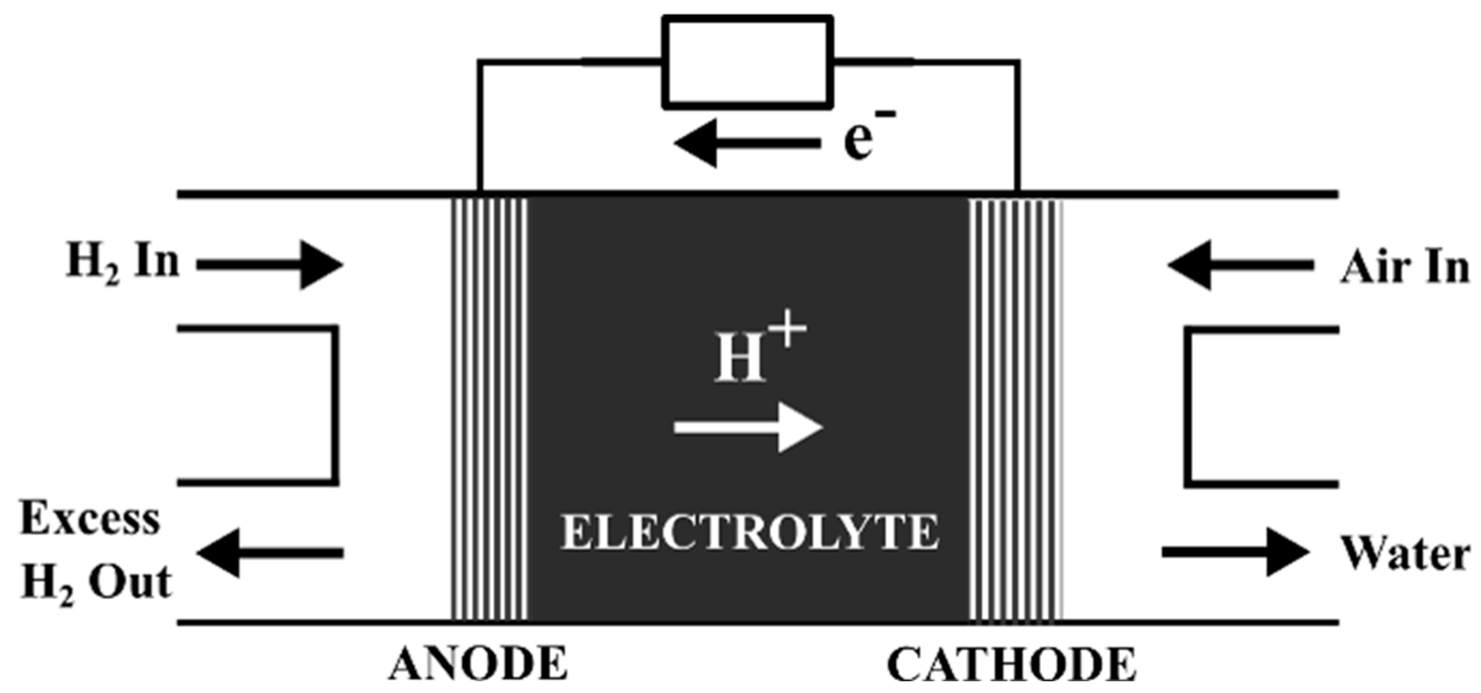
In order to have a better understanding of the FC models, the basic operation of the FC needs to be analysed. As illustrated in Figure 1, a typical FC comprises three primary components: an anode, a cathode, and an electrolyte. Hydrogen is supplied to the anode, where it undergoes electrochemical oxidation, splitting into protons (H+) and electrons (e), as represented by the following Reaction (1) [30]:
2 H 2 4 H + + 4 e
The generated protons then migrate through the electrolyte (commonly referred to as the proton-exchange membrane) to the cathode. The membrane is selectively permeable, allowing only protons to pass while blocking electrons. Consequently, electrons travel through an external circuit, generating an electric current before reaching the cathode. At the cathode, protons, electrons, and oxygen (typically sourced from ambient air) combine to form water and heat as byproducts, as described by Reaction (2):
O 2 + 4 H + + 4 e 2 H 2 O + h e a t
This process, known as the oxygen reduction reaction (ORR), releases a considerable amount of thermal energy, which reduces the overall energy efficiency of the FC. Commercially available FCs can be classified based on their electrolyte materials, as detailed in Table 2 [31,32,33]. Among these, PEMFCs are the most widely adopted due to their favourable characteristics, including high power density, low operating temperature, compact and lightweight design, rapid start-up capability, and high energy conversion efficiency.
However, despite these advantages, PEMFCs are subject to performance degradation over time, which remains a critical challenge for their widespread adoption. Degradation in PEMFCs arises from multiple electrochemical, mechanical, and thermal mechanisms, including catalyst layer degradation, membrane thinning and chemical decomposition, carbon support corrosion, and water management issues such as flooding and dehydration [34,35]. These effects lead to increased internal resistance, reduced electrochemical active surface area, and deterioration in mass transport characteristics, ultimately resulting in a gradual decline in output voltage and efficiency [36]. Furthermore, operating conditions such as load cycling, start–stop events, temperature fluctuations, and fuel impurities can accelerate degradation processes and introduce additional nonlinearities in the fuel cell behaviour [37]. From a modelling and control perspective, degradation significantly affects the accuracy and reliability of PEMFC models, as model parameters such as internal resistance, charge transfer resistance, and capacitance are time-varying and dependent on the health state of the FC [36]. Therefore, maintaining long-term modelling accuracy requires periodic recalibration and robust parameter estimation techniques that can capture these variations with minimal disruption to normal operation.
To accurately represent PEMFC behaviour, various modelling approaches have been developed, including mechanistic, data-driven, and empirical models, each offering distinct trade-offs between physical accuracy and computational complexity. Mechanistic models, particularly higher-dimensional (2D and 3D) Multiphysics frameworks, provide detailed insight into electrochemical, thermal, and fluid dynamic processes; however, they are computationally intensive and require extensive parameterization, making them unsuitable for real-time control and system-level applications. Data-driven models can effectively capture nonlinear behaviour with lower computational cost, but their performance depends heavily on large, high-quality datasets and they often lack interpretability and robustness outside trained operating conditions.
Consequently, there is a clear need for modelling approaches that balance accuracy, computational efficiency, and practical implementability, particularly for control-oriented and real-time applications. In this context, empirical equivalent circuit models offer a promising alternative, as they can represent the dominant electrical dynamics of PEMFCs using simplified structures. However, their accuracy is strongly dependent on reliable parameter estimation methods. This highlights the need for a parameter estimation approach that can determine model parameters accurately, repeatably, and with minimal impact on normal operation.
This paper presents a novel methodology for estimating the parameters of a simplified PEMFC equivalent circuit model using current-switching techniques. The proposed approach enables accurate and practical parameter identification suitable for real-time and control-oriented applications. The remainder of the paper is structured as follows: Section 2 reviews existing PEMFC modelling techniques. Section 3 presents the current-switching-based parameter estimation methodology. Section 4 describes the experimental validation and data analysis. Section 5 discusses the obtained results, and Section 6 concludes the paper and outlines future research directions.

2. PEMFC Modelling Frameworks

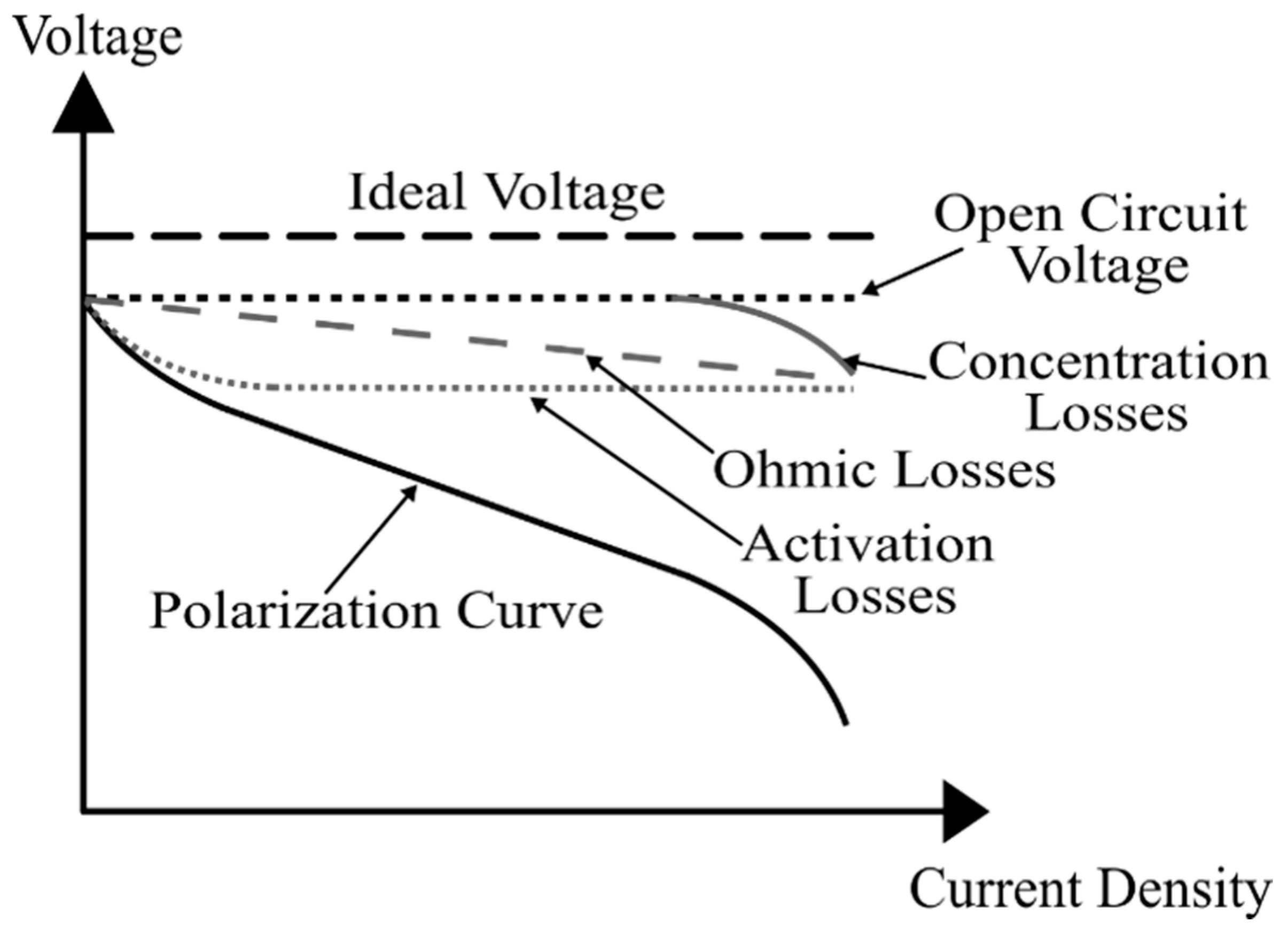
Figure 2 illustrates the electrical characteristic curve of a PEMFC, which exhibits a nonlinear current-voltage relationship [38]. This nonlinearity is primarily governed by three distinct voltage loss mechanisms: (1) activation losses due to electrochemical reaction kinetics, (2) ohmic losses arising from ionic and electrical resistances, and (3) concentration losses caused by mass transport limitations. Accounting for these losses, the terminal voltage (Vfc) of a PEMFC can be expressed as follows (3):
V f c = E V a c t , c e l l V o h m , c e l l V c o n c , c e l l
where E represents the open-circuit voltage of the FC, while Vact,cell, Vohm,cell, and Vconc,cell denote the activation, ohmic, and concentration overpotentials, respectively.
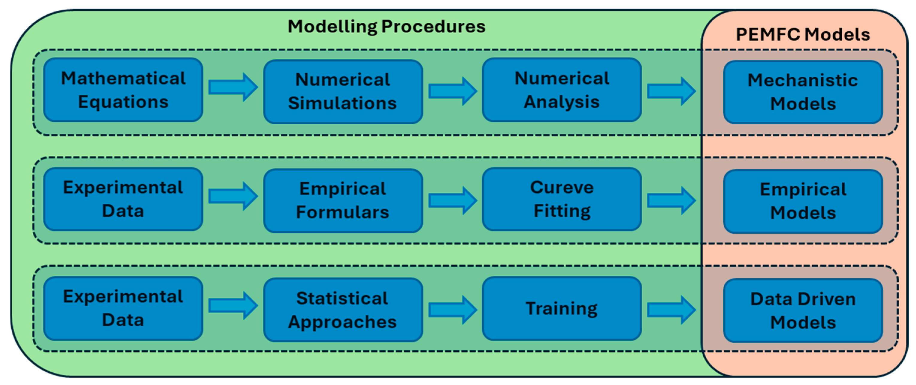
A wide range of PEMFC models has been developed to represent the loss mechanisms defined in (3) and to capture system behaviour under varying operating conditions. Over the past three decades, research efforts in PEMFC modelling have grown significantly, yielding numerous models in the literature. Broadly, these models can be categorized into three groups: (1) mechanistic models, (2) data-driven models, and (3) empirical models, as shown in Figure 3.

2.1. Mechanistic Models

Mechanistic models describe the internal physicochemical processes occurring within a PEMFC based on fundamental physical and electrochemical principles [39,40,41]. These models are formulated based on conservation laws of mass, momentum, energy, and charge [42], and typically incorporate electrochemical kinetics, fluid dynamics, and heat transfer to simulate coupled transport and reaction processes [43,44].
By explicitly capturing electrochemical reactions and energy transformations, mechanistic models enable detailed evaluation of performance metrics such as cell voltage, power density, and efficiency under varying operating conditions. This supports optimization of stack design, operating strategies, and material selection [45]. In addition, mechanistic simulations can assess electrode and electrolyte properties—including conductivity, catalytic activity, and stability—and help identify potential degradation and failure mechanisms [46,47]. Consequently, mechanistic models form an important theoretical basis for PEMFC design, optimization, and control, as well as for fault-tolerant and thermal management strategies.
Mechanistic modelling approaches often focus on one or more physical domains:
  • Electrochemical Models capture: Reaction kinetics and charge transfer processes at the electrodes using the Nernst equation for equilibrium potential, the Tafel equation for activation overpotential, and the Nernst–Planck formulation for ionic transport [42,48].
  • Thermodynamic Models: Analyse energy balance and heat generation mechanisms, providing insight into efficiency variations under different temperatures, pressures, and reactant conditions. Recent studies also highlight that effective thermal management strategies, such as liquid-cooled PEMFC systems, play a critical role in maintaining temperature uniformity, improving stack durability, and stabilizing electrochemical parameters during operation. They are particularly useful for thermal management design and optimization of operating parameters [44,49].
  • Fluid Dynamics Models: Simulate the flow and distribution of reactant gases (hydrogen and oxygen) and water within the flow channels and porous media. These models employ Navier–Stokes and continuity equations to investigate gas transport, pressure drop, and water management, all of which are crucial for maintaining stable operation and preventing flooding or membrane dehydration [45].
Comprehensive mechanistic frameworks often couple these domains to capture Multiphysics interactions (heat–mass–charge transport with electrochemical kinetics). Based on spatial resolution and computational complexity, mechanistic models are commonly categorized as zero-dimensional (0D), one-dimensional (1D), two-dimensional (2D), and three-dimensional (3D), each offering a trade-off between fidelity, interpretability, and computational cost [50]. A comparative summary of these mechanistic modelling approaches, including their key features, advantages, and limitations, is provided in Table 3.

2.1.1. Zero-Dimensional (0D) Models

Zero-dimensional or lumped-parameter models describe the overall behaviour of the PEMFC using averaged parameters and global conservation equations without spatial discretization [51,52]. These models represent the cell as a single control volume, typically expressed through algebraic or low-order differential equations. Despite their simplicity, 0D models are capable of predicting key global performance characteristics such as polarization curves, overall efficiency, and thermal response [53]. Due to their computational efficiency, they are widely used in system-level simulations, control design, and hybrid energy management studies, where detailed spatial information is not essential.

2.1.2. One-Dimensional (1D) Models

One-dimensional models provide a more detailed description by resolving variations along the through-plane direction—typically from the anode gas diffusion layer (GDL) to the cathode GDL—while assuming uniform conditions in the other two dimensions. The pioneering 1D model by Bernardi and Verbrugge described gas transport and electrochemical reactions across the membrane–electrode assembly (MEA) using coupled equations for species diffusion, charge conservation, and heat balance [54]. Later, Amphlett et al. [43] incorporated the Stefan–Maxwell equations to describe mass transfer, the Nernst–Planck equation to characterize ionic conduction, and the Tafel equation to model activation losses. Further enhancements by Mann et al. [44] extended the framework to generalized steady-state operation under various operating pressures and temperatures.
While 1D models offer good predictive accuracy for through-plane transport processes and are suitable for design and optimization of MEA materials, they neglect in-plane gradients, making them less effective for analysing local nonuniformities in gas distribution, temperature, or humidity.

2.1.3. Two-Dimensional (2D) Models

Two-dimensional models expand upon 1D formulations by accounting for variations both through the membrane and along the gas flow direction [55]. This enables the simultaneous evaluation of reactant distribution, temperature gradients, and liquid water accumulation within the flow channels and porous media. Early two-dimensional steady-state PEMFC models incorporated coupled gas diffusion, electrochemical reaction kinetics, and heat transfer across the flow channels and electrode layers [56]. Subsequent developments introduced more detailed mass and energy transport formulations, improving the accuracy of thermal and species distribution predictions [57]. Further advancements extended these frameworks to two-phase two-dimensional models, enabling the investigation of anisotropic transport properties, liquid water effects, and temperature distribution under varying current densities [58]. Although computationally more demanding than one-dimensional approaches, two-dimensional models provide a more realistic representation of fuel cell behaviour, particularly for performance prediction and flow-field design optimization.

2.1.4. Three-Dimensional (3D) Models

Three-dimensional models provide the most comprehensive and physically accurate representation of PEMFC operation by resolving transport and reaction processes in all spatial directions [59]. They couple electrochemical kinetics, mass and heat transfer, and fluid flow using computational fluid dynamics (CFD) and finite element (FEM/FVM) techniques [60]. Recent 3D Multiphysics models (e.g., Berning et al. [61]) have been employed to analyse water generation, thermal management, and mechanical compression effects in full-scale PEMFCs. These models can accurately capture local phenomena such as gas starvation, membrane dehydration, and liquid water flooding, which are difficult to analyse using lower-dimensional approaches.
However, their high computational cost and the need for extensive physical parameters make them impractical for real-time control or embedded applications. They are primarily used for fundamental research, material development, and system design optimization, where detailed spatial information is essential.

2.2. Data-Driven Models

Data-driven models predict the behaviour of PEMFCs by directly learning relationships between system inputs and outputs using empirical data, rather than solving detailed physicochemical equations [62,63,64,65]. Unlike mechanistic models that explicitly represent electrochemical and transport processes, data-driven frameworks infer system dynamics implicitly through statistical or machine-learning-based pattern recognition.
These models employ diverse algorithms, including artificial neural networks (ANNs), support vector regression (SVR), decision trees (DTs), random forests (RFs), Gaussian process regression (GPR), and deep learning (DL) architectures such as convolutional (CNN) and recurrent neural networks (RNNs), including long short-term memory (LSTM) and gated recurrent unit (GRU) variants [66]. These approaches have been successfully applied for performance prediction, fault detection, state-of-health (SOH) estimation, prognostics, and control-oriented modelling of PEMFCs [67].
Recent studies further demonstrate that data-driven and machine learning-based models are increasingly applied in PEMFC systems for performance prediction, degradation estimation, and real-time monitoring. Deep learning architectures, particularly RNN-based models such as LSTM and GRU, have shown strong capability in capturing transient voltage behaviour and degradation trends under dynamic operating conditions. For example, GRU-based frameworks have achieved high prediction accuracy with reduced computational complexity, making them suitable for online degradation prediction [66]. In addition, data-driven models based on operational variables have been successfully used to predict PEMFC power output and support real-time monitoring and energy management applications.
For instance, Zhang et al. developed an LSTM-based framework to predict dynamic voltage response under variable load conditions, accurately capturing nonlinear transients and hysteresis effects [68]. Similarly, Liu et al. demonstrated the use of Bayesian-optimized deep neural networks (DNNs) for transient voltage prediction, achieving reduced mean-absolute-error and enhanced robustness to measurement uncertainty [69].
Beyond conventional supervised learning, unsupervised and reinforcement learning (RL) paradigms have been introduced for anomaly detection and adaptive control. Clustering algorithms such as k-means, self-organizing maps (SOMs), and autoencoders identify degradation patterns in sensor data, while RL-based controllers autonomously optimize operational parameters to enhance durability and efficiency [68,70].
Although these methods exhibit high computational efficiency during inference, their predictive accuracy depends strongly on the quality, representativeness, and volume of training data. Overfitting, data imbalance, and sensor noise can compromise model generalization. Moreover, most data-driven architectures behave as “black boxes,” limiting interpretability and trustworthiness when extrapolated beyond trained domains [71].
To address these shortcomings, recent studies focus on hybrid and physics-informed modelling frameworks that integrate mechanistic knowledge into data-driven architectures. Physics-informed neural networks (PINNs) and Gray-box hybrid models embed physical constraints (e.g., mass- or charge-balance equations) into the learning process, preserving interpretability while maintaining computational speed [72]. For example, coupling a reduced-order electrochemical model with an LSTM surrogate allows accurate transient prediction with a fraction of the computational cost [73].
Additionally, digital-twin platforms—which synchronize real-time operational data with continuously updated ML models—are emerging for online monitoring, predictive maintenance, and control optimization of PEMFC systems [74,75]. These frameworks dynamically recalibrate model parameters from sensor feedback, offering a pathway toward self-adaptive and resilient FC operation.
Despite these advantages, data-driven approaches rely heavily on the availability of large, high-quality datasets and often operate as black-box models, limiting interpretability and robustness when extrapolated beyond trained conditions. A comparative summary of commonly used data-driven modelling techniques is provided in Table 4. This highlights the need for hybrid or simplified modelling approaches that can maintain both accuracy and practical applicability.

2.3. Empirical Models

Empirical models are derived from experimental data fitted to simplified mathematical representations of PEMFC behaviour. Unlike mechanistic or data-driven models, empirical approaches utilize limited experimental data to develop computationally efficient, reduced-order models. Their accuracy is inherently constrained by the quality and operating range of the experimental data used for calibration [71]. Consequently, empirical models may exhibit reduced reliability when applied outside their original validation conditions.
Among the various PEMFC modelling approaches, empirical models have found extensive application in electrical engineering and power electronics domains due to their ability to represent fundamental FC characteristics using basic electrical components. In practical power electronic systems, PEMFCs are commonly interfaced with DC–DC converters, inverters, and hybrid energy storage systems, exposing them to operating conditions such as high-frequency current ripple, pulsed current excitation, and rapid load transients. As a result, the suitability of an empirical PEMFC model is largely determined by its capability to capture the dynamic voltage response of the FC under electrically induced disturbances, in addition to steady-state behaviour.
Empirical PEMFC models typically employ resistive, capacitive, and semiconductor-based elements to approximate activation losses, ohmic losses, concentration polarization, and transient voltage dynamics. Based on their structure and level of abstraction, four primary categories of empirical models have been reported in the literature for electrical and power electronics applications: (1) electronic circuit-based models, (2) frequency response equivalent circuit models, (3) original electric equivalent circuit models, and (4) simplified equivalent circuit models. A comparative summary of these model types is provided in Table 5, and their applications, advantages and limitations are provided in Table 6. While all four model categories aim to replicate the electrical behaviour of PEMFCs, they differ significantly in modelling complexity, physical relevance, and applicability to power electronics studies.

2.3.1. Electronic Circuit-Based Models

Electronic circuit-based models emulate PEMFC behaviour using conventional circuit elements such as resistors, capacitors, diodes, and controlled sources [88]. These models are particularly well suited for system-level simulations and converter-interfaced studies, as they can directly represent voltage fluctuations arising from current ripple and pulsed loading imposed by switching power converters. Their moderate accuracy and compatibility with simulation platforms such as MATLAB/Simulink R2022b, PSPICE, and PSIM make them attractive for control and power management investigations.

2.3.2. Frequency Response Equivalent Circuit Models (FRECMs)

FRECMs are derived from electrochemical impedance spectroscopy (EIS) data and characterize the dynamic behaviour of PEMFCs over a range of frequencies [89]. By fitting impedance spectra with networks of resistors, capacitors, inductors, and constant phase elements, FRECMs provide valuable insight into frequency-dependent processes such as charge transfer dynamics, double-layer capacitance, and mass transport effects. These models are particularly effective for analysing converter–FC interactions and current ripple effects within specific frequency bands, although their parameter identification is computationally intensive and often valid only for limited operating conditions.

2.3.3. Original Electric Equivalent Circuit Models

Original electric equivalent circuit models establish direct analogies between electrochemical phenomena and electrical components, enabling the representation of activation kinetics, membrane proton transport, and diffusion processes through physically motivated circuit elements [90]. While these models offer enhanced physical fidelity and are useful for examining the impact of transient current excitation on internal FC processes, their high complexity and extensive parameter requirements limit their suitability for large-scale power electronics simulations and iterative converter design studies.

2.3.4. Simplified Equivalent Circuit Model

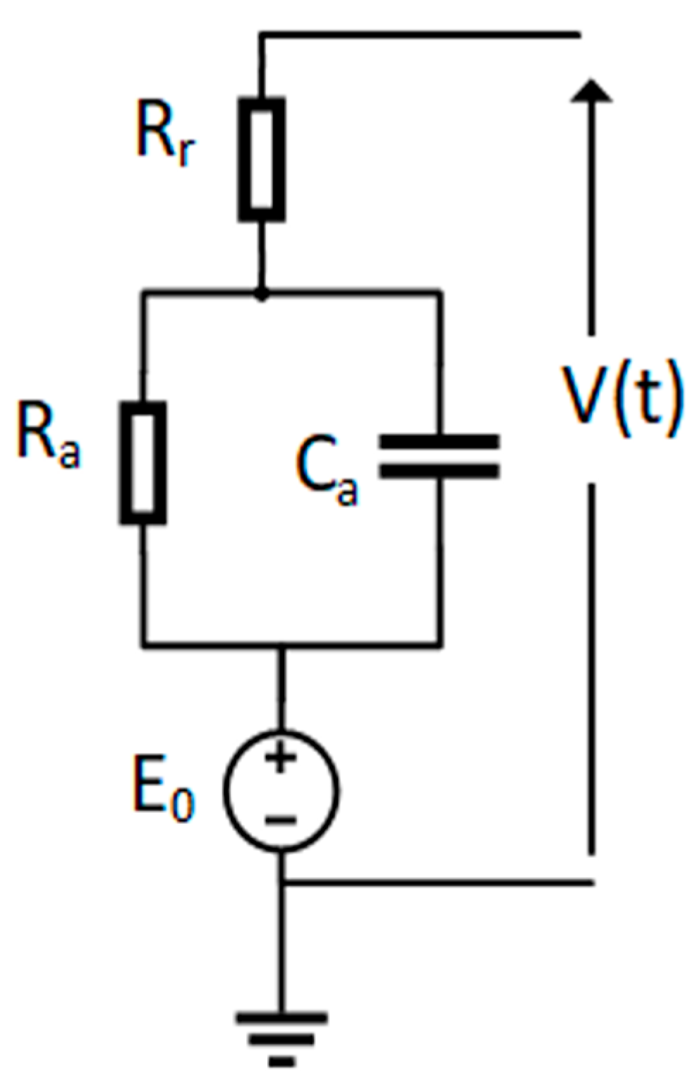
Simplified equivalent circuit models provide reduced-order representations that capture the dominant steady-state and transient characteristics of PEMFCs using a minimal set of circuit elements [91]. Typically consisting of an ideal voltage source in series with a resistance and a parallel RC network, these models are computationally efficient and well suited for control design, real-time simulation, and system-level analysis in power electronics applications. Although simplified models do not accurately represent high-frequency electrochemical phenomena, they offer an effective compromise between modelling fidelity and computational efficiency when evaluating converter-induced current ripple, pulsed loading, and energy management strategies.
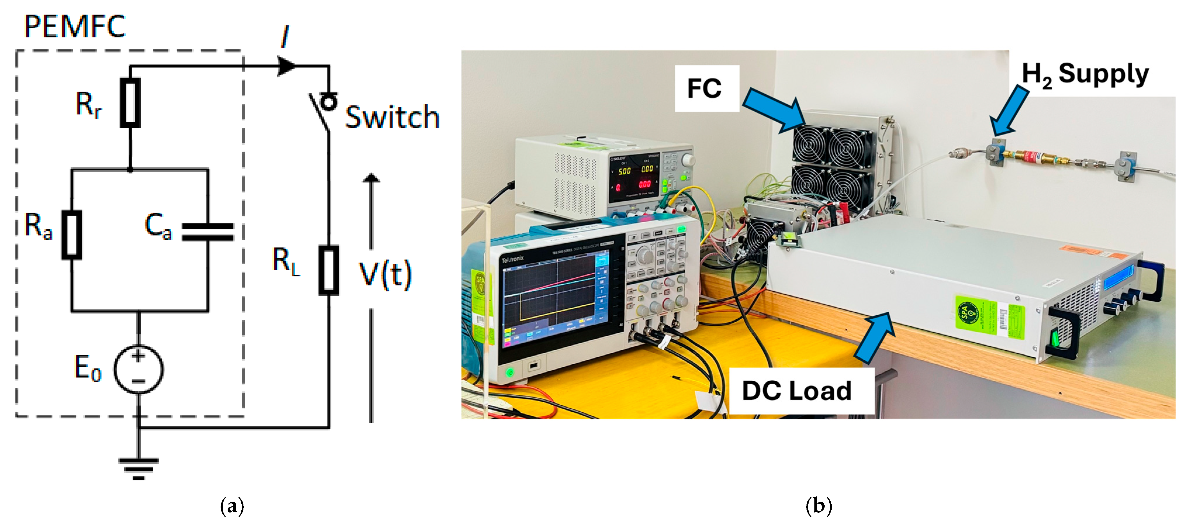
As schematically represented in Figure 4, this model topology incorporates: an ideal voltage source (E) represents the open circuit voltage of the PEMFC, a series resistance (Rr) represents the internal resistance of the FC and a parallel RC branch (Ra and Ca) models the charge transfer resistance and capacitive effects of the FC. Under steady-state operation, the capacitor Ca becomes fully charged, causing all current to flow through Ra. However, during transient load changes, Ca introduces a delay in the terminal voltage response of the FC.
While this model effectively emulates the electrical behaviour of PEMFCs, its accuracy is highly dependent on the precision of the equivalent circuit parameters. Therefore, accurate parameter identification is critical for reliable model performance.
Recent research has increasingly focused on improving the applicability of empirical equivalent circuit models for real-time and control-oriented applications. In particular, advanced parameter estimation techniques based on optimization algorithms and real-time identification methods have been proposed to enhance model accuracy under dynamic operating conditions. Recent work in PEMFC parameter estimation using optimization methods demonstrates that improved parameter identification can significantly enhance model robustness and predictive accuracy across different operating scenarios [92].
Furthermore, the study by Mei et al. (2024) [93] highlights the importance of accurate voltage model parameter extraction for improving real-time performance and reliability of PEMFC systems.
In summary, while mechanistic and data-driven models provide valuable insights into PEMFC behaviour, their practical implementation in parameter estimation and real-time control applications remains limited. Mechanistic models, although physically accurate, involve complex Multiphysics formulations and require extensive computational resources, making them unsuitable for real-time applications and online parameter identification. Data-driven approaches, while computationally efficient during inference, rely heavily on large datasets and often lack interpretability and robustness under varying operating conditions and degradation.
In contrast, empirical equivalent circuit models simplify PEMFC behaviour into electrically interpretable components, enabling direct correlation between measurable voltage–current responses and model parameters. This reduced-order representation significantly lowers computational complexity while preserving the dominant dynamic characteristics of the system. As a result, empirical models—particularly simplified equivalent circuit models—are highly suitable for real-time applications and parameter estimation. Their parameters can be extracted using transient voltage responses obtained from controlled current perturbations, without requiring complex optimization procedures or large datasets.
Therefore, empirical modelling provides a practical and effective framework for parameter estimation, which motivates the use of current-switching-based techniques in this work. The detailed experimental procedure and parameter calculation methodology are presented in Section 3.

3. Current Switching Techniques for PEMFC Parameter Estimation

Accurate parameter identification is a crucial step in developing reliable simplified equivalent circuit models of PEMFCs. The model parameters—such as internal resistance, charge transfer resistance, and double-layer capacitance—directly influence the fidelity of the simulated dynamic and steady-state behaviour. Traditional parameter estimation approaches often rely on steady-state polarization curves or frequency response analysis; however, these methods can be time-consuming, require specialized equipment, and may not effectively capture transient characteristics under realistic operating conditions.
To address these limitations, current switching techniques have emerged as an efficient and practical approach for PEMFC parameter estimation. In this method, the FC is subjected to controlled current perturbations or step changes, and the corresponding transient voltage response is analysed. The dynamic voltage behaviour obtained from these tests provides valuable insight into the electrochemical and electrical dynamics of the PEMFC, enabling accurate extraction of equivalent circuit parameters.
Two primary tests can be classified under the current switching technique:
  • Current Loading Technique
  • Current Interrupting Technique
Figure 4 illustrates the block diagram of the experimental setup used to perform these tests. In each test, the voltage response of the FC is recorded following a current transition, and the parameters of the simplified equivalent circuit model are subsequently determined based on the observed transient behaviour.

3.1. Current Loading Technique

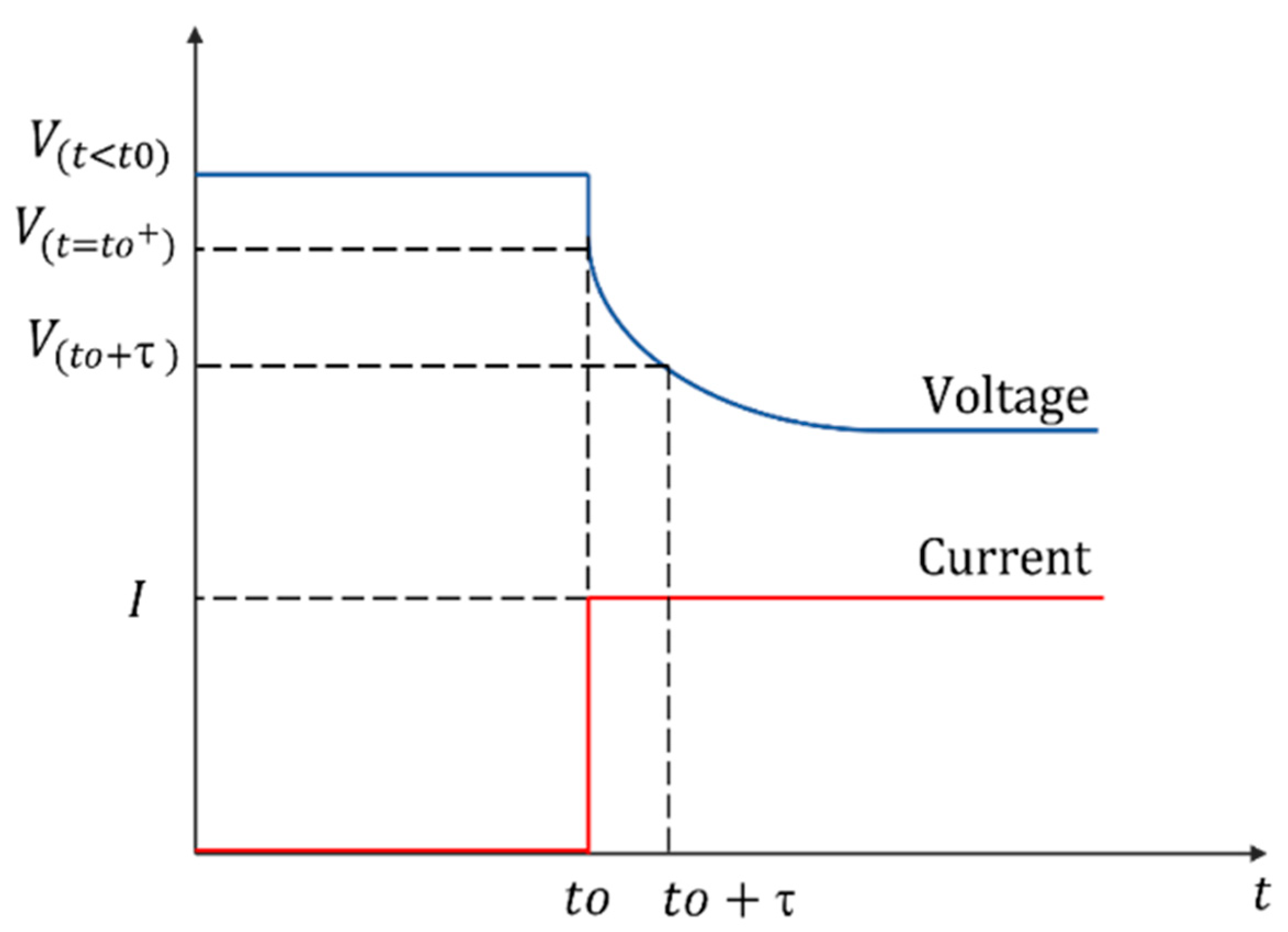
In the current loading test, the PEMFC initially operates under open-circuit conditions. Once a steady-state voltage is achieved, a constant current load is suddenly applied to the system. This abrupt change in load current induces a transient response in the terminal voltage, reflecting the internal electrochemical and capacitive dynamics of the FC. Figure 5 depicts the typical terminal voltage response of the PEMFC during the current loading test. The different stages of this voltage profile, including the instantaneous voltage drop, transient recovery, and steady-state stabilization, can be mathematically characterized using the simplified PEMFC equivalent circuit.
The PEMFC steady-state voltage under open-circuit conditions can be expressed as follows:
E 0 = V t < t 0
Following the sudden application of a constant load, the transient terminal voltage response of the PEMFC can be formulated as:
V ( t ) = R L R L + R a + R r 1 e t t 0 τ E 0 + R L R L + R r   e t t 0 τ E 0
Here, τ denotes the time constant of the equivalent circuit, which is determined as:
τ = C a ( R a R L + R a R r ) R L + R a + R r
The load resistance (RL) can be calculated using the steady-state voltage and current as (7):
R L = V S S I
As illustrated in Figure 5, when the load is abruptly connected to the PEMFC at t = t0, the initial voltage drop can be expressed as:
V ( t = t 0 + ) = R L R L + R r   E 0
During steady-state operation, Ca becomes fully charged, and the current flows entirely through the Ra. The corresponding terminal voltage is defined as:
V S S = R L R L + R r + R a   E 0
From the PEMFC terminal voltage profile obtained during the current loading test, the quantities Vss, V(t=t0), V(t<t0), and τ can be extracted. These values are then used to determine the parameters of the simplified PEMFC equivalent circuit as follows.
The open-circuit voltage (E0) is obtained directly from:
E 0 = V t < t 0
The internal resistance (Rr) is determined by combining (8) and (10), as shown in (11):
R r = V ( t < t 0 ) V ( t = t 0 + )   R L R L
The charge transfer resistance (Ra) is subsequently calculated using (9) and (11):
R a = R L E 0 V S S   R L R r
Finally, the double-layer capacitance (Ca) is obtained from (6), (11) and (12):
C a = τ   ( R L + R a + R r ) R a ( R L + R r )

3.2. Current Interruption Technique

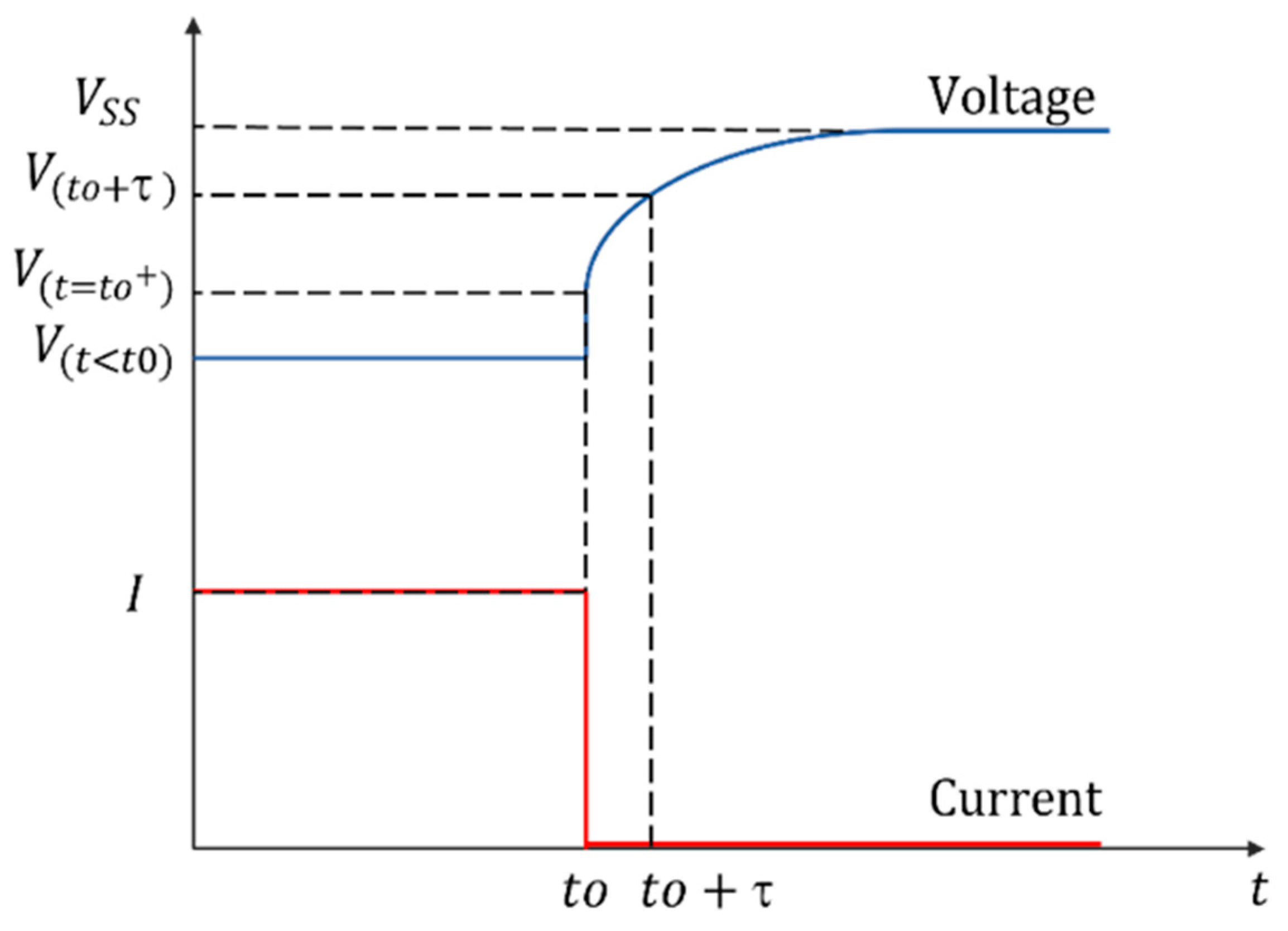
In the current interruption test, the PEMFC is initially operated under a constant current load. Once steady-state conditions are achieved, the load is abruptly disconnected while recording the corresponding transient voltage response. Figure 6 illustrates the typical voltage profile observed during this test. Each stage of the voltage response can be mathematically described using the simplified PEMFC equivalent circuit model.
During steady-state operation prior to interruption, Ca in the equivalent circuit is fully charged, resulting in zero current flow through the capacitive branch. The terminal voltage at this stage can be expressed as:
V ( t < t 0 ) = E 0 I R a + R r = I R L
where I represent the steady-state current prior to load disconnection. The load resistance (RL) can thus be determined as:
R L = V ( t < t 0 ) I
After the load is disconnected at t = t0, the transient voltage response of the PEMFC is characterized by:
V ( t ) = E 0 I R a e t t 0 τ
Here τ denotes the time constant of the equivalent circuit following the current interruption, defined as:
τ = R a C a
Immediately after the load disconnection, the terminal voltage can be expressed using (16) as:
V ( t = t 0 + ) = E 0 I R a
The open-circuit voltage (E0) of the PEMFC is then obtained from the final steady-state voltage:
E 0 = V S S
These equations enable the determination of the key parameters of the simplified equivalent circuit. The internal resistance Rr is calculated by combining (14) and (18):
R r = V ( t = t 0 + ) V ( t < t 0 ) I
The charge transfer resistance Ra is determined from (18) and (19):
R a = V S S V ( t = t 0 + ) I
Finally, using the time constant τ derived from the transient voltage response, the double-layer capacitance (Ca) can be calculated as:
C a = τ R a

4. Experimental Procedure

The proposed parameter estimation techniques were experimentally validated using a laboratory test setup, as illustrated in Figure 7. The setup consists of Horizon FC Technologies (Nagpur, India)’ H-100 (100 W) and H-1000 (1 kW) PEM FC stacks, a regulated hydrogen supply system, a controllable DC electronic load, and a digital oscilloscope for data acquisition.
The technical specifications of the H-100 and H-1000 PEMFC stacks are summarized in Table 7. To ensure experimental reproducibility and consistency in parameter extraction, the PEMFC stacks were operated under controlled conditions throughout all tests. As summarized in Table 7, both the 100 W and 1 kW systems were supplied with hydrogen at a pressure of 0.45–0.55 bar and a purity of at least 99.995% dry H2, while stack cooling was provided by integrated cooling fans. The maximum stack operating temperature was maintained at 65 °C in accordance with the manufacturer specifications, and the external auxiliary power supply was regulated at 13 V (±1 V). All experiments were conducted at an ambient laboratory temperature of approximately 22–25 °C with a typical relative humidity of approximately 50–65%.
During all experiments, the electronic load was operated in constant-current mode so that the imposed current steps were well defined and repeatable. Maintaining these operating conditions was important because variations in temperature, gas pressure, fuel quality, and load stability can influence the transient voltage response of the PEMFC and therefore affect the accuracy of the extracted equivalent circuit parameters.
No active humidity control was externally imposed beyond the manufacturer-configured stack operating arrangement; therefore, the reported results correspond to the nominal operating conditions of the commercial PEMFC systems used in this study. The test parameters and conditions corresponding to each experiment are presented in Table 8.
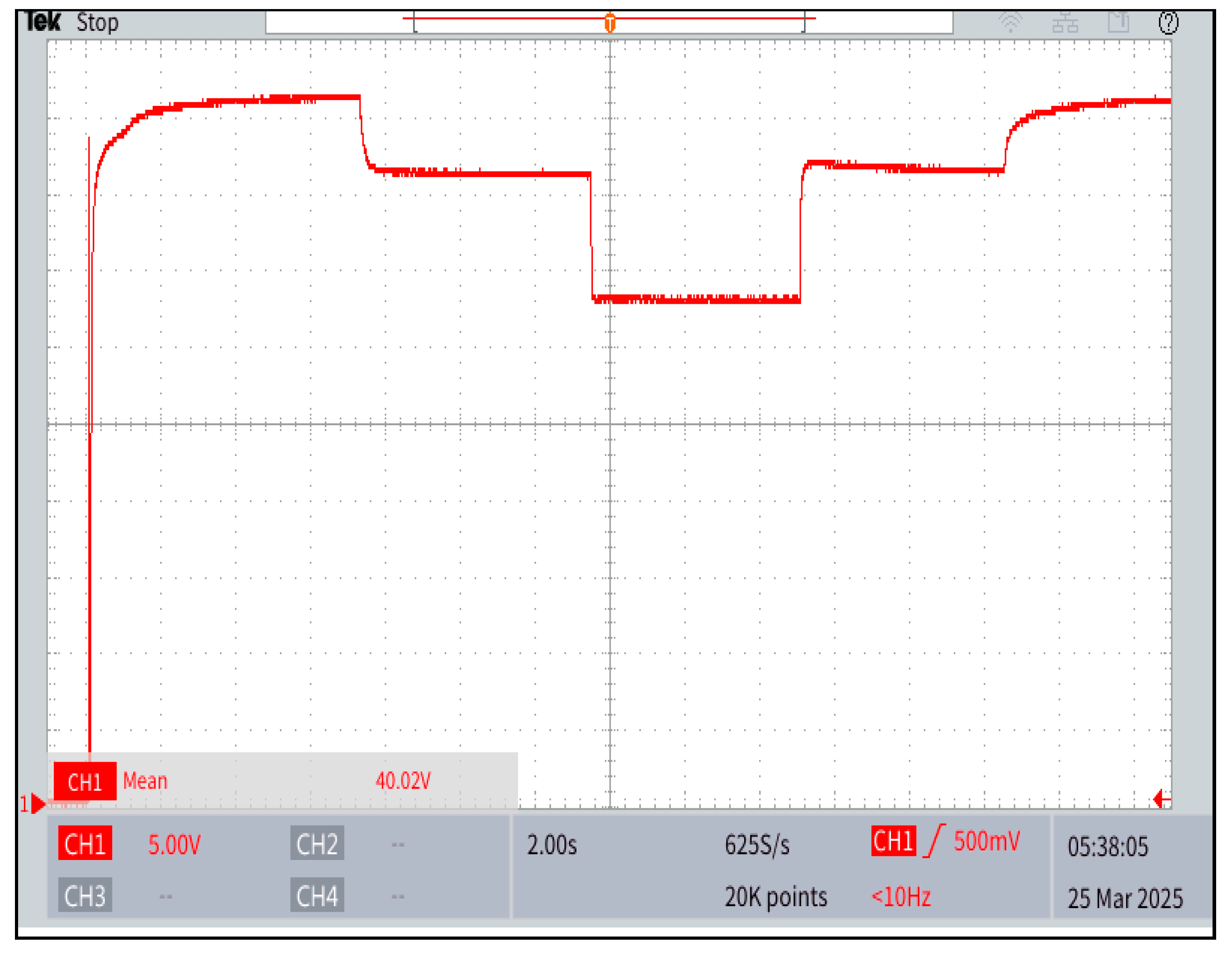
As shown in Figure 8, For each test scenario, the terminal voltage profiles of the PEMFC were recorded during both current loading and current interruption operations. The measured transient voltage responses were then analysed to calculate the equivalent circuit parameters based on the equations derived in Section 3. These experimentally obtained results were compared with theoretical model responses to verify the accuracy and validity of the proposed parameter estimation methodology.

4.1. Current Loading Test

In the current loading test, the equivalent circuit parameters were calculated using Equations (7), (8) and (11). Table 9 presents the equivalent circuit parameters obtained from each current loading test for the 100 W and 1 kW PEMFCs.
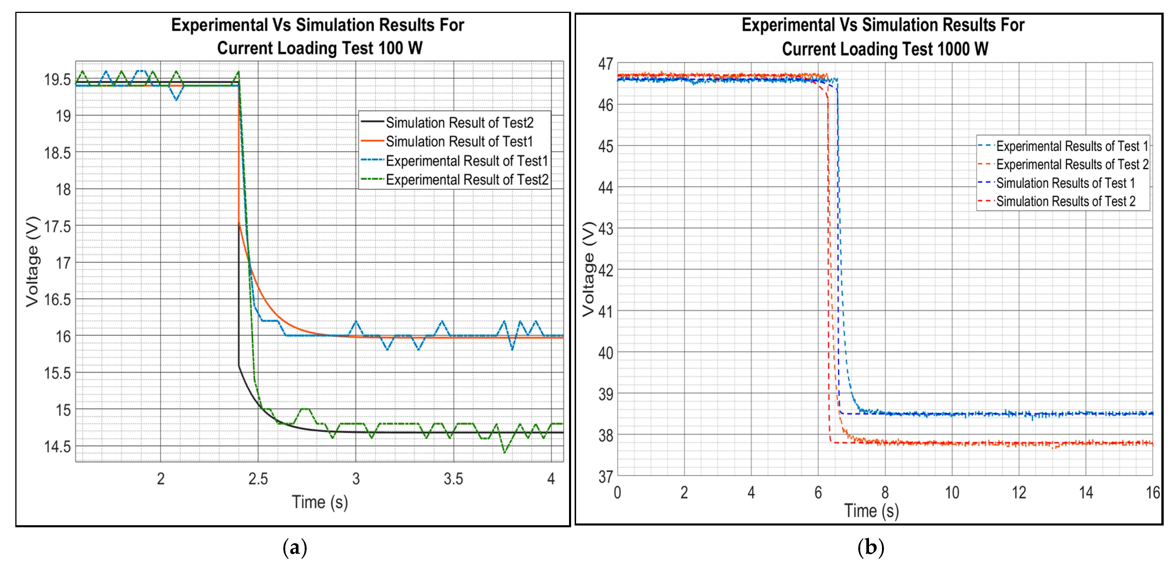
The measured and simulated voltage responses corresponding to the current loading test are shown in Figure 9 for the 100 W and 1 kW FCs, respectively. The simulated curves closely follow the experimental results, confirming that the simplified equivalent circuit accurately represents the PEMFC’s dynamic response under step current loading conditions.

4.2. Current Interruption Test

In the current interruption test, the equivalent circuit parameters were determined using Equations (18), (19) and (22). Table 10 presents the equivalent circuit parameters obtained from each current interruption test for the 100 W and 1 kW PEMFCs.
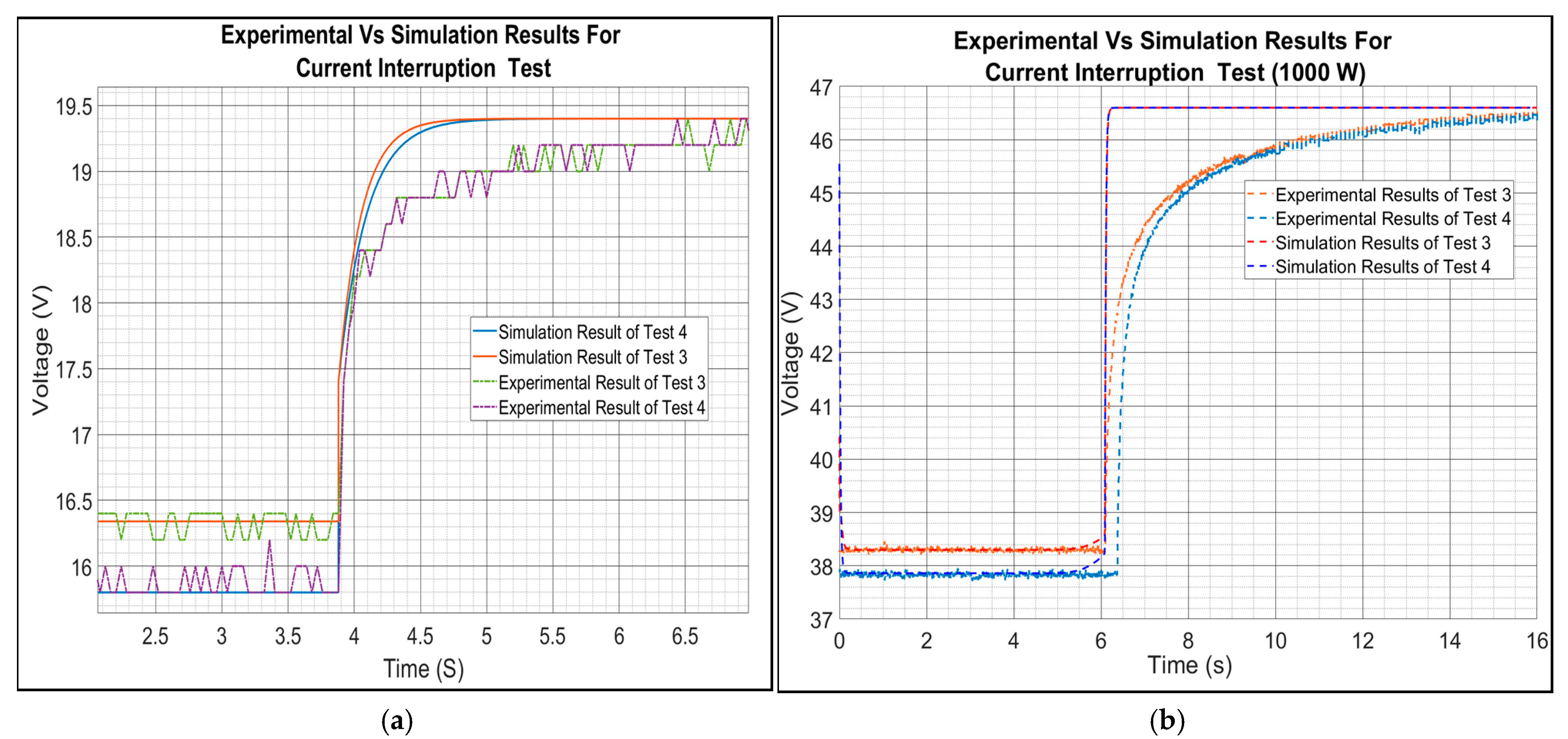
The corresponding measured and simulated transient voltage profiles for the 100 W and 1 kW PEMFCs are illustrated in Figure 10, respectively. The close alignment between the experimental and simulated voltage responses demonstrates that the proposed equivalent circuit effectively captures the transient behaviour of the PEMFC following current interruption.
Table 11 summarizes the maximum error observed between the PEMFC responses and the simplified equivalent circuit predictions under each test condition. As shown, the maximum error remains below 10%, confirming the reliability and accuracy of the proposed method for determining the equivalent circuit parameters of the simplified equivalent circuit model.
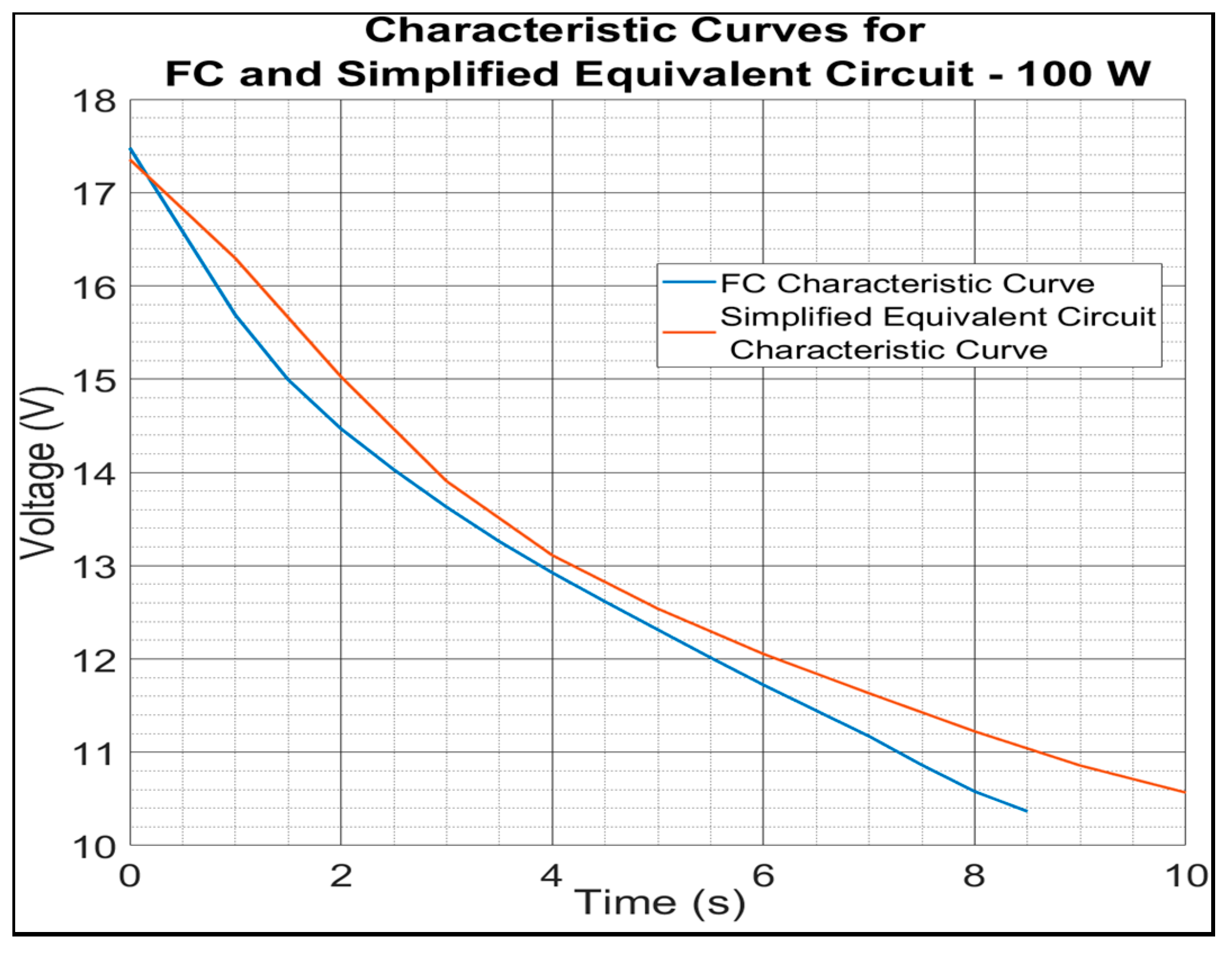
Additionally, to further validate the accuracy of the derived model, the characteristic voltage–current (V–I) curves of the actual PEMFCs (obtained from manufacturer datasheets) were compared with those generated from the equivalent circuit model. Figure 11 depicts these comparisons for the 100 W and 1 kW PEMFCs, respectively. As shown, the characteristic curves derived from the equivalent circuit are nearly identical to the actual PEMFC curves, thereby confirming the validity and accuracy of the model and the computed equivalent circuit parameters.

5. Evaluation and Implementation Potential

A variety of PEMFC equivalent circuit models have been proposed by researchers to capture the electrical and dynamic characteristics of FCs, depending on the intended application. Within the broader PEMFC modelling framework presented in Section 2, the proposed approach belongs to the category of empirical equivalent circuit models but introduces a practical parameter identification strategy specifically tailored for electrical engineering applications. In the context of electrical engineering, the use of a simplified equivalent circuit model provides an effective means to represent the behaviour of a PEMFC using only basic circuit elements—resistors and capacitors. This approach enables accurate replication of both steady-state and transient responses, without requiring detailed consideration of the complex electrochemical processes occurring within the FC.
Compared with mechanistic models, which typically require the numerical solution of coupled nonlinear partial differential equations describing mass transport, electrochemical kinetics, and thermal dynamics, the proposed simplified modelling framework significantly reduces computational complexity. Data-driven models also require large datasets and computationally intensive training procedures. In contrast, the proposed method determines model parameters directly from experimentally measured transient voltage responses using current-switching tests. As a result, the approach provides a balance between modelling accuracy, computational efficiency, and practical applicability for system-level studies.
To quantify the computational advantages of the proposed modelling framework, a comparison of modelling complexity and computational requirements between commonly used PEMFC modelling approaches is presented in Table 11. Mechanistic models typically require the numerical solution of coupled nonlinear partial differential equations representing mass transport, electrochemical kinetics, and thermal dynamics, often involving tens of physical parameters and high computational cost. Data-driven models also require large datasets and computationally intensive training procedures. In contrast, the proposed simplified equivalent circuit model represents the PEMFC using only three key parameters (Rr, Ra, and Ca) and can be evaluated using simple algebraic expressions derived from transient voltage responses. As a result, the proposed method significantly reduces computational complexity and enables simulation and parameter estimation within milliseconds, making it particularly suitable for real-time control, digital twin implementation, and power electronics applications.
Such models are particularly advantageous for system-level analyses, including integration studies of FCs in DC microgrids, hybrid power systems, and power electronic interfaces, where electrical engineers primarily focus on dynamic response, stability, and control aspects rather than electrochemical kinetics. However, the accuracy of any equivalent circuit model strongly depends on the precision of the identified parameters. Therefore, reliable and repeatable parameter extraction techniques are essential for ensuring that the simplified model faithfully represents real-world PEMFC performance.
In this study, current switching techniques—specifically the current loading and current interruption methods—were utilized to determine the equivalent circuit parameters of 100 W and 1 kW commercial PEMFC stacks. The results presented in the previous section demonstrate that parameters obtained from these methods enable the simplified equivalent circuits to accurately reproduce both the dynamic and steady-state characteristics of the FCs. As shown in Table 12, the maximum error remains below 10% across all test cases, with several cases exhibiting significantly lower error levels (e.g., ~1.4–3%), confirming good agreement between experimental and modelled results. The observed modelling error can arise from several sources. First, measurement noise and sampling limitations in the voltage acquisition system may introduce small uncertainties when capturing the transient voltage response, particularly during rapid voltage transitions immediately following current switching events. Second, the simplified equivalent circuit model inherently represents complex electrochemical processes using lumped parameters, which can introduce approximation errors, particularly under highly nonlinear operating conditions. For example, concentration losses and spatial effects within the fuel cell are not explicitly modelled, which may contribute to discrepancies at higher current densities. In addition, variations in operating conditions such as temperature, hydrogen pressure, and membrane hydration can influence internal resistances and dynamic behaviour, potentially leading to parameter estimation deviations. These limitations represent the typical trade-off between modelling simplicity and physical accuracy in reduced-order models. Future improvements may include incorporating adaptive parameter updating strategies, additional nonlinear elements to better represent concentration effects, and enhanced filtering techniques to reduce measurement noise during transient detection. The excellent agreement between the simulated and measured voltage profiles, as well as the close match between the modelled and datasheet characteristic curves, further validates the reliability of these techniques.
The accuracy and robustness of the proposed parameter estimation approach can also be evaluated in the context of recent polarization loss decomposition techniques reported in the literature. For example, the method presented in [96] employs a systematic decomposition of activation, ohmic, and concentration losses using electrochemical measurements such as Tafel analysis and high-frequency resistance, achieving voltage prediction errors below 1% across the full operating range. In comparison, the proposed simplified equivalent circuit model adopts a reduced-order representation, where polarization losses are incorporated into lumped parameters, particularly through the concept of equivalent resistance. Despite this simplification, the proposed method achieves a comparable level of predictive accuracy while significantly reducing computational complexity and measurement requirements. This highlights that, although detailed electrochemical decomposition approaches provide higher physical interpretability, simplified models combined with appropriate parameter estimation techniques can achieve similar performance for system-level applications. Furthermore, polarization loss decomposition techniques provide a pathway for enhanced health state monitoring by enabling quantification of degradation-related parameters such as electrochemical surface area (ECSA) and equivalent resistance. In this context, for degradation-aware recalibration, such techniques can provide quantifiable ageing indicators, which can be integrated with the proposed modelling framework to support advanced applications such as digital twins and predictive maintenance in PEMFC systems.
Thermal effects also play an important role in the degradation and durability of PEMFC systems. Temperature variations influence electrochemical reaction kinetics, membrane hydration, catalyst activity, and internal resistances, which can directly affect the stability of equivalent circuit parameters over time. Recent studies have shown that temperature-dependent state-of-health (SOH) models can be used to systematically quantify the sensitivity of PEMFC degradation mechanisms to thermal operating conditions. For example, adaptive SOH temperature sensitivity analysis has been proposed to evaluate the influence of temperature on PEMFC ageing behavior and to develop durability improvement strategies through dynamic parameter compensation. In this context, the simplified equivalent circuit model and the low-complexity parameter estimation method proposed in this work can complement such SOH-based approaches. By periodically estimating the equivalent circuit parameters under varying operating conditions, it becomes possible to track temperature-induced parameter drift and integrate these observations into adaptive health monitoring frameworks. This combination can enable real-time degradation monitoring and durability management for PEMFC systems used in dynamic environments such as microgrids, transportation systems, and hybrid energy storage applications.
The key advantages of the current switching techniques include their simplicity, low cost, and high repeatability. The required instrumentation is minimal—typically a programmable DC load and a voltage measurement device—making the method suitable for both laboratory testing and field implementation. Moreover, the technique does not require complex electrochemical impedance measurements or invasive system modifications, which enhances its applicability to commercial PEMFC systems.
The sensitivity of the parameter estimation methods to measurement noise differs between the current loading and current interruption techniques. The current interruption method relies on capturing an instantaneous voltage jump immediately after current disconnection to estimate resistive components, making it more sensitive to high-frequency measurement noise, sampling resolution, and switching transients. In contrast, the current loading method extracts parameters from the transient voltage evolution over a finite time window, allowing implicit averaging of noise and therefore offering improved robustness in practical implementations. However, the loading method may be more sensitive to slow measurement drift and load regulation accuracy. This trend is also reflected in the results, where the current loading method generally exhibits improved accuracy compared to the current interruption method, as illustrated in Figure 9 and Figure 10. Overall, the current loading technique is generally more robust to noise, whereas the current interruption method provides faster estimation but requires higher measurement fidelity and careful signal conditioning.

Real-Time Monitoring and Digital-Twin Application

As discussed, the simplified equivalent circuit parameters can be determined solely from the voltage response to a sudden change in load current. In practical FC applications, such transient conditions naturally occur during normal operation. For example, in vehicular systems, rapid load variations arise during acceleration or braking events, while in microgrid environments, they occur due to sudden demand fluctuations. These naturally occurring load transients are analogous to the controlled current switching conditions applied in this study.
Consequently, by capturing the voltage and current profiles during these regular operational events, it becomes possible to estimate the equivalent circuit parameters in real time without interrupting or perturbing the PEMFC’s normal function. This non-intrusive approach allows continuous model updating, enabling online monitoring and digital-twin-based applications aimed at maintaining an accurate, up-to-date representation of the PEMFC’s electrical behaviour.
The implementation of this real-time monitoring strategy requires only the integration of voltage and current sensing modules with data communication capabilities to stream measurements to a local controller or a cloud-based monitoring platform. Using the acquired voltage and current data, the simplified equivalent circuit parameters of the PEMFC can be computed based on the parameter extraction methodologies described earlier. The updated parameters can then be compared with previously identified values to track parameter drift, performance degradation, and the evolution of the state of health (SOH) under varying operating and environmental conditions, such as temperature, humidity, and pressure.
This approach offers a scalable and cost-effective pathway for in situ diagnostics, predictive maintenance, and adaptive control of PEMFC systems. By leveraging operational transients as natural excitation signals, the method eliminates the need for specialized test sequences and supports the development of self-updating digital twins, thereby enhancing the long-term reliability and efficiency of PEMFC-powered energy systems.
It should be noted that the simplified equivalent circuit model adopted in this study does not explicitly include elements to represent concentration losses. In PEMFCs, concentration losses become significant at high current densities due to mass transport limitations, leading to a nonlinear voltage drop in the high-current region of the polarization curve. In the proposed model, these effects are not separately parameterized but are implicitly captured within the lumped parameters, particularly the internal resistance and the equivalent RC network.
As a result, while the model demonstrates good accuracy under low to moderate current operating conditions, its ability to precisely reproduce the voltage behaviour at high current densities may be limited. This reflects the inherent trade-off of simplified models, where reduced complexity is achieved at the expense of detailed electrochemical representation. Nevertheless, for the intended applications of this work—such as control-oriented modelling, real-time parameter estimation, and system-level analysis—the dominant system dynamics are adequately captured.
Furthermore, the experimental validation in this study is limited to low- and medium-power PEMFC systems (100 W and 1 kW). The applicability of the proposed method to higher-power or multi-stack systems requires further investigation, as additional factors such as thermal gradients, stack non-uniformities, and balance-of-plant interactions may influence parameter estimation accuracy. Future work may focus on extending the model by incorporating additional nonlinear elements to explicitly account for concentration losses, particularly for operation near the limiting current region or under high-power transient conditions.

6. Conclusions and Future Directions

This paper presented a practical and computationally efficient methodology for parameter estimation of a simplified equivalent circuit model of proton exchange membrane fuel cells (PEMFCs) using current-switching techniques. The proposed approach enables accurate extraction of key model parameters, including internal resistance, charge transfer resistance, and double-layer capacitance, based on transient voltage responses under controlled current perturbations.
Experimental validation was conducted using 100 W and 1 kW PEMFC systems under both current loading and current interruption tests. The results demonstrated good agreement between measured and simulated responses, with a maximum error below 10% and several cases achieving significantly lower error levels, confirming the effectiveness of the proposed approach.
From an application perspective, the proposed method is particularly well suited for real-time and control-oriented implementations, including integration with power electronic converters, hybrid energy storage systems, and DC microgrids. Its low computational requirement and reliance solely on measurable electrical signals make it highly suitable for deployment in digital twin platforms, condition monitoring systems, and advanced energy management strategies in hydrogen-based power systems. This positions the proposed approach as a practical tool for supporting emerging hydrogen energy infrastructures, where reliable and scalable modelling is essential for system integration and operational optimisation.
Practical implementation of the proposed modelling approach in large-scale PEMFC systems may also present several engineering challenges. In real-world applications such as DC microgrids or hybrid energy systems, PEMFC stacks are typically interfaced with power electronic converters that introduce additional dynamic interactions, including switching ripple, control delays, and measurement latency. These factors may influence the accuracy and stability of real-time parameter estimation if not properly considered. In addition, scalability to higher-power multi-stack systems may introduce non-uniform operating conditions, thermal gradients, and balance-of-plant interactions that can affect parameter consistency across the stack.
The proposed current-switching-based parameter estimation technique is fundamentally based on analysing the transient voltage response of a fuel cell to controlled current perturbations. In principle, this methodology can be extended to other fuel cell technologies such as solid oxide fuel cells (SOFCs) and molten carbonate fuel cells (MCFCs). However, key physical differences may limit direct applicability. High-temperature fuel cells exhibit significantly slower electrochemical and thermal dynamics, meaning that transient responses occur over longer time scales and are strongly coupled with thermal behaviour. In addition, their impedance characteristics often include inductive and diffusion-related effects that are not adequately captured by simple RC-based equivalent circuit models. Therefore, while the general concept remains valid, extending the method to these systems would require modified equivalent circuit structures, longer observation windows, and the inclusion of thermal and diffusion-related dynamics.
Despite these advantages, several limitations remain. The current validation is limited to low- and medium-power PEMFC systems (100 W and 1 kW), and further investigation is required to assess scalability to high-power and multi-stack configurations, where factors such as thermal gradients, stack non-uniformities, and balance-of-plant interactions may influence parameter estimation accuracy. Furthermore, the simplified equivalent circuit model does not explicitly represent concentration losses, which may affect accuracy under high-current operating conditions. Additionally, the impact of long-term degradation, parameter drift, and highly dynamic operating conditions on estimation accuracy has not yet been fully explored.

Future Work

Future research directions emerging from this work include:
  • Extending the proposed methodology to high-power and multi-stack PEMFC systems to evaluate scalability and industrial applicability;
  • Investigating degradation-aware and adaptive parameter estimation techniques for long-term operation;
  • Integrating artificial intelligence and machine learning methods to enhance real-time parameter tracking and predictive control;
  • Validating the approach under realistic renewable energy profiles and dynamic load conditions;
  • Developing digital twin frameworks for PEMFC systems using the proposed modelling and estimation approach;
  • Conducting techno-economic and life-cycle assessments to evaluate the benefits compared to conventional battery energy storage systems.

Author Contributions

Conceptualization, N.P. and K.G.; Methodology, N.P. and D.L.; Validation, N.P. and S.N.; Formal analysis, N.P.; Investigation, N.P. and S.N.; Resources, K.G., S.N. and D.L.; Data curation, S.N.; Writing—original draft, N.P.; Writing—review & editing, K.G. and D.L.; Visualization, N.P. and D.L.; Supervision, K.G. and D.L.; Funding acquisition, K.G. All authors have read and agreed to the published version of the manuscript.

Funding

This research received no external funding.

Data Availability Statement

The original contributions presented in this study are included in the article. Further inquiries can be directed to the corresponding author.

Conflicts of Interest

The authors declare no conflicts of interest.

Abbreviations

The following abbreviations are used in this manuscript:
FCFuel Cell
PEMFCProton Exchange Membrane Fuel Cell
FRECMFrequency Response Equivalent Circuit Model
GDLGas Diffusion Layer
MEAMembrane–Electrode Assembly
CFDComputational Fluid Dynamics
ANNArtificial Neural Networks
SVRSupport Vector Regression
DTDecision Trees
RFRandom Forests
GRPGaussian Process Regression
DLDeep Learning
CNNConvolutional
RNNRecurrent Neural Networks
LSTMLong Short-Term Memory
GRUGated Recurrent Unit
SOHState-Of-Health
DNNDeep Neural Networks
RLReinforcement Learning
SOMSelf-Organizing Maps
PINNPhysics-Informed Neural Networks

References

  1. Balat, M. Potential Importance of Hydrogen as a Future Solution to Environmental and Transportation Problems. Int. J. Hydrogen Energy 2008, 33, 4013–4029. [Google Scholar] [CrossRef]
  2. Li, X.; Ye, T.; Meng, X.; He, D.; Li, L.; Song, K.; Jiang, J.; Sun, C. Advances in the Application of Sulfonated Poly(Ether Ether Ketone) (SPEEK) and Its Organic Composite Membranes for Proton Exchange Membrane Fuel Cells (PEMFCs). Polymers 2024, 16, 2840. [Google Scholar] [CrossRef] [PubMed]
  3. Chong, J.W.; Hanafiah, M.M. A Review of Life Cycle Assessment for Fuel Cell Technologies: Advancing Clean Energy and Climate Solutions. Energy Rep. 2025, 13, 6548–6565. [Google Scholar] [CrossRef]
  4. Douadi, O.; Ravi, R.; Faqir, M.; Balasubramanian, D.; Kale, U.; Kilikevičius, A. A Study on Zero-Emission Vehicle Technologies: Comparing Hydrogen Fuel Cell and Battery Electric Solutions for Decarbonization of Transportation. Therm. Sci. Eng. Prog. 2025, 66, 103990. [Google Scholar] [CrossRef]
  5. Pramuanjaroenkij, A.; Kakaç, S. The Fuel Cell Electric Vehicles: The Highlight Review. Int. J. Hydrogen Energy 2023, 48, 9401–9425. [Google Scholar] [CrossRef]
  6. Wilberforce, T.; Alaswad, A.; Palumbo, A.; Dassisti, M.; Olabi, A.G. Advances in Stationary and Portable Fuel Cell Applications. Int. J. Hydrogen Energy 2016, 41, 16509–16522. [Google Scholar] [CrossRef]
  7. Hossain Bhuiyan, M.M.; Siddique, Z. Hydrogen as an Alternative Fuel: A Comprehensive Review of Challenges and Opportunities in Production, Storage, and Transportation. Int. J. Hydrogen Energy 2025, 102, 1026–1044. [Google Scholar] [CrossRef]
  8. Nyangon, J.; Darekar, A. Advancements in Hydrogen Energy Systems: A Review of Levelized Costs, Financial Incentives and Technological Innovations. Innov. Green Dev. 2024, 3, 100149. [Google Scholar] [CrossRef]
  9. Baroutaji, A.; Wilberforce, T.; Ramadan, M.; Olabi, A.G. Comprehensive Investigation on Hydrogen and Fuel Cell Technology in the Aviation and Aerospace Sectors. Renew. Sustain. Energy Rev. 2019, 106, 31–40. [Google Scholar] [CrossRef]
  10. Yusaf, T.; Faisal Mahamude, A.S.; Kadirgama, K.; Ramasamy, D.; Farhana, K.; Dhahad, H.A.; Abu Talib, A.R. Sustainable Hydrogen Energy in Aviation—A Narrative Review. Int. J. Hydrogen Energy 2024, 52, 1026–1045. [Google Scholar] [CrossRef]
  11. Nnabuife, S.G.; Oko, E.; Kuang, B.; Bello, A.; Onwualu, A.P.; Oyagha, S.; Whidborne, J. The Prospects of Hydrogen in Achieving Net Zero Emissions by 2050: A Critical Review. Sustain. Chem. Clim. Action 2023, 2, 100024. [Google Scholar] [CrossRef]
  12. Vankayala, S.; Singh, V.; Dhiman, B. Trends, Challenges, and Opportunities in the Global Green Hydrogen Value Chain: A Comprehensive Bibliometric and Thematic Analysis. Sustain. Futures 2025, 10, 100966. [Google Scholar] [CrossRef]
  13. ISO 16111:2018(En); Transportable Gas Storage Devices—Hydrogen Absorbed in Reversible Metal Hydride. ISO: Geneva, Switzerland, 2018. Available online: https://www.iso.org/obp/ui/es/#iso:std:iso:16111:ed-2:v1:en (accessed on 5 February 2026).
  14. Kim, S.W.; Park, M.; Kim, D.; Lee, J. Online Monitoring of Hydrogen Quality at the Hydrogen Production Plant. Int. J. Hydrogen Energy 2025, 126, 210–215. [Google Scholar] [CrossRef]
  15. ISO 23828:2022(En); Fuel Cell Road Vehicles—Energy Consumption Measurement—Vehicles Fuelled with Compressed Hydrogen. ISO: Geneva, Switzerland, 2022. Available online: https://www.iso.org/obp/ui/es/#iso:std:iso:23828:ed-3:v1:en (accessed on 5 February 2026).
  16. ISO 17268-1:2025(En); Gaseous Hydrogen Land Vehicle Refuelling Connection Devices—Part 1: Flow Capacities up to and Including 120 g/s. ISO: Geneva, Switzerland, 2015. Available online: https://www.iso.org/obp/ui/en/#iso:std:iso:17268:-1:ed-1:v1:en (accessed on 5 February 2026).
  17. Wang, X.; Ji, J.; Li, J.; Zhao, Z.; Ni, H.; Zhu, Y. Review and Outlook of Fuel Cell Power Systems for Commercial Vehicles, Buses, and Heavy Trucks. Sustainability 2025, 17, 6170. [Google Scholar] [CrossRef]
  18. Bloom, I.; Walker, L.K.; Basco, J.K.; Malkow, T.; Saturnio, A.; De Marco, G.; Tsotridis, G. A Comparison of Fuel Cell Testing Protocols—A Case Study: Protocols Used by the U.S. Department of Energy, European Union, International Electrotechnical Commission/Fuel Cell Testing and Standardization Network, and Fuel Cell Technical Team. J. Power Sources 2013, 243, 451–457. [Google Scholar] [CrossRef]
  19. Rivkin, C.H. NFPA’s Hydrogen Technologies Code Project. Process Saf. Prog. 2008, 27, 328–335. [Google Scholar] [CrossRef]
  20. Monforti Ferrario, A.; Cigolotti, V.; Simader, G.; Hashimoto, N. Uptake of International Standards in the Deployment of Stationary Fuel Cell Systems in Different Countries; International Energy Agency (IEA): Paris, France, 2021. [Google Scholar]
  21. Gogger, L. Revised Korean Standards Enhance Oversight of Hydrogen and Fuel Cell Systems. MPR Korea Certification, 23 October 2025. [Google Scholar]
  22. ISO 14687; Hydrogen Fuel Quality—Product Specification. International Organization for Standardization (ISO): Geneva, Switzerland, 2025.
  23. IEC 62282-3-100; Fuel Cell Technologies—Part 3-100: Stationary Fuel Cell Power Systems—Safety. International Electrotechnical Commission (IEC): Geneva, Switzerland, 2019.
  24. IEC 62282-4-101; Fuel Cell Technologies—Part 4-101: Fuel Cell Power Systems for Electrically Powered Industrial Trucks—Safety. International Electrotechnical Commission (IEC): Geneva, Switzerland, 2022.
  25. IEC 62282-7-1; Fuel Cell Technologies—Part 7-1: Test Methods—Single Cell Performance Tests for Polymer Electrolyte Fuel Cells (PEFC). International Electrotechnical Commission (IEC): Geneva, Switzerland, 2025.
  26. NFPA 2; Hydrogen Technologies Code. National Fire Protection Association (NFPA): Quincy, MA, USA, 2026.
  27. JIS C 8800; Fuel Cell Power Systems—General Rules. Japanese Standards Association (JSA): Tokyo, Japan, 2021.
  28. JIS C 62282-5-100; Fuel Cell Technologies—Part 5-100: Portable Fuel Cell Power Systems—Safety. Japanese Standards Association (JSA): Tokyo, Japan, 2020.
  29. KS R ISO 23273; Fuel Cell Road Vehicles—Safety Specifications—Part 3: Protection of Persons Against Electric Shock. Korean Agency for Technology and Standards (KATS): Seoul, Republic of Korea, 2008.
  30. Padmawansa, N.; Gunawardane, K.; Kularatna, N. PEM Fuel Cell Equivalent Circuit Estimation Using Current Switching Techniques. In Proceedings of the 2023 IEEE International Conference on Energy Technologies for Future Grids (ETFG), Wollongong, Australia, 3–6 December 2023; pp. 1–7. [Google Scholar]
  31. Hamada, A.T.; Orhan, M.F.; Kannan, A.M. Alkaline Fuel Cells: Status and Prospects. Energy Rep. 2023, 9, 6396–6418. [Google Scholar] [CrossRef]
  32. Chen, Z.; Mohd Ripin, Z.; Wang, J. Thermodynamic and Economic Analysis of a Phosphoric Acid Fuel Cell Combined Heating Cooling and Power System. Energies 2024, 17, 4038. [Google Scholar] [CrossRef]
  33. Veza, I. Fuel-Cell Thermal Management Strategies for Enhanced Performance: Review of Fuel-Cell Thermal Management in Proton-Exchange Membrane Fuel Cells (PEMFCs) and Solid-Oxide Fuel Cells (SOFCs). Hydrogen 2025, 6, 65. [Google Scholar] [CrossRef]
  34. Wallnöfer-Ogris, E.; Poimer, F.; Köll, R.; Macherhammer, M.-G.; Trattner, A. Main Degradation Mechanisms of Polymer Electrolyte Membrane Fuel Cell Stacks—Mechanisms, Influencing Factors, Consequences, and Mitigation Strategies. Int. J. Hydrogen Energy 2024, 50, 1159–1182. [Google Scholar] [CrossRef]
  35. Madhav, D.; Wang, J.; Keloth, R.; Mus, J.; Buysschaert, F.; Vandeginste, V. A Review of Proton Exchange Membrane Degradation Pathways, Mechanisms, and Mitigation Strategies in a Fuel Cell. Energies 2024, 17, 998. [Google Scholar] [CrossRef]
  36. de Bruijn, F.A.; Dam, V.A.T.; Janssen, G.J.M. Review: Durability and Degradation Issues of PEM Fuel Cell Components. Fuel Cells 2008, 8, 3–22. [Google Scholar] [CrossRef]
  37. Nguyen, H.L.; Han, J.; Nguyen, X.L.; Yu, S.; Goo, Y.-M.; Le, D.D. Review of the Durability of Polymer Electrolyte Membrane Fuel Cell in Long-Term Operation: Main Influencing Parameters and Testing Protocols. Energies 2021, 14, 4048. [Google Scholar] [CrossRef]
  38. Ansari, S.A.; Khalid, M.; Kamal, K.; Abdul Hussain Ratlamwala, T.; Hussain, G.; Alkahtani, M. Modeling and Simulation of a Proton Exchange Membrane Fuel Cell Alongside a Waste Heat Recovery System Based on the Organic Rankine Cycle in MATLAB/SIMULINK Environment. Sustainability 2021, 13, 1218. [Google Scholar] [CrossRef]
  39. Wang, Y.; Yang, X.; Sun, Z.; Chen, Z. A Systematic Review of System Modeling and Control Strategy of Proton Exchange Membrane Fuel Cell. Energy Rev. 2024, 3, 100054. [Google Scholar] [CrossRef]
  40. Bedi, U. Recent Advances in Fuel Cell Design and Modeling: A Comprehensive Review. Next Energy 2026, 11, 100517. [Google Scholar] [CrossRef]
  41. Wang, C.-Y. Fundamental Models for Fuel Cell Engineering. Chem. Rev. 2004, 104, 4727–4766. [Google Scholar] [CrossRef] [PubMed]
  42. Bernardi, D.M.; Verbrugge, M.W. Mathematical Model of a Gas Diffusion Electrode Bonded to a Polymer Electrolyte. AIChE J. 1991, 37, 1151–1163. [Google Scholar] [CrossRef]
  43. Amphlett, J.C.; Mann, R.F.; Peppley, B.A.; Roberge, P.R.; Rodrigues, A. A Model Predicting Transient Responses of Proton Exchange Membrane Fuel Cells. J. Power Sources 1996, 61, 183–188. [Google Scholar] [CrossRef]
  44. Mann, R.F.; Amphlett, J.C.; Hooper, M.A.I.; Jensen, H.M.; Peppley, B.A.; Roberge, P.R. Development and Application of a Generalised Steady-State Electrochemical Model for a PEM Fuel Cell. J. Power Sources 2000, 86, 173–180. [Google Scholar] [CrossRef]
  45. Siegel, N.P.; Ellis, M.W.; Nelson, D.J.; von Spakovsky, M.R. A Two-Dimensional Computational Model of a PEMFC with Liquid Water Transport. J. Power Sources 2004, 128, 173–184. [Google Scholar] [CrossRef]
  46. De Bortoli, A.L. A Two-Phase Stable Model for Non-Isothermal Direct Ethanol Proton Exchange Membrane Fuel Cells. J. Power Sources 2025, 659, 238394. [Google Scholar] [CrossRef]
  47. Litster, S.; McLean, G. PEM Fuel Cell Electrodes. J. Power Sources 2004, 130, 61–76. [Google Scholar] [CrossRef]
  48. A Model Predicting Transient Responses of Proton Exchange Membrane Fuel Cells. Semantic Scholar. Available online: https://www.semanticscholar.org/paper/A-model-predicting-transient-responses-of-proton-Amphlett-Mann/d35b1fd5b6e0862fc7a66a357d7229c452f718be (accessed on 5 February 2026).
  49. Tang, X.; Yang, M.; Shi, L.; Hou, Z.; Xu, S.; Sun, C. Adaptive State-of-Health Temperature Sensitivity Characteristics for Durability Improvement of PEM Fuel Cells. Chem. Eng. J. 2024, 491, 151951. [Google Scholar] [CrossRef]
  50. Prater, K.B. Polymer Electrolyte Fuel Cells: A Review of Recent Developments. J. Power Sources 1994, 51, 129–144. [Google Scholar] [CrossRef]
  51. Ćalasan, M.; Vujošević, S.; Micev, M.; Aleem, S.H.E.A.; Azzopardi, B. Advanced Modeling and Parameter Estimation of PEM Fuel Cells Using the G-Function and Self-Adaptive Differential Evolution Algorithm. Sci. Rep. 2025, 15, 44276. [Google Scholar] [CrossRef]
  52. Analytical Modeling of Fuel Cells. Available online: https://shop.elsevier.com/books/analytical-modelling-of-fuel-cells/kulikovsky/978-0-444-64222-6 (accessed on 6 February 2026).
  53. Kuo, J.-K.; Yen, T.-H.; Chen, C.-K. Three-Dimensional Numerical Analysis of PEM Fuel Cells with Straight and Wave-like Gas Flow Fields Channels. J. Power Sources 2008, 177, 96–103. [Google Scholar] [CrossRef]
  54. Fuel Cell Fundamentals|Wiley Online Books. Available online: https://onlinelibrary.wiley.com/doi/book/10.1002/9781119191766 (accessed on 6 February 2026).
  55. Rowe, A.; Li, X. Mathematical Modeling of Proton Exchange Membrane Fuel Cells. J. Power Sources 2001, 102, 82–96. [Google Scholar] [CrossRef]
  56. Meng, H. A Three-Dimensional Mixed-Domain PEM Fuel Cell Model with Fully-Coupled Transport Phenomena. J. Power Sources 2007, 164, 688–696. [Google Scholar] [CrossRef]
  57. Ke, C.; Han, K.; Wang, Y. A Hybrid Method Combining Degradation Mechanisms and Deep Learning for Lifetime Prediction of Proton Exchange Membrane Fuel Cells under Dynamic Load Cycle Conditions. J. Power Sources 2025, 633, 236464. [Google Scholar] [CrossRef]
  58. He, W.; Yi, J.S.; Van Nguyen, T. Two-Phase Flow Model of the Cathode of PEM Fuel Cells Using Interdigitated Flow Fields. AIChE J. 2000, 46, 2053–2064. [Google Scholar] [CrossRef]
  59. Modeling and Control of Fuel Cell Systems and Fuel Processors. Semantic Scholar. Available online: https://www.semanticscholar.org/paper/Modeling-and-control-of-fuel-cell-systems-and-fuel-Pukrushpan/75f4c71d3ac70d3688270e761f6f07786fd84b49 (accessed on 6 February 2026).
  60. Blunier, B.; Miraoui, A. Modelling of Fuel Cells Using Multi-Domain VHDL-AMS Language. J. Power Sources 2008, 177, 434–450. [Google Scholar] [CrossRef]
  61. Berning, T.; Lu, D.M.; Djilali, N. Three-Dimensional Computational Analysis of Transport Phenomena in a PEM Fuel Cell. J. Power Sources 2002, 106, 284–294. [Google Scholar] [CrossRef]
  62. Javed, K.; Gouriveau, R.; Zerhouni, N.; Hissel, D. Prognostics of Proton Exchange Membrane Fuel Cells Stack Using an Ensemble of Constraints Based Connectionist Networks. J. Power Sources 2016, 324, 745–757. [Google Scholar] [CrossRef]
  63. PEM Fuel Cells: Fundamentals, Advanced Technologies, and Practical Application, 1st ed.; Elsevier: Amsterdam, The Netherlands, 2021; Available online: https://shop.elsevier.com/books/pem-fuel-cells/kaur/978-0-12-823708-3 (accessed on 6 February 2026).
  64. Elkholy, M.; Boureima, A.; Kim, J.; Aziz, M. Data-Driven Modeling and Prediction of PEM Fuel Cell Voltage Response to Load Transients for Energy Applications. Energy 2025, 335, 138047. [Google Scholar] [CrossRef]
  65. Yan, Q.; Toghiani, H.; Causey, H. Steady State and Dynamic Performance of Proton Exchange Membrane Fuel Cells (PEMFCs) under Various Operating Conditions and Load Changes. J. Power Sources 2006, 161, 492–502. [Google Scholar] [CrossRef]
  66. San Martín, I.; Ursúa, A.; Sanchis, P. Modelling of PEM Fuel Cell Performance: Steady-State and Dynamic Experimental Validation. Energies 2014, 7, 670–700. [Google Scholar] [CrossRef]
  67. Aguilar, J.A.; Chanal, D.; Chamagne, D.; Yousfi Steiner, N.; Péra, M.-C.; Husar, A.; Andrade-Cetto, J. A Hybrid Control-Oriented PEMFC Model Based on Echo State Networks and Gaussian Radial Basis Functions. Energies 2024, 17, 508. [Google Scholar] [CrossRef]
  68. Zhang, Z.; Yuan, W.; Wang, Y.; Ou, K.; Huang, Y.; Xuan, D. Enhanced Deep Reinforcement Learning-Based Thermal Management Strategy for PEMFC Considering Coolant System Parasitic Power. Int. J. Hydrogen Energy 2025, 146, 149919. [Google Scholar] [CrossRef]
  69. Liu, C.; Shen, J.; Dong, Z.; He, Q.; Zhao, X. Accuracy Improvement of Fuel Cell Prognostics Based on Voltage Prediction. Int. J. Hydrogen Energy 2024, 58, 839–851. [Google Scholar] [CrossRef]
  70. Yu, Y.; Yu, Q.; Luo, R.; Chen, S.; Yang, J.; Yan, F. Deep Learning with Dual-Stage Attention Mechanism for Interpretable Prediction of Proton Exchange Membrane Fuel Cell Performance Degradation. Int. J. Hydrogen Energy 2024, 58, 902–911. [Google Scholar] [CrossRef]
  71. Hidayat, E.F.; Juliandri; Zain, S.M.; Noviyanti, A.R. Advances in Proton Exchange Membrane Fuel Cell (PEMFC) Materials: A Review of Developments from 2021 to 2025. J. Power Sources 2025, 657, 238124. [Google Scholar] [CrossRef]
  72. Physics-Informed Neural Networks for Real-Time Gas Crossover Prediction in PEM Electrolyzers: First Application with Multi-Membrane Validation. Available online: https://arxiv.org/html/2511.05879v1 (accessed on 7 February 2026).
  73. Malek, A.; Dreger, M.; Shaigan, N.; Song, C.; Malek, K.; Jankovic, J.; Eikerling, M. Data-Driven Modeling of Polymer Electrolyte Fuel Cells: Towards Predictive Analytics with Explainable Artificial Intelligence. Energy AI 2025, 21, 100577. [Google Scholar] [CrossRef]
  74. Zhang, M.; Amiri, A.; Xu, Y.; Bastin, L.; Clark, T. Self-Adaptive Digital Twin of Fuel Cell for Remaining Useful Lifetime Prediction. Int. J. Hydrogen Energy 2024, 89, 634–647. [Google Scholar] [CrossRef]
  75. Wilberforce, T.; Olabi, A.G. Proton Exchange Membrane Fuel Cell Performance Prediction Using Artificial Neural Network. Int. J. Hydrogen Energy 2021, 46, 6037–6050. [Google Scholar] [CrossRef]
  76. Ly, H.; Birgersson, E.; Vynnycky, M. Computationally Efficient Multi-Phase Models for a Proton Exchange Membrane Fuel Cell: Asymptotic Reduction and Thermal Decoupling. Int. J. Hydrogen Energy 2011, 36, 14573–14589. [Google Scholar] [CrossRef]
  77. Pang, B.; Liu, S.; Dong, Z. Data-Driven Prediction of Li-Ion Battery and PEM Fuel Cell Performance Degradations for Balanced Optimal Energy Management of Electrified Propulsion Systems. Int. J. Energy Res. 2024, 2024, 8850262. [Google Scholar] [CrossRef]
  78. Xu, K.; Chen, D.; Mao, Z.; Ding, Y.; Hu, S.; Xu, X.; Pei, P. Comprehensive Review of Proton Exchange Membrane Fuel Cell Air Supply System: Configuration, Modeling, and Control. J. Power Sources 2025, 659, 238396. [Google Scholar] [CrossRef]
  79. Ashraf, H.; Elkholy, M.M.; Abdellatif, S.O.; El-Fergany, A.A. Accurate Emulation of Steady-State and Dynamic Performances of PEM Fuel Cells Using Simplified Models. Sci. Rep. 2023, 13, 19532. [Google Scholar] [CrossRef]
  80. Ekici, S.; Kabir, M. Enhanced Performance Prediction for Proton Exchange Membrane Fuel Cells: A Comprehensive Study with Different Load Profiles. Int. J. Hydrogen Energy 2025, 143, 1031–1042. [Google Scholar] [CrossRef]
  81. PEM Fuel Cells: Theory and Practice, 2nd ed.; Academic Press: San Diego, CA, USA, 2012; ISBN 978-0-12-387710-9.
  82. Pan, H.; Zou, Y.; Sun, X.; Fu, J. An Enhanced Neural Network Model for Predicting the Remaining Useful Life of Proton Exchange Membrane Fuel Cells. Sci. Rep. 2025, 15, 37320. [Google Scholar] [CrossRef] [PubMed]
  83. Abbade, H.; El Fadil, H.; Lassioui, A.; Intidam, A.; Hamed, A.; El Asri, Y.; Fhail, A.; Hasni, A. Deep Learning-Based Performance Modeling of Hydrogen Fuel Cells Using Artificial Neural Networks: A Comparative Study of Optimizers. Processes 2025, 13, 1453. [Google Scholar] [CrossRef]
  84. Wang, B.; Yang, Z.; Ji, M.; Shan, J.; Ni, M.; Hou, Z.; Cai, J.; Gu, X.; Yuan, X.; Gong, Z.; et al. Long Short-Term Memory Deep Learning Model for Predicting the Dynamic Performance of Automotive PEMFC System. Energy AI 2023, 14, 100278. [Google Scholar] [CrossRef]
  85. Vairo, T.; Cademartori, D.; Clematis, D.; Asensio, A.M.; Barbucci, A.; Carpanese, M.P. A Physics-Informed Neural Network (PINN) Predicting the Performance of Air Electrodes for Solid Oxide Cells: A Pilot-Scale Demonstration on Four Microstructures. Int. J. Hydrogen Energy 2025, 176, 151322. [Google Scholar] [CrossRef]
  86. Weerakoon, A.H.S.; Assadi, M. Experimental Assessment and Digital Twin Modeling of Integrated AEM Electrolyzer–PEM Fuel Cell–BESS for Smart Hydrogen Energy Applications. Energies 2025, 18, 6318. [Google Scholar] [CrossRef]
  87. Omongos, R.L.; Galvez-Aranda, D.E.; Zanotto, F.M.; Vernes, A.; Franco, A.A. Machine Learning-Driven Optimization of Gas Diffusion Layer Microstructure for PEM Fuel Cells. J. Power Sources 2025, 625, 235583. [Google Scholar] [CrossRef]
  88. Yu, D.; Yuvarajan, S. Electronic Circuit Model for Proton Exchange Membrane Fuel Cells. J. Power Sources 2005, 142, 238–242. [Google Scholar] [CrossRef]
  89. Lee, J.M.; Cho, B.H. A Dynamic Model of a PEM Fuel Cell System. In Proceedings of the 2009 Twenty-Fourth Annual IEEE Applied Power Electronics Conference and Exposition, Washington, DC, USA, 15–19 February 2009; pp. 720–724. [Google Scholar]
  90. Darowicki, K.; Gawel, L. Impedance Measurement and Selection of Electrochemical Equivalent Circuit of a Working PEM Fuel Cell Cathode. Electrocatalysis 2017, 8, 235–244. [Google Scholar] [CrossRef]
  91. Chang, W.-Y. Application of Current Switching Method to Estimate the Model Parameters of Proton Exchange Membrane Fuel Cell. Simul. Model. Pract. Theory 2010, 18, 35–50. [Google Scholar] [CrossRef]
  92. Bouali, Y.; Imarazene, K.; Alamri, B.; Berkouk, E.M. Optimization of Proton Exchange Membrane Fuel Cell Design Parameters Using Tianji’s Horse Racing Optimization. Sci. Rep. 2026, 16, 4980. [Google Scholar] [CrossRef]
  93. Mei, J.; Meng, X.; Tang, X.; Li, H.; Hasanien, H.; Alharbi, M.; Dong, Z.; Shen, J.; Sun, C.; Fan, F.; et al. An Accurate Parameter Estimation Method of the Voltage Model for Proton Exchange Membrane Fuel Cells. Energies 2024, 17, 2917. [Google Scholar] [CrossRef]
  94. Thiele, P.; Gouveia, L.; Ulrich, O.; Yang, Y.; Liu, Y.; Wick, M.; Pischinger, S. Realistic Accelerated Stress Tests for PEM Fuel Cells: Operation Condition Dependent Load Profile Optimization. J. Power Sources 2024, 617, 234959. [Google Scholar] [CrossRef]
  95. Zerrougui, I.; Li, Z.; Hissel, D. Physics-Informed Neural Network for Modeling and Predicting Temperature Fluctuations in Proton Exchange Membrane Electrolysis. Energy AI 2025, 20, 100474. [Google Scholar] [CrossRef]
  96. Meng, X.; Liu, M.; Mei, J.; Li, X.; Grigoriev, S.; Hasanien, H.M.; Tang, X.; Li, R.; Sun, C. Polarization Loss Decomposition-Based Online Health State Estimation for Proton Exchange Membrane Fuel Cells. Int. J. Hydrogen Energy 2025, 157, 150162. [Google Scholar] [CrossRef]
Figure 1. PEMFC Schematic Diagram.
Energies 19 01577 g001
Figure 2. PEMFC Characteristic Curve.
Energies 19 01577 g002
Figure 3. PEMFC Modelling techniques.
Energies 19 01577 g003
Figure 4. PEMFC simplified equivalent circuit model.
Energies 19 01577 g004
Figure 5. Voltage and current profiles corresponding to current loading test.
Energies 19 01577 g005
Figure 6. Voltage and current profiles corresponding to current interruption.
Energies 19 01577 g006
Figure 7. (a) Schematic diagram and (b) lab setup utilized to perform current switching techniques.
Energies 19 01577 g007
Figure 8. PEMFC terminal voltage profile captured from oscilloscope for the current switching test.
Energies 19 01577 g008
Figure 9. Simulation and experimental results for the current loading test of the (a) 100 W FC and (b) 1 kW FC.
Energies 19 01577 g009
Figure 10. Simulation and experimental results for the current interruption test of the (a) 100 W FC and (b) 1 kW FC.
Energies 19 01577 g010
Figure 11. Characteristic curve comparison between FC and the simplified equivalent circuit.
Energies 19 01577 g011
Table 1. FC standards.
Standard NameSummeryOrganization
ISO 14687 [22]Specify the hydrogen quality requirements for FC vehicles.International Organization for Standardization
ISO 16111 [13]Covers transportable gas storage devices for hydrogen.
ISO 23828 [15]Methods for measuring energy consumption in FC vehicles.
ISO 17268 [16]Define requirements for hydrogen refuelling connectors.
IEC 62282-3-100 [23]Safety requirements for FC power systems.International Electrotechnical Commission
IEC 62282-4-101 [24]Performance evaluation techniques for FCs.
IEC 62282-7-1 [25]Testing methods for PEMFCs.
NFPA 2 [26]Hydrogen technologies code for generation, installation, storage, piping, use, and handling.National Fire Protection Association
JIS C 8800 [27]Safety requirements for stationary FC power systems.Japanese Industrial Standards
JIS C 62282-5-100 [28]Safety requirements for portable FC power systems.
KS R ISO 23273 [29]FC road vehicles safety specifications.Korean Agency for Technology and Standards.
Table 2. FC types and applications.
FC TypeElectrolyteOperating Temperature (°C)Efficiency (%)Applications
Proton Exchange Membrane Fuel Cell (PEMFC)Polymer membrane, conducts H+60–10040–60 Vehicles, portable power, and small-scale stationary power.
Alkaline Fuel Cell (AFC)Aqueous potassium hydroxide (KOH) solution, conducts OH60–9050–60Spacecraft, submarines, and specialized applications.
Phosphoric Acid Fuel Cell (PAFC)Phosphoric acid (H3PO4), conducts H+150–20035–45Medium-scale stationary power generation
Molten Carbonate Fuel Cell (MCFC)Molten carbonate salts, conduct CO32−600–70050–60Large-scale stationary power generation.
Solid Oxide Fuel Cell (SOFC)Ceramic material, conducts O2−800–100050–65Large-scale stationary power generation with combined heat and power (CHP).
Direct Methanol Fuel Cell (DMFC)Polymer membrane, conducts H+60–13020–40Portable power.
Table 3. Summary of the PEMFC mechanistic modelling techniques.
Model TypeKey Features/Governing EquationsTypical ApplicationsAdvantagesLimitations
0DGlobal mass and energy balance equations; empirical voltage–current relationsSystem-level simulations; control design; hybrid energy system studiesSimple, fast computation; suitable for real-time and control-oriented modelsNo spatial resolution; cannot capture local gradients or transient inhomogeneities
1DNernst, Ohm’s law, Tafel, Stefan–Maxwell, and Nernst–Planck equationsMEA design; steady-state performance evaluationGood accuracy for through-plane transport; moderate computational costAssumes uniform in-plane conditions; limited spatial detail
2DCoupled mass, momentum, charge, and energy equations; may include two-phase flowFlow-field design; water and thermal management analysisCaptures in-plane and through-plane variations; realistic performance predictionHigher computational cost; requires detailed parameterization
3DFully coupled Multiphysics equations (CFD/FEM/FVM solvers) for fluid flow, heat, and electrochemical reactionsFundamental research; detailed design and degradation analysisMost accurate; captures complex Multiphysics effects and nonuniformitiesExtremely high computational demand; difficult to apply in control or real-time environments
Table 4. Summary of the PEMFC data-driven modelling techniques.
Model TypeLearning Principle/AlgorithmsApplication AreasAdvantagesLimitations
Statistical Regression [76,77]Linear/nonlinear regression, polynomial fittingBasic performance modellingSimple, interpretable coefficientsLimited nonlinear accuracy
Support Vector Regression (SVR) [78]Kernel-based supervised learningVoltage prediction, fault detectionGood generalization on small datasetsSensitive to kernel choice
Tree-Based Models (RF, GBM) [79,80]Ensemble decision treesFault diagnosis, SOH estimationInterpretable, robust to noiseMay require large datasets
Artificial Neural Networks (ANNs) [55,81]Feedforward MLPsStatic I–V predictionFlexible nonlinear mappingData-intensive, limited extrapolation
Deep Learning (CNN, RNN, LSTM, GRU) [82,83,84]Hierarchical and temporal learningTransient voltage, degradation forecastingCaptures dynamic behaviour, high accuracyHigh training cost, “black box” nature
Gaussian Process Regression (GPR) [39,85]Probabilistic nonparametric learningUncertainty quantification, hybrid surrogatesProvides confidence boundsPoor scalability for large datasets
Hybrid/Physics-Informed Models [73,85,86]PINNs, gray-box couplingDigital twins, control optimizationCombines interpretability and adaptabilityComplex training, requires domain knowledge
Reinforcement Learning (RL) [74,87]Q-learning, actor-critic algorithmsOnline efficiency optimizationLearns optimal control autonomouslyData-hungry, stability issues
Table 5. Description of PEMFC empirical equivalent circuit model.
ModelConfigurationDescription
Electronic circuit-based modelEnergies 19 01577 i001Uses standard circuit elements to emulate PEMFC electrical behaviour under varying operating conditions.
Frequency response equivalent circuit-based modelEnergies 19 01577 i002Represents PEMFC dynamics using impedance-based (EIS) frequency-domain characteristics.
Original electric equivalent circuit-based modelEnergies 19 01577 i003Maps electrochemical processes to equivalent electrical components with physical interpretation.
Simplified equivalent circuit-based modelEnergies 19 01577 i004Reduced-order RC-based model capturing dominant PEMFC dynamics with low complexity.
Table 6. Summary of the PEMFC empirical models.
ModelAdvantagesLimitationsTypical Applications
Electronic circuit-based modelGood dynamic representationGood dynamic representationGood dynamic representation
Frequency response equivalent circuit-based modelCaptures frequency dynamicsCaptures frequency dynamicsCaptures frequency dynamics
Original electric equivalent circuit-based modelHigh accuracyHigh accuracyHigh accuracy
Simplified equivalent circuit-based modelLow complexity, fast computationLow complexity, fast computationLow complexity, fast computation
Table 7. FC specifications.
ParameterValue
H-100 FCH-1000 FC
Rated Power100 W1000 W
Type of the FCPEMPEM
Performance12 V at 8.3 A28.8 V at 35 A
Max. Stack temperature65 °C650 °C
Efficiency of the stack40% at 12 V40% at 28.2 V
External power supply13 V (±1 V), 5 A13 V (±1 V), 8 A
H2 pressure0.45-0.55 bar0.45–0.55 bar
Hydrogen purity≥99.995% dry H2≥99.995% dry H2
Flow rate at max output1.3 L/min13 L/min
CoolingIntegrated cooling fanIntegrated cooling fan
Table 8. Test conditions.
Test #Current Loading Technique
Initial Current (A)Final Current (A)
101
202
Test #Current Interrupt Technique
Initial Current (A)Final Current (A)
310
420
Table 9. Experimental data and equivalent circuit parameters extracted from the current loading test.
PEMFC DetailsTest
#
V ( t < t 0 )
(V)
V ( t = t 0 + )
(V)
V S S
(V)
τ
(S)
R a
(Ω)
R r
(Ω)
C a
(F)
ModelPower
H-100100 W119.417.415.970.111.591.840.075
219.4515.414.680.110.4551.930.254
H-10001 kW146.645.8838.50.077.50.60.011
246.745.2537.80.073.850.60.022
Table 10. Experimental data and equivalent circuit parameters extracted from the current interruption test.
PEMFC DetailsTest
#
V ( t < t 0 )
(V)
V ( t = t 0 + )
(V)
V S S
(V)
τ
(S)
R a
(Ω)
R r
(Ω)
C a
(F)
NamePower
H-100100 W316.3417.419.40.1721.060.085
415.817.419.40.2110.80.21
H-10001 kW338.338.846.60.137.80.50.017
437.8538.6446.60.123.980.390.03
Table 11. Comparison of computational complexity of PEMFC modelling approaches.
Model TypeTypical Number of ParametersMathematical ComplexityTypical Computational Requirement
3D Mechanistic Models [59,60,61]30–50+Coupled PDEs (mass, charge, energy transport)High computational cost; CFD/FEM simulation required
1D/2D Mechanistic Models [52,54,55,56,57,94]15–30Nonlinear differential equationsModerate–high computational effort
Data-Driven/ML Models [66,67,69,95]10–100+ (network weights)Statistical/ML inferenceFast inference but requires large training datasets
Original Equivalent Circuit Models [89,90]6–10Nonlinear algebraic equationsLow computational cost
Proposed Simplified Equivalent Circuit Model3 parameters (Rr, Ra, Ca)Simple algebraic expressionsVery low computational cost; suitable for real-time applications
Table 12. Comparison of the performance of the current switching methods.
Test #Current SwitchingFC PowerMaximum Error (%)
Technique
1Current Loading100 W2.56
1 kW5.95
2100 W2.88
1 kW1.43
3Current Interrupting100 W2.39
1 kW6.85
4100 W2.98
1 kW9.08
Disclaimer/Publisher’s Note: The statements, opinions and data contained in all publications are solely those of the individual author(s) and contributor(s) and not of MDPI and/or the editor(s). MDPI and/or the editor(s) disclaim responsibility for any injury to people or property resulting from any ideas, methods, instructions or products referred to in the content.