1. Introduction
The combustion of fossil fuels has a degrading effect on the atmosphere, causing a rapid increase in the concentration of greenhouse gases and altering the Earth’s thermal balance due to an abnormal increase in atmospheric temperatures. Buildings account for approximately 40% of the EU’s total energy consumption and 36% of its CO
2 emissions [
1]. Addressing energy consumption in buildings is a key component in designing effective energy policies and supporting the transition to sustainable energy systems [
2].
The exploitation of renewable resources in the building sector is essential to ensure a high level of energy and environmental sustainability.
The transition to renewable energy sources is driven not only by the need for sustainable development, but also by economic and regulatory factors. Governments around the world are adopting stricter energy-efficiency standards and promoting incentives for the use of renewable technologies. These systems not only help reduce the carbon footprint of buildings but also deliver significant economic savings [
3] throughout their entire operating life cycle.
One effective approach to addressing the challenges of the energy crisis in developing countries is the adoption of geothermal resources. Shallow geothermal energy is a highly regarded optimal option because it is widely accessible, reliable, and environmentally friendly [
4]. Geothermal energy is one of many renewable resources that nature provides continuously and sustainably throughout the year. Ground–air heat exchange systems are excellent solutions for the passive heating and cooling of buildings [
5,
6].
Geothermal energy is one of the many renewable resources that nature provides continuously and sustainably throughout the year. Ground–air heat exchange systems are ideal solutions for the passive heating and cooling of buildings [
5,
6].
1.1. Horizontal Air–Ground Heat Exchangers (HAGHEs)
The simplest form of a ground–air heat exchanger is a pipe buried in the ground. Compared to deep heat exchangers, shallow heat exchangers have a lower environmental impact and lower construction costs, but they require very large areas for their construction. In horizontal systems, the pipes are spaced at least 1.5 m apart at a depth of between 1.2 m and 1.8 m to avoid thermal influence between them. For this type of exchanger, the factors that have an impact are the type of soil, the depth of burial, the length of the pipe, and the speed of the fluid. All these characteristics are widely discussed in the literature.
Ground–air heat exchangers have been tested in different climatic conditions. Generally, they are used for cooling in hot areas, but they are also used for heating. In fact, it has been observed that these systems, when installed in buildings located in hot areas, offer significant advantages in the summer months for cooling ventilation air by several degrees even when using short pipes. However, the advantages in winter are only apparent for a few hours during the day [
7].
The parameters that influence their performance and cost include the diameter of the pipes, the length and speed of the air, as well as the material of the pipes and the type of soil. Study [
8] examines the impact of these variables on heat transfer performance.
Wu et al. [
9] studied a ground-source heat pump with a horizontal ground heat exchanger immersed in water-bearing sandy soil in China. They analyzed heat pump system heating effects and the heat transfer capacity of soil.
Kerme et al. [
10] analyzed the performance of a ground-source heat pump system connected to both vertical and horizontal ground loops, considering four different scenarios in cold climates. The results indicated a COP (coefficient of performance) of 2.7–3.15 for heating and 3.75–5.4 for cooling.
Gao et al. [
11] presented a three-dimensional coupled thermal–hydraulic model with realistic boundary conditions, adopting a whole system approach. The results show that 5% of the monthly total heat demand of the site could be met by the designed horizontal ground-source heat pump (HGSHP) system, consisting of 200 U-shaped ground loops buried at a depth of 3 m and pure water as the heat carrier.
In study [
12], the performance of ground-to-air heat exchangers was assessed across different climatic conditions and soil types.
Studies [
13,
14] evaluated the performance of these systems in extremely hot climates. Hollmuller et al. [
15] investigated the underground piping systems in Central European conditions. The study [
16] highlighted the potential impact on the implementation of ground–air heat exchangers in a dynamic thermal environment characterized by significant seasonal fluctuations in outdoor climatic conditions and large fluctuations in ground surface temperatures. The research analyzed geothermal heat exchangers in the cold, arid regions of northwestern China, demonstrating high heat exchange performance in both winter and summer, with more uniform outlet temperatures observed during the winter months.
The study [
17] analyzes the use of a ground–air heat exchanger for a Net Zero Energy Building (NZEB) in a Mediterranean climate. The results show that the adoption of the ground–air heat exchanger leads to significant reductions in primary energy compared to mechanical ventilation alone, proving to be an effective solution for improving the energy and environmental performance of the building and facilitating the achievement of the NZEB standard. The study [
18] demonstrated a possible application of air–ground heat exchangers to reduce energy consumption and improve comfort in school buildings. The innovation consists of the application of geothermal technology in schools and its integration into an existing system, demonstrating the feasibility of effective and non-invasive energy retrofitting measures.
The soil acts as a thermal accumulator, storing heating/cooling potential for later use. Depending on the climate and the design and operation of the system, it is possible to achieve daily or even seasonal thermal energy storage [
19].
The effect of different burial depths and soil thermal conductivity on the thermal performance of ground–air heat exchangers under transient conditions has been analyzed. The results show that transient thermal performance is independent of soil thermal conductivity but dependent on burial depth [
20].
Heat transfer in earth-to-air heat exchangers is a complex process because it involves both heat and mass transfer, and performance evaluation using advanced models is costly. To facilitate rapid and optimized design, general formulas based on second-order polynomials with interaction terms have been developed to estimate sensible, latent, and total cooling capacity [
21].
1.2. Thermoelectric Modules (Peltier Cells)
A further frontier in thermal management and energy efficiency improvement is represented by thermoelectric technologies, in particular Peltier cells, which offer a versatile solution for localized heating and cooling applications.
Peltier cells are reversible solid-state thermoelectric devices, generally made in the form of thin plates consisting of two external surfaces [
22]. Their operation is based on the thermoelectric effect: when a direct current passes through the cell, heat is transferred from one surface to the other, resulting in a cold side and a hot side. Reversing the direction of the current causes a corresponding reversal of the heat flow. From a construction point of view, a Peltier cell is composed of N-type and P-type semiconductor elements electrically connected in series and thermally in parallel by means of metal interconnections.
In most common applications, the cold side of the cell is placed in contact with the body to be cooled, while the hot side must be properly dissipated to the external environment. The effectiveness of heat exchange on the cold side is generally improved by using materials with high thermal conductivity, such as thermally conductive adhesives or graphite sheets. However, the heat removed from the thermal load is added to the heat generated by the Joule effect, making dissipation on the hot side a critical aspect of cell operation.
Controlling the intensity of the applied current is another key factor, as the thermal power removed must adapt to variations in the heat source. To this end, control systems based on temperature sensors and feedback circuits are often necessary to maintain operation within safe limits. Peltier cells are therefore mainly used in applications characterized by low thermal power and the need for rapid, localized temperature control.
Peltier cells have significant disadvantages that limit their widespread adoption. In particular, energy efficiency is generally low, since the electrical power absorbed is significantly higher than the thermal power actually removed from the cold side. As a result, the amount of heat to be dissipated on the hot side is high, while only a limited fraction of the thermal energy can be converted into electrical energy in reverse operation. Furthermore, to avoid damage to the cell, which can occur at temperatures around 90 °C, and, in general, to increase heat exchange, it is necessary to use bulky dissipation systems such as finned heat sinks, radiators, or heat pipes, which have a significant impact on the overall size of the system.
Numerous studies have addressed various aspects related to the use of Peltier cells. The work [
23] proposed the design of temperature-control systems using simplified modeling of heat transfer dynamics in thermoelectric modules. Casano et al. [
24] conducted an experimental investigation aimed at characterizing the performance of thermoelectric modules for power generation on different resistive loads. Shi et al. [
25] experimentally analyzed air cooling using a variable number of Peltier modules, identifying optimized configurations for large-scale cooling applications. Freire et al. [
26] provided an extensive performance evaluation of Peltier modules, highlighting their potential contribution to improving energy efficiency in different system configurations.
Innovative applications of Peltier technology have also been proposed in the field of environmental control. Nihat Dipova [
27], for example, has developed an alternative humidity control system that integrates Peltier modules and infrared heating elements, introducing new perspectives for the combined management of temperature and humidity in industrial and residential contexts.
Dijagi et al. [
28] used Peltier cells on a self-capillary ultra-thin water-attracting coated PVC membrane (SCCP) as an innovative effective heat rejection mechanism.
Usman et al. [
29] used the Peltier module in a thermoelectric cooling system to study the impact of accumulated heat extraction on photovoltaic panels’ performance.
Recent experimental studies have highlighted that repeated exposure to significant temperature differentials can induce progressive material degradation and measurable modifications in heat transfer behavior and structural response. These findings underline the broader influence of thermal gradients and cyclic thermal loading on energy systems, emphasizing the importance of properly managing thermo–physical interactions when designing innovative solutions based on controlled heat exchange processes [
30,
31].
1.3. Research Gap and Aim of the Work
Based on this background, it has emerged that HAGHEs have been extensively studied as passive solutions that exploit the thermal inertia of the ground for the pretreatment of air inside inhabited environments. At the same time, thermoelectric modules based on the Peltier effect have attracted interest in the HVAC sector due to their solid-state nature, the absence of refrigerants, and their ease of integration and control. However, their low coefficient of performance and high thermal dissipation requirements have so far confined their use to small-scale applications.
The AIRcon.WATER (Air conditioning and Water from Air, by Thermal Earth Recovery) project, funded by the European Commission—Next Generation EU—PNRR, proposes a new and innovative system based on the integration of Peltier cells within a HAGHE system to improve HAGHE performance. Previous studies [
32,
33,
34] by the same authors analyzed this configuration exclusively using numerical models, highlighting its theoretical potential but without experimental validation.
Currently, there is a lack of experimental studies dedicated to the isolated analysis of the thermoelectric terminal section of a HAGHE system under controlled conditions. In particular, there are no experimental investigations aimed at clarifying the actual behavior of Peltier modules when integrated into an air-to-air system before interaction with the ground.
In light of this gap, this study aims to conduct, for the first time, an experimental analysis on a laboratory-scale prototype of the terminal section of a HAGHE–Peltier hybrid system. By isolating the thermoelectric module from the effects of soil accumulation and thermal stabilization, the work therefore aims to:
Evaluate the actual thermo-fluid dynamic behavior of the system;
Identify the predominant operating parameters (air velocity, dissipation, geometric configuration);
Highlight the main performance limitations;
Provide guidance for future optimization and integration into the complete geothermal system.
This approach allows the contribution of the thermoelectric module to be separated from that of the ground, providing a preliminary experimental basis for the subsequent development of the integrated system.
1.4. The Operating Principle of the HAGHE–Peltier System
The system is based on Peltier cells coupled with a HAGHE and is proposed as a simple, low-cost alternative to traditional heat pumps and air handling units, both in terms of installation and maintenance.
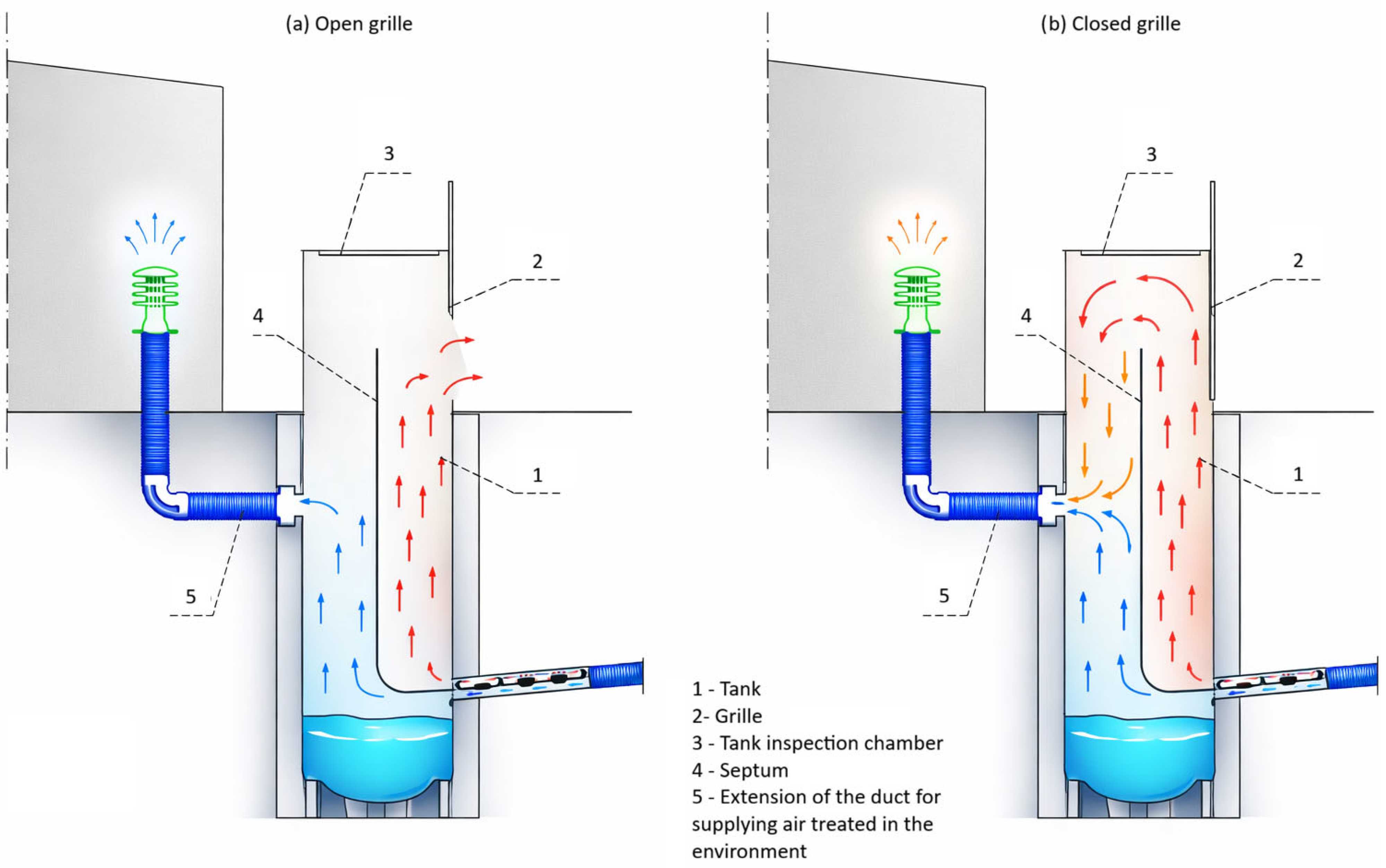
Figure 1 shows the last section of the HAGHE where the Peltier cells are installed. Outside air enters the system and passes through the horizontal geothermal pipe where it is pre-cooled or pre-heated. If the temperature falls below the dew point, condensation forms, which is collected in a tank. The air then passes over the array of Peltier cells, where the flow is divided into two:
Cold side: The air is cooled and dehumidified, undergoing sensible and latent cooling.
Hot side: The air is heated.
Inside the tank, which also acts as a mixing chamber, the two flows can combine to regulate the outlet temperature.
As shown in
Figure 1a, when the grille is opened, hot air is expelled and cold air enters the room directly to maximize cooling. On the other hand, as shown in
Figure 1b, modulating the grille opening (thus changing the hot airflow rate) allows the hot and cold flows to mix before entering the room, enabling post-heating through adiabatic mixing.
2. Materials and Methods
The system investigated in this study consisted of the terminal section of HAGHE equipped with Peltier cells. This section was not buried in the ground in order to ensure controlled boundary conditions.
Specifically, the prototype consisted of a duct internally divided by a longitudinal horizontal partition, which separated the incoming airflow into two parallel streams. The two air streams simultaneously flowed along opposite surfaces of the Peltier modules: the upper stream was in contact with the hot sides, while the lower stream was in contact with the cold sides. This configuration enabled the simultaneous heating and cooling of two separate air streams.
The thermal behavior of the system was monitored using three thermo-hygrometric probes, the first positioned near the extractor (inlet air temperature), and the others at the outlet of the hot and cold sections, whose position will be indicated later for each configuration. Their main technical specifications are reported in
Table 1. All thermo-hygrometric probes were connected to data loggers, enabling automatic acquisition and storage of time-series data. Real-time monitoring, graphical visualization, and post-processing analysis were performed for all analyses.
A hot-wire thermo-anemometer was installed at the duct outlet to measure the air velocity. IIts main technical characteristics are summarized in
Table 2.
An axial extractor fan was installed at the inlet of the duct to regulate the airflow rate within the system. The fan characteristics are summarized in
Table 3.
The airflow was controlled using an electronic speed regulator (specifications are reported in
Table 4), allowing continuous manual adjustment of fan rotational speed and consequently air velocity inside the duct. Two main airflow regimes were tested: low speed, in the range of 0.2–0.3 m/s, and medium speed, in the range of 0.5–0.6 m/s. These values were selected to analyze the influence of convective heat transfer on thermoelectric performance.
The Peltier modules, whose characteristics are presented in
Table 5, were powered by a programmable DC power supply, whose technical specifications are reported in
Table 6. During the tests, the total applied voltage varied depending on the configuration and number of modules installed. The number of Peltier cells installed in the prototype varies from 6 to 10, depending on the system configuration.
Prototype Configurations
Five different configurations of the prototype were progressively developed and tested. Each configuration represented an evolution of the previous one in terms of geometry of the duct (cylinder or parallelepiped), number of Peltier cells, airflow management, and heat dissipation strategy. The main characteristics of each configuration are summarized in
Table 7. In accordance with circular economy principles, several components used for the construction of the prototype were reused from decommissioned equipment, including aluminum heat sinks and cooling fans recovered from discarded personal computers, as well as PVC (polyvinyl chloride) and polystyrene elements from construction waste materials.
Design objective: Evaluate the baseline thermal behavior of the thermoelectric modules without auxiliary heat dissipation or insulation optimization.
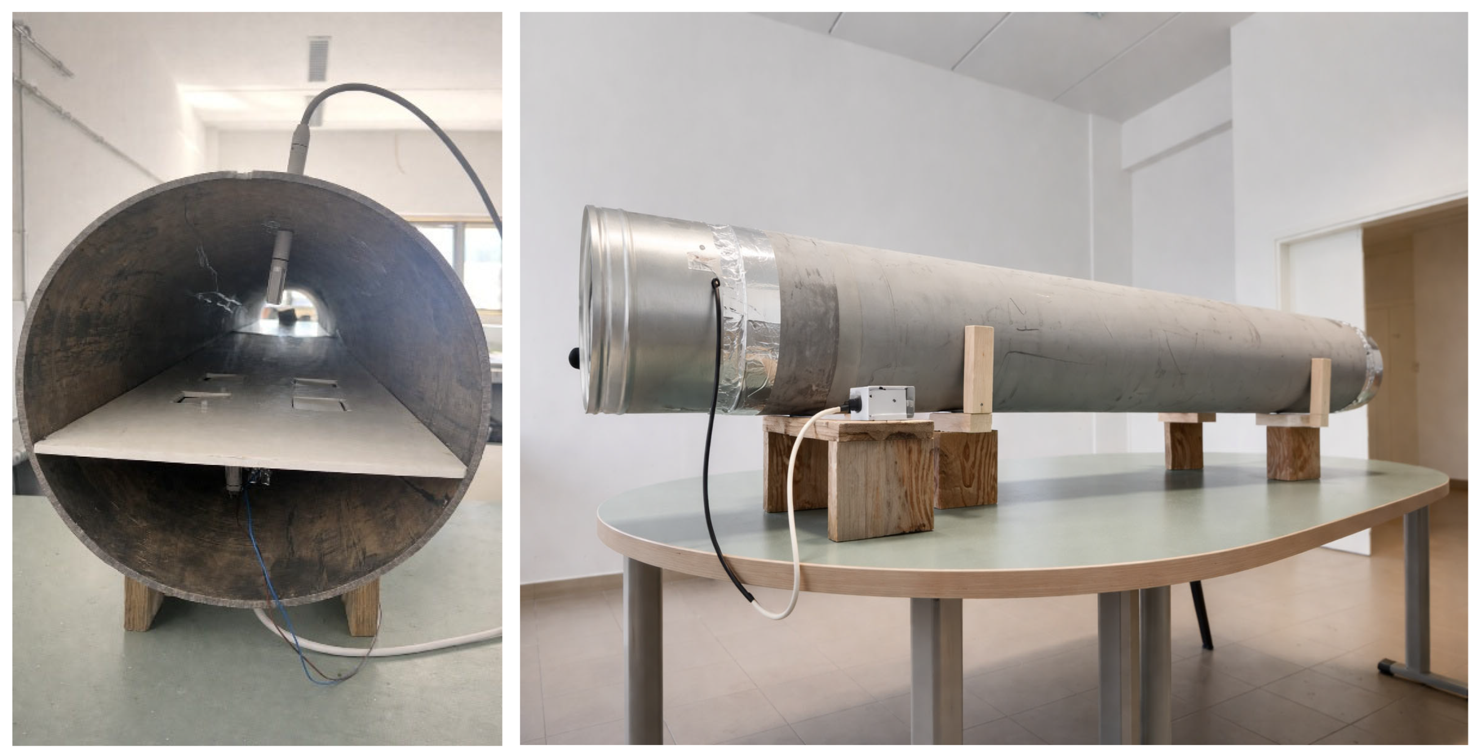
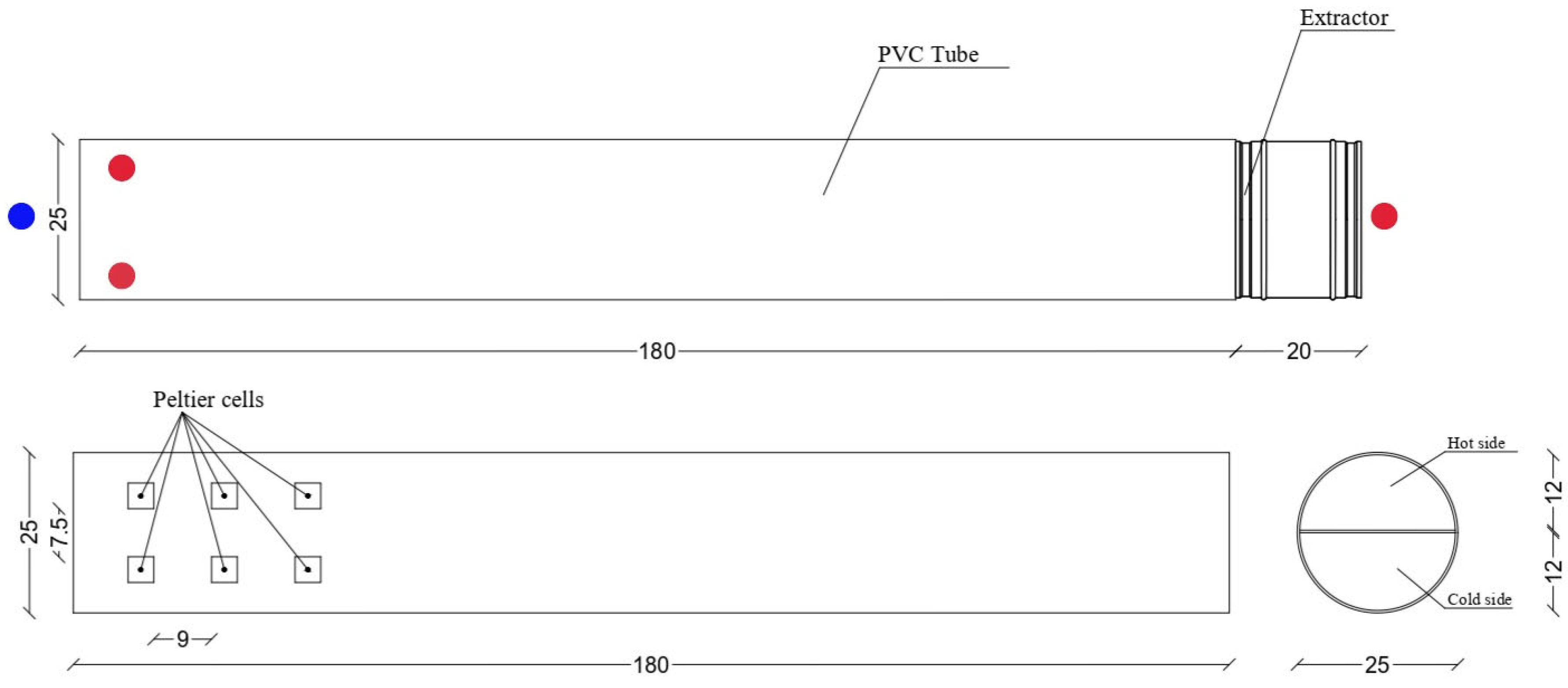
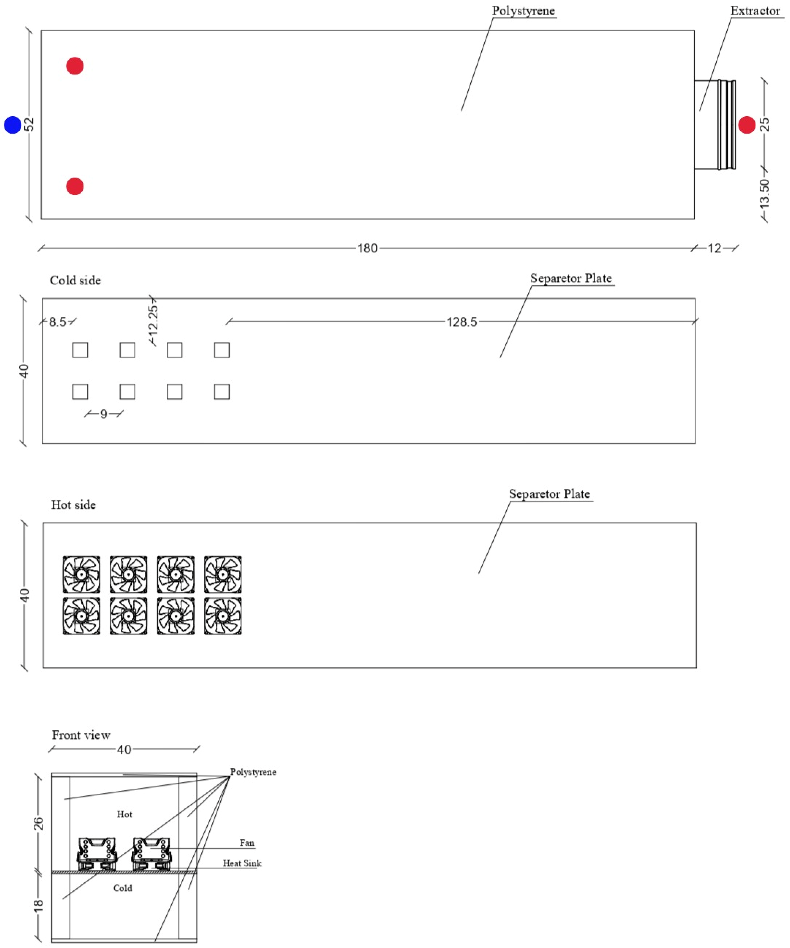
Geometry: Cylindrical PVC duct, 1.8 m in length, with an internal diameter of 25 cm, incorporating a central horizontal PVC partition that divides the cross-section into two semicircular airflow channels, each approximately 12 cm in height.
Thermoelectric modules: Six Peltier cells installed along the central partition, fixed using high-temperature thermal silicone.
Heat dissipation strategy: No heat sinks, no forced dissipation on either side.
Airflow conditions: Air velocity of 0.2–0.3 m/s.
Configuration 2—Hot-Side Dissipation (
Figure 4)
Design objective: Improve hot-side heat rejection by finned heat sinks.
Geometry: Same cylindrical PVC duct as Configuration 1, same internal partition.
Thermoelectric modules: Six Peltier cells with same arrangement as Configuration 1.
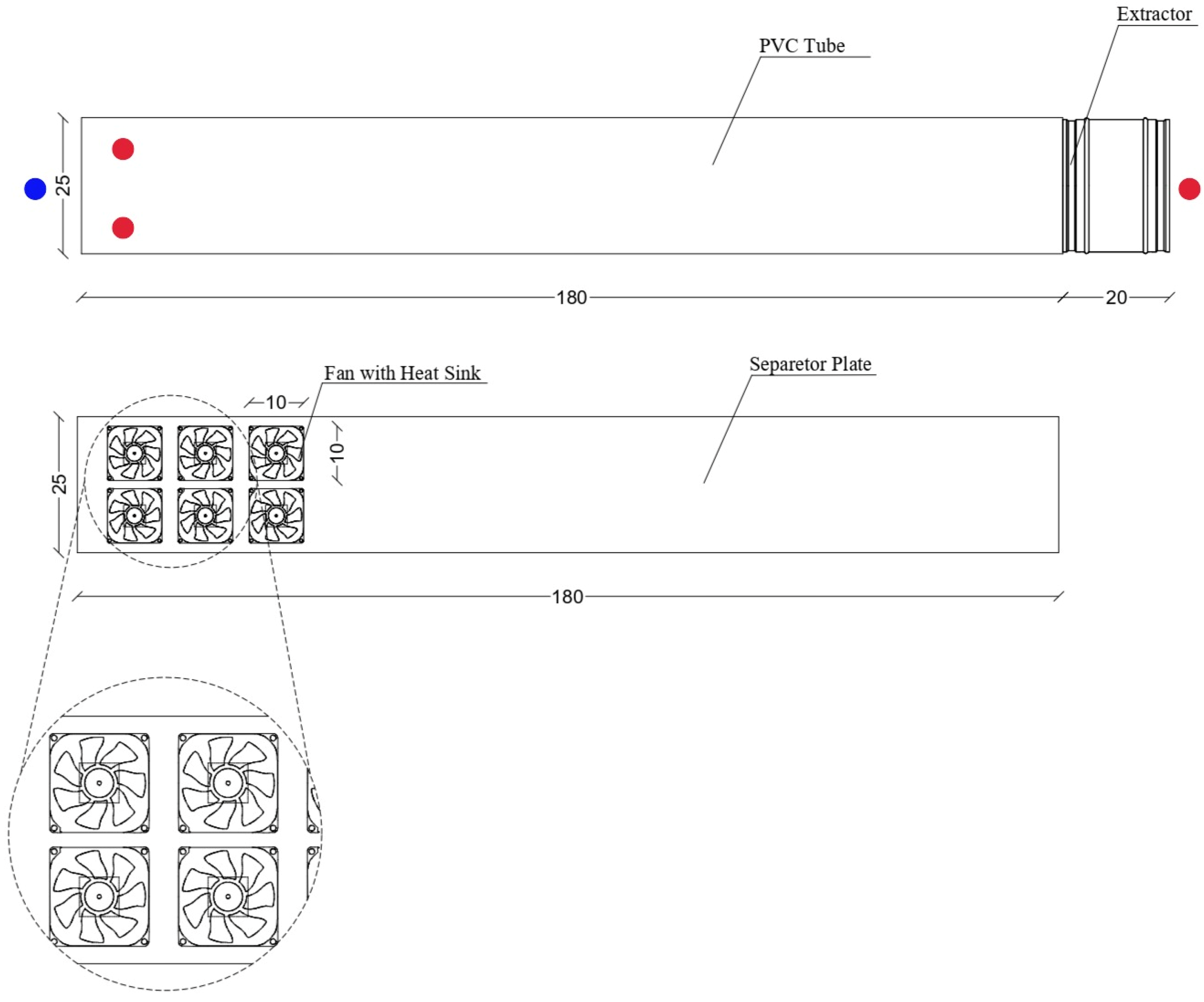
Heat dissipation strategy: Aluminum-finned heat sinks installed on the hot side, each heat sink equipped with a cooling fan; thermal paste applied at interfaces to reduce contact resistance.
Airflow conditions: Air velocity of 0.2–0.3 m/s.
Design objective: Reduce conductive heat losses through duct walls, minimize thermal interaction between the hot and cold airflow channels, and test new geometry (rectangular section).
Geometry: Rectangular duct constructed from polystyrene, 1.8 m in length, with wall thicknesses of 5 cm for the side panels and 2 cm for the top and bottom panels, featuring an integrated and fully sealed central partition.
Thermoelectric modules: Eight Peltier cells mounted along the internal partition.
Heat dissipation strategy: Aluminum heat sinks with cooling fans on the hot side.
Airflow conditions: air velocity of 0.2–0.3 m/s.
Configuration 4—Airflow Redistribution and Convective Enhancement (
Figure 7 and
Figure 8)
Design objective: Enhance convective heat transfer by redistributing airflow, increasing local air velocity, and improving air–surface contact on the cold side.
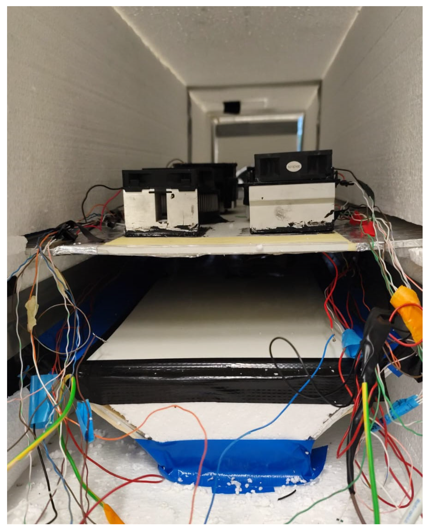
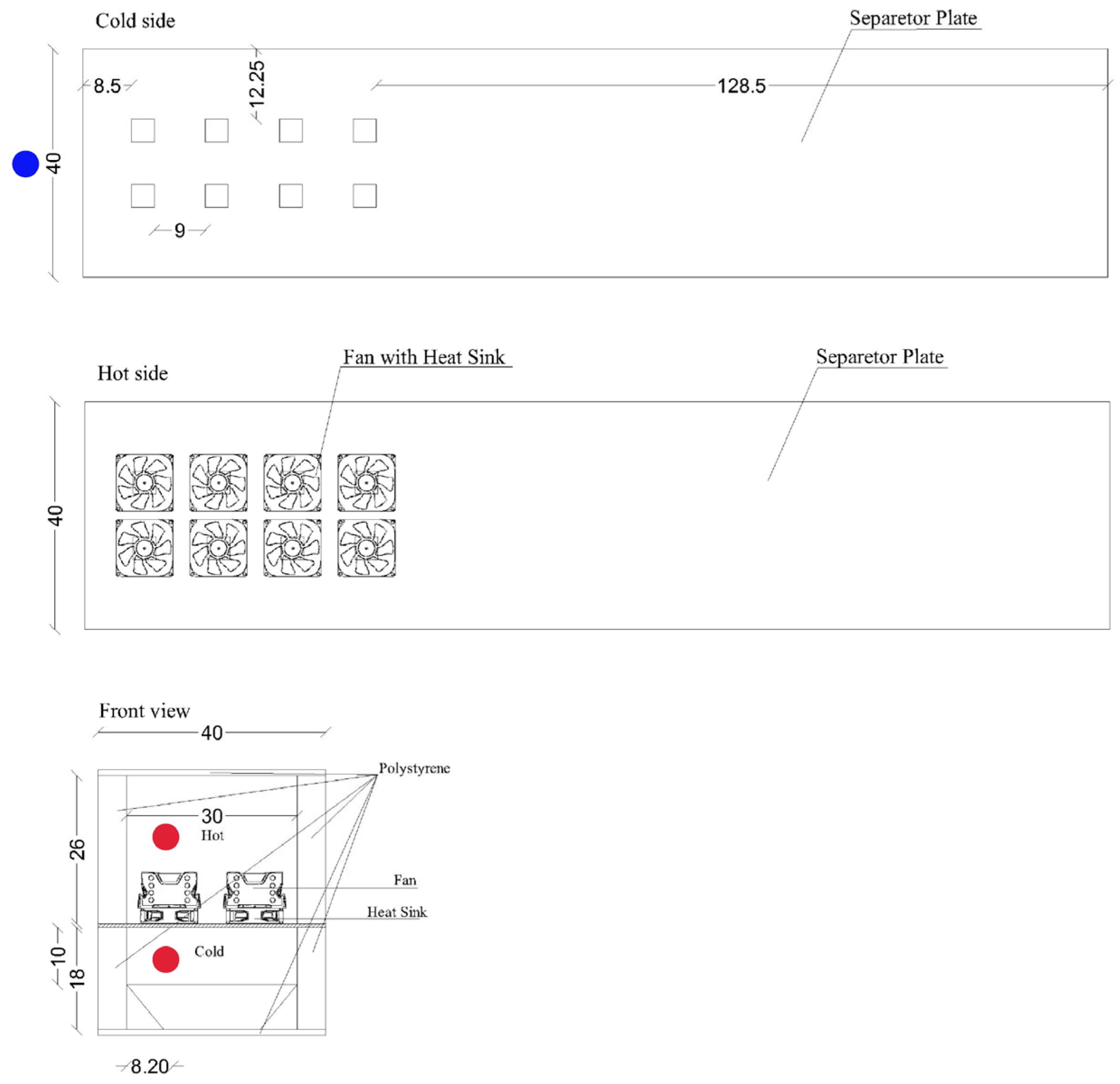
Geometry: Same rectangular polystyrene duct as in Configuration 3, with the addition of a V-shaped PVC deflector. The cold-side channel height is reduced to 10 cm to direct the maximum possible airflow toward the cold sides of the cells.
Thermoelectric modules: Eight Peltier cells with same arrangement as configuration 3.
Heat dissipation strategy: Hot-side aluminum heat sinks with cooling fans.
Airflow conditions: Air velocity of 0.5–0.6 m/s.
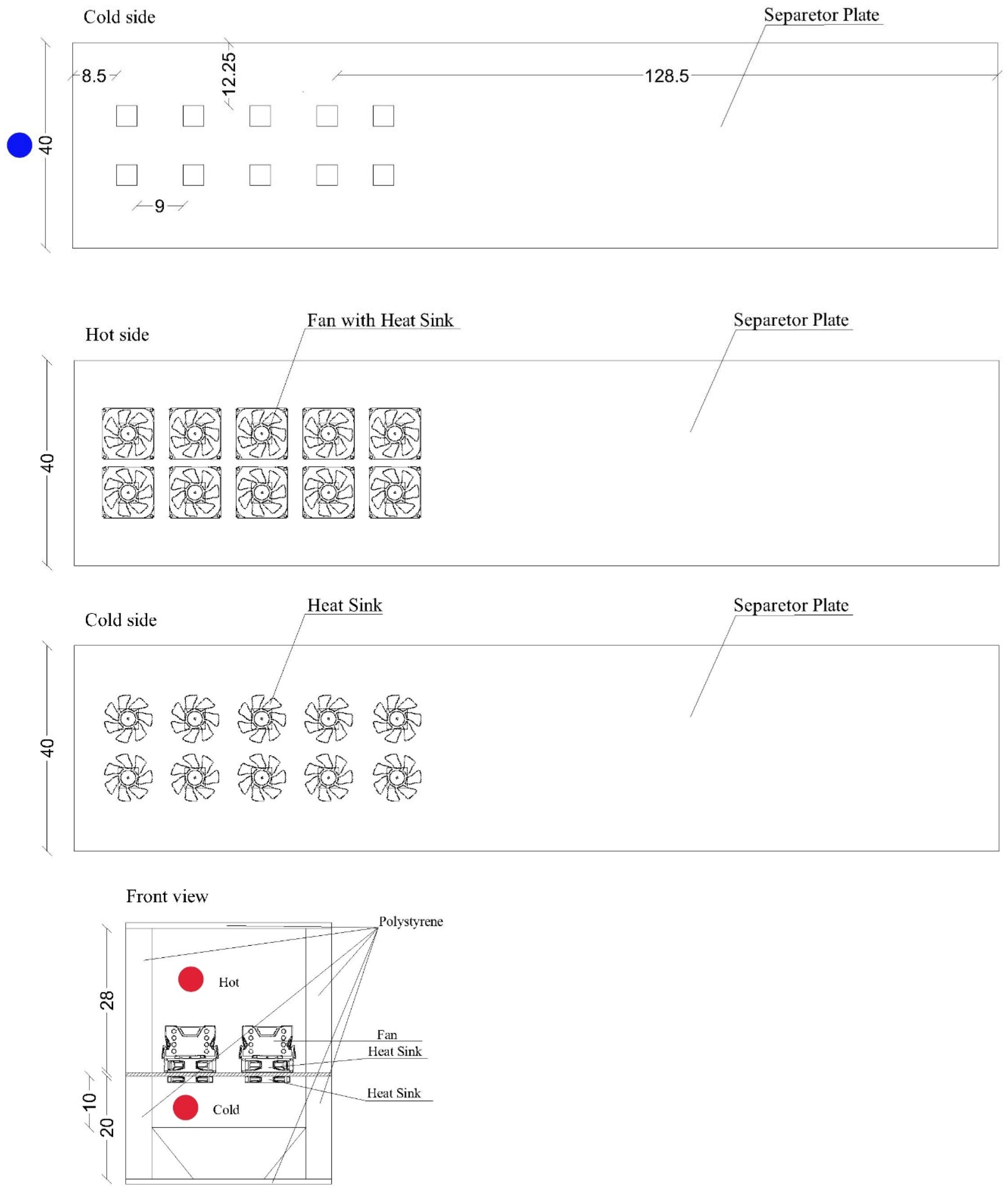
Design objective: Increase total heat exchange surface area and improve thermal symmetry between hot and cold sides, enhancing overall thermoelectric performance.
Geometry: Rectangular polystyrene duct with hot-side channel height reduced to 10 cm.
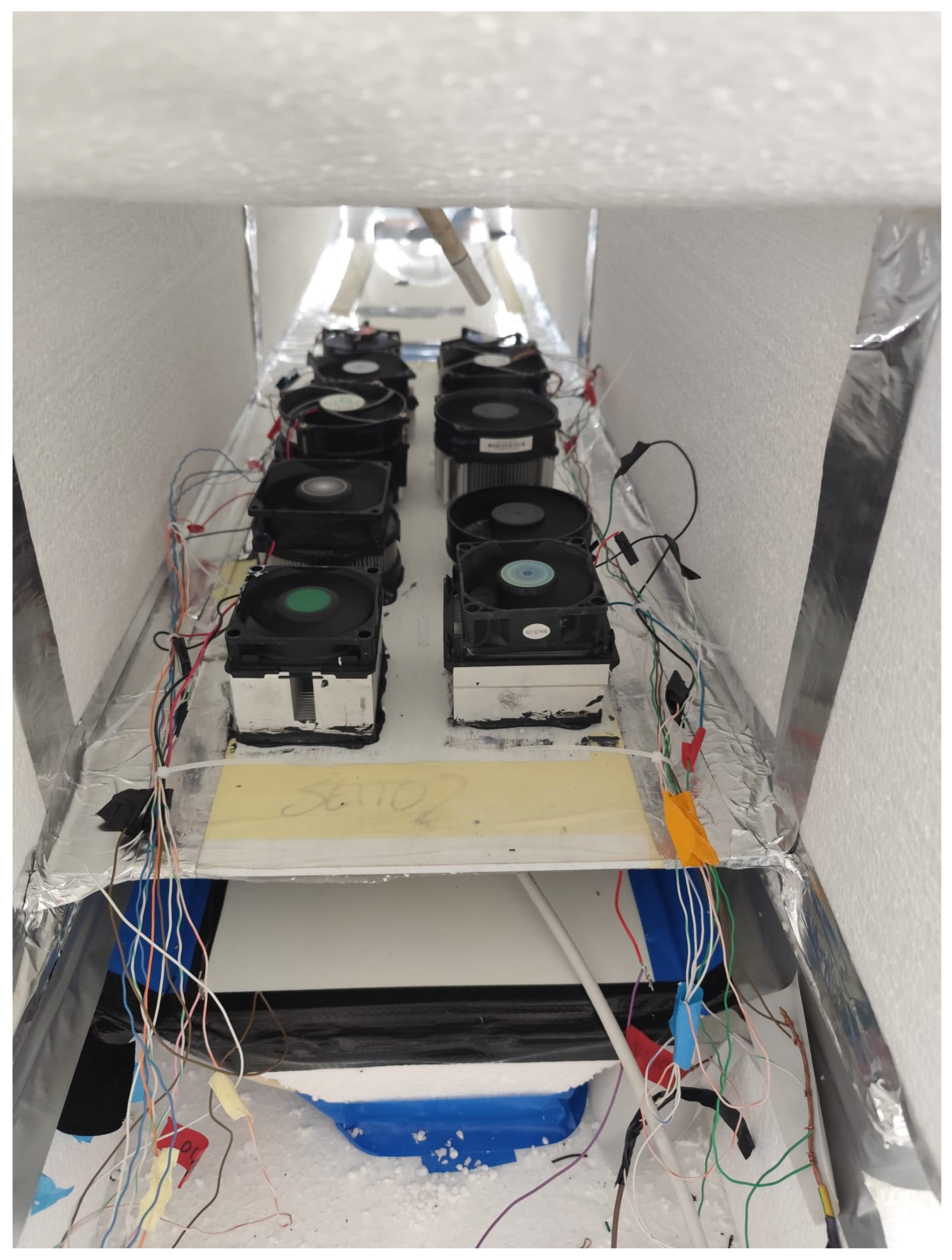
Thermoelectric modules: Ten Peltier cells uniformly distributed along the partition.
Heat dissipation strategy: Hot-side aluminum heat sinks with cooling fans, additional small aluminum heat sinks installed on the cold side.
Airflow conditions: air velocity of 0.5–0.6 m/s.
3. Results
In this section, the experimental results obtained for each investigated configuration are presented. The results are reported in terms of temperature (external temperature, hot and cold-flow temperatures) and relative humidity. For each configuration, the measured variables were recorded continuously, and the results are reported at specific intervals. The results provide a preliminary experimental indication of the proposed approach’s effectiveness.
Configuration 1—Baseline configuration (no heat dissipation)
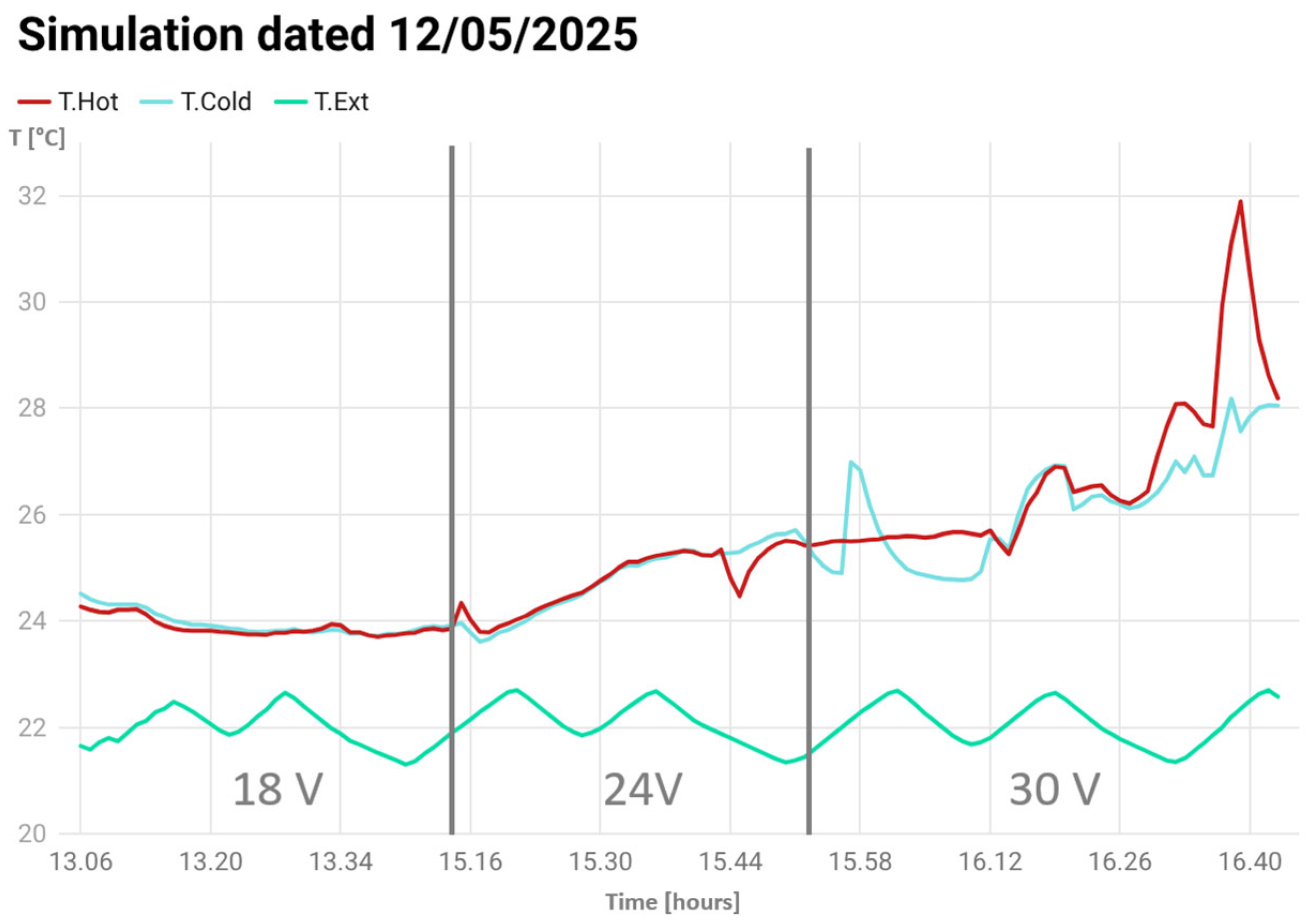
Figure 11 reports the temperature evolution of the inlet air and of the two outlet air streams for Configuration 1.
For all tested total voltages (18 V, 24 V, and 30 V), both the hot and cold air streams exhibited a temperature increase with respect to the inlet air. This behavior clearly indicates that the Peltier modules were unable to establish an effective temperature gradient between their two sides. The absence of any heat dissipation on the hot side led to rapid thermal saturation of the modules. As a consequence, the heat generated by Joule losses accumulated within the system, raising the temperature of both sides of the Peltier cells. Under these conditions, the thermoelectric effect was effectively suppressed, and the system behaved as a purely resistive heat source rather than as a heat pump.
This configuration, therefore, represents a reference case demonstrating that active heat rejection on the hot side is a necessary condition for any effective thermoelectric cooling in air-based applications.
Configuration 2—Hot-side heat dissipation
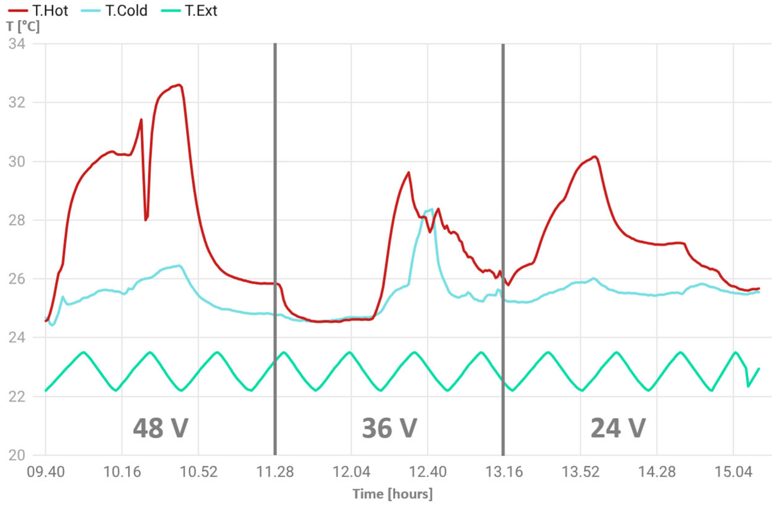
The results for Configuration 2 are shown in
Figure 12. The introduction of aluminum heat sinks and forced convection on the hot side improved thermal stability and prevented excessive temperature rise in the Peltier modules. Nevertheless, the cold air stream still did not experience a net temperature decrease relative to the inlet air.
This outcome suggests that, although hot-side dissipation is essential, it is not sufficient on its own to guarantee effective cooling. Residual conductive heat transfer through the duct walls and imperfect separation between the two air channels likely contributed to thermal short-circuiting, limiting the achievable temperature difference.
Configuration 3—Improved insulation and channel separation
Figure 13 presents the temperature trends for Configuration 3, characterized by an insulated polystyrene duct and improved separation between the hot and cold air streams.
Compared to previous configurations, a clearer differentiation between hot and cold flows was observed. The enhanced thermal insulation significantly reduced conductive heat losses through the duct walls and limited heat exchange between the two channels.
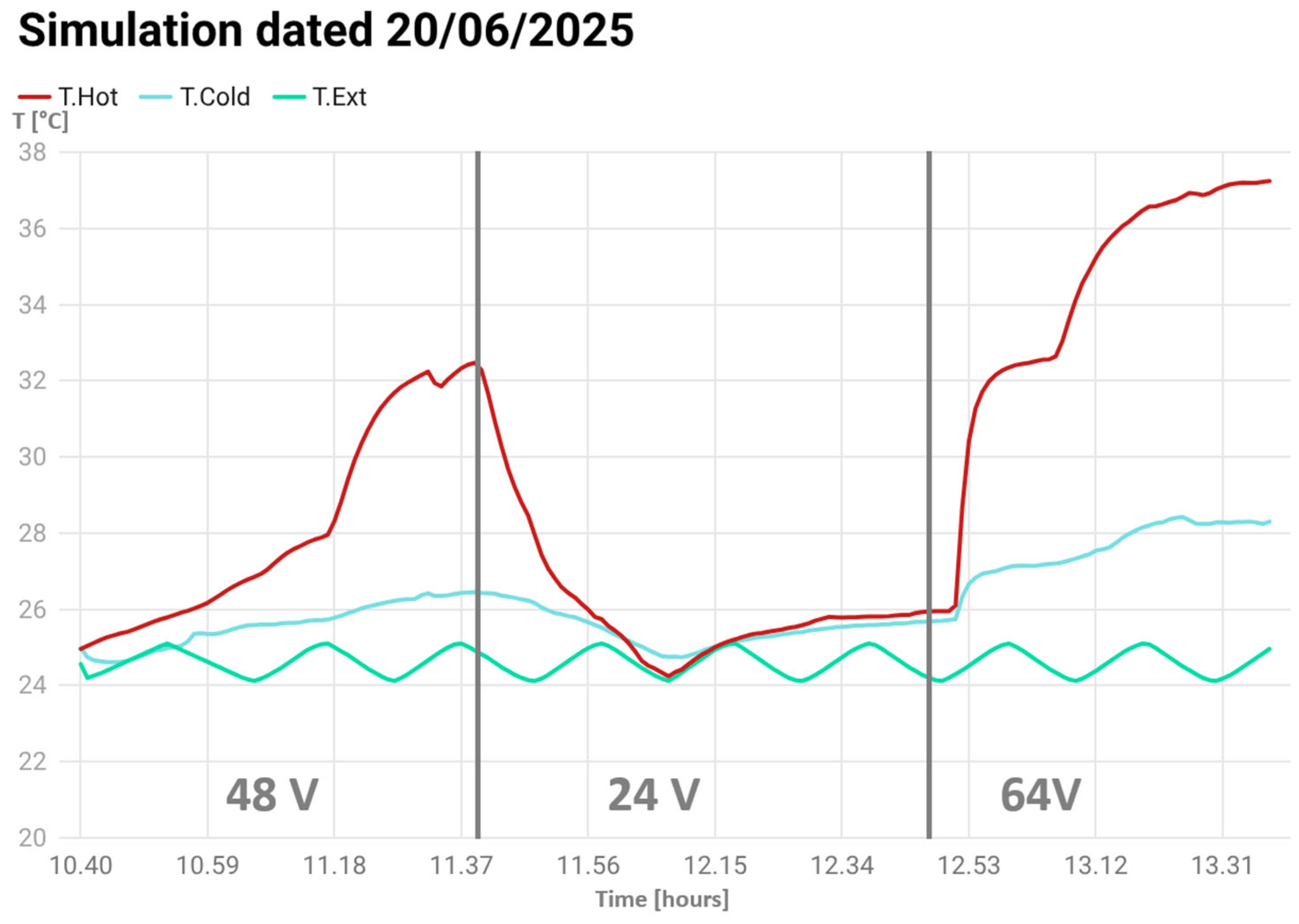
However, at the relatively low air velocities tested (0.2–0.3 m·s−1), the cooling effect on the cold side remained modest. Increasing the applied voltage mainly intensified heating on the hot side due to higher electrical power input and Joule losses. This highlights the trade-off between electrical input and convective heat removal capacity, which becomes critical at low airflow rates.
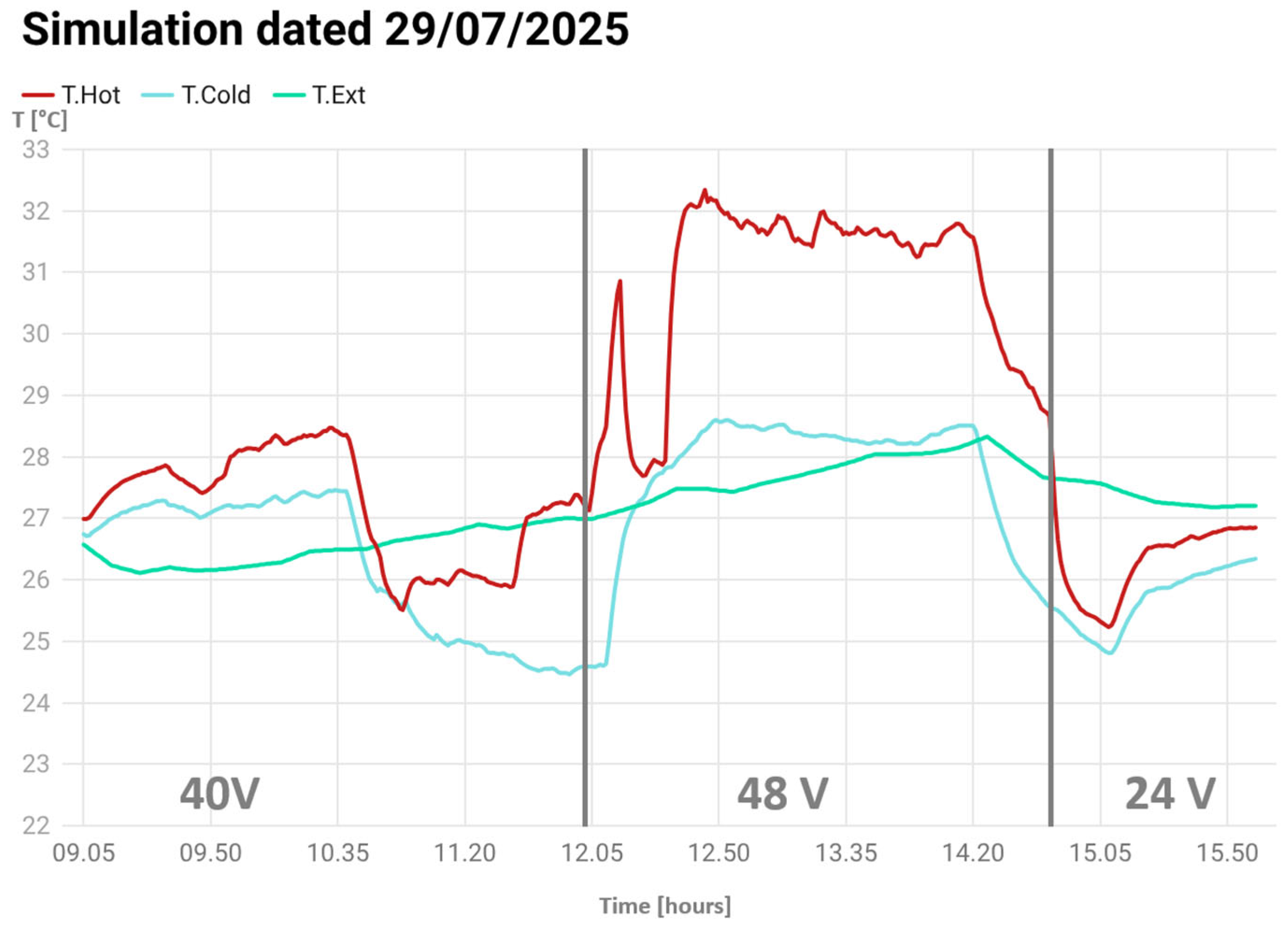
Configuration 4—Airflow redistribution and higher convective exchange
Configuration 4 marked a qualitative change in system behavior, as shown in
Figure 14. By increasing air velocity to 0.5–0.6 m·s
−1 and redistributing airflow toward the cold surfaces through a V-shaped deflector, convective heat transfer on the cold side was significantly enhanced. For the first time, simultaneous heating of the hot stream and cooling of the cold stream were consistently observed.
These results confirm that airflow management is a governing parameter in Peltier-based air treatment systems. An appropriate balance between airflow rate and applied voltage is required to prevent thermal saturation while maintaining a measurable temperature gradient.
Configuration 5—Enhanced thermal exchange on both sides
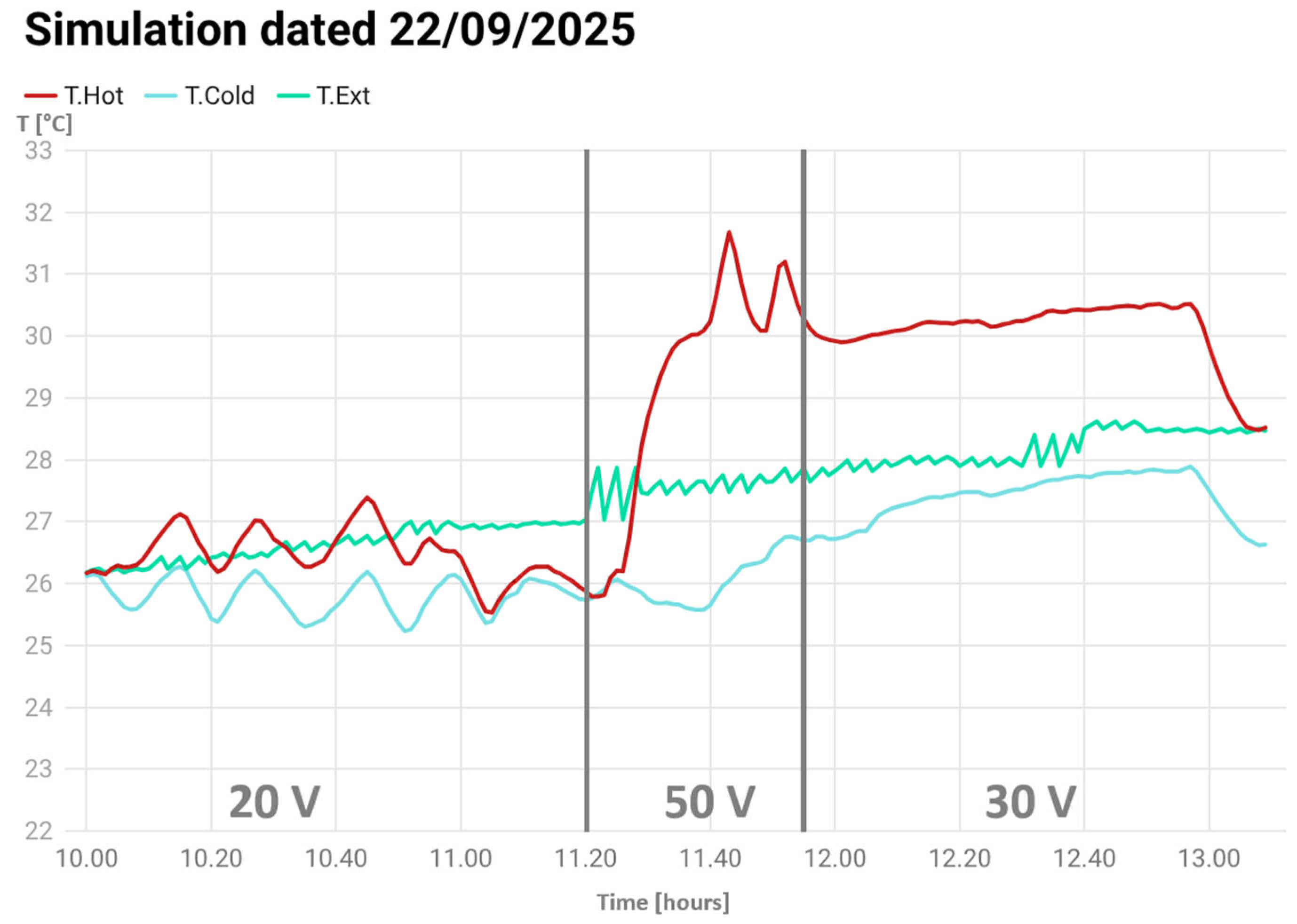
The results for Configuration 5 are reported in
Figure 15. The addition of heat sinks on both the hot and cold sides, combined with an increased number of Peltier cells, produced the most balanced and stable performance among all tested configurations. Temperature increases on the hot side and decreases on the cold side were both moderate but consistent.
This configuration demonstrates that thermal symmetry and adequate dissipation on both sides of the modules are essential to exploit the thermoelectric effect effectively. Under moderate total voltages (40–50 V) and higher airflow rates, average temperature variations of approximately +1.9 °C on the hot stream and −1.0 to −1.7 °C on the cold stream were achieved.
Overall observations
The experimental campaign gradually clarified the determining parameters that influence the performance of the proposed HAGHE–Peltier terminal module.
The experimental results indicate that the system performance is significantly influenced by heat dissipation efficiency, air velocity, and the thermal separation between the two channels.
Table 8 provides the average temperature and relative humidity values for each configuration analyzed.
In Configurations 1–3 (low air velocity: 0.2–0.3 m·s−1), effective cooling of the cold flow was not achieved. Both flows showed an increase in temperature compared to the outside air, due to Joule heating and insufficient heat dissipation, which limited the modules’ ability to generate a stable thermal gradient.
Configuration 5 showed the most balanced and stable behavior, thanks to dissipation on both sides of the modules and the greater number of cells installed, allowing an average cooling of around 1 °C in the cold flow.
4. Conclusions
The AIRcon.WATER project proposes a new device that allows for indoor air conditioning. The system is based on Peltier cells coupled with a HAGHE and is proposed as an easy-to-implement alternative to heat pumps and air handling units. This work is part of a larger project that began with a presentation of this innovative system through numerical analysis. This article presents preliminary experimental analyses conducted in a laboratory environment for the first time.
Specifically, five different configurations were evaluated with the aim of gradually implementing the system, starting with a simple PVC pipe and ending with an insulated polystyrene structure equipped with finned heat sinks and cooling fans, also varying the number of Peltier cells. The experimental results reveal that the achievable temperature difference strongly depends on both airflow velocity and applied voltage. At low airflow rates, higher temperature gradients were observed, although thermal instability and overheating occurred at elevated voltages. Conversely, increasing airflow velocity improved heat dissipation but reduced the net temperature difference across the system. The results also highlight significant thermal interference between the two air streams, indicating that imperfect separation can substantially reduce the effectiveness of the thermoelectric modules.
The findings confirm that while thermoelectric modules can provide localized heating and cooling when coupled with air-based systems, their performance is highly sensitive to operating conditions. The experimental evidence demonstrates that assumptions commonly made in conceptual studies may overestimate achievable performance if heat dissipation and airflow interactions are neglected.
By isolating the terminal section, this study clarifies the intrinsic limitations of Peltier-based modules in hybrid geothermal systems, providing valuable insights for future design optimization.
The main strengths lie in the use of recycled or reused components (e.g., heat sinks and fans from decommissioned equipment), compliance with the principles of the circular economy, and design flexibility, adapted to the materials available in the laboratory while maintaining good geometric and functional fidelity to previous numerical models.
This study provides a solid experimental basis for the future development of innovative geothermal technologies with low environmental impact based on the use of thermoelectric modules for the production of double thermal effects.
However, it is essential to emphasize that the system analyzed is an initial laboratory-scale prototype designed to isolate and study exclusively the behavior of the thermoelectric terminal section. The conduit was not buried, and therefore the contribution of soil thermal pretreatment, which is a key element of the complete HAGHE system, was not considered. The absence of coupling with the ground deliberately excluded the effects of thermal inertia and temperature stabilization typical of horizontal geothermal systems.
Consequently, the results obtained should be interpreted as a preliminary validation of the behavior of the Peltier module under controlled conditions. Integration with the ground and geometric and fluid dynamic optimization of the complete system offer a concrete margin for improvement in overall performance, both in terms of temperature difference and thermo-hygrometric control.
Furthermore, a limitation of the present study is that repeated experimental trials were not performed. Future work will include systematic repetitions to statistically quantify repeatability and experimental variability.
Finally, future research should focus on improving heat dissipation strategies, optimizing duct separation, and extending the analysis to full-scale ground-coupled installations.
Author Contributions
Conceptualization, C.B., M.B., I.P. and P.M.C.; Methodology, C.B., M.B., I.P. and P.M.C.; Software, G.F.F., C.B., G.R., M.S. and P.M.C.; Validation, C.B., M.B., I.P. and P.M.C.; Formal analysis, G.F.F., C.B., G.R., M.S., M.B., I.P. and P.M.C.; Investigation, G.F.F., C.B., G.R., M.S., M.B., I.P. and P.M.C.; Resources, C.B. and P.M.C.; Data curation, G.F.F., C.B., G.R., M.S., M.B., I.P. and P.M.C.; Writing—original draft, G.F.F., C.B., G.R., M.B. and P.M.C.; Writing—review & editing, C.B., M.B., I.P. and P.M.C.; Visualization, C.B., M.B., I.P. and P.M.C.; Supervision, C.B., M.B. and P.M.C.; Project administration, C.B., M.B. and P.M.C.; Funding acquisition, C.B. and M.B. All authors have read and agreed to the published version of the manuscript.
Funding
This study was funded by the “European Commission—Next Generation EU”—PNRR M4—C2–investimento 1.1: Fondo per il Programma Nazionale di Ricerca e Progetti di Rilevante Interesse Nazionale (PRIN)—PRIN 2022PNRR cod. F53D2300971 0001 “AIRcon.WATER (Air conditioning and Water from Air, by Thermal Earth Recovery)”, Università del SALENTO CUP F53D23009710001, Università degli Studi di PALERMO CUP B53D23027020001.
Data Availability Statement
The original contributions presented in this study are included in the article. Further inquiries can be directed to the corresponding author.
Conflicts of Interest
The authors declare no conflicts of interest.
References
- Tsemekidi-Tzeiranaki, S.; Labanca, N.; Cuniberti, B.; Toleikyte, A.; Zangheri, P.; Bertoldi, P. Analysis of the Annual Reports 2018 Under the Energy Efficiency Directive—Summary Report; Publications Office of the European Union: Luxembourg, 2019. [Google Scholar]
- Economidou, M.; Todeschi, V.; Bertoldi, P.; D’AGostino, D.; Zangheri, P.; Castellazzi, L. Review of 50 years of EU energy efficiency policies for buildings. Energy Build. 2020, 225, 110322. [Google Scholar] [CrossRef] [Scilit]
- Dinh, H.B.; Nguyen-Cong, H.; Lee, B.Y.; Kim, Y.S. Thermal and economic benefits of a coil-column ground heat exchanger with recycled concrete backfill in horizontal ground source heat pump applications. Case Stud. Therm. Eng. 2025, 72, 106344. [Google Scholar] [CrossRef] [Scilit]
- Gondal, I.A.; Masood, S.A.; Amjad, M. Review of geothermal energy development efforts in Pakistan and way forward. Renew. Sustain. Energy Rev. 2017, 71, 687–696. [Google Scholar] [CrossRef] [Scilit]
- Wu, H.; Wang, S.; Zhu, D. Modelling and evaluation of cooling capacity of earth–air–pipe systems. Energy Convers. Manag. 2005, 48, 1462–1471. [Google Scholar] [CrossRef] [Scilit]
- Bisoniya, T.S.; Kumar, A.; Baredar, P. Experimental and analytical studies of earth–air heat exchanger (EAHE) systems in India: A review. Renew. Sustain. Energy Rev. 2013, 19, 238–246. [Google Scholar] [CrossRef] [Scilit]
- Baglivo, C.; Congedo, P.M.; Laforgia, D. Air cooled heat pump coupled with Horizontal Air-Ground Heat Exchanger (HAGHE) for Zero Energy Buildings in the Mediterranean climate. Energy Procedia 2017, 140, 2–12. [Google Scholar] [CrossRef] [Scilit]
- Imanloozadeh, A.; Lubitz, W.D. Characteristics, design, and optimization of earth-air heat exchangers: A review. Renew. Sustain. Energy Rev. 2026, 230, 116677. [Google Scholar] [CrossRef] [Scilit]
- Wu, J.; Li, H.; Shao, G. Research on a ground source heat pump with horizontal ground heat exchanger buried in water-bearing sandy soil. Geothermics 2025, 131, 103405. [Google Scholar] [CrossRef] [Scilit]
- Kerme, E.D.; Alzahrani, W.S.; Fung, A.S.; Leong, W.H. Experimental investigation of ground-source heat pump system coupled to vertical and horizontal ground loops: A case study. Renew. Energy 2024, 236, 121482. [Google Scholar] [CrossRef] [Scilit]
- Gao, W.; Masum, S.; Qadrdan, M.; Thomas, H.R. A numerical study on performance efficiency of a low-temperature horizontal ground-source heat pump system. Energy Build. 2023, 291, 113137. [Google Scholar] [CrossRef] [Scilit]
- Baglivo, C.; Bonuso, S.; Congedo, P.M. Performance Analysis of Air Cooled Heat Pump Coupled with Horizontal Air Ground Heat Exchanger in the Mediterranean Climate. Energies 2018, 11, 2704. [Google Scholar] [CrossRef] [Scilit]
- Sehli, A.; Hasni, A.; Tamali, M. The Potential of Earth-air Heat Exchangers for Low Energy Cooling of Buildings in South Algeria. Energy Procedia 2012, 18, 496–506. [Google Scholar] [CrossRef] [Scilit]
- Al-Ajmi, F.; Loveday, D.L.; Hanby, V.I. The cooling potential of earth–air heat exchangers for domestic buildings in a desert climate. Build. Environ. 2006, 41, 235–244. [Google Scholar] [CrossRef] [Scilit]
- Hollmuller, P.; Lachal, B. Cooling and preheating with buried pipe systems: Monitoring, simulation and economic aspects. Energy Build. 2001, 33, 509–518. [Google Scholar] [CrossRef] [Scilit]
- Zhang, D.; Zhang, J.; Liu, C.; Yan, C.; Ji, J.; An, Z. Performance measurement and configuration optimization based on or-thogonal simulation method of earth-to-air heat exchange system in cold-arid climate. Energy Build. 2024, 308, 114001. [Google Scholar] [CrossRef] [Scilit]
- Ascione, F.; D’Agostino, D.; Marino, C.; Minichiello, F. Earth-to-air heat exchanger for NZEB in Mediterranean climate. Renew. Energy 2016, 99, 553–563. [Google Scholar] [CrossRef] [Scilit]
- Kapıcıoğlu, A.; Esen, H. Effect of long-term nanofluid usage on horizontal ground source heat pump performance. Renew. Energy 2024, 237, 121777. [Google Scholar] [CrossRef] [Scilit]
- Lanahan, M.; Tabares-Velasco, P.C. Seasonal thermal-energy storage: A critical review on BTES systems, modeling, and system design for higher system efficiency. Energies 2017, 10, 743. [Google Scholar] [CrossRef] [Scilit]
- Congedo, P.; Lorusso, C.; Baglivo, C.; Milanese, M.; Raimondo, L. Experimental validation of horizontal air-ground heat exchangers (HAGHE) for ventilation systems. Geothermics 2019, 80, 78–85. [Google Scholar] [CrossRef] [Scilit]
- Niu, F.; Yu, Y.; Yu, D.; Li, H. Heat and mass transfer performance analysis and cooling capacity prediction of earth to air heat exchanger. Appl. Energy 2015, 137, 211–221. [Google Scholar] [CrossRef] [Scilit]
- Cannistraro, M.; Trancossi, M. Enhancement of indoor comfort in the presence of large glazed radiant surfaces by a local heat pump system based on Peltier cells. Therm. Sci. Eng. Prog. 2019, 14, 100388. [Google Scholar] [CrossRef] [Scilit]
- Mannella, G.A.; La Carrubba, V.; Brucato, V. Peltier cells as temperature control elements: Experimental characterization and modeling. Appl. Therm. Eng. 2014, 63, 234–245. [Google Scholar] [CrossRef] [Scilit]
- Casano, G.; Piva, S. Experimental investigation of the performance of a thermoelectric generator based on Peltier cells. Exp. Therm. Fluid Sci. 2011, 35, 660–669. [Google Scholar] [CrossRef] [Scilit]
- Shi, L.; Abed, A.M.; Fayed, M.; Abdulghani, Z.R.; Anqi, A.E.; Khadimallah, M.A.; Moria, H.; Wae-Hayee, M. Economic cost analysis of air-cooling process using different numbers of Peltier modules; Experimental case study. Case Stud. Therm. Eng. 2023, 41, 102627. [Google Scholar] [CrossRef] [Scilit]
- Freire, L.O.; Navarrete, L.M.; Corrales, B.P.; Castillo, J.N. Efficiency in thermoelectric generators based on Peltier cells. Energy Rep. 2021, 7, 355–361. [Google Scholar] [CrossRef] [Scilit]
- Dipova, N. Design and development of peltier assisted infrared drying based soil moisture content device. KSCE J. Civ. Eng. 2019, 23, 29–36. [Google Scholar] [CrossRef] [Scilit]
- Dizaji, H.S.; Pourhedayat, S.; Anqi, A.E.; Aldawi, F.; Alsenani, T.R.; Moria, H. Enhanced Peltier refrigerator using an innovative hot-side heat-rejection mechanism; Experimental study under both transient and steady-state conditions. Energy 2024, 309, 133132. [Google Scholar] [CrossRef] [Scilit]
- Usman, M.; Haq, H.W.U.; Riaz, F.; Ali, M.S.; Masood, M.I.; Fouad, Y.; Chatha, S.K.; Bashir, M.N. Investigation of a novel heat extraction configuration for boosting photovoltaic panel efficiency. Case Stud. Therm. Eng. 2025, 70, 106104. [Google Scholar] [CrossRef] [Scilit]
- Wang, L.; Xue, Y.; Zhu, L.; Cao, X.; Li, X.; Ranjith, P.G. Fracture evolution of granite under cyclic thermal shocks: Effects of liquid nitrogen cooling on strength, toughness, and acoustic emission characteristics. Therm. Sci. Eng. Prog. 2026, 70, 104507. [Google Scholar] [CrossRef] [Scilit]
- Li, X.; Zhu, L.; Liu, J.; Cao, Z.; Xue, Y.; Dang, F. Fracture evolution and mechanical deterioration of granite under cyclic thermal and liquid nitrogen cryogenic impact. Phys. Fluids 2025, 37, 086652. [Google Scholar] [CrossRef] [Scilit]
- Congedo, P.M.; Baglivo, C.; Negro, G. A New Device Hypothesis for Water Extraction from Air and Basic Air Condition System in Developing Countries. Energies 2021, 14, 4507. [Google Scholar] [CrossRef] [Scilit]
- Spagnolo, M.; Congedo, P.M.; Buscemi, A.; Falcicchia Ferrara, G.; Bonomolo, M.; Baglivo, C. Geothermal–Peltier Hybrid System for Air Cooling and Water Recovery. Energies 2025, 18, 4115. [Google Scholar] [CrossRef] [Scilit]
- Baglivo, C.; Buscemi, A.; Spagnolo, M.; Bonomolo, M.; Lo Brano, V.; Congedo, P.M. Toward a Sustainable Indoor Environment: Coupling Geothermal Cooling with Water Recovery Through EAHX Systems. Energies 2025, 18, 2297. [Google Scholar] [CrossRef] [Scilit]
- DIN EN IEC 60751:2023-06; Industrial Platinum Resistance Thermometers and Platinum Temperature Sensors (IEC 60751:2022); German Version EN IEC 60751:2022. Deutsches Institut für Normung: Berlin, Germany, 2023.
- UNI EN ISO 7726:2026; Ergonomics of the Thermal Environment—Instruments for Measuring and Monitoring Physical Quantities (EN ISO 7726:2025, ISO 7726:2025). UNI—Ente Italiano di Normazione: Milan, Italy, 2026.
Figure 1.
Conceptual scheme of the proposed system, the red and blue arrows represent hot and cold flows, respectively.
Figure 1.
Conceptual scheme of the proposed system, the red and blue arrows represent hot and cold flows, respectively.
Figure 2.
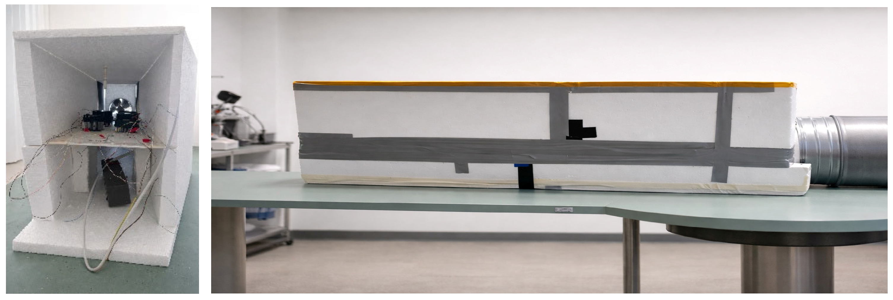
First configuration—prototype photo.
Figure 2.
First configuration—prototype photo.
Figure 3.
First configuration—technical drawing. Thermo-hygrometric probes in red, hot-wire thermo-anemometer in blue.
Figure 3.
First configuration—technical drawing. Thermo-hygrometric probes in red, hot-wire thermo-anemometer in blue.
Figure 4.
Second configuration—technical drawing. Thermo-hygrometric probes in red, hot-wire thermo-anemometer in blue.
Figure 4.
Second configuration—technical drawing. Thermo-hygrometric probes in red, hot-wire thermo-anemometer in blue.
Figure 5.
Third configuration—Prototype photo.
Figure 5.
Third configuration—Prototype photo.
Figure 6.
Third configuration—technical drawing. Thermo-hygrometric probes in red, hot-wire thermo-anemometer in blue.
Figure 6.
Third configuration—technical drawing. Thermo-hygrometric probes in red, hot-wire thermo-anemometer in blue.
Figure 7.
Fourth configuration—prototype photo.
Figure 7.
Fourth configuration—prototype photo.
Figure 8.
Fourth configuration—technical drawing. Thermo-hygrometric probes in red, hot-wire thermo-anemometer in blue.
Figure 8.
Fourth configuration—technical drawing. Thermo-hygrometric probes in red, hot-wire thermo-anemometer in blue.
Figure 9.
Fifth configuration—prototype photo.
Figure 9.
Fifth configuration—prototype photo.
Figure 10.
Fifth configuration—technical drawing. Thermo-hygrometric probes in red, hot-wire thermo-anemometer in blue.
Figure 10.
Fifth configuration—technical drawing. Thermo-hygrometric probes in red, hot-wire thermo-anemometer in blue.
Figure 11.
First configuration—temperature trends.
Figure 11.
First configuration—temperature trends.
Figure 12.
Second configuration—temperature trends.
Figure 12.
Second configuration—temperature trends.
Figure 13.
Third configuration—temperature trends.
Figure 13.
Third configuration—temperature trends.
Figure 14.
Fourth configuration—temperature trends.
Figure 14.
Fourth configuration—temperature trends.
Figure 15.
Fifth configuration—temperature trends.
Figure 15.
Fifth configuration—temperature trends.
Table 1.
Thermo-hygrometric probes technical specifications.
Table 1.
Thermo-hygrometric probes technical specifications.
| Categories | Parameter | Specification |
|---|
| Temperature | Principle | Pt100 Class A IEC60751 (DIN Class A) |
| Measuring range | [−50;100] °C |
| Accuracy | ±0.15 K @ 0 °C |
| Output | Pt100 DIN-IEC 751 table (DIN EN IEC 60751:2023-06) [35] |
| Resolution | 0.01 °C |
| Response time (T90) | 4 s (1 m/s airflow) |
| Long-term stability | <0.1 °C/year |
| Relative humidity | Principle | Capacitive |
| Measuring range | [0;100]% |
| Accuracy | ±1% RH (5–95%) |
| Long-term stability | <±1%/year |
| Response time (T90) | 10 s (1 m/s airflow) |
| Hysteresis | <1% |
| Resolution | 0.1% |
| General Information | Protection grade | IP66 |
| Operative temperature | [−50;100] °C |
Table 2.
Hot-wire thermo-anemometer technical specifications.
Table 2.
Hot-wire thermo-anemometer technical specifications.
| Category | Parameter | Specification |
|---|
| Air Speed Measurement | Measuring range | 0.01 ÷ 20 m/s (with label showing 0.2 ÷ 20 m/s) |
| Threshold (minimum detectable speed) | 0.01 m/s |
| Resolution | 0.01 m/s |
| Response time | 0.1 s |
| Sampling frequency | 10 Hz |
| Accuracy (typical) | ±0.06 m/s (0.1–0.4 m/s) ±0.08 m/s (0.4–3.0 m/s) ±3.5% of reading (3.0–20 m/s) |
| Standards & Compliance | Norm conformity | UNI EN ISO 7726:2026 [36] (air speed metrology) |
| Environmental | Protection grade | IP54 |
| Operating temperature | −40 … +85 °C |
| Mechanical | Cable length | typically 1 m (may vary by unit/version) |
Table 3.
Axial extractor fan technical specifications.
Table 3.
Axial extractor fan technical specifications.
| Category | Parameter | Specification |
|---|
| Airflow | Nominal diameter | 250 mm |
| Airflow rate | 1000 m3/h |
| Pressure | Static pressure | 72 Pa |
| Acoustic pressure level | 56 dB(A) |
| Electrical Data | Supply voltage | ~220–230 V |
| Supply frequency | 50–60 Hz |
| Motor speed | 1400 rpm |
| Motor power | 86 W |
| Thermal Limits | Maximum operating temperature | 40 °C |
| Protection | Degree of protection | IP X2 |
| Insulation class | Class 1 |
Table 4.
Electronic speed regulator technical specifications.
Table 4.
Electronic speed regulator technical specifications.
| Category | Parameter | Specification |
|---|
| Electrical Data | Supply voltage | 220–240 V AC |
| Supply frequency | 50 Hz |
| Rated current | 1.5 A |
| Maximum load current | 1.5 A |
| Control Features | Regulation type | Electronic speed control |
| Direction control | Non-reversible |
| Control mode | Continuous manual adjustment |
| Installation | Mounting type | Wall mounted |
| Compliance | Conformity marking | CE, UKCA |
Table 5.
Peltier cells specifications.
Table 5.
Peltier cells specifications.
| Parameter | Value |
|---|
| Technology | Thermoelectric Peltier Module |
| Cooling Power (Qc max) | 83 W |
| Maximum Current | 6.7 A |
| Maximum Voltage | 20 V DC |
| Maximum Temperature Difference (ΔT max) | 71 °C |
| Electrical Resistance | 2.44 Ω |
| Dimensions (L × W × H) | 40 × 40 × 3.3 mm |
| Number of Stages | Single stage |
| Lead Wires | UL Style 1569 |
| Compliance | RoHS compliant |
| Typical Applications | Electronic cooling, temperature control |
Table 6.
Programmable DC power supply technical specifications.
Table 6.
Programmable DC power supply technical specifications.
| Category | Parameter | Specification |
|---|
| Input (AC) | Supply voltage range | 90–264 V AC (single-phase) |
| Frequency | 45–66 Hz |
| Power Factor | Active PFC |
| Output (DC) | Output voltage range | 0–200 V |
| Output current range | 0–10 A |
| Power rating | 0–640 W |
| Performance | Auto-ranging output stage | Yes (voltage/current trade-off) |
| Display | Color display for values/status |
| Protections | Overvoltage protection (OVP) | Yes |
| Overcurrent protection (OCP) | Yes |
| Overpower protection (OPP) | Yes |
| Overtemperature protection (OT) | Yes |
| Remote & Control | Remote sensing | Yes |
| Connectivity (optional) | USB/USB + Ethernet/USB + analog |
| Protocols supported | SCPI, Modbus RTU |
| Mechanical | Mounting type | Desktop/bench |
| Safety output connector | 4 mm safety banana sockets |
| Compliance | RoHS compliant | Yes |
| Warranty | Manufacturer warranty | 2 years |
Table 7.
Settings for each configuration.
Table 7.
Settings for each configuration.
| Configuration | Technical Evolution | Duct Geometry | Duct Material | Hot Section Size (cm) | Cold Section Size (cm) | Peltier Cells Numbers | Heat Sinks | Position of Heat Sinks | Air Velocity (m/s) | Total Applied Voltage (V) |
|---|
| 1 | No dissipation | Cylinder | PVC | 12 (radius size) | 12 (radius size) | 6 | no | - | 0.2–0.3 | 18–24–30 |
| 2 | Hot side dissipation | Cylinder | PVC | 12 (radius size) | 12 (radius size) | 6 | yes | hot side | 0.2–0.3 | 24–36–48 |
| 3 | Improved insulation | Parallelepiped | Polystyrene | 40 × 26 (base × height) | 40 × 18 (base × height) | 8 | yes | hot side | 0.2–0.3 | 24–48–64 |
| 4 | Aerodynamic optimization | Parallelepiped | Polystyrene | 40 × 28 (base × height) | 40 × 10 (base × height) | 8 | yes | hot side | 0.5–0.6 | 24–40–48 |
| 5 | Both sides dissipation | Parallelepiped | Polystyrene | 40 × 28 (base × height) | 40 × 10 (base × height) | 10 | yes | both sides | 0.5–0.6 | 20–30–50 |
Table 8.
Average temperature and relative humidity values for each configuration.
Table 8.
Average temperature and relative humidity values for each configuration.
| Configuration | Average Temperature of External Air (°C) | Hot-Side Airflow Average Temperature (°C) | Cold-Side Airflow Average Temperature (°C) | Average Relative Humidity of External Air (%) | Average Relative Humidity of the Hot Air (%) | Average Relative Humidity of the Cold Air (%) |
|---|
| 1 | 22.04 | 25.26 | 25.07 | 46.22 | 45.69 | 46.43 |
| 2 | 22.85 | 27.38 | 25.45 | 45.37 | 42.38 | 47.87 |
| 3 | 24.60 | 29.08 | 26.11 | 44.92 | 41.90 | 48.89 |
| 4 | 27.14 | 28.46 | 26.72 | 43.22 | 42.68 | 45.56 |
| 5 | 27.42 | 28.4 | 26.46 | 38.87 | 35.48 | 39.54 |
| Disclaimer/Publisher’s Note: The statements, opinions and data contained in all publications are solely those of the individual author(s) and contributor(s) and not of MDPI and/or the editor(s). MDPI and/or the editor(s) disclaim responsibility for any injury to people or property resulting from any ideas, methods, instructions or products referred to in the content. |




 ,
,