1. Introduction
The increasing demand for compact and efficient thermal management solutions in industrial and energy systems has renewed interest in plate heat exchangers (PHEs). Applications such as power generation and chemical processing often require heat exchangers capable of delivering high effectiveness within restricted volumes and under low pressure-drop constraints. Among compact exchanger architectures, PHEs remain a leading candidate due to their high surface-area-to-volume ratio, modular construction, and geometric adaptability [
1,
2].
Geometric and morphological features play a decisive role in determining PHE performance. Corrugated surfaces, particularly chevron profiles, enhance convective transport by promoting secondary flows and periodic boundary-layer disruption, although these effects are typically accompanied by higher frictional losses [
3,
4]. Experimental and numerical investigations show that chevron angles between 30° and 60° can improve mixing and Nusselt number but also increase pressure drop [
5,
6]. Additional factors such as flow maldistribution, laminar–transitional behavior, and localized temperature gradients further influence the thermo-hydraulic balance in multi-channel configurations [
6,
7].
Alternative morphologies such as zigzag, sinusoidal, and cross-corrugated plates have been developed to reduce hydraulic penalties while retaining convective enhancement. Cross-corrugated geometries may reduce pressure drop by approximately 15% relative to sinusoidal designs while maintaining comparable heat-transfer performance [
8]. Sinusoidal corrugations produce smoother contraction and expansion zones that promote gradual flow mixing and reduced frictional losses, particularly in low-Reynolds-number regimes [
9,
10]. Broader surveys on compact heat exchangers highlight that curvature-continuous surfaces—including wavy, sinusoidal, and TPMS-inspired structures—suppress large-scale separation while maintaining boundary-layer renewal, offering a balanced tradeoff between heat transfer enhancement and frictional dissipation [
11]. Additive manufacturing studies further demonstrate that triply periodic minimal surface (TPMS) cores achieve high surface-area-to-volume ratios and smoother inertial oscillations, providing additional insights for sinusoidal PHE designs [
12]. Surface features such as ribs, perforations, and dimples have also been used to locally intensify mixing and reduce entropy generation [
13].
While numerous studies have examined the thermo-hydraulic tradeoff in plate heat exchangers, there remains practical value in conducting comparative assessments under a single and consistent set of operating conditions. Such consistency supports clearer interpretation of how channel spacing and surface morphology jointly influence thermal performance and hydraulic cost. Enhancements in convective coefficients often increase friction factor and pressure drop, which can reduce overall system efficiency [
14,
15]. To quantify this balance, several Performance Evaluation Criteria (PECs) have been developed to normalize heat-transfer gains with a hydraulic penalty. However, their application across different geometries and operating conditions is not always uniform [
16,
17,
18]. Many existing studies emphasize corrugation effects, with comparatively fewer works examining channel spacing, coolant properties, and flow arrangement within a unified boundary-condition framework.
Recent optimization-driven research highlights that heat-exchanger performance reflects multiple interconnected tradeoffs between thermal effectiveness and hydraulic cost. Techniques such as genetic algorithms, particle swarm optimization, and teaching–learning-based optimization have been used to obtain Pareto-optimal configurations in compact and plate-fin exchangers [
19]. Application-focused work has shown that geometric choices are strongly influenced by system-level constraints, such as footprint, mass flow rate, and allowable pumping power [
20]. Taguchi and Design of Experiments methods have also been applied to map global design parameters, including inter-plate spacing and morphology variations [
21]. CFD-based studies underscore the importance of consistent boundary conditions, mesh independence, and turbulence modeling for credible comparison across designs [
22]. Parametric analyses in latent-heat storage systems further emphasize the need to define system constants and operational envelopes before optimization [
23]. Economic optimization frameworks additionally link pressure-drop penalties to operating cost, reinforcing the relevance of evaluating performance under constrained hydraulic budgets [
24].
Although earlier optimization studies examined geometric and morphological effects, many analyze individual parameters or rely on case-specific boundary conditions. The present work contributes a structured and interpretable comparative framework in which inter-plate spacing, surface morphology, and thermal hydraulic metrics are evaluated using a uniform set of operating conditions. This approach facilitates transparent comparison of the coupled influence of confinement and corrugation on exchanger performance.
The relevance of such a framework is evident when a fixed wall-temperature boundary condition is applied since the resulting temperature rise along the coolant stream depends strongly on geometric confinement. Under these conditions, inter-plate spacing influences the hydraulic diameter, Reynolds number development, entrance-length effects, and the evolution of thermal and hydrodynamic boundary layers. Although corrugated geometries have been extensively studied, systematic comparisons of flat, chevron, and curvature-continuous profiles under identical boundary conditions are less common in the literature. This limits the development of generalized guidelines for compact exchangers operating under restricted pumping power.
The present study provides a structured CFD-based assessment for plate heat exchangers subjected to a fixed wall temperature. Using water as the coolant and applying consistent inlet and wall boundary conditions, the methodology integrates three elements. First, the influence of inter-plate spacing is quantified to identify a thermally effective and hydraulically feasible operating window. Second, surface morphology is varied through both chevron and sinusoidal corrugations to compare impingement-driven and curvature-driven flow modification. Third, a composite performance evaluation is used to place each configuration within a heat-transfer and pressure-loss tradeoff space. The outcome is a set of comparative insights and practical design guidelines that may assist early-stage engineering of compact heat exchangers for industrial and energy-related applications. The novelty of the present work lies not in introducing new corrugation geometries but in providing a consistent and structured comparative assessment of flat, chevron, and sinusoidal plates under identical operating and boundary conditions, thereby isolating the influence of morphology and channel spacing within a unified evaluation framework.
2. Design Framework
The framework is intended as a structured comparative tool that connects geometric design, flow field characteristics, and thermal hydraulic performance. The framework proposed in this study establishes this connection by integrating system-level constraints, tunable geometric parameters, and surface-scale flow-control strategies under a consistent thermo-hydraulic design philosophy. Its objective is to enhance convective transport while maintaining hydraulic feasibility and spatial compactness, which are essential requirements in modern industrial and energy-conversion systems.
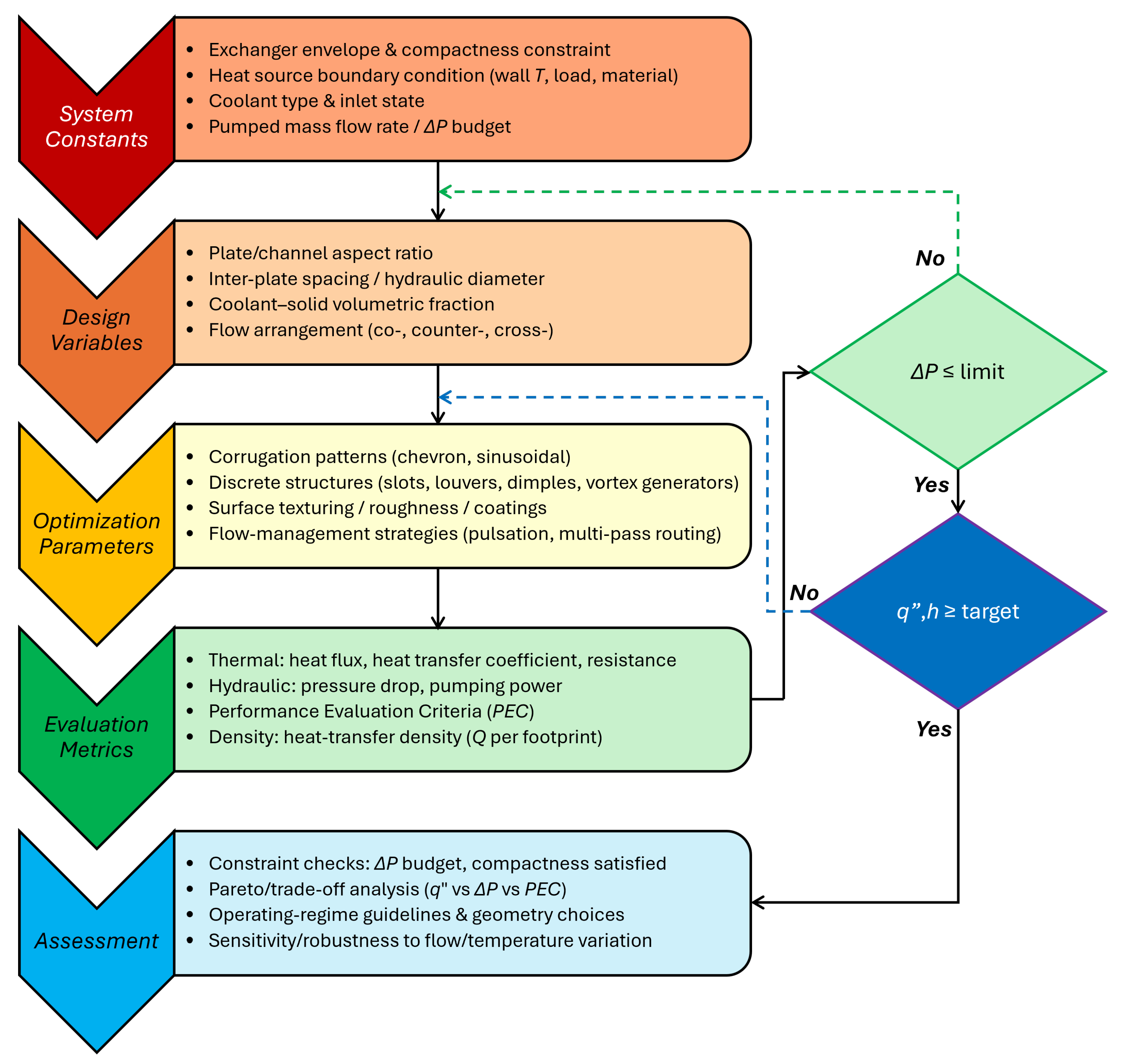
In contrast to design approaches that rely primarily on empirical correlations or focus on isolated geometric parameters, the present framework consolidates these elements into a coherent comparative workflow. While not a replacement for full optimization, this approach provides practical guidance by linking geometric choices to their thermo–hydraulic implications within a unified CFD-based assessment. The methodology, illustrated schematically in
Figure 1, is organized into four hierarchical layers: (
i) fixed system constants that define the operating envelope, (
ii) tunable design variables that establish the flow regime, (
iii) optimization parameters that influence near-wall mixing and surface-area utilization, and (
iv) evaluation metrics that quantify thermal performance and hydraulic efficiency.
This structured workflow allows progressive refinement across scales. It begins with the definition of boundary conditions and progresses to the implementation of morphology-induced flow perturbations. Each iteration ensures that performance variations remain consistent with geometric and operating constraints. By embedding transport physics within the comparative evaluation process, the framework provides an interpretable and computationally practical pathway for the design of compact heat exchangers across a range of operating conditions.
2.1. System Constants
The system constants define the physical and operational envelope within which the heat exchanger operates. These parameters are non-variable and reflect design constraints imposed by system integration, available pumping power, and target heat loads. The prescribed footprint and compactness ratio represent dimensional limitations typical of compact thermal systems used in industrial and energy applications.
The imposed thermal condition is represented through a constant wall-temperature boundary condition, which provides a uniform driving potential for convection. This enables direct comparison of geometry-induced transport variations. The coolant and its thermophysical properties—density, viscosity, thermal conductivity, and specific heat—are fixed to represent a realistic working fluid at expected operating temperatures. The inlet condition, defined by a prescribed temperature and mass flow rate, determines the characteristic Reynolds number and thereby the internal flow regime.
A fixed pressure-drop budget sets the upper limit for allowable hydraulic losses and directly correlates with the mechanical work required from the pump. This constraint ensures hydraulic feasibility and maintains energy efficiency. Collectively, these constants establish the optimization boundaries, governing geometric modifications and providing the reference frame for evaluating thermal performance improvements within practical system constraints.
2.2. Design Variables
The design variables represent tunable geometric and flow-structural parameters that influence convective transport, velocity uniformity, and pressure distribution within the plate channels. These variables define the hydrodynamic field and determine the key non-dimensional parameters—primarily Reynolds and Nusselt numbers, that characterize thermo-hydraulic behavior.
Principal geometric descriptors include the plate-to-channel aspect ratio, which controls hydrodynamic development length and wall exposure, and the inter-plate spacing (or hydraulic diameter), which governs velocity gradients and near-wall shear rates. Narrower spacing enhances shear and boundary-layer interaction but increases frictional resistance. Wider spacing lowers pressure losses yet weakens temperature gradients and convective intensity. The coolant-to-solid volumetric fraction defines the distribution of active fluid volume relative to heat-transfer area, affecting both heat capacity and compactness.
Flow configuration introduces an additional degree of freedom. The alignment of adjacent channels—co-current, counter-current, or cross-flow—modifies the mean temperature difference and influences overall exchanger effectiveness. Together, these geometric and flow variables define the design space for implementing surface morphologies and secondary-flow mechanisms. Through their combined optimization, the system achieves enhanced convective transport under constrained pumping-power and compactness requirements.
2.3. Optimization Parameters
The optimization parameters define the surface-level and flow-management strategies that modulate the local flow field to enhance heat transfer, fluid mixing, and wall-shear distribution. These modifications introduce controlled perturbations that promote boundary-layer disruption and energize near-wall regions, which typically dominate thermal resistance in laminar and transitional regimes.
Surface morphologies such as chevron and sinusoidal corrugations are employed as passive enhancement features to redistribute momentum and thermal energy across the channel height. Chevron patterns create alternating converging and diverging flow paths, generating strong secondary vortices and impingement zones that periodically thin the boundary layer and elevate wall heat flux. Sinusoidal geometries, by contrast, impose smooth oscillatory accelerations and decelerations that sustain quasi-periodic reattachment without inducing large-scale separation. This results in efficient convective transport with reduced viscous dissipation.
Additional enhancement mechanisms include discrete flow-interruption features such as dimples, ribs, slots, and vortex generators. These elements locally intensify mixing through shear-layer roll-up, vortex shedding, and wake impingement. At smaller scales, surface texturing, roughness control, and hydrophilic or hydrophobic coatings modify near-wall hydrodynamics by altering viscous-sublayer behavior and interfacial thermal resistance. Dynamic techniques such as flow pulsation, wall vibration, and multi-pass routing can further redistribute thermal loads and homogenize temperature gradients within the exchanger core.
Each optimization parameter contributes differently to the thermal–hydraulic balance. Some mechanisms promote turbulence and increase the local Nusselt number, while others focus on reorganizing flow to minimize energy dissipation per unit heat-transfer gain. Within the present framework, these effects are integrated and assessed under a constant pumping-power constraint to ensure that surface-induced enhancements remain both thermodynamically efficient and hydraulically sustainable.
2.4. Evaluation Metrics
The evaluation metrics establish a quantitative basis for assessing thermal performance, hydraulic losses, and overall thermo-hydraulic efficiency. These indicators enable direct comparison among configurations and provide insight into tradeoffs between convective enhancement and pressure losses. The metrics are organized into three categories: (i) thermal performance indicators, (ii) hydraulic loss indicators, and (iii) integrated performance metrics.
2.4.1. Thermal Performance Indicators
Wall-averaged heat flux:
where
Q is the total heat-transfer rate and
is the effective heat-transfer area. This metric quantifies the system’s ability to dissipate thermal energy per unit surface area, reflecting the combined influence of convection and surface morphology.
Overall heat-transfer coefficient:
where the log-mean temperature difference is
Here, is the wall temperature, while and are the inlet and outlet coolant temperatures, respectively.
Thermal resistance:
where
is the mean wall–fluid temperature difference. Lower
values correspond to higher heat-transfer efficiency.
Heat-transfer density (compactness ratio):
where
V is the exchanger core volume. This volumetric measure links heat-transfer rate to spatial footprint.
2.4.2. Hydraulic Loss Indicators
Pressure drop:
where
and
are the inlet and outlet static pressures. Maintaining a low
is essential to ensure energy-efficient operation under constrained hydraulic budgets.
2.4.3. Integrated Performance Indicators
Before introducing the composite performance metric, the Nusselt number and the Darcy friction factor used in this study are defined for clarity. The Nusselt number is
where
h is the convective heat transfer coefficient,
is the hydraulic diameter of the channel, and
k is the thermal conductivity of the fluid. The Darcy friction factor is given by
where
is the pressure drop across the channel length
L,
is the fluid density, and
is the mean flow velocity.
Performance Evaluation Criterion (PEC):
where
and
f are the Nusselt number and Darcy friction factor, respectively, and subscript “0” denotes the baseline flat-plate configuration. Values of
indicate that thermal gains outweigh the hydraulic penalty.
These metrics are evaluated sequentially within the framework. Hydraulic feasibility is verified first by ensuring that the pressure drop remains below the design threshold. Thermal performance is then assessed using , h, and , followed by volumetric efficiency through . The PEC finally serves as a composite indicator of overall performance.
2.5. Framework Integration and Decision Logic
The structured workflow integrates the defined constants, variables, and metrics into an iterative decision-making loop that links thermal enhancement with hydraulic feasibility and system compactness. Each design iteration begins with the specification of system constants and geometric parameters, followed by the introduction of surface-level optimization features that modify local flow dynamics. The resulting thermo-hydraulic fields are evaluated using the established performance metrics to verify compliance with energetic and geometric constraints. It is noted that the objective of this framework is not to introduce new enhancement geometries but to evaluate existing corrugation types within a consistent computational setting, which supports clearer interpretation of their relative thermal and hydraulic behavior.
Design feasibility is assessed through sequential checkpoints. The pressure-drop limit ensures hydraulic viability, while the wall heat flux and overall heat-transfer coefficient confirm thermal adequacy. When these criteria are not satisfied, the framework adaptively tunes geometric parameters or surface morphologies within the permissible design space. This process couples convective transport and viscous dissipation physics into a closed feedback optimization cycle, ensuring that thermal enhancements remain energetically sustainable.
In this study, the framework is demonstrated through CFD analyses of plate channels featuring flat, chevron, and sinusoidal morphologies. This implementation establishes a quantitative baseline that links morphology-induced flow modulation to measurable thermal and hydraulic outcomes. Future extensions will incorporate multi-objective optimization routines, such as Pareto-front evaluations of heat-transfer density versus pumping power and multi-objective genetic algorithms for optimal designs under combined constraints.
3. Methodology
3.1. CFD Setup
Three-dimensional steady-state simulations were performed using the finite-volume solver ANSYS Fluent (2025 R1) to resolve coupled momentum and thermal transport within the plate-channel geometries. The incompressible single-phase flow of liquid water was modeled by solving the Reynolds-averaged conservation equations of mass, momentum, and energy.
The governing equations are presented below.
Energy:
where
and
are the turbulence-induced eddy viscosity and turbulent thermal conductivity, respectively.
Turbulence closure was achieved using the Shear Stress Transport (SST) k– model, selected for its capability to capture flow separation, streamline curvature, and periodic reattachment in corrugated and sinusoidal plate geometries. The SST formulation blends the near-wall accuracy of the k– model with the free-stream stability of the k– model, providing robust predictions across the laminar to transitional regime characteristic of compact plate channels.
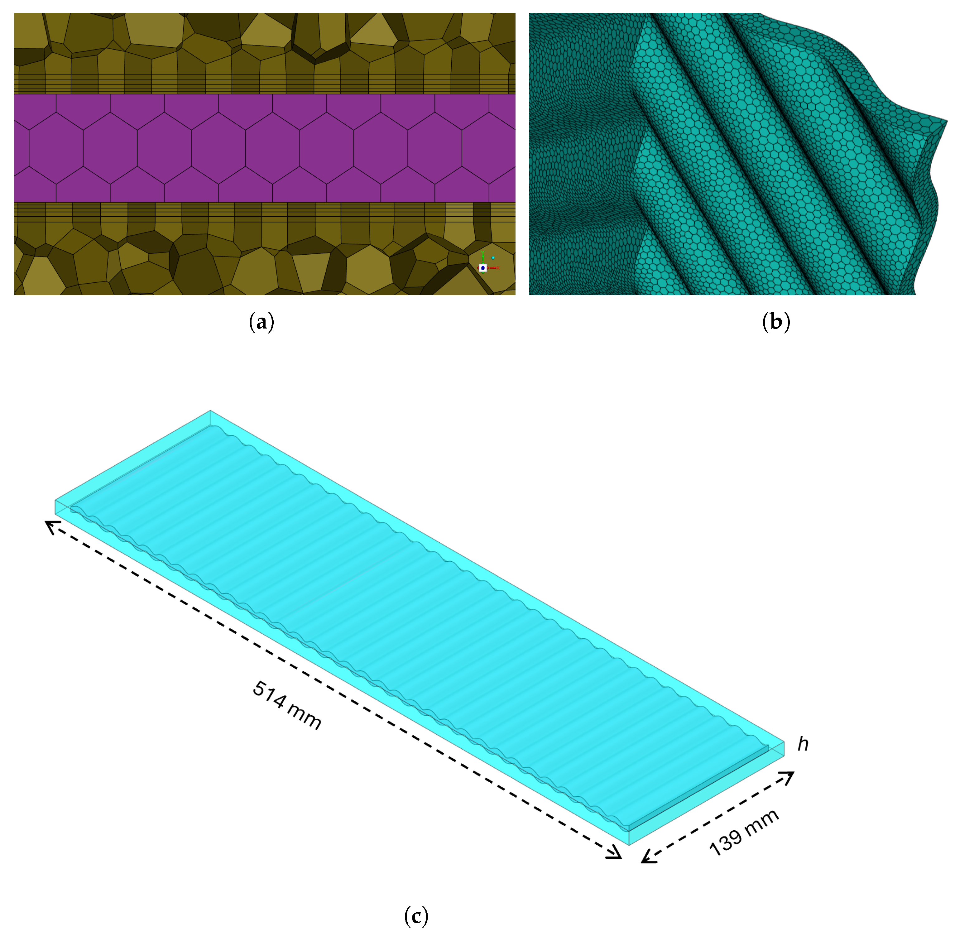
A hexahedral-dominant mesh with local refinement near all solid boundaries was generated to resolve steep velocity and temperature gradients. A minimum of 5 inflation layers were applied along all fluid–solid interfaces, and the first-cell height was chosen to maintain
, ensuring compatibility with SST near-wall requirements. The generated mesh shown in
Figure 2 demonstrated excellent quality, characterized by an average surface-mesh skewness of 0.006 and a cell orthogonal quality of 0.94, indicative of a highly refined and well-resolved discretization. Mesh independence was confirmed by monitoring global pressure drop and wall heat flux, with differences between successive refinements remaining below 1.5%.
The computational domain corresponds to a single plate channel of length 514 mm and width 139 mm, with the channel gap
h varied parametrically to assess its influence on thermal–hydraulic performance, as illustrated in
Figure 2c. All lateral surfaces are modeled as no-slip adiabatic walls. To exploit geometric repetition and reduce computational cost, either symmetry or periodic boundary conditions are applied on the top and bottom surfaces depending on the plate morphology. For the flat-plate baseline, symmetry planes are used to represent a repeating section of a ten-plate stack while preserving the essential flow and thermal characteristics. Likewise, symmetry condition is also applied for the sinusoidal out-of-phase configuration, where adjacent plates exhibit mirror symmetry. For the chevron corrugations and the sinusoidal in-phase geometry, streamwise periodic boundary conditions are imposed to represent the repeating channel module and its fully developed nature. At the inlet, a uniform velocity profile is prescribed in the streamwise direction, and pressure-outlet condition is applied at the outlet boundary.
A second-order upwind scheme was used for spatial discretization of the convective terms, while pressure–velocity coupling employed the SIMPLE algorithm. Convergence was achieved when all residuals dropped below and the monitored surface-averaged heat-transfer rate varied by less than 0.1% over 500–1000 iterations.
Boundary conditions were specified to maintain a consistent thermal driving potential across all configurations. The heated plate walls were set to a constant temperature of 100 °C to provide a fixed and repeatable thermal gradient for comparing geometry-induced variations in heat transfer performance. This fixed wall temperature is used as a standardized numerical boundary condition and is not intended to represent any specific application. A heat flux boundary condition was not used because the objective of this study is comparative rather than application-specific; prescribing a fixed temperature ensures a uniform thermal driving potential, whereas a fixed heat flux would result in geometry-dependent wall temperatures that complicate direct comparison. For this reason, a sensitivity analysis on heat flux variation was not performed. Water entered the domain at 25 °C through a velocity inlet corresponding to a volumetric flow rate of 10 L·min−1, and a zero-gauge pressure outlet was applied downstream. All other external boundaries were treated as adiabatic and no-slip. These conditions were applied consistently across all geometries to isolate the influence of channel spacing and surface morphology on thermo-hydraulic performance.
3.2. Model Validation
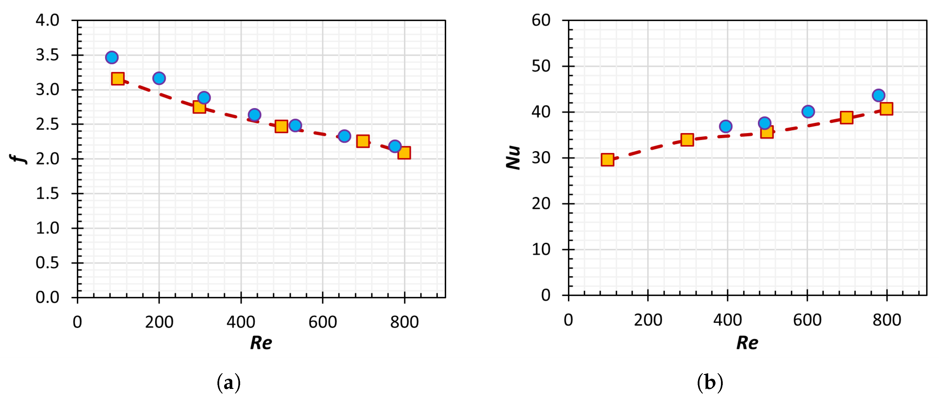
The numerical model was validated against the experimental data of Gherasim et al. [
25], who reported friction factor and hot-side Nusselt number measurements for a chevron-type plate heat exchanger over a range of Reynolds numbers. This dataset provides an appropriate reference for assessing the predictive capability of the present CFD framework under similar flow and thermal conditions.
Figure 3a compares the simulated Darcy friction factor with the experimental values for single-channel isothermal water flow. The CFD results follow the expected decreasing trend with Reynolds number and remain within approximately
of the experimental measurements across the examined range. This level of agreement indicates that the model captures the dominant viscous and geometric effects governing pressure losses in the channel.
Figure 3b presents the comparison of the predicted hot-side Nusselt number with the corresponding experimental data. The CFD predictions reproduce the observed increase in Nusselt number with Reynolds number and consistently fall within
of the measured values. The slight underprediction is consistent with the absence of experimental features such as port-induced maldistribution and side-edge bypass flow, which are known to affect local heat transfer.
Overall, the comparisons demonstrate that the CFD model reproduces the thermo-hydraulic behavior of the reference plate-channel configuration with sufficient accuracy for use in the subsequent analysis of flat, corrugated, and sinusoidal geometries.
3.3. Baseline Design and System Constants
The baseline configuration, summarized in
Table 1, represents a compact flat-plate heat exchanger designed to reflect the dimensional and operational constraints encountered in industrial thermal management systems. The geometry consists of ten stainless-steel plates, arranged with uniform channel spacing to maintain a compact footprint and sufficient flow area for heat removal. Stainless steel (SS 316L) was selected for its high thermal conductivity, corrosion resistance, and structural stability under elevated wall temperatures.
Deionized water was used as the working fluid owing to its high specific heat capacity, moderate viscosity, and availability. The thermophysical properties of both solid and fluid domains were temperature-dependent and evaluated at the mean bulk temperature representative of operation. The inlet conditions were chosen to yield Reynolds numbers within the laminar–transitional regime, where viscous and inertial effects coexist and strongly influence performance.
A preliminary parametric study for flat channels with inter-plate spacings of 3, 7, 10, and 15 mm quantified sensitivity of heat-transfer enhancement and pressure-drop behavior to channel confinement. The results indicate that a spacing of 7 mm achieved the most favorable thermo-hydraulic compromise, combining high wall heat flux with moderate pressure loss. This configuration was therefore adopted as the baseline for subsequent comparisons involving surface morphology.
3.4. Morphology Optimization
Surface-morphology optimization was conducted to evaluate the influence of corrugation geometry on convective enhancement and hydraulic behavior. Two families of surface features—chevron and sinusoidal corrugations—were selected due to their established relevance in compact plate heat exchangers and their contrasting flow modulation mechanisms [
4,
9]. All configurations were simulated under identical boundary conditions to ensure that performance differences originated solely from geometric effects.
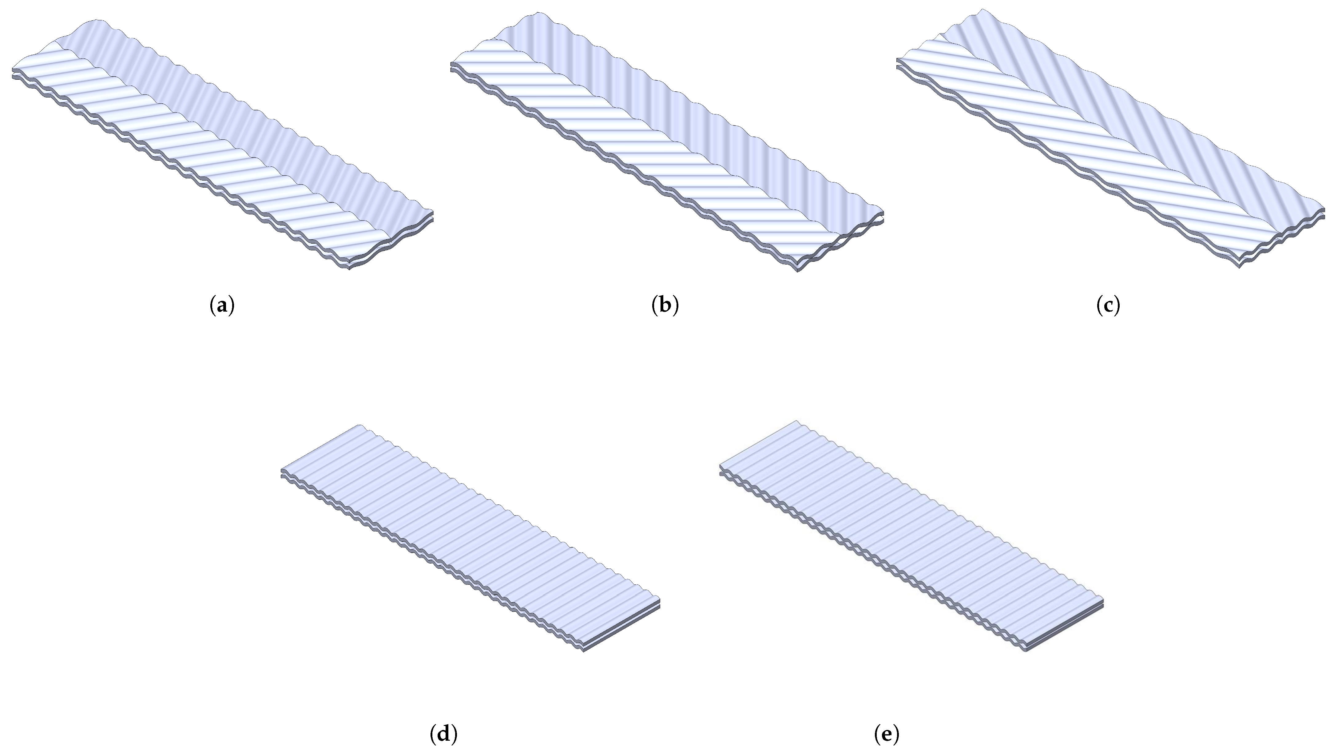
Chevron corrugations were modeled for three symmetric angular configurations: 60° (
Ch-60), 45° (
Ch-45), and 30° (
Ch-30), as presented in
Figure 4a–c. The corrugation angle is defined as the inclination of the plate embossing relative to the streamwise direction. The chevron angle directly controls the intensity and directionality of secondary flow structures formed at the intersections of converging and diverging channels. Lower angles (30°) induce moderate shear reorientation and limited recirculation, whereas higher angles (60°) promote strong impingement on the opposing plate, enhancing local mixing and boundary-layer disruption.
Sinusoidal corrugations were analyzed in two configurations: the in-phase arrangement (
Sin-in) shown in
Figure 4d and the 90° out-of-phase arrangement (
Sin-out) shown in
Figure 4e. The in-phase configuration denotes identical wall undulations on opposing plates, while the out-of-phase arrangement corresponds to a half-wavelength shift between the two surfaces, creating alternating contraction and expansion zones that modify cross-channel mixing. The in-phase design generates synchronized undulations that produce quasi-periodic acceleration–deceleration cycles along the channel. This promotes smooth boundary-layer reattachment and uniform inertial redistribution without sharp flow separation. The out-of-phase configuration introduces alternating contraction–expansion zones between opposing walls, enhancing cross-channel mixing and vortex pairing that improve interfacial transport.
Systematic variation of corrugation angles and phasing provides a complementary understanding of two enhancement modes: impingement-dominated (chevron-type) and oscillation-dominated (sinusoidal-type). This comparative analysis isolates the underlying flow physics responsible for thermal augmentation and hydraulic loss, offering quantitative insight into thermo-hydraulic tradeoffs in compact plate-type heat exchangers.
4. Results and Discussion
4.1. Parametric Study
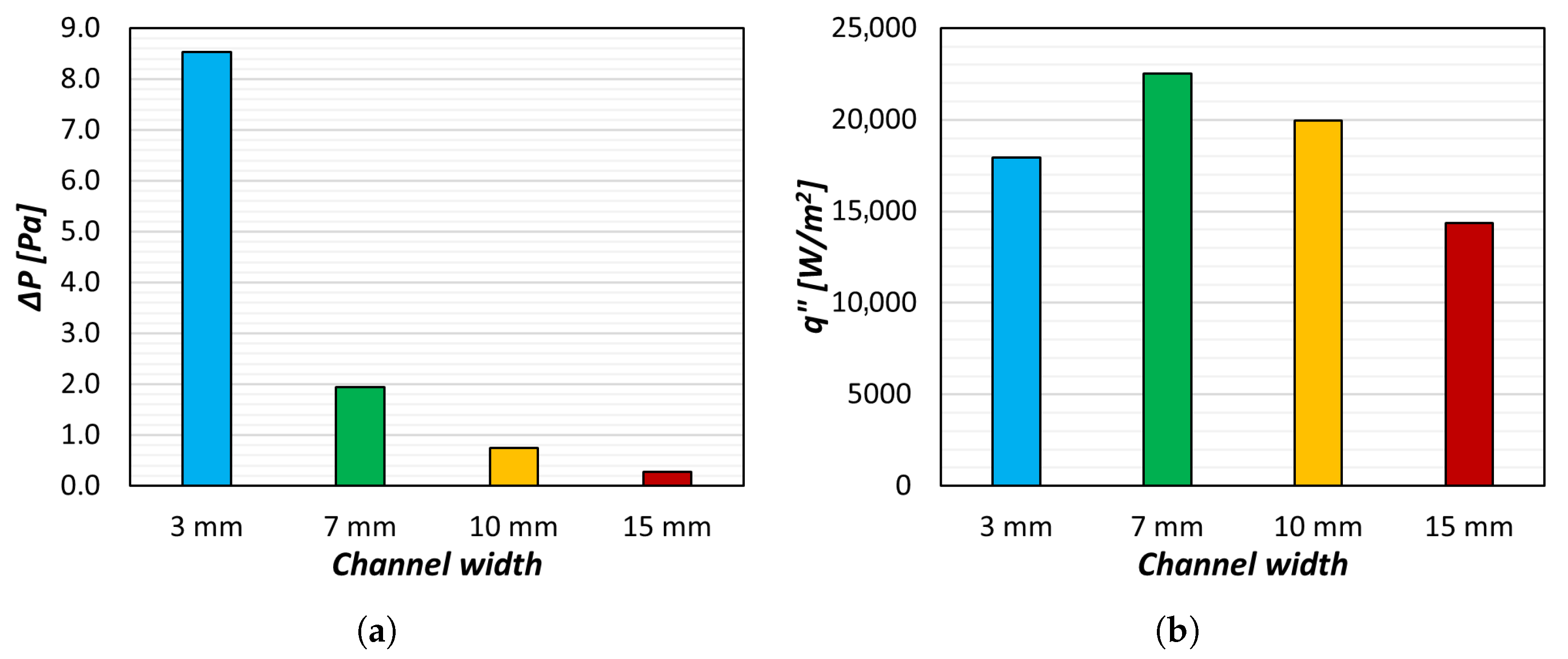
A baseline parametric investigation was conducted on the flat-plate configuration to quantify the influence of inter-plate spacing on thermo-hydraulic performance. The spacing was varied between 3 mm and 15 mm under identical boundary conditions. Two primary indicators—the channel pressure drop (
) and wall heat flux (
)—were evaluated to capture the interplay between frictional dissipation and convective transport in confined laminar flows (see
Figure 5a,b).
At the smallest spacing of 3 mm, the channel exhibited a pronounced hydraulic penalty ( Pa), caused by the reduced hydraulic diameter and intensified wall shear stresses. The narrow confinement increased near-wall velocity gradients and viscous dissipation, leading to elevated frictional losses. Although enhanced shear promoted local mixing and wall-normal motion, the overall thermal gain was modest ( W·m−2). This behavior results from premature boundary-layer merging, which suppresses inter-channel communication and stabilizes the core flow, limiting convective renewal and producing localized hot spots along the heated surface.
Increasing the spacing to 10 mm and 15 mm substantially reduced hydraulic resistance ( Pa and Pa, respectively) but also diminished heat-transfer performance ( W·m−2 and W·m−2, respectively). The decline in reflects reduced bulk velocity and a lower Reynolds number, resulting in weaker inertial transport and diminished boundary-layer interaction. Under these conditions, the flow approached a nearly fully developed laminar regime, where heat transfer is dominated by conduction and the wall-to-core temperature gradient increases linearly downstream.
Among all the configurations, the intermediate 7 mm spacing achieved the most favorable thermo-hydraulic balance, delivering the highest wall heat flux ( W·m−2) at a moderate pressure drop ( Pa), well within the design limit of Pa. This spacing represents an optimal balance between inertial and viscous forces: the flow retains sufficient momentum to thin the thermal boundary layer and sustain advective transport while avoiding excessive frictional losses. The regime remains partially developing, maintaining evolving velocity and temperature fields that yield elevated local Nusselt numbers before hydrodynamic stabilization occurs.
Consequently, the 7 mm configuration was selected as the reference geometry for subsequent morphology-optimization studies involving chevron and sinusoidal corrugations. These analyses build upon the established baseline to examine geometry-induced perturbations that further enhance convection while preserving overall thermo-hydraulic efficiency.
4.2. Thermofluidic Characterization
The thermofluidic behavior within the plate channels is governed by the evolution of streamwise velocity, wall heat flux, and near-wall temperature fields. These quantities reveal how each surface morphology modifies momentum transport, boundary-layer dynamics, and convective performance.
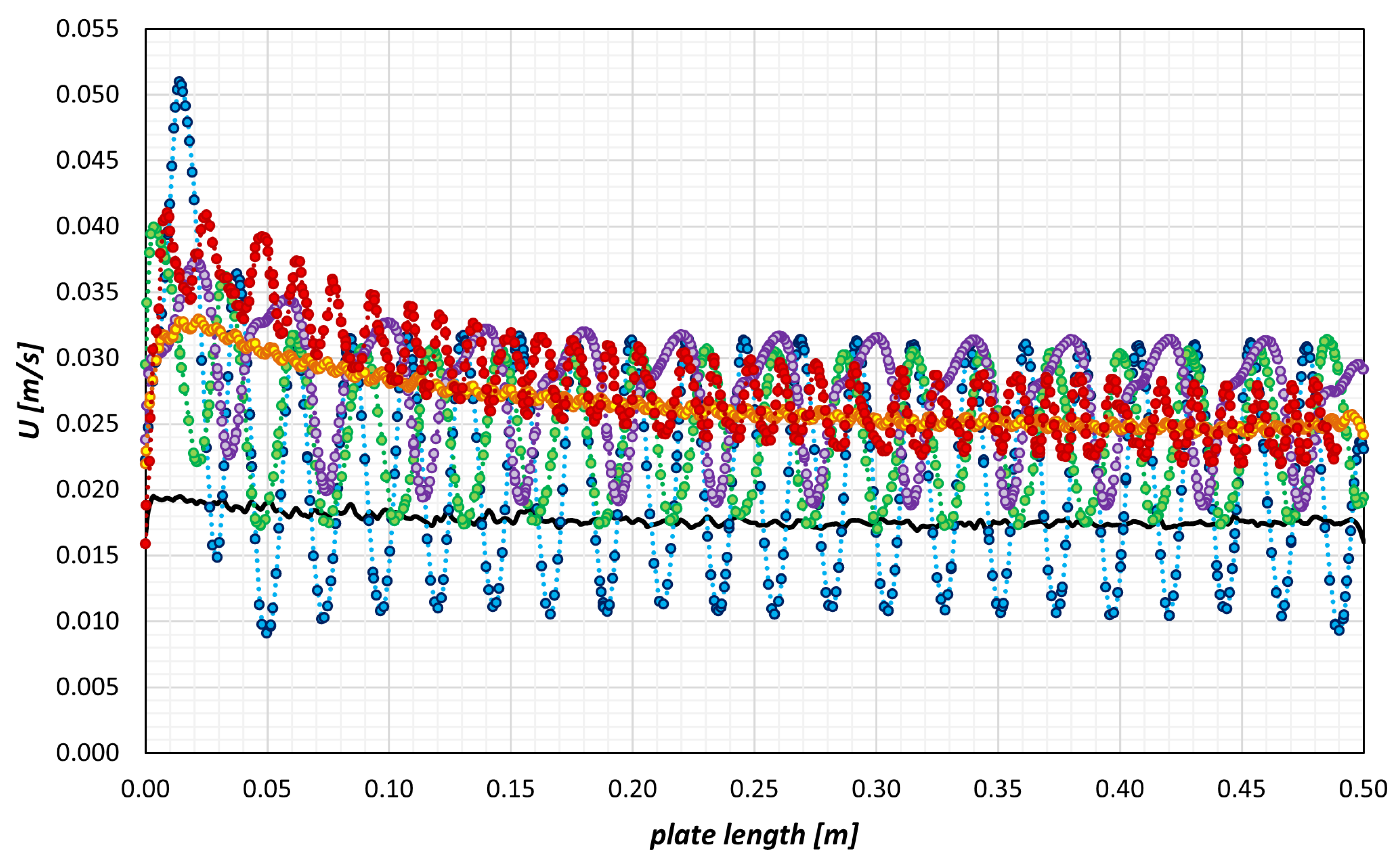
Figure 6 shows that the flat channel maintains an almost uniform streamwise velocity of approximately
with minimal fluctuation, reflecting diffusion-dominated behavior. Corrugated geometries introduce regular acceleration–deceleration cycles associated with periodic contraction and expansion. Among the chevron plates, the strongest modulation occurs for the
Ch-60 case, where local velocities exceed
, more than twice the flat-channel value. The mean velocity increases by roughly 30–50% for the three chevron angles, with the
Ch-30 configuration showing the smoothest oscillatory pattern due to weaker flow turning.
Sinusoidal morphologies generate smoother and more coherent oscillations. The Sin-out configuration exhibits the highest mean velocity (approximately ), driven by alternating contraction–expansion fields. The Sin-in case produces milder fluctuations, consistent with its symmetric geometry. In all cases, increased momentum near the wall indicates enhanced renewal of the boundary layer.
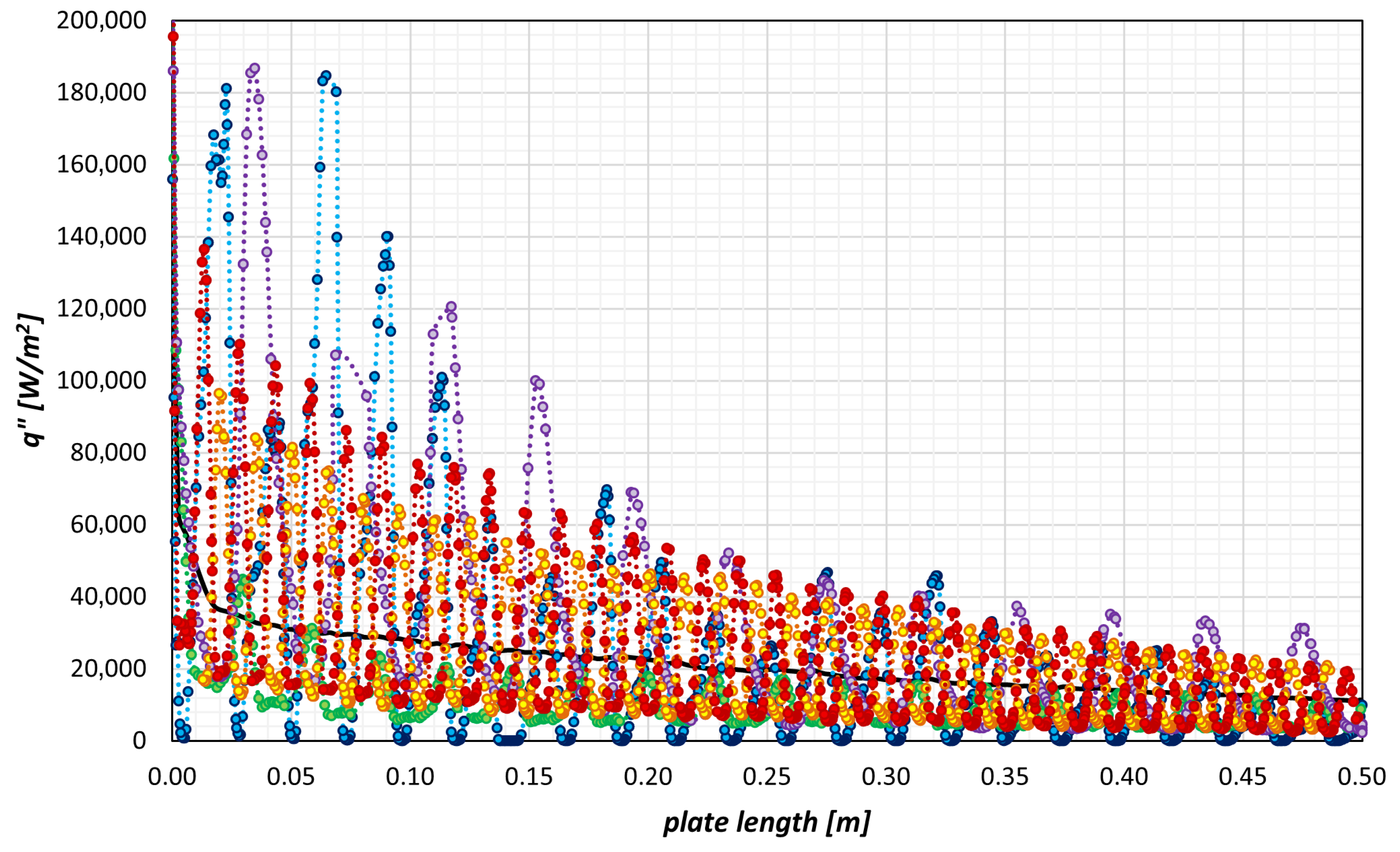
The wall heat-flux distribution in
Figure 7 mirrors these velocity trends. The flat plate exhibits monotonic decay of
due to continuous thermal boundary-layer growth. Corrugated geometries display periodic peaks whose amplitudes correlate with their velocity oscillations. The
Ch-60 chevron produces the largest fluctuations, with inlet-proximal peaks reaching (2.0–2.4) × 10
5 W·m
−2, approximately twice the flat-plate value. The
Ch-45 and
Ch-30 chevrons show progressively weaker modulation in line with reduced impingement intensity.
Averaged over the channel length, all corrugated geometries yield higher heat flux than the flat plate. Increases of approximately 6–12% are observed across the chevron and sinusoidal configurations. The Sin-out sinusoidal morphology exhibits slightly stronger peaks than the Sin-in case due to its alternating contraction–expansion behavior, although both remain smoother than the chevrons.
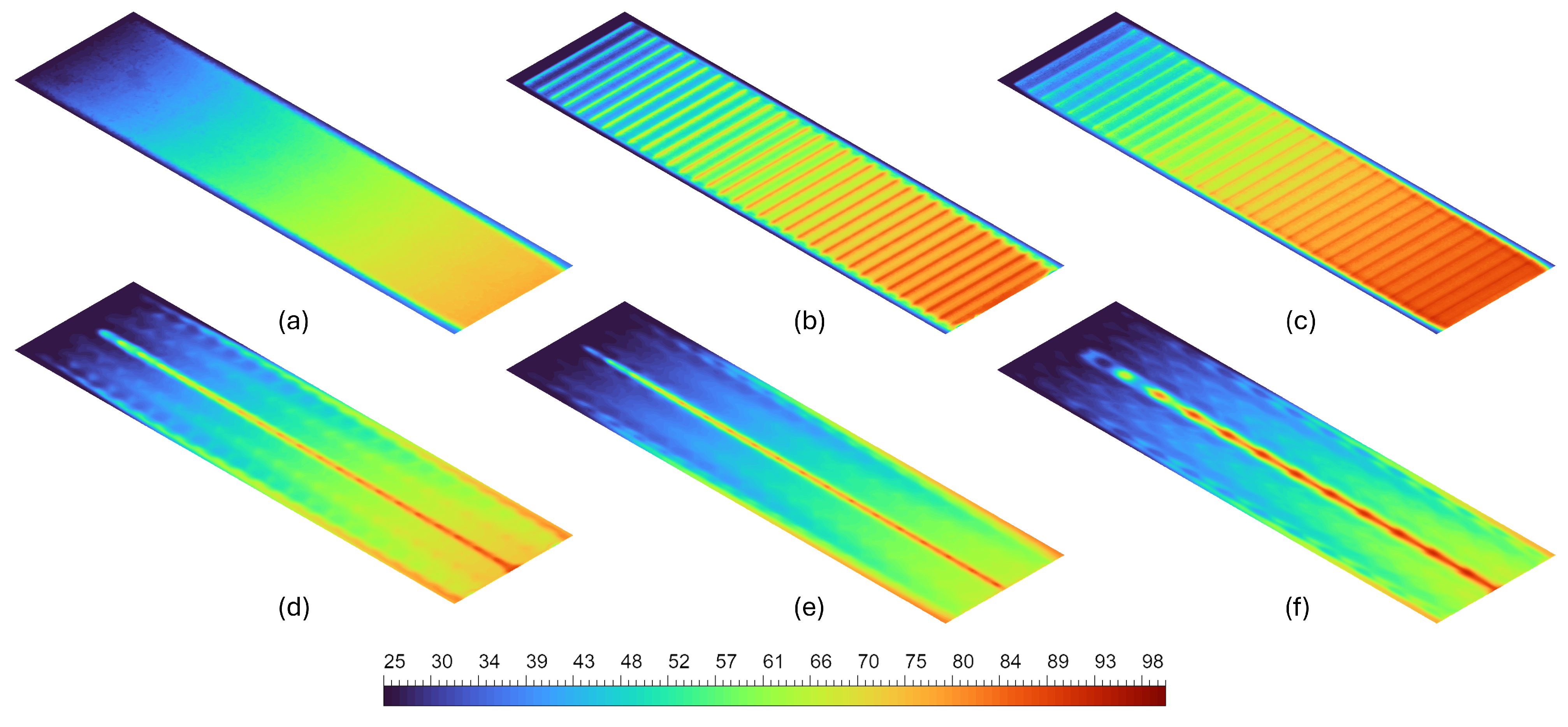
The temperature fields in
Figure 8 further substantiate these mechanisms. The flat channel shows uniformly spaced axial isotherms with minimal lateral distortion. The sinusoidal geometries generate controlled waviness: the
Sin-in design produces symmetric boundary-layer thinning, while the
Sin-out configuration enhances cross-stream mixing through alternating expansion and contraction.
Chevron plates produce the strongest thermal non-uniformity. The Ch-60 configuration generates clear streaks of alternating hot and cool regions corresponding to repeated boundary-layer removal by impingement on downstream crests. The Ch-45 and Ch-30 plates display progressively smoother temperature contours as vortex strength and mixing intensity decrease with angle.
The combined velocity, heat-flux, and thermal analyses indicate two distinct enhancement regimes. Chevron plates induce impingement-driven mixing, characterized by high-amplitude oscillations in velocity and heat flux, repeated boundary-layer disruption, and elevated hydraulic losses. These effects intensify with chevron angle. Sinusoidal geometries rely on inertia-driven oscillatory motion, producing smoother momentum and heat-flux modulation with substantially lower pressure penalties. Their behavior arises from curvature-induced flow redirection rather than abrupt impingement.
Collectively, these observations establish how different surface morphologies influence boundary-layer renewal, near-wall momentum transport, and overall convective behavior within compact plate channels.
4.3. Heat-Transfer Augmentation
The influence of surface corrugation on convective enhancement was evaluated using wall heat flux (
) and the local heat-transfer coefficient (
h). The comparative
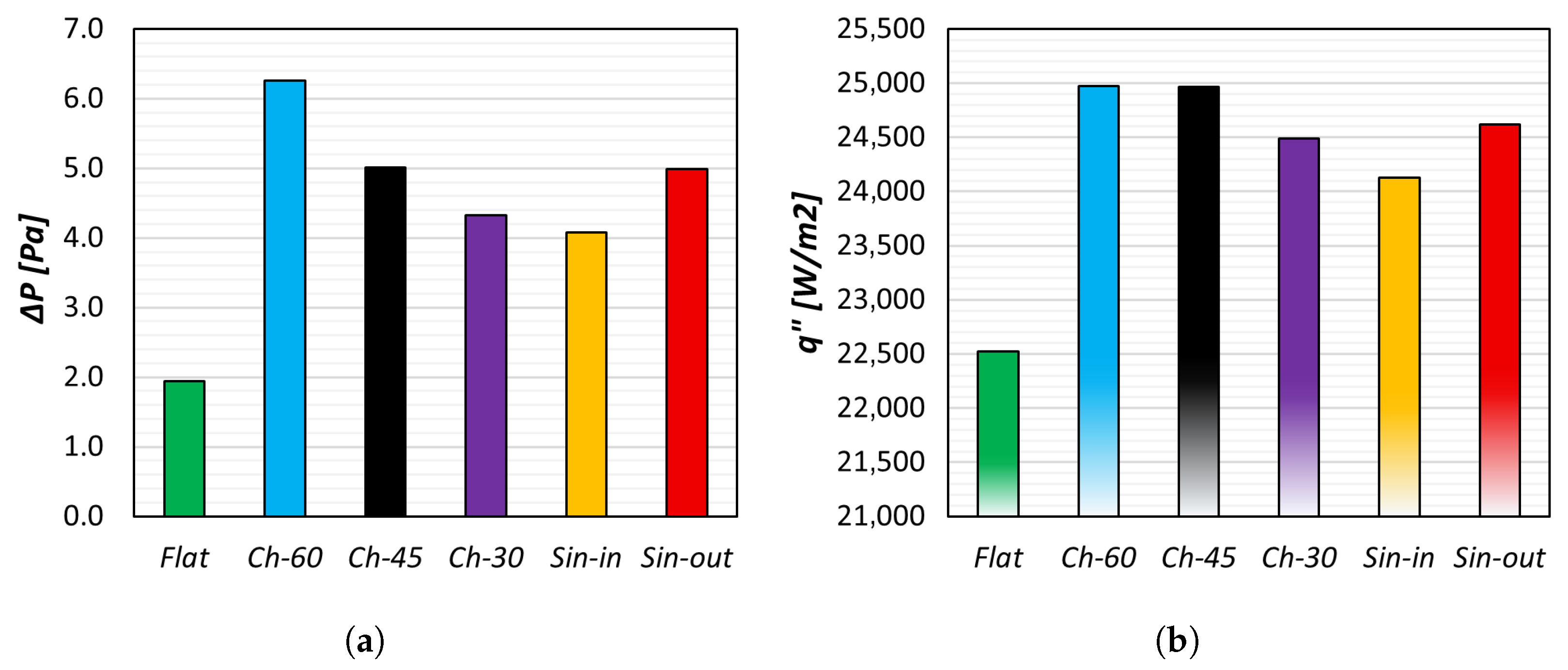
performance for all configurations is summarized in
Figure 9b. All corrugated geometries exhibited notable thermal improvement over the flat-plate baseline, confirming the effectiveness of geometry-induced flow modulation as a passive enhancement mechanism.
The flat channel, representing the fully developed laminar reference, produced a mean wall heat flux of
W·m
−2 and a corresponding heat-transfer coefficient of
W·m
−2·K
−1. The temperature distribution in
Figure 8a indicates a diffusion-dominated regime with minimal lateral energy transport. In contrast, the corrugated surfaces generated local flow acceleration, shear-layer detachment, and reattachment cycles that substantially increased wall-normal convective transport.
Among the chevron morphologies, the Ch-60 configuration achieved the highest enhancement, with W·m−2 and W·m−2·K−1, corresponding to an ∼11% improvement relative to the baseline. These global values are consistent with the streamwise heat-flux distributions, where the 60° chevron exhibits the largest local peaks and oscillation amplitudes along the plate length. The augmentation arises from oblique impingement of the inclined flow on downstream crests, which periodically removes the thermal boundary layer and renews wall–fluid contact. Alternating acceleration and stagnation zones further induce secondary vortices that intensify core-region mixing. However, this mechanism also increases frictional losses due to strong recirculation and local flow reversal.
As the chevron angle decreases to 45° and 30°, the flow becomes more streamwise-aligned, with weaker lateral swirl and reduced impingement intensity. Consequently, the heat-transfer coefficient remains elevated (–538 W·m−2·K−1) but approaches saturation as shear-driven effects stabilize. The Ch-30 design offers a more moderate balance between convective gain and hydraulic cost, maintaining elevated heat-transfer coefficients while reducing secondary motion and the associated pressure drop relative to the 60° chevron.
The sinusoidal configurations demonstrated comparable enhancement with lower hydraulic penalties. The in-phase arrangement (Sin-in) achieved W·m−2 (+7.1%) and W·m−2·K−1, while the out-of-phase design (Sin-out) produced W·m−2 (+9.3%) and W·m−2·K−1. The smooth curvature of these morphologies limits abrupt pressure-recovery zones and maintains flow continuity, allowing stronger advective transport without excessive turbulence generation. In the out-of-phase configuration, alternating contraction–expansion channels sustain gentle vortex shedding and continuous boundary-layer renewal, thereby enhancing thermal transport while preserving hydraulic efficiency.
From a thermofluidic standpoint, the enhancement mechanisms differ fundamentally. Chevron geometries are dominated by shear- and impingement-driven effects that maximize local heat transfer but incur higher . Sinusoidal geometries rely on inertia- and oscillation-driven mechanisms that yield smoother flow adaptation and superior global efficiency under constant pumping-power constraints. These results emphasize the importance of tuning geometric wavelength and amplitude to couple hydrodynamic and thermal fields effectively in compact plate-type heat exchangers.
4.4. Thermal Resistance–Compactness Tradeoff
Thermal resistance (
) and volumetric heat-transfer density (
) provide a complementary assessment of heat-exchanger performance. While
quantifies the overall resistance to heat flow,
represents the rate of heat transfer per unit channel volume. The Pareto representation in
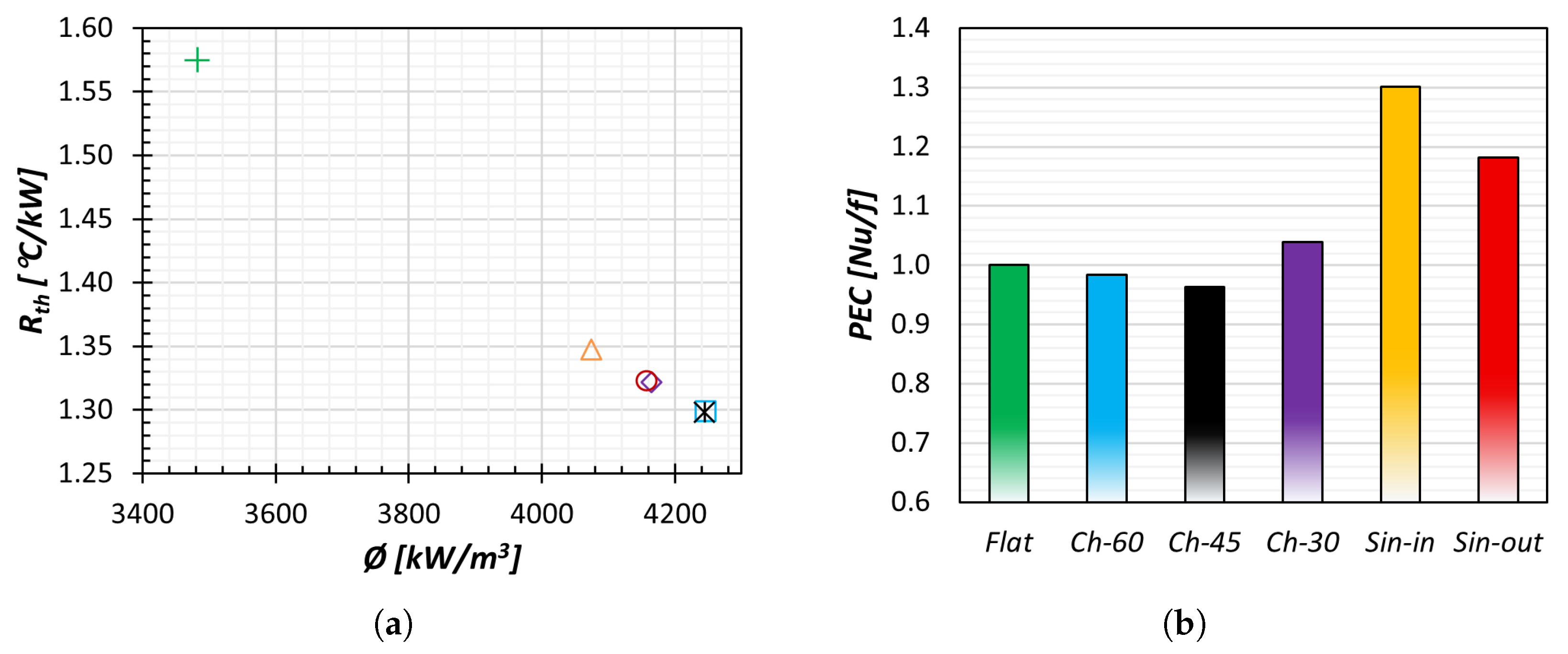
Figure 10a highlights the tradeoff between these metrics and enables a direct comparison of the geometric configurations.
The flat-plate channel occupies the upper-left region of
Figure 10a, with
and
kW·m
−3. This reflects boundary-layer thickening along the streamwise direction and limited cross-channel mixing, both of which constrain the effective heat-transfer area.
All corrugated geometries shift the operating point toward lower thermal resistance and higher compactness. The chevron configurations (Ch-30, Ch-45, and Ch-60) cluster in the lower-right region, with reduced to 1.30–1.32 °C·kW−1 and increased to approximately 4.16–4.25 MW·m−3. These changes arise from enhanced cross-channel advection and repeated disruption of the near-wall thermal layer associated with corrugation-induced secondary motion.
The sinusoidal surfaces similarly move toward the favorable region of the Pareto plane, with values of 1.32–1.35 °C·kW−1 and between and MW·m−3. The in-phase configuration is expected to induce smoother symmetric oscillatory flow redirection, while the out-of-phase arrangement introduces alternating acceleration fields; both mechanisms enhance convective transport relative to the flat channel, albeit with generally lower mixing intensity than the chevron geometries.
Overall,
Figure 10a illustrates the relative placement of the geometries on the performance map under the present operating conditions. Chevron plates yield the lowest thermal resistance and highest compactness but at the cost of higher pressure drop, whereas sinusoidal corrugations provide slightly milder improvements in
and
with smoother flow modulation and lower hydraulic penalties. These distinctions are particularly relevant in applications where allowable pressure drop or manufacturability constrains the choice of surface morphology.
4.5. Thermo-Hydraulic Tradeoff
While individual indicators such as or provide localized insight, the overall efficiency of a heat-transfer surface is captured by the Performance Evaluation Criterion (PEC). The PEC expresses the balance between normalized heat-transfer enhancement () and normalized frictional penalty () under constant pumping-power conditions, which represent a realistic design constraint in compact heat exchangers where improvements in convective transport must offset the associated hydraulic expenditure.
The comparative PEC results (
Figure 10b) show that chevron geometries achieve the strongest absolute thermal enhancement but suffer from high frictional penalties that diminish net efficiency. For
Ch-60 and
Ch-45, PEC values of approximately 0.98 and 0.96 indicate that the benefits of impingement-driven convection are nearly neutralized by viscous losses and wall shear. The
Ch-30 configuration performs slightly better (PEC
), reflecting a more moderate level of mixing that maintains enhanced heat transfer while reducing frictional penalties relative to the 60° chevron. As the chevron angle decreases, recirculation intensity weakens and the flow transitions from impingement-dominated to quasi-periodic reattachment, leading to a more uniform pressure distribution and more stable convective behavior.
Sinusoidal morphologies demonstrate superior thermo-hydraulic balance, achieving PEC values of ≈1.30 for the in-phase (Sin-in) and ≈1.18 for the out-of-phase (Sin-out) configurations, representing improvements of 30% and 18% over the flat-plate baseline, respectively. These gains arise from smooth acceleration–deceleration cycles generated by sinusoidal curvature, which enhance heat transfer through continuous inertial re-energization rather than abrupt shear-layer detachment. The gradual flow redirection suppresses stagnation zones, minimizes entropy generation, and maintains high convective efficiency per unit pressure drop. The in-phase geometry, in particular, achieves an optimal balance by sustaining periodic oscillations without large-scale flow separation, resulting in minimal energy dissipation per unit thermal gain.
From a system-design perspective, the PEC analysis confirms that geometric smoothness and controlled periodicity—rather than aggressive impingement—govern global efficiency in laminar-to-transitional compact channels. Corrugations that exploit inertial oscillations and streamline curvature may outperform conventional chevron patterns, particularly under constant volumetric flow or limited pumping-power constraints. This finding supports a broader design principle: thermo-hydraulic optimization in mini- and meso-scale exchangers should prioritize coherent flow and boundary-layer renewal over turbulence intensification to improve overall exergy utilization.
4.6. Design Implications and Structured Assessment
The comparative analysis across every configuration provides a unified understanding of how geometric modulation governs thermo-hydraulic performance in compact plate heat exchangers. The sequential methodology adopted in this study, beginning with channel-spacing optimization and progressing to surface-morphology refinement, enables systematic decoupling of scale-dependent effects. This structured approach provides a physically interpretable framework for performance-oriented design.
The parametric investigation demonstrated that inter-plate spacing exerts first-order control over the global tradeoff between viscous dissipation and convective transport. A spacing of 7 mm was identified as the critical equilibrium, where the flow retains sufficient inertia to sustain advective transport while avoiding excessive shear-induced pressure losses. This configuration therefore represents the most energetically efficient baseline for further morphological enhancement.
Building upon this reference, the introduction of corrugated morphologies revealed distinct thermo-hydraulic signatures determined by the underlying flow physics. Chevron geometries, characterized by sharp angular deflections, generate vigorous secondary flows and impingement zones, delivering substantial local heat-transfer enhancement but at the cost of elevated hydraulic penalties. In contrast, sinusoidal geometries induce gradual flow redirection and controlled oscillatory acceleration, facilitating boundary-layer renewal with significantly lower frictional losses. This contrast illustrates a useful principle of morphological optimization: geometries that maximize local turbulence do not necessarily yield the highest global efficiency.
Among all the designs, the in-phase sinusoidal configuration (Sin-in) emerged as the most balanced solution, achieving up to 30% higher thermo-hydraulic efficiency relative to the flat baseline, as measured by the PEC. Its smooth curvature is expected to reduce entropy generation, maintain coherent streamlines, and sustain efficient convective coupling under laminar–transitional flow regimes typical of compact exchangers. The out-of-phase variant, while slightly less efficient, promotes improved temperature uniformity and reduced thermal stratification, which are desirable attributes in applications emphasizing thermal homogeneity and fouling resistance.
The research outcomes of the present study show clear consistency with established findings in the literature. The trend of increasing heat transfer with decreasing channel spacing, accompanied by a corresponding rise in pressure drop, agrees with the behavior reported in [
3,
15]. Likewise, the enhanced secondary flows and higher frictional losses observed for chevron corrugations follow the trends documented in [
5,
6]. The smoother acceleration–deceleration cycles and lower hydraulic penalties exhibited by the sinusoidal geometries are also consistent with previous numerical and experimental investigations [
8,
9,
10]. These comparisons indicate that the present numerical predictions align well with the expected thermal hydraulic behavior of commonly analyzed plate heat-exchanger configurations.
The proposed framework provides a scalable methodology for rational heat-exchanger design. By sequentially assessing (i) hydraulic tuning at the channel scale, (ii) morphology-induced convective modulation, and (iii) system-level efficiency under constant pumping power, the workflow integrates fluid dynamics, heat transfer, and energy utilization within a unified assessment scheme. This physics-informed structure complements empirical design approaches by making the interaction between flow and thermal fields explicit in the design process.
Overall, the results reaffirm that optimal configurations in compact heat exchangers do not correspond to maximum heat-transfer rates alone but to the most favorable thermo-hydraulic equilibrium between augmentation and loss. In practical terms, such an equilibrium can support reduced pumping-power requirements and improved thermal compactness, which are desirable attributes for next-generation compact heat-exchanger systems.
5. Conclusions
A comprehensive thermo-fluidic investigation of plate heat exchangers was carried out using a sequential design framework that integrated baseline parametric analysis with surface-morphology optimization. The study elucidated the coupled influence of geometric confinement, flow hydrodynamics, and heat-transfer behavior, demonstrating how each design lever contributes to the global thermo-hydraulic balance. Channel spacing was identified as the dominant geometric variable governing this balance: narrow channels enhanced wall shear and viscous dissipation, producing large pressure penalties, while wider channels induced diffusion-dominated regimes with diminished convective activity. An intermediate spacing of 7 mm yielded the most favorable compromise, providing the highest wall heat flux ( W·m−2) under a moderate pressure drop ( Pa). This configuration therefore serves as a practical operating compromise between inertial transport and viscous resistance for the present conditions.
Surface-morphology optimization further revealed that corrugation topology dictates the underlying transport mechanisms. Chevron geometries, although effective at generating secondary vortices and disrupting boundary layers, imposed high frictional penalties due to repeated impingement and recirculation, resulting in marginal net efficiency gains. In contrast, sinusoidal morphologies produced smoother contraction–expansion cycles that facilitated periodic boundary-layer renewal through inertial oscillations while maintaining low hydraulic losses. These configurations enhanced and h by approximately 7–9%, increased PEC values by up to 30%, and reduced thermal resistance by 15–20%, with corresponding gains of 17–22% in volumetric heat-transfer density. The in-phase sinusoidal design emerged as the most effective configuration, combining smooth curvature, coherent flow organization, and comparatively low pressure penalties, achieving a PEC improvement of about 30% over the flat baseline.
Overall, the results indicate that optimal performance in compact heat exchangers is not achieved by maximizing heat flux alone but by attaining the most favorable thermo-hydraulic equilibrium, where convective enhancement is balanced against frictional losses under fixed pumping-power constraints. The structured framework developed herein provides a transferable methodology that couples geometric parameterization, flow physics, and energetic efficiency into a unified design process. Future extensions will focus on experimental validation of sinusoidal morphologies across multiple scales (mini-channel, plate module, and industrial prototypes) and on assessing manufacturability, material durability, and cyclic operational stability under realistic thermal–hydraulic conditions.