Perspective

Development and New Challenges of Sensorless Control for Permanent Magnet Synchronous Motors

1
School of Electrical Engineering and Automation, Harbin Institute of Technology, Harbin 150001, China
2
School of Electrical and Electronic Engineering, Harbin University of Science and Technology, Harbin 150001, China
*
Authors to whom correspondence should be addressed.
Energies 2026, 19(4), 1112; https://doi.org/10.3390/en19041112
Submission received: 30 December 2025 / Revised: 11 February 2026 / Accepted: 18 February 2026 / Published: 23 February 2026
(This article belongs to the Section F: Electrical Engineering)

Abstract

Permanent magnet synchronous motors (PMSMs) are widely used in various fields due to their high efficiency and power density. To further enhance reliability and reduce cost and volume, sensorless control techniques have been extensively investigated over the past few decades. This article provides a review of major sensorless control methods, categorizing them into low-speed and high-speed methods. Virtual frequency methods, saliency-based methods, and model-based methods, along with their developments, are analyzed and compared. In addition, application-oriented analysis, implementation insights, as well as the challenges and future development trends are discussed at the end of the article.

1. Introduction

Permanent magnet synchronous motors (PMSMs) have been widely used in fields such as electric vehicles, ship propulsion, and home appliances due to their compact structure, high power density, fast dynamic response, etc. [1,2,3]. In the field-oriented control (FOC) system for PMSM drives, accurate rotor position and speed is essential for high-performance control. Thus, position sensors such as an encoder or a resolver are usually installed on the rotor shaft. However, mechanical position sensors, along with their cables and interfaces, are considered potential failure points that threaten system reliability, particularly for motors operating in extreme environments such as those with high temperatures, complex electromagnetic fields, and severe vibrations. Moreover, eliminating these sensors can significantly reduce overall cost, which has long been an industrial pursuit. To address these issues, sensorless control algorithms have been developed to replace traditional sensors by providing online estimations of speed and position. In addition, some control strategies that do not rely on position information can also be regarded as broad-sense sensorless control.
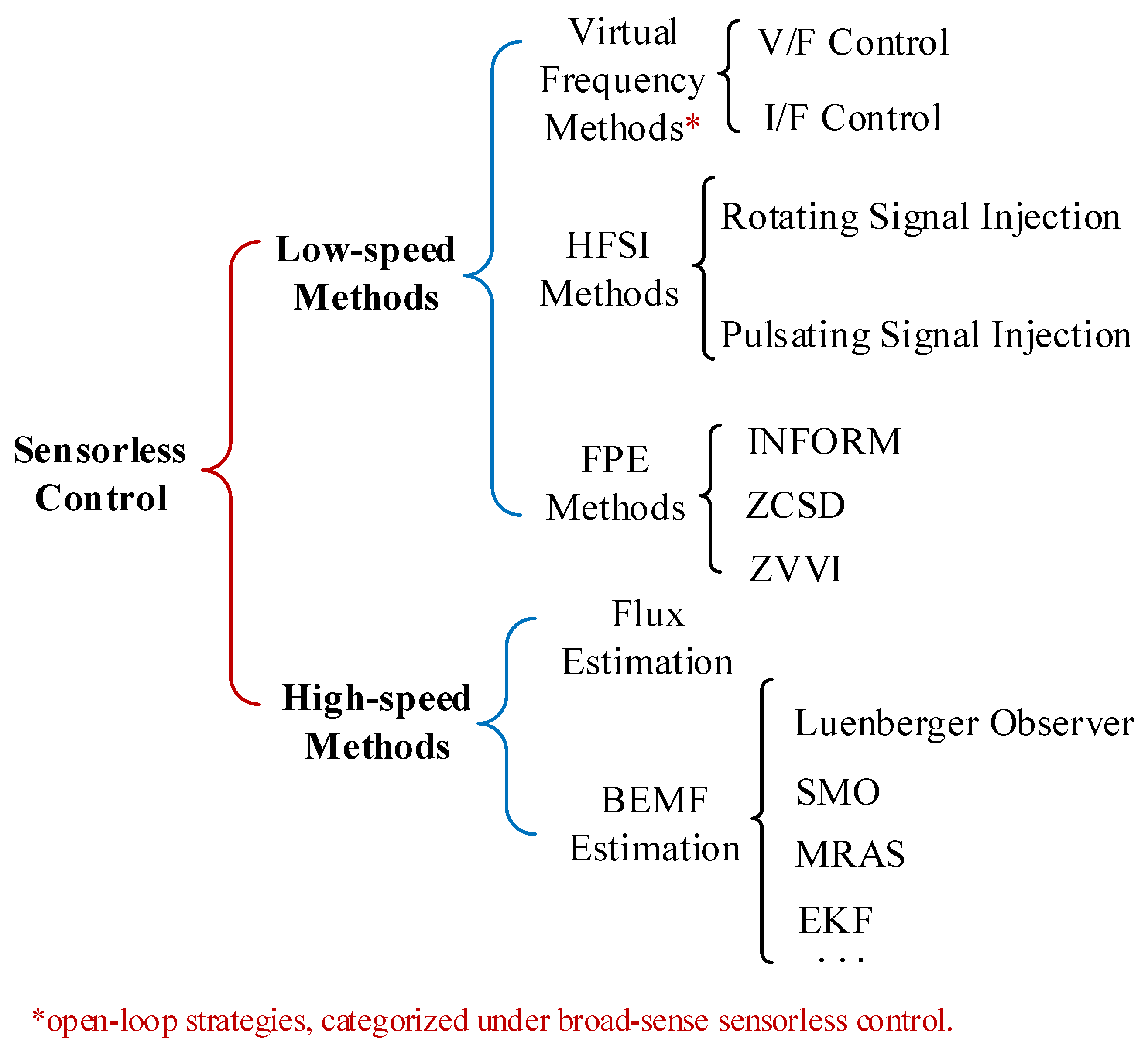
Sensorless control emerged in the 1990s and has been extensively studied over the past decades. The existing sensorless methods can be primarily classified according to their applicable speed range into high-speed methods and low-speed methods, as shown in Figure 1. It is noteworthy that the boundary between these regions is not absolute. Based on the existing research and industry practice, the low-speed region is often considered to be below 5–10% of the rated speed, while high speed covers the medium to rated speed range and above.
The low-speed sensorless methods include virtual frequency methods [4,5,6,7,8], high-frequency signal injection (HFSI) methods [9,10,11,12,13,14,15,16,17,18,19,20,21,22,23,24,25,26,27,28,29,30,31,32,33,34,35,36,37], and fundamental PWM excitation (FPE) methods [38,39,40,41,42,43,44,45]. The virtual frequency methods are essentially open-loop control strategies. Unlike conventional closed-loop methods for speed and position estimation, the virtual frequency method directly generates voltage vectors based on an artificially given virtual position. This characteristic of being independent of position information enables it to be classified as a broad-sense sensorless strategy. HFSI methods and FPE methods achieve position estimation at low speeds by using closed-loop strategies to track rotor saliency, which originates from the d-q axis magnetic reluctance asymmetry [10]. Specifically, the HFSI method achieves saliency tracking by applying a sufficient high-frequency excitation, while the FPE method relies on measuring current responses caused by different voltage space vectors applied to the motor.
The high-speed methods, also known as the model-based methods, extract rotor position and speed by estimating the flux or back electromotive force (BEMF) related to the fundamental wave of the motor [46,47,48,49,50,51,52,53,54,55,56,57,58,59,60,61,62,63,64,65,66]. To achieve accurate estimation, various types of observers based on modern control theory have been studied. Many works focus on sliding-mode observers (SMOs) due to their inherent robustness and simplicity [67,68,69,70,71,72,73,74,75,76,77,78,79,80,81,82,83,84]. In addition, linear Luenberger observers are also widely used [85,86,87,88,89]. To further enhance noise immunity and estimation accuracy, the extended Kalman filter (EKF) is introduced and refined in [90,91,92,93,94,95,96,97,98,99]. In parallel, model reference adaptive systems (MRASs) offer an alternative framework for position estimation by enforcing the convergence of a reference model and an adjustable model [100,101,102,103,104,105]. However, due to factors such as inverter nonlinearity, modeling errors and signal-to-noise ratio, the model-based methods may suffer from performance degradation or even failure, particularly under zero/low speeds [106,107,108,109,110,111,112,113,114,115,116,117,118,119,120,121,122,123,124,125,126,127,128,129,130,131,132,133,134,135,136,137,138,139,140,141,142,143,144,145,146,147,148]. To achieve full-speed-range sensorless control, hybrid strategies incorporating both low-speed and high-speed methods are commonly adopted. Correspondingly, switching strategies between different methods in the transition region need to be investigated [149,150,151,152,153,154,155].
Today, sensorless control has approached maturity through efforts in both industry and academia. The research focus of sensorless control algorithms is shifting from principal exploration to performance optimization, aiming to enhance their applicability across various operating conditions. This article reviews existing sensorless control algorithms and their recent developments. In addition, based on the core requirements of different application scenarios, the applicability and performance tradeoffs of various methods are analyzed, aiming to provide a reference for technology selection in engineering practice. Finally, the challenges and trends in this field are discussed.
The rest of the article is organized as follows. The second and third sections introduce the low-speed and high-speed sensorless methods, respectively. The fourth section provides an application-oriented analysis and implementation insights, along with a discussion of the challenges and future development trends. Finally, the fifth section concludes the article.

2. Low-Speed Sensorless Control Methods

2.1. Virtual Frequency Methods

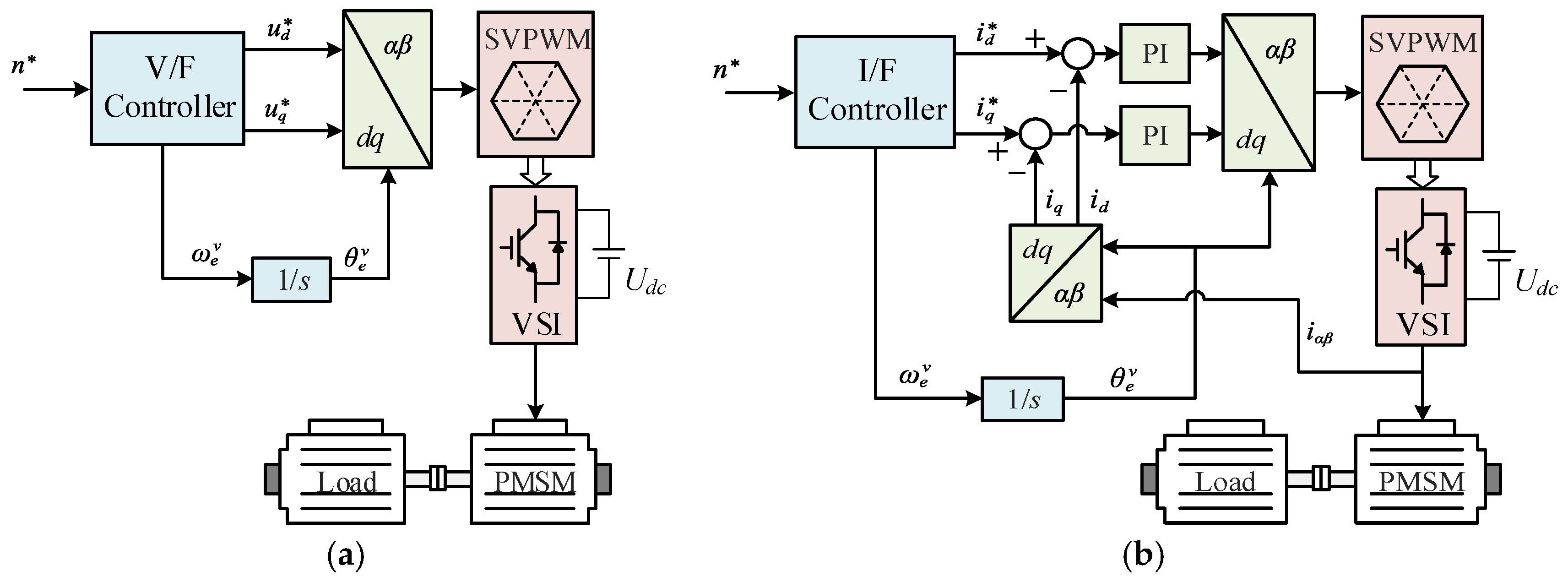
The virtual frequency methods do not detect the actual rotor position, which generate the voltage vector based on a virtual angle obtained by integrating a given frequency [4,5]. Figure 2 shows the control diagrams for the two common virtual frequency methods, including V/F and I/F control techniques. As an effective and easily implementable control strategy, the virtual frequency method can operate without a position sensor. Therefore, it can be regarded as a form of sensorless control.
As shown in Figure 2a, V/F control is an open-loop control for both speed and current (n* is the speed reference). Therefore, V/F control has a poor load-carrying capacity and anti-interference ability. Compared with V/F control, as can be seen from Figure 2b, I/F control achieves closed-loop current control by providing a current reference (i d*, i q*) with specific amplitude and frequency ( ω e v ). The motor is driven to the given speed based on the self-balancing characteristic of the power angle. However, the self-balancing characteristic limits the load-carrying capacity and is sensitive to disturbances. Thus, I/F control is unsuitable for low-speed steady-state control. Thus, it is often employed as a start-up strategy for PMSMs. Once the rotor speed is established, the system can switch to a model-based method.
When switching to the model-based method, the mismatched current vector may lead to a loss of synchronization. To address the problem, research has been carried out from different aspects. Reference [6] proposes a transition method for the switching process. Based on the error between the estimated position and reference value, an integrator is employed to adjust the reference of q-axis current, thereby achieving a smooth transition between different algorithms. In [7], a speed–position–current tracking controller is proposed to serve as the middle layer, which achieves a high acceleration rate. In [8], traditional I/F control is combined with a predictive algorithm to enhance anti-interference performance during the start-up process. However, in applications that require higher starting torque, accurate rotor position is necessary and the virtual frequency method will not be applicable.

2.2. HFSI Methods

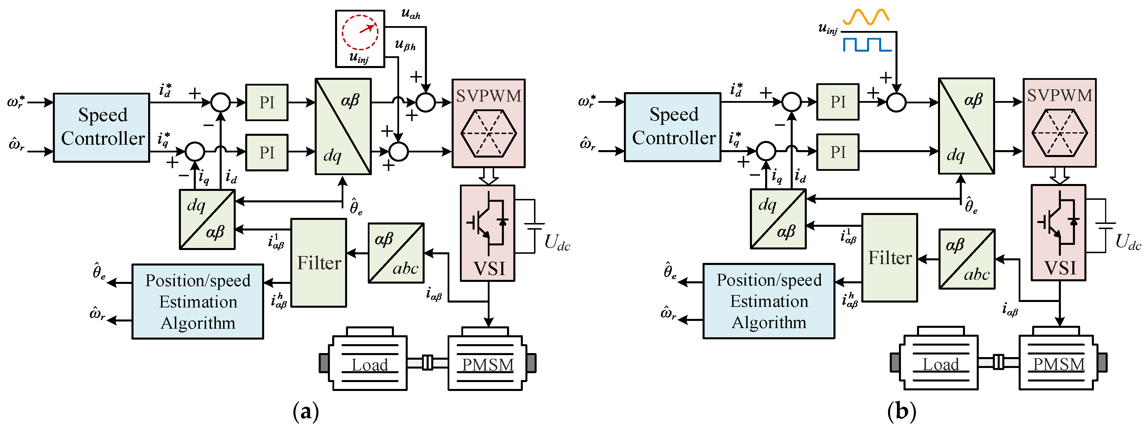
The high-frequency signal injection method is an effective sensorless control scheme in the zero/low-speed region for PMSMs. The HFSI methods are based on the saliency characteristic of the motor and extract rotor position from the high-frequency response caused by high-frequency voltage [9,10]. For the interior PMSM (IPMSM), the asymmetry of the rotor magnetic circuit results in different d-q axis inductances, which is known as structural saliency. The d-q axis inductances of the surface-mounted PMSM (SPMSM) are the same. However, when a specific voltage is applied, it will exhibit saturation saliency due to magnetic circuit saturation. Figure 3 shows the block diagrams of the HFSI methods, where ωr* is the speed reference. According to the applied reference frame, high-frequency injection methods can be divided into two categories: rotating signal injection in the stationary reference frame [11,12,13,14] and pulsating signal injection in the synchronous reference frame [15,16,17,18].

2.2.1. PMSM HF Model

Considering that the injection frequency ωh is much higher than the fundamental frequency ωe of the motor, the voltage drops on resistance, and variables associated with ωe can be neglected. The high-frequency model of the PMSM in the d-q frame is derived as
u d h u q h = L d 0 0 L q p i d h i q h
where udh, uqh, idh and iqh are high-frequency voltages and currents in the d-q frame; Ld and Lq are d-q axis inductances; and p is the differential operator.
Transforming (1) to the α-β frame yields
u α h u β h = Σ L + Δ L cos 2 θ e Δ L sin 2 θ e Δ L sin 2 θ e Σ L Δ L cos 2 θ e p i α h i β h
where uαh, uβh, iαh and iβh are high-frequency voltages and currents in the α-β frame; θe is the roto position; ∑L = (Ld + Lq)/2 and ΔL = (LdLq)/2.

2.2.2. Rotating Signal Injection

As shown in Figure 3a, a rotating voltage vector (3) is injected into the voltage reference in the α-β frame.
u α h u β h = V i n j cos ( ω h t ) sin ( ω h t )
where Vinj is the magnitude of the injected voltage vector.
The HF current response in the α-β frame can be derived as
i α h i β h = I s p sin ( ω h t ) + I s n sin ( ω h t + 2 θ e ) I s p cos ( ω h t ) I s n cos ( ω h t + 2 θ e )
where Isp and Isn are the magnitudes of the positive-sequence and negative-sequence components, respectively.
It can be seen that the negative-sequence component includes the rotor position. In the signal process, the HF current is obtained through a band-pass filter and transformed to negative-sequence rotating reference frame, yielding
i d h i q h n = I s p sin ( 2 ω h t ) + I s n sin ( 2 θ e ) I s p cos ( 2 ω h t ) I s n cos ( 2 θ e ) n
After low-pass filtering, the rotor position can be obtained through an arctangent function as
θ e = 1 2 arctan L P F ( i d h ) L P F ( i q h )
For the rotating signal injection, the application in the α-β frame allows direct rotor position estimation in theory, eliminating the need for an additional position tracker. However, the use of filters inevitably introduces errors and delays. In addition, the frequency of the injected signal is usually less than one tenth of the pulse width modulation (PWM) frequency, ensuring that the high-frequency current response can be sampled to obtain a complete cycle.

2.2.3. Pulsating Signal Injection

Figure 3b shows the block diagram of a pulsating signal injection. The HF signal is injected into the estimated d-axis. Thus, the initial rotor position is needed and position tracking is achieved by eliminating the error between the actual d-axis and the estimated one. According to the form of the injected signal, the pulsating signal injection can be further divided into a pulsating sinusoidal injection (7) and pulsating square-wave injection (8).
u d h u q h = V i n j cos ( ω h t ) 0
u d h u q h = ± V i n j 0
The HF current response can be derived as
i d h i q h = K Σ L Δ L cos 2 θ ˜ e Δ L sin 2 θ ˜ e u i n j d t
where K is the amplitude coefficient and θ ˜ e = θ e θ ^ e , θ ^ e is the estimated rotor position.
According to (9), the error of the rotor position can be obtained through extracting the envelope of the HF current. By inputting the error into a position observer, the estimated position and speed can be further obtained.
In practical applications, the frequency of the injected signal is typically set between several hundred Hz and several kHz [17], which fundamentally limits the bandwidth of the position observation [18]. Furthermore, signal processing components such as LPFs, BPFs, and demodulators introduce additional delay and phase lag. To enhance the dynamic response, a pulsating square-wave injection is preferred because square-wave signals are easy to generate and their frequency can reach up to the PWM switching frequency [19]. Additionally, solutions such as filterless carrier separation [20], fast time-domain demodulator [21] and PID-type Luenberger position observer [22] have also been proposed. However, considerable work remains for the HFSI methods to achieve dynamic performance comparable to that of mechanical sensors.
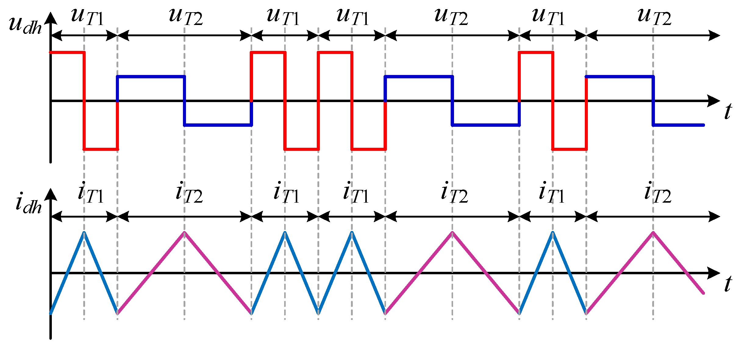
Another critical issue in HFSI applications is the acoustic noise caused by high-frequency signals, which is unacceptable for noise-sensitive applications such as household motors and underwater propulsion. Common methods for noise reduction include increasing the injection frequency [23], reducing the amplitude of the injected signal [24], and adopting random injection [25,26,27,28]. Reference [25] modifies the injected voltage signal from a fixed frequency to a varying frequency, spreading the acoustic energy on a frequency band, thereby reducing the peak level of noise. Figure 4 shows the HF voltage and corresponding current response waveforms with a random-frequency injection method, where the injected signal randomly switches between two specific frequencies [26]. According to power spectral density (PSD) analysis in [27], the randomized high-frequency injection method achieves a smoother distribution of the current PSD, thereby effectively mitigating high-frequency noise [28].
In addition, the influence of non-ideal factors such as inverter nonlinearity, cross-coupling saturation, and multiple saliency effect on the HFSI should be taken into consideration to achieve more accurate position estimations [29,30,31].

2.2.4. Magnetic Polarity Identification

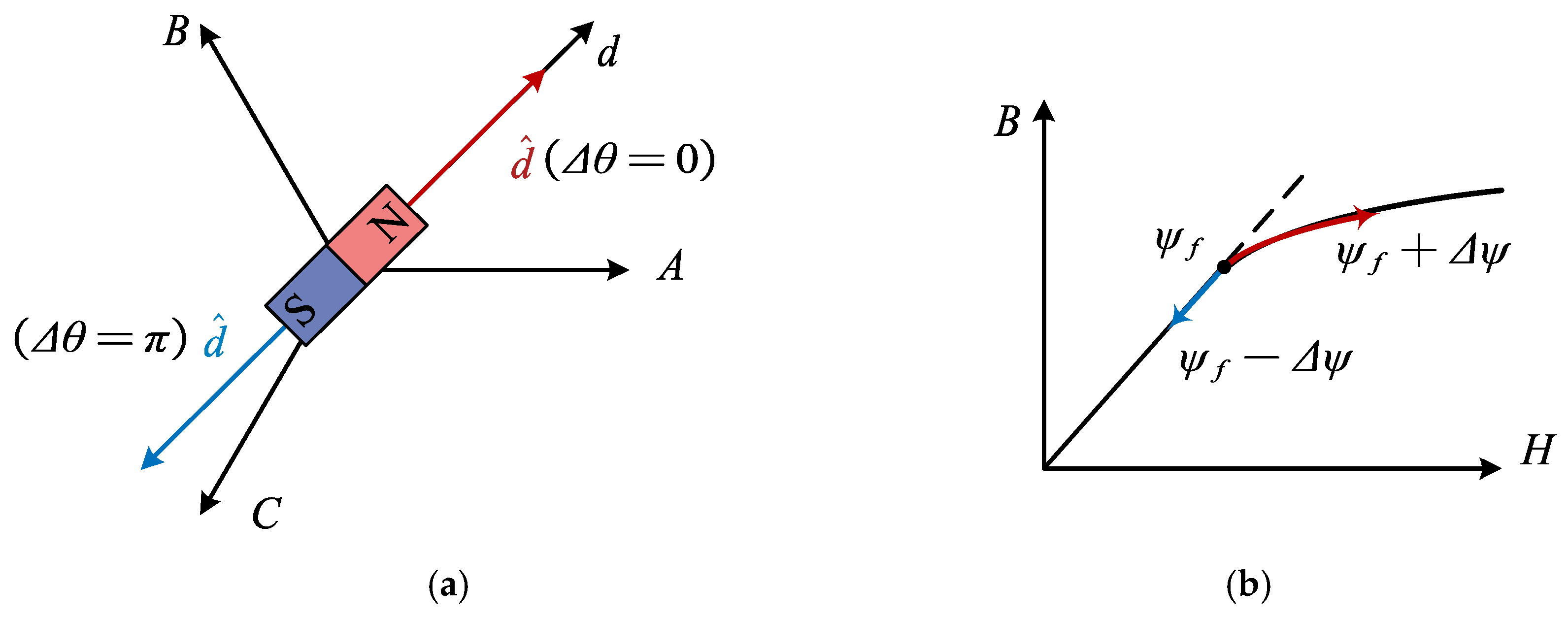
For saliency-based methods, the position information varies periodically at twice the fundamental frequency. Therefore, the obtained rotor position does not contain polarity information, which may result in the estimation error of π, as shown in Figure 5a. Figure 5b shows the nonlinear saturation characteristic of the stator core, which can be utilized for polarity identification [32]. Positive d-axis current increases the saturation level of the stator core, while negative current reduces saturation. By injecting different test signals to the d-axis, the polarity can be identified through the response of the injected signal, such as the dual pulse injection method [33]. As reported in [34], by comparing the amplitude of the current responses of two opposite voltage pulses, the pulse with a higher amplitude represents the actual d-axis direction. In addition, the second harmonic-based methods are studied in [35,36,37]. The 2nd harmonics in the HF current response or HF zero-sequence voltage response can be utilized to determine polarity.

2.3. Fundamental PWM Excitation Methods

Compared with the HFSI methods, the FPE methods directly use the PWM signal as the excitation source, without the need for additional signal injection. Thus, the FPE methods will not cause additional high-frequency noise. The rotor position is obtained by sampling the current change rate generated by the voltage vectors. Existing FPE methods include indirect flux detection by online reactance measurement (INFORM) [38,39,40], the zero-sequence current derivative (ZSCD) measurements method [41,42,43] and the zero voltage vector injection method (ZVVI) [44,45]. Due to the fact that the FPE method detects the current change rate multiple times within one PWM cycle, traditional continuous sampling cannot meet the requirements of high-frequency current measurements. Therefore, complex high-speed and high-precision current sampling circuits and specially designed modulation signals are necessary, which are unfriendly to low-cost control systems. The characteristics of the major low-speed sensorless methods are summarized in Table 1.

3. High-Speed Sensorless Control Methods

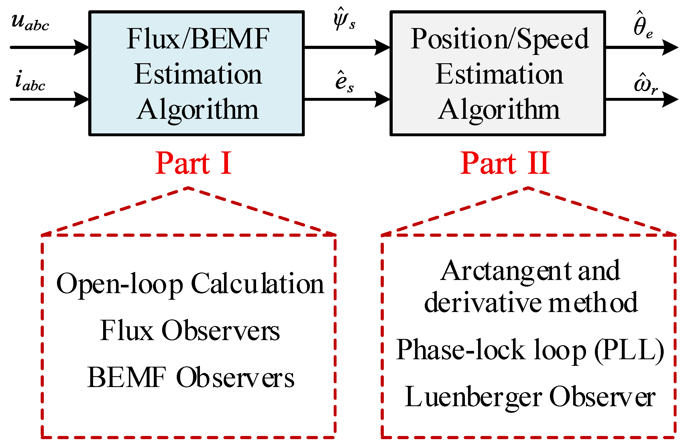
The low-speed methods discussed in the previous section have been proven effective and applied in the industry. However, due to adverse effects such as torque ripple, limited dynamic response, and acoustic noise, these methods are recommended to be used only in the zero/low-speed range. With the increase in speed, switching to model-based methods is a commonly adopted strategy. Since the rotor position information is included in the flux or back EMF, the model-based method generally consists of two stages: flux or back-EMF estimation, position and speed extraction, as shown in Figure 6. In the first stage, both flux and back EMF can be obtained through open-loop calculation and close-loop observation. The former is directly calculated from the model equation, and the latter estimates the state variables through an observer. In the second stage, the position and speed can be obtained through an open-loop arctangent function and differential operation or close-loop phase-lock loop (PLL) and Luenberger observer [46,47,48,49,50,51].

3.1. Flux or Back-EMF Estimation

3.1.1. Flux-Based Methods

Sensorless control based on flux linkage estimation has been widely used [52,53,54,55,56]. It operates by estimating the flux linkage produced by the permanent magnets and then extracting the rotor position from this estimated flux.
In the stationary frame, the stator flux linkage of SPMSM can be expressed as
ψ α ψ β = L α 0 0 L β i α i β + ψ m α ψ m β
ψ m α ψ m β = ψ f cos θ e sin θ e
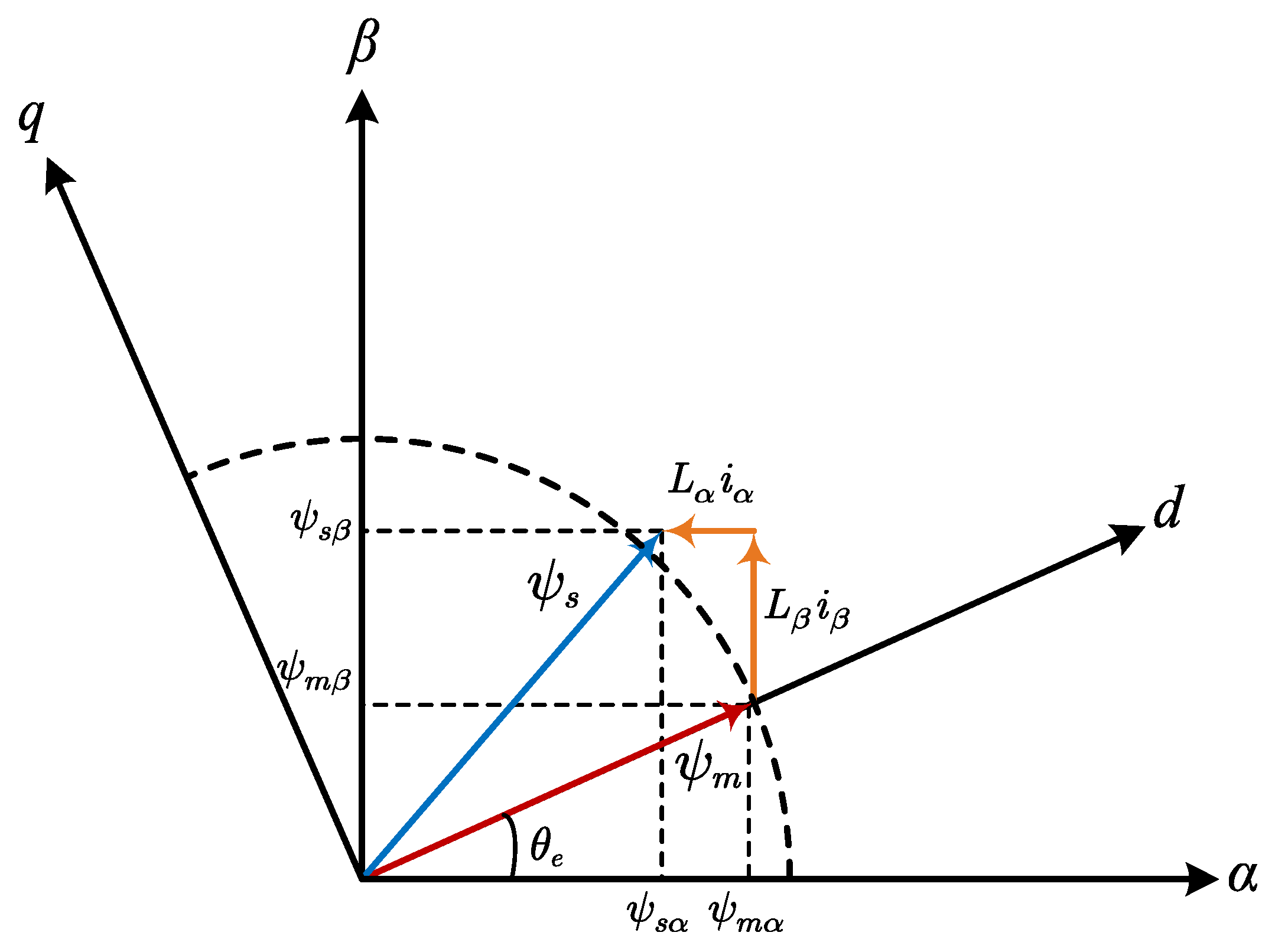
where ψα and ψβ are stator flux linkage, ψ and ψ are PM flux linkages, ψf is the magnitude of the PM flux linkage and Lα = Lβ = Ls is the phase inductance of the SPMSM. The phasor diagram of the flux linkage is shown in Figure 7, where ψs and ψm represent synthetic stator flux and PM flux, respectively.
Generally, the stator flux linkage is the integral of the back EMF, as
ψ α = u α R s i α   d t ψ β = u β R s i β   d t
Then, the rotor position can be obtained as
θ e = arctan ψ m β ψ m α = arctan ψ β L s i β ψ α L s i α
The block diagram of flux-based sensorless control is presented in Figure 8.
For an IPMSM, its stator flux satisfies
ψ α ψ β = Σ L + Δ L cos 2 θ e Δ L sin 2 θ e Δ L sin 2 θ e Σ L Δ L cos 2 θ e i α i β + ψ f cos θ e sin θ e
The inductances in the α-β frame are coupled with the rotor position, which increases the difficulty of estimating the PM flux linkage. To address this problem, [57] proposed the concept of an active flux, which unifies a salient-pole motor as a virtual non-salient machine.
The active flux is defined as
ψ a = ψ f + L d L q i d
The stator flux of IPMSM can be rewritten as
ψ α ψ β = L q 0 0 L q i α i β + ψ a cos θ e sin θ e
Similarly, the rotor position can be obtained as
θ e = arctan ψ β L q i β ψ α L q i α
However, calculating flux through an integrator is highly susceptible to non-ideal factors such as core saturation, temperature drift, and initial value mismatch. This causes errors to accumulate progressively, culminating in system instability. Hence, the use of a pure integrator is typically avoided.
In [58], the pure integrator is replaced with LPF to enhance the robustness against DC offset. Due to the phase lag introduced by the LPF, a flux observer with delay compensation is employed in [59]. Further, a second-order generalized integrator (SOGI)-based flux observer is introduced in [60], featuring improved performance in both harmonic suppression and system robustness. In [61], a nonlinear flux observer is proposed, which employs the magnitude of the PM flux for feedback correction. The practicality has been demonstrated. Based on this, [62] has improved the mechanism of error correction for the nonlinear flux observer. Dynamic response and estimation accuracy are further improved. In [63], a high-order nonlinear adaptive observer is constructed. It features a nonlinear update law for parameters and employs higher-order sliding-mode terms to correct estimation errors, achieving an improved dynamic response.

3.1.2. Back-EMF-Based Methods

In addition, back-EMF-based sensorless control algorithms have also been extensively studied [64,65,66]. As the rotor rotates, the back EMF is generated in the stator winding and is proportional to the speed. The back EMF of SPMSM can be expressed as
e α e β = u α u β R s + p L s 0 0 R s + p L s i α i β = ω e ψ f sin θ e cos θ e
The rotor position can be obtained as
θ e = arctan e α e β
For IPMSMs, the concept of an extended back EMF was proposed in [65]. The extended back EMF of an IPMSM is defined as
e α e β = u α u β R s + p L d ω e L d L q ω e L d L q R s + p L d i α i β = E e x sin θ e cos θ e
E e x = L d L q ω e i d p i q + ω e ψ f
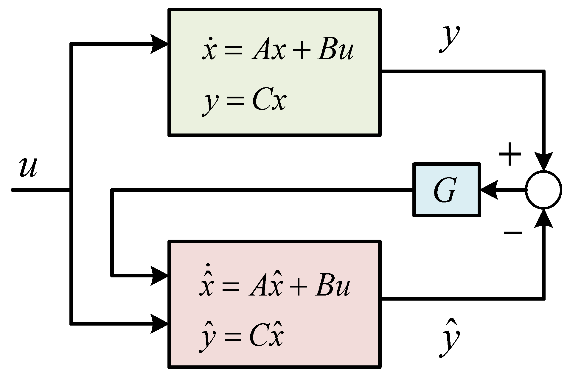
During motor operation, the back EMF is difficult to measure directly and is therefore estimated from the measurable stator voltage and current. The estimated back EMF can be directly calculated based on (20), but closed-loop observers are more favored due to their high accuracy and robustness. Figure 9 illustrates the general block diagram of an observer [66]. Assuming the controlled object is given by
p x = A x + B u y = C x
where x is the state variable, u is the excitation, and y is the measured response. The estimation model can be described as
p x ^ = A x ^ + B u + G y C x ^ y ^ = C x ^
where the variable with the symbol “^” represents the estimated value. G is the feedback gain matrix, which has various forms.
For the back-EMF observers, the estimation model is generally established based on the fundamental model of the controlled PMSM. The current error between the estimated state and sampling value is used for model correction under a specific control law. When the error converges to zero, the estimated state can reflect the system state. To this end, various control laws and state variable selections create a variety of observers, including the sliding-mode observer, full-order/reduced-order state observer, extended state observer (ESO), model reference adaptive system, extended Kalman filter and so on.
(1)
Sliding-Mode Observer
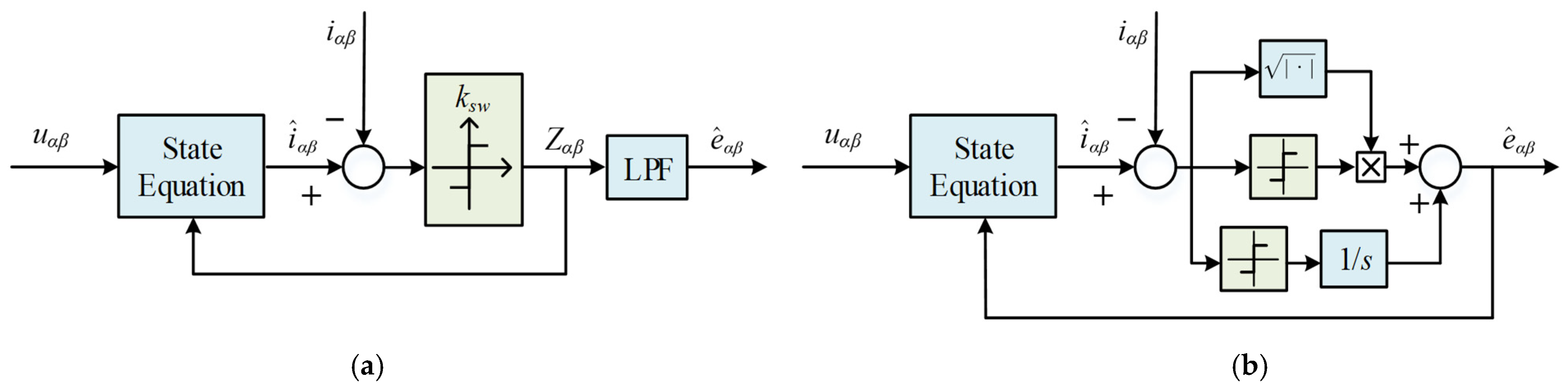
The SMO has been widely studied due to its simple structure and strong robustness [67,68,69,70,71,72]. The key to the SMO lies in the variable structure control. As a nonlinear observer, it typically introduces a signum function as a correction term. The discontinuous gain switching depends entirely on the sign of the estimation error. When the error reaches zero, the back EMF, which is treated as an unknown disturbance, can be fully compensated by the output of the signum function. The LPF value of this output thereby provides an estimate of the back EMF. The block diagram of SMO is present as Figure 10a.
However, the high-frequency switching of the signum function also leads to the undesirable chattering problem, manifesting as high-frequency noise in the estimated back EMF. As the chattering originates from the inherent discreteness of the signum function, the smoother saturation function and sigmoid function are used to weaken chattering in [73,74,75,76,77]. Inside the boundary layer, the gain continuously changes with error, which can effectively suppress chattering. A comparative study in [78] indicates that the sigmoid function offers a better performance for chattering suppression compared with two alternative switching functions. Nevertheless, the selection of the boundary layer involves a critical tradeoff between the estimation performance and the level of chattering [79]. In [80], an adaptive gain control law is proposed. The SMO gain varies with the speed range, and the chattering is suppressed. Furthermore, the high-order SMO is also designed for chattering suppression [81]. By selecting both the back EMF and the current as state variables, the analysis in [48] shows that the required sliding-mode gain only needs to be greater than the maximum estimation error of the back EMF. This allows for a lower gain setting, which effectively mitigates the chattering phenomenon.
Another type of higher-order SMO, known as the super-twisting SMO [82,83], is illustrated in Figure 10b. The super-twisting SMO is based on the super-twisting algorithm (STA), and the control law is defined as
Z S T A = k S T A 1 i ˜ α β 1 2 sign i ˜ α β + ξ S T A d d t ξ S T A = k S T A 2 sign i ˜ α β
where ZSTA is the output of control law. kSTA1 and kSTA2 are the STA gains. The integral part in (24) has a suppressing effect on chattering, but the performance of STA-SMO is affected by STA gains. The relevant parameter design methods can be found in [84]. However, due to the involvement of discontinuous dynamics, it is difficult to achieve ideal parameter selection.
(2)
Luenberger Observer
The Luenberger observer, functioning as a linear observer, achieves state tracking through an error feedback coefficient matrix. This matrix is designed through pole placement or optimization methods [85,86,87,88,89].
The state equation of the Luenberger observer is expressed as
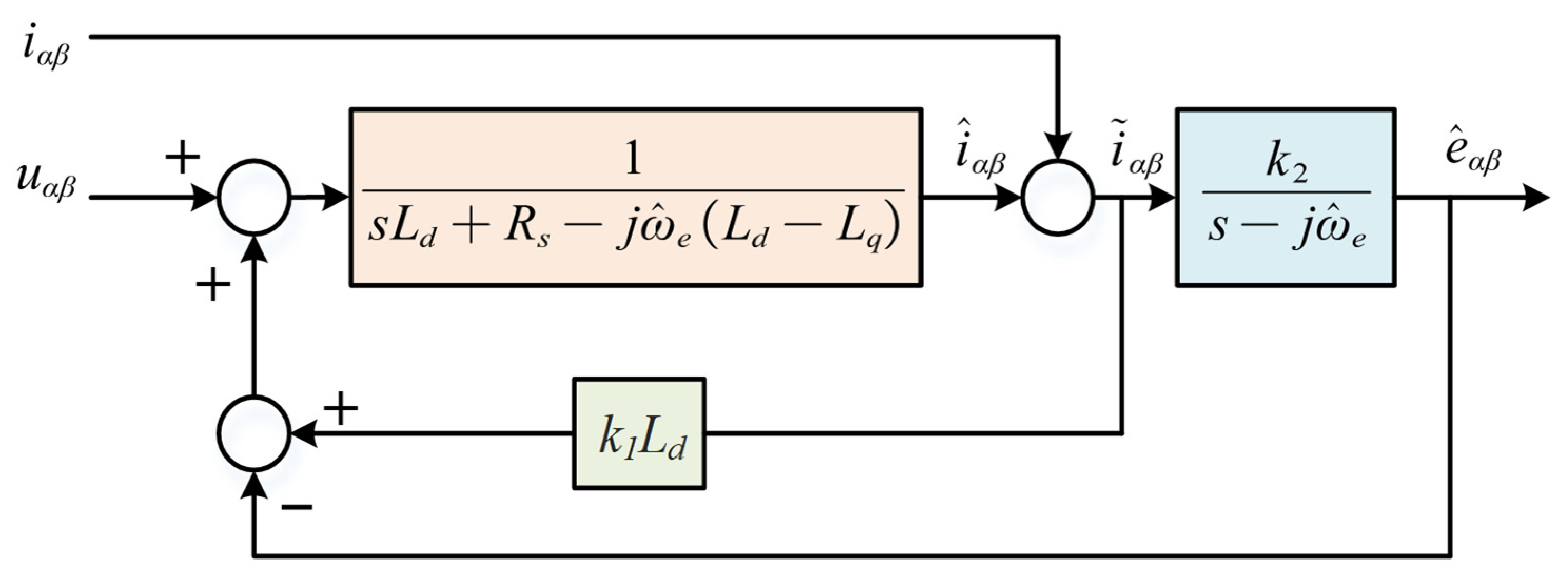
s i ^ α β = R s L d + j ω ^ e L d L q L d i ^ α β + 1 L d u α β e ^ α β + k 1 i ^ α β i α β s e ^ α β = j ω ^ e e ^ α β + k 2 i ^ α β i α β
where k1 and k2 are gains of feedback. The gain design can be found in [86], and the block diagram of the Luenburger observer is present as Figure 11.
The transfer function between the estimated and actual back EMF is
G c s = e ^ α β s e α β s = = k 2 s j ω ^ e s L d + R s j ω ^ e L d L q k 1 L d + k 2
According to (26), the observer exhibits a second-order low-pass characteristic, which consequently provides a continuous and smooth output. This avoids the chattering issue of sliding-mode-based observers. Reference [88] systematically compares reduced-order and full-order back-EMF observers for sensorless drives. The reduced-order observer is easier to tune, while the full-order observer offers superior robustness against parameter variation and noise.
(3)
Extended Kalman Filter
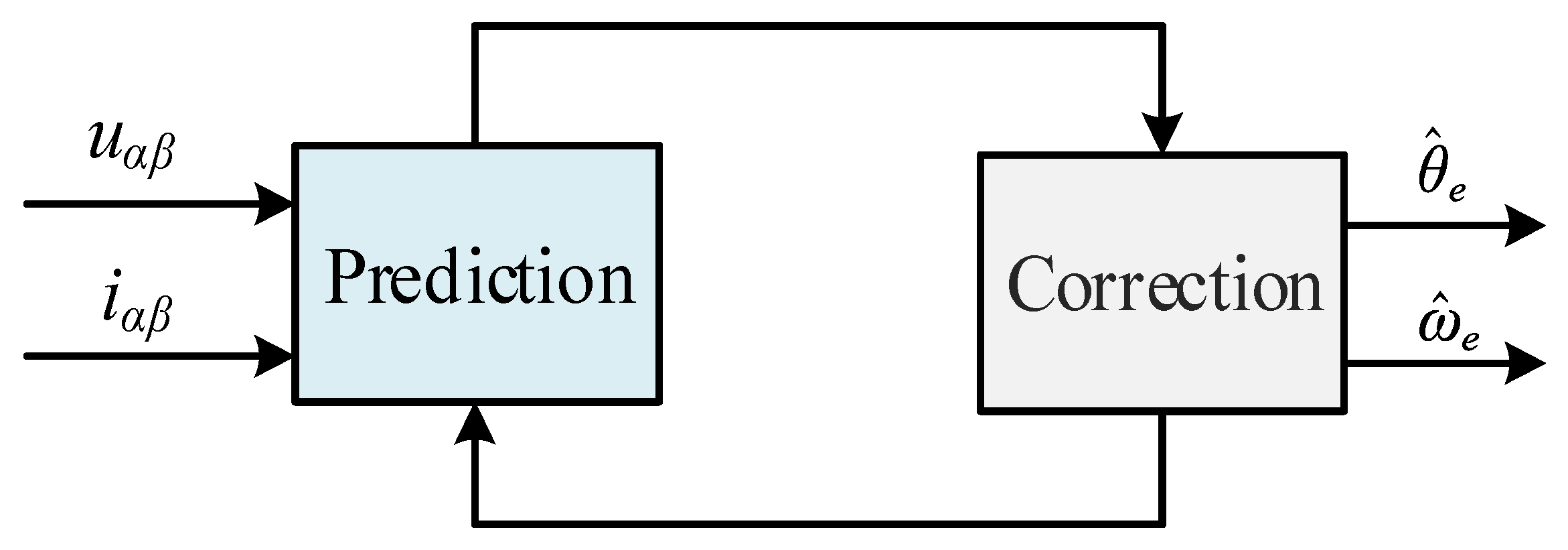
The extended Kalman filter is a recursive computational method for nonlinear estimation [90,91,92]. The EKF algorithm consists of two parts: prediction and correction, as illustrated in Figure 12. It primarily predicts the system states by utilizing the system model and reference voltage information, then corrects these predictions using the measured current signal. Applications of the EKF for PMSM sensorless control are documented in [93,94,95,96,97,98,99]. Due to its prediction–correction mechanism, the EKF can effectively suppress the influence of system noise and disturbances, exhibiting strong robustness [96].
In [97], the full-order form of the EKF is presented. The selection of the EKF covariance matrices can refer to [93]. It is observed that the recursive algorithm involves operations with fourth-order matrices, which imposes high demands on the computational capability of processors. Considering that some states can be directly obtained from measurements, the reduced-order EKF has been investigated in [98,99]. This reduces the model complexity and further decreases the computational load of the system.
(4)
Model Reference Adaptive System
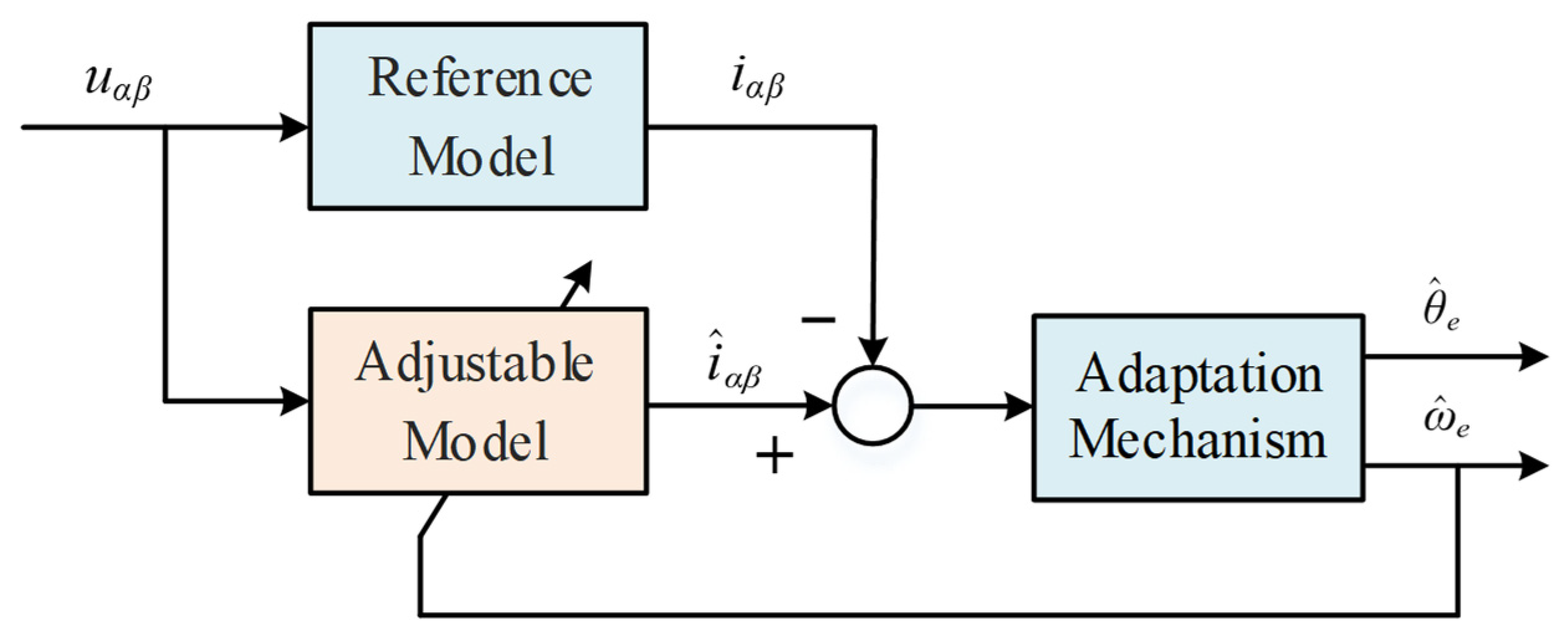
In the MRAS algorithms, the physical motor with known parameters serves as the reference model, while a parametric motor model constitutes the adjustable model [100,101,102,103,104,105]. The current error between these two models is fed back to the adjustable model through a specific adaptive law. The output of the adaptive law is typically the rotor position or speed. Although the back EMF is not directly observed, it is implicitly reconstructed during the speed identification process. The block diagram of the MRAS method is shown in Figure 13.
Based on the conventional MRAS, ref. [102] introduces an improved adaptive law that enables simultaneous estimation of both speed and load torque, thereby improving disturbance rejection and dynamic response. To address parameter variations, the MRAS algorithm in [103] incorporates online estimations of both resistance and flux. Additionally, the grey wolf optimizer algorithm is utilized to adjust the parameters of the adaptive law. In [104], an MRAS algorithm based on a finite position set is proposed. It utilizes a model predictive algorithm to replace the PI regulator in the adaptive law, thus offering a novel design approach. Reference [105] considers the impact of high-speed operation on the MRAS algorithm. A discrete-time MRAS algorithm based on the second-order Taylor expansion is proposed, which improves the discretization accuracy and stability of the algorithm.
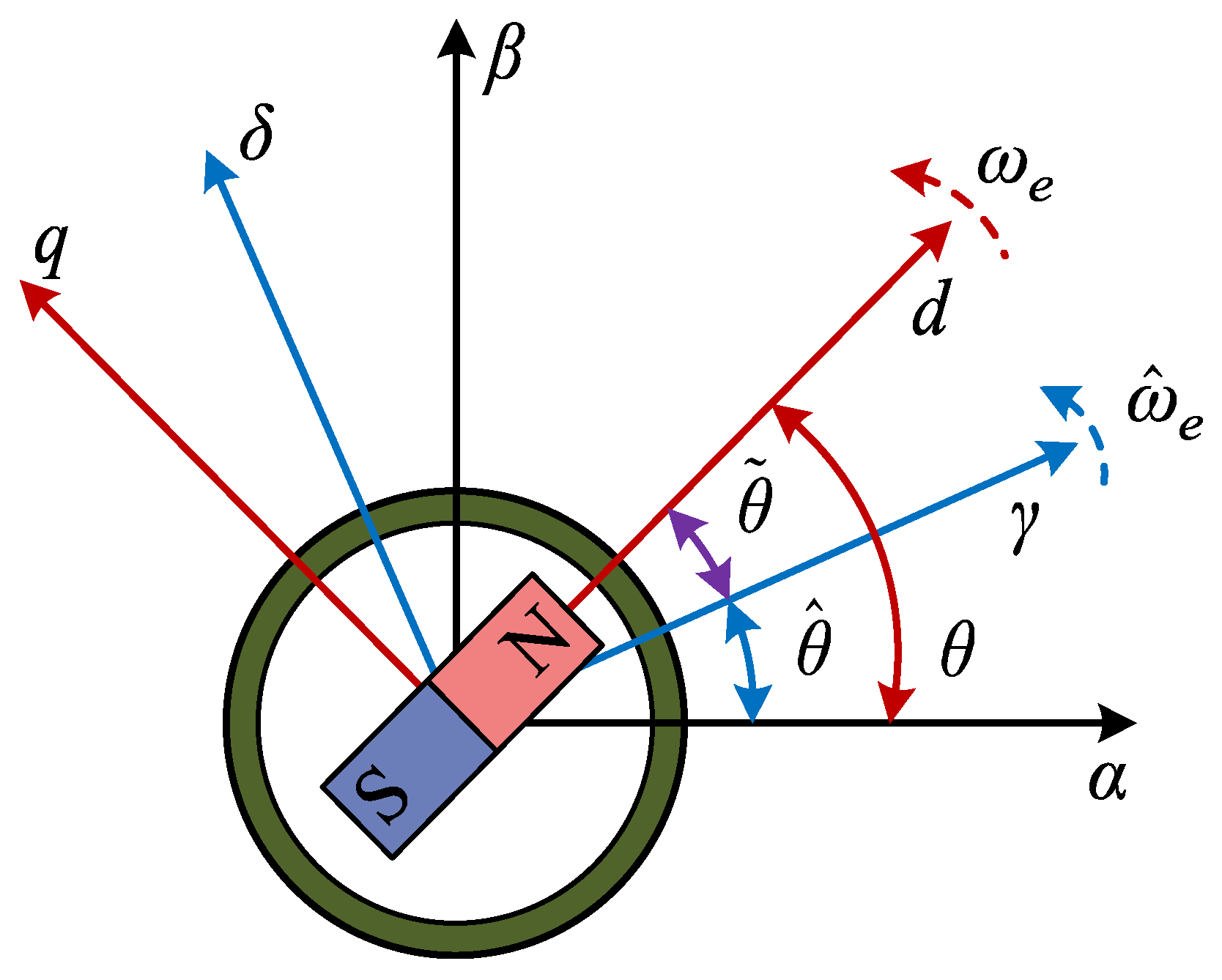
The characteristics of major model-based sensorless algorithms are presented in Table 2. In addition, these observers can be constructed either in the stationary frame (α-β) or in the estimated frame (γ-δ) [88,106,107]. The relationship of these frames is shown in Figure 14. In the α-β frame, the stator voltage, current and back EMF are orthogonal. The rotor position and speed are included in the phase and amplitude of the back EMF. The γ-δ frame is aligned with the estimated rotor position. The estimated back EMF reflects the position error between the estimated γ-δ frame and the actual d-q frame. Forcing the error to converge to zero is the key of estimation in the synchronous frame.

3.2. Position and Speed Extraction

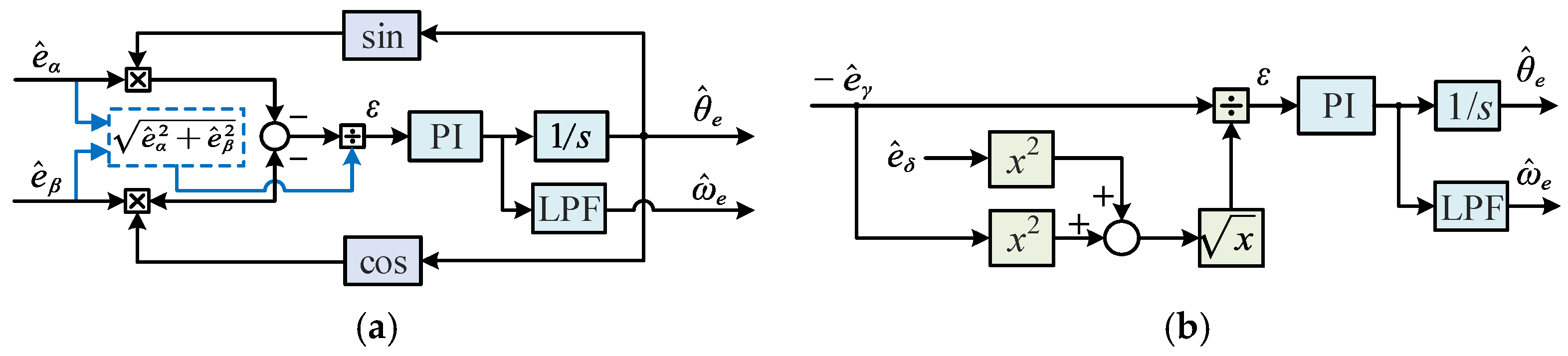
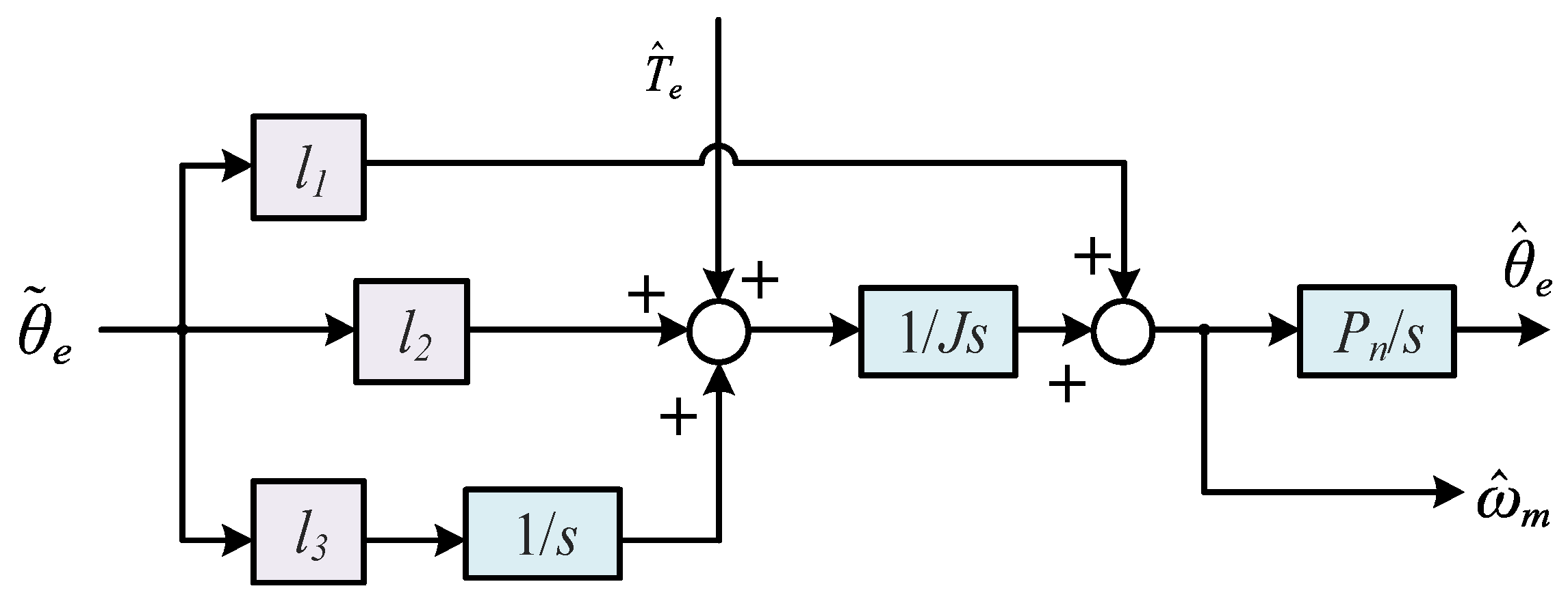
After obtaining the rotor flux or back EMF, the rotor position and speed need to be extracted to achieve sensorless control. As shown in Figure 15, the rotor position can be directly obtained using the arctangent function, and the speed is the derivative of the position. This method is simple and fast, but the calculation process is sensitive to disturbances, and differential operations are easily affected by noise [46,108]. Currently, the phase-locked loop is the mainstream method for position and speed extraction. Figure 16 shows the block diagrams of PLL in both the α-β frame and the γ-δ frame. A PI regulator is commonly used to eliminate the angular error for position tracking. The low-pass characteristic of the PLL can filter out unwanted harmonics and improve estimation accuracy but at the expense of degraded dynamic performance [47,48,49,50,51]. Compared with the PLL, the Luenberger observer has faster dynamic response, but the moment of inertia is necessary [22,109]. The block diagram of the Luenburger position observer is presented in Figure 17.

3.3. Model-Based Observers Under Non-Ideal Conditions

3.3.1. Parameter Mismatch

Due to the model dependency of the aforementioned methods, motor parameters have a significant impact on the sensorless control. Usually, the nominal parameters of the motor are used in the flux or back-EMF observer, which are provided by the motor manufacturer. However, actual motor parameters vary with operating conditions [110,111]. For instance, winding resistance is sensitive to temperature and the PM flux decays with temperature rise [112,113]. The key parameters of the motor are also influenced by variations in load conditions [114]. These variations lead to observer model mismatch, and there is a deviation between the estimated state and the actual state. This will further lead to errors in position and speed estimation and degrades the performance of sensorless control [115,116].
The model sensitivity of the model-based method has been discussed in [117], which highlights the effects of the q-axis inductance and resistance. This part will further analyze the impact of parameter mismatch on the accuracy of back-EMF-based methods. The parameter deviation is defined as follows.
R ˜ s = R s R ^ s L ˜ d = L d L ^ d L ˜ q = L q L ^ q
where variables with “~” represent the deviation values and variables with “^” represent the nominal values.
In the γ-δ frame, the position error caused by parameter mismatch can be derived as
θ ˜ sin θ ˜ = L ˜ d d i ^ γ d t + R ˜ s i ^ γ     ω ^ L ˜ q i ^ δ + D γ V d e a d ω ψ f
where DγVdead is the influence of dead-time effect for the PWM inverter.
It can be found that the d-axis inductance influences the error in the transient state. When the motor is operating in the steady state, the current differential term can be ignored. Errors in the q-axis inductance and stator resistance result in a position estimation error, which appears as a DC offset. The impact of dead time presents as error fluctuations of six times the fundamental frequency and will increase during low-speed operation. For the SPMSM with id = 0 control, the error Equation (28) can be simplified as
θ ˜ sin θ ˜ = ω ^ L ˜ q i ^ δ + D γ V d e a d ω ψ f
According to (29), the mismatched resistance will not cause a position error under id = 0 control.
To address the parameter mismatch, parameter identification is a direct solution [118,119,120,121]. However, conventional parameter identification methods with position sensors are not suitable for the sensorless system, as position error θ ~ is an extra unknown state [122]. To address this issue, [123] utilizes the inherent PWM current ripple of the voltage source inverter for inductance identification. Reference [124] uses a first-order discrete-time model in the γ-δ frame to identify the inductance, which is independent of flux error, initial rotor position error, and inverter nonlinearity. In [125], a rotor position-offset injection method is proposed for parameter estimation of sensorless controlled PMSMs. The amplitude of the q-axis voltage fluctuation decreases with the increasing accuracy of parameters during the position-offset injection, and thus, stator inductance and resistance can be estimated by controlling the q-axis voltage fluctuation. Reference [126] proposes a noniterative method to simultaneously obtain the resistance and inductance of HSPMSM based on a multi-frequency disturbance injection. The voltage distortion caused by the dead-time effect (DTE) is modeled as an equivalent DTE resistance. In [127], virtual signal injection methods are proposed for full-parameter estimation. When a positive and a negative virtual signal is injected into a flux observer, the position error is only related to the ratio of the γ-δ axis voltage fluctuation. Therefore, the parameters can be independent of position error and inverter nonlinearity at different speeds and loads.

3.3.2. Low Carrier Ratio

As the power and speed increase, the PMSM drive system often operates at a low carrier ratio (fratio = fPWM/fe), with the lowest carrier ratio generally below 10 [128]. The performance degradation, discretization error and instability of sensorless control have gradually attracted attention [129,130,131].
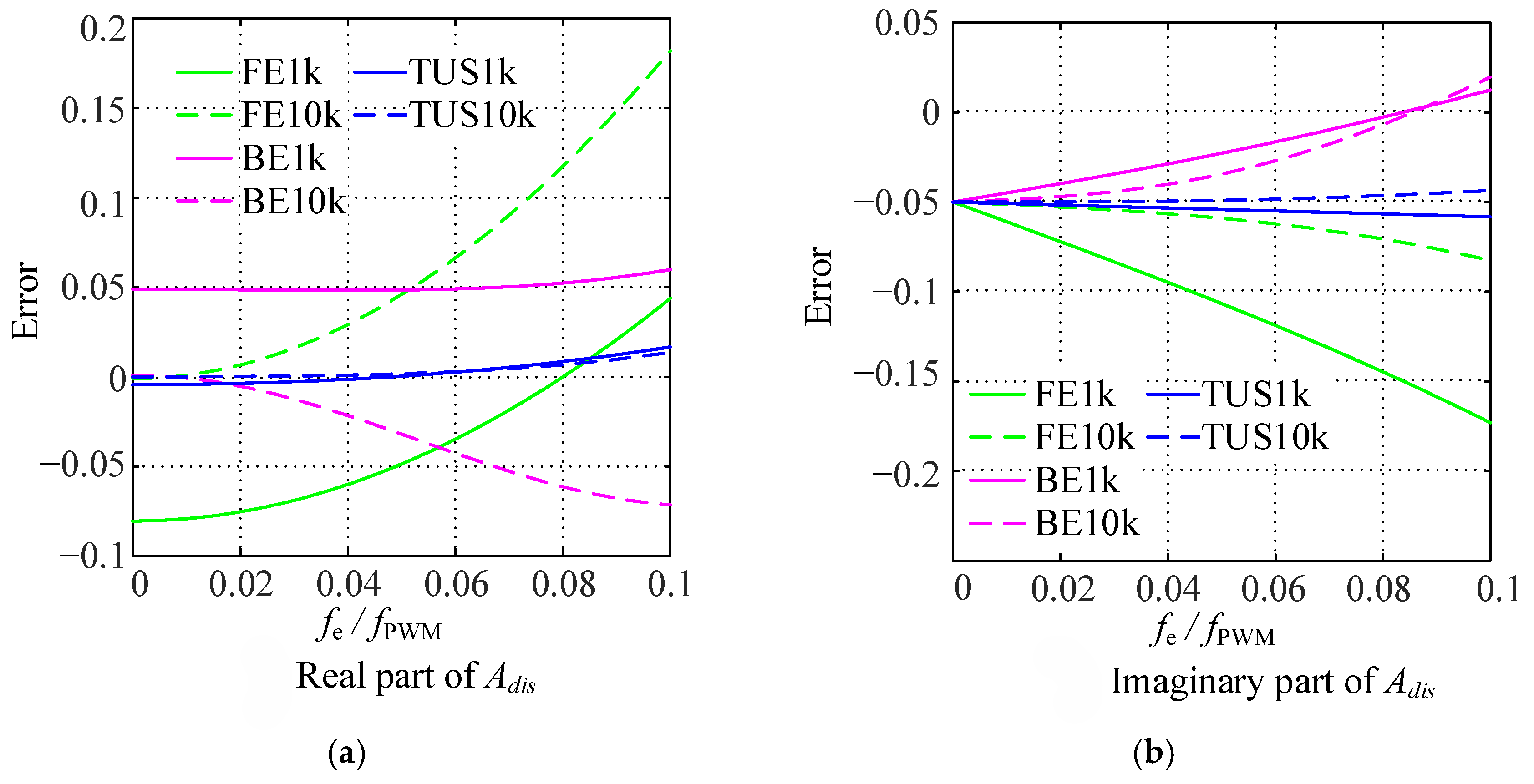
The existing sensorless control algorithms are generally designed in the continuous-time domain, and then some approximate discretization methods are used to implement the observer in the digital controller, such as the forward Euler method, backward Euler method, Tustin method, etc. Essentially, these methods are approximations of the state-space equations discretized using the zero-order hold (ZOH). The discrete models obtained by different discretization methods (in the d-q frame, neglecting back EMF) can be uniformly expressed as
i d q k + 1 = A d i s i d q k + B d i s u d q k
The discretization errors between different discretization methods and the ZOH method are shown in Figure 18. The backward Euler method has a smaller error than the forward Euler method, but the errors at low carrier ratio are both relatively large. Compared with using approximate methods, the observer designed by precise discretization can achieve a lower carrier ratio.
In [132], the discretization errors of forward Euler, backward Euler, Tustin, and pre-corrected Tustin methods are compared, and it points out that the discretization accuracy of the Tustin method is higher at different sampling frequencies. Reference [77] uses a precisely discretized SMO to achieve sensorless control with a carrier ratio of 20 at a switching frequency of 2 kHz. Reference [133] proposes a discrete-time adaptive synchronous-frequency observer, achieving a carrier ratio of 5. Reference [134] derives the discretization model of the IPMSM and proposes a discrete full-order state observer. The zero-pole matching method is adopted to configure the discrete-domain poles, achieving stable control with a minimum carrier ratio of 2.5.

3.3.3. Back-EMF Harmonics

Another critical issue is the harmonics in the estimation results of the model-based method, which are introduced by periodic disturbances in the motor drive system [135]. The various types of disturbance sources and back-EMF harmonic orders are summarized in [107]. In the process of motor design and manufacturing, achieving an ideal sinusoidal PM flux is challenging. The harmonics of back EMF are mainly low-order harmonics, such as the 3rd, 5th and 7th harmonics. For traditional three-phase star-winding PMSMs, the 3rd harmonics are zero-sequence components and do not cause current harmonics due to a no flow path. Therefore, the non-ideal flux will cause the −5th and +7th harmonics, which is the ±6th harmonics in the d-q frame. The effect of dead time is similar. The distortion of voltage caused by dead time will generate 6th harmonics in the estimation of rotor position and speed, which is significant at low speeds [136,137]. The three-phase asymmetries will cause negative-sequence components and cause 2nd harmonics in estimated back EMFs [15,138].
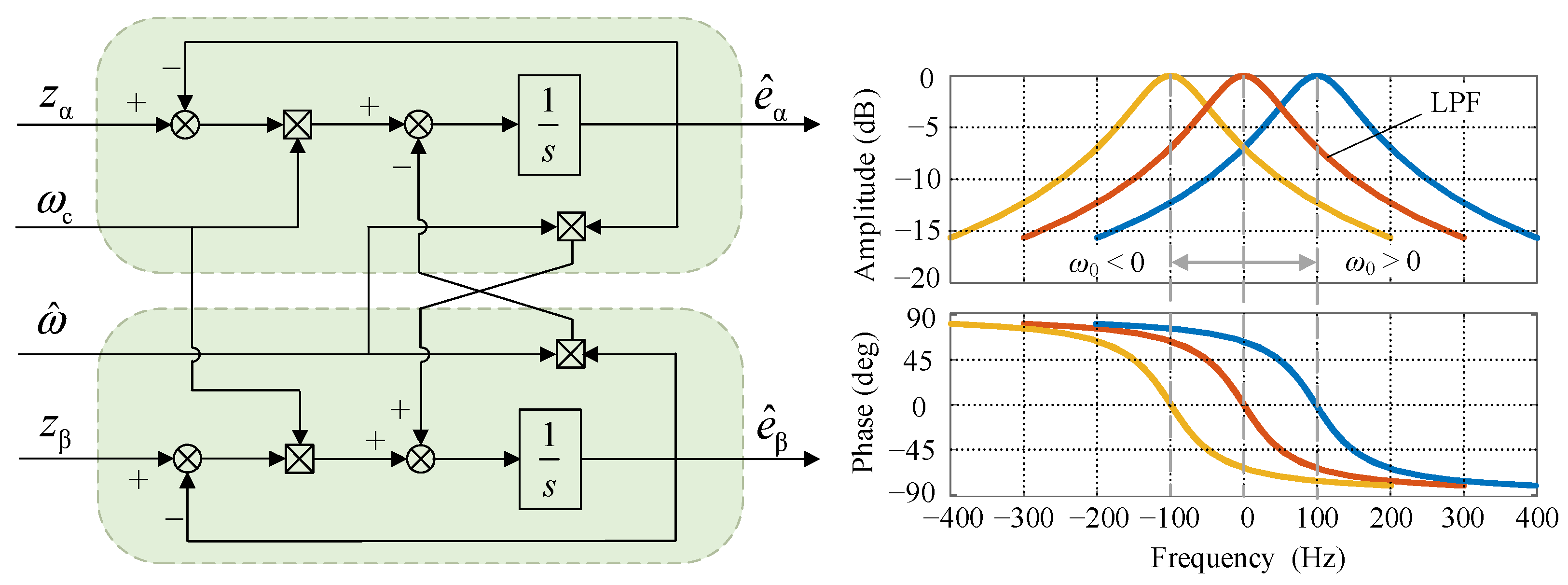
In order to suppress the harmonics in the estimated back EMF, additional filter networks are studied [139]. Frequency-adaptive band-pass filters are widely used for the characteristic of frequency selection. In [72], a frequency-adaptive complex-coefficient filter (FACCF) is proposed to suppress the low-order harmonics of the estimated back EMF and the chattering of the SMO. The structure and Bode diagram of FACCF are shown in Figure 19. In addition, adaptive notch filters (ANFs) are adopted to eliminate specific-order harmonics [140]. Compared with band-pass filters, the band-stop characteristic offers it a stronger ability to suppress the 5th and 7th harmonics. In addition to employing filters, constructing an observer with a harmonic suppression capability is also a feasible solution. In [141], a quasi-proportional-resonant controller (QPRC) is used to replace the signum function of SMO, which introduces a band-pass characteristic for the proposed observer. Reference [142] proposes a master–slave-structure observer for multi-harmonics suppression. The proposed observer does not affect the fundamental frequency signal but has a harmonic suppression effect similar to ANFs.

3.3.4. Zero/Low-Speed Operation

As aforementioned, the model-based sensorless methods possibly fail during the zero/low-speed operation. The model observability analysis of PMSMs provides a theoretical explanation for the poor performance at zero/low speed [143,144,145,146]. The convergence of model-based sensorless methods relies on a sufficient condition that the state variables must be locally weakly observable at a given operating point. For the highly nonlinear motor system, this property can be verified through Lie derivative analysis. The observability criterion matrix for determining local weak observability is defined as
O = L f 0 h 1 i α L f 0 h 1 i β L f 0 h 1 θ e L f 0 h 1 ω e L f 0 h 2 i α L f 0 h 2 i β L f 0 h 2 θ e L f 0 h 2 ω e L f 3 h 2 i α L f 3 h 2 i β L f 3 h 2 θ e L f 3 h 2 ω e ( 8 × 4 )
As demonstrated in [143], the determinant of the observability matrix can be derived as
δ L d i q d t δ L + ψ f δ L d i d d t + ω δ L 2 i d 2 + i q 2 + ψ f ψ f + 2 δ L i d 0
where δL = Ld − Lq.
For the IPMSMs, δL ≠ 0. When the motor runs at zero speed (or near to zero speed), the observability condition can be reduced to
i d + ψ f δ L C i q
where C is a constant. Equation (33) indicates that the state of IPMSMs in the zero or low-speed is observable when the d-q axis currents change but are not linearly synchronized. For the SPMSMs, δL = 0. Thus, a well-known sufficient observability condition can be obtained as
ω e 0
However, the derivation of (32) is based on the assumption that the rotor speed varies slowly. Considering rotor acceleration, the observability criteria in [147] can be expressed as
ψ f 2 L s 2 R s L s + f v J ω ˙ e 0
Thus, the state of an SPMSM is observable when ωe satisfies
ω e 0     ω ˙ e 0
According to the analysis above, the main challenges for model-based sensorless control in the zero/low-speed region can be summarized as follows: compensation for inverter nonlinearity, parameter robustness, start-up and speed reversal. When the dead-time compensation and motor parameters are accurate, the motor state is observable at low speeds. However, as the errors exist in reality, the state variables become unobservable under certain conditions, ultimately leading to system instability. Therefore, proactive identification of both inverter nonlinearity and motor parameters is necessary.
Typically, to achieve full-speed-range sensorless control, the I/F control or HFSI methods are usually adopted as the start-up strategy. However, this multi-strategy switching is complex and time-consuming. For situations with a fast start-up and frequent speed reversal, such switching is not desirable. Recently, research attention has been shifting toward sensorless methods capable of full-speed-range operation. For the SPMSMs at standstill, the sufficient condition for observability is the existence of rotor acceleration. It is necessary to apply torque to the rotor to break it from the stationary state. Subsequently, the observer promptly acquires reliable position information, which is then used for speed and torque control. Thus, fast and reliable rotor position acquisition following a brief uncontrollable interval is the critical requirement for start-up. Currently, several cases of the single sensorless control method achieving full-speed-range operation have been documented. Reference [147] proposes a full-order adaptive flux observer featuring virtual hybrid voltage injection, which achieves stable operation at zero speed at a rated load. The nonlinear flux observer in [61] and the voltage model observer in [148] perform well during start-up and speed reversal. However, load-driving capability, reliable start-up and stable rotation reversal are still common challenges for these methods.

3.4. High–Low Speed Switching Strategy

When combined strategies of high-speed and low-speed methods are adopted, a smooth and robust transition between different algorithms is the key to avoiding speed or torque ripple and maintaining system stability. Since the switching between the virtual frequency method and the model-based method has been analyzed in the previous section, this subsection mainly introduces the switching strategies between saliency-based and model-based methods.
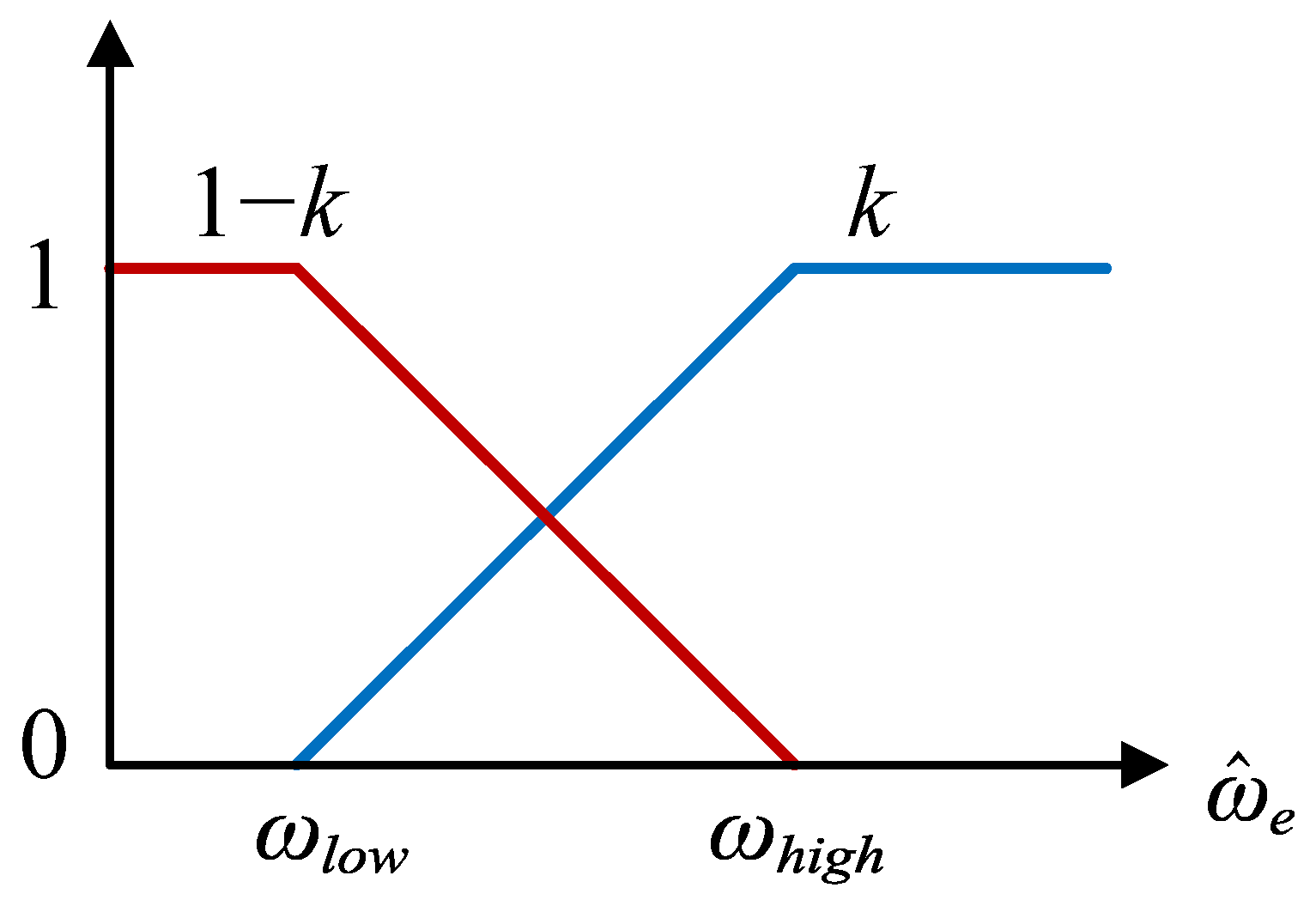
Currently, the dominant approach is weighted switching, which can be further categorized into position/speed weighting [149,150] and error signal weighting [151,152]. The former operates dual position observers simultaneously and fuses their estimated results via weighting coefficients for output. Since two position observers are employed, the low-speed and high-speed responses can be adjusted independently, but the computational burden increases accordingly. As for the error signal weighting, the normalized position errors of both the HF model and fundamental model are combined by a weighting function and used as the input to a PLL. This approach is easier to implement and requires fewer parameters to tune. The speed-based weighting function is shown as Figure 20. The estimated result of the weighted average is
θ ^ r = ( 1 k ) × θ ^ h + k × θ ^ f
where θ ^ r is the final result, and θ ^ h and θ ^ f are results of saliency-based and model-based methods. k is the weighting coefficient, which can be calculated as
k = 0 ( ω ^ e ω l o w ) / ( ω h i g h ω l o w ) 1 ω ^ e < ω l o w ω l o w < ω ^ e < ω h i g h ω ^ e > ω h i g h
where ωlow and ωhigh are the low-speed and high-speed boundaries of the transition region, respectively. Besides linearly varying weighting coefficients, [149] adopts fuzzy weighting coefficients, which also achieves a smooth transition between algorithms.
Furthermore, an alternative strategy is to build a unified hybrid model combining the high-frequency and fundamental models. In [153], a quadratic BEMF model was applied, which integrates the position extraction of the injection method and the model-based method into a unified framework, thereby achieving seamless switching. Research following the same approach can be found in [154,155].

4. Discussion

This article reviews the state-of-the-art sensorless control techniques for PMSMs. Research on sensorless control has progressively shifted toward performance optimization to enhance its engineering applicability. This section focuses on the analysis of sensorless algorithms for specific application scenarios, serving as a reference for engineering practice. Furthermore, key challenges and emerging trends are discussed as well.

4.1. Application-Oriented Analysis and Implementation Insights

Different sensorless control techniques possess distinct strengths and limitations, and their suitability is critically determined by the particular needs and constraints of the application field. Key systematic evaluation indicators for these methods include minimum operating speed, dynamic response, parameter robustness, computational complexity, cost, and dependence on motor saliency, as partially summarized in Table 1 and Table 2. The following analysis will be conducted in combination with specific application scenarios.
Table 3 presents some typical application scenarios and their core requirements. For the numerous fans and pumps in industrial systems, their load is proportional to the square of the rotational speed. During the start-up, I/F control is sufficient. As the speed increases, a transition is made to model-based high-speed methods.
For home appliances, which have stringent requirements for cost and failure rate, reliable and easy-to-implement algorithms are the preferred choice. Since a high-frequency injection generates noise and the FPE method has high hardware requirements, I/F control can be adopted for start-up in the low-speed stage and then switched to high-speed methods. Among high-speed methods, the sliding-mode observer is widely used due to its simple implementation and strong robustness. Algorithms with high computational burden, such as EKF, are not applicable in these low-cost systems.
In recent years, electric vehicles have developed rapidly. For safety considerations, sensorless control can be employed as a backup in the event of position-sensor failure. Current main drive PM motors are mostly IPMSMs to fully utilize reluctance torque and flux-weakening speed expansion capability. The saliency-based HFSI methods have significant application value, but it is necessary to reduce injection noise to improve driving comfort. Since motor parameters vary significantly under different operating conditions, the adopted sensorless algorithm should be incorporated with online parameter identification to enhance parameter robustness.
Currently, there is no universally optimal algorithm as the selection of a technique is the result of tradeoffs under specific application constraints. Future research should focus on scenario-oriented algorithm design and the establishment of standardized testing benchmarks to accelerate technology transfer.

4.2. Challenge and Future Research Trends

4.2.1. Dynamic Response Enhancement in Full Speed Range

Achieving dynamic performance comparable to that of sensored PMSM control has always been a primary goal for sensorless techniques. The inherent tradeoff between dynamic response and estimation accuracy is a common challenge faced by both low-speed and high-speed sensorless algorithms. Consequently, enhancing dynamic response is a crucial prerequisite for realizing high-performance sensorless control and ultimately replacing mechanical position sensors.

4.2.2. Sensorless Drives Under Low Carrier Ratio

Sensorless control under low carrier ratios is another critical challenge. High-power motor systems with low switching frequencies and ultra-high-speed PMSM drives for special applications are current research focuses. For both operating conditions, sensorless techniques under low carrier ratios still face unresolved issues that require further investigation.

4.2.3. Improvement in Parameter Robustness for Sensorless Control

Parameter sensitivity remains a fundamental constraint for sensorless control algorithms, directly impacting stability and accuracy. In addition to enhancing the inherent robustness of algorithms, integrating real-time motor parameter identification is also a viable solution. Looking forward, the focus should shift toward adaptive, self-learning systems combined with intelligent algorithms to achieve universal sensorless control.

4.2.4. Zero/Low-Speed Performance Enhancement of Model-Based Algorithms

Performance degradation in the zero/low-speed region remains a persistent weakness for model-based sensorless algorithms. However, a unified full-speed-range method is the optimal engineering solution, rather than the currently adopted hybrid strategy. Overcoming difficulties of the mode-based method in start-up and speed reversal, as well as further expanding the low-speed operating range, are crucial for the practical application of sensorless algorithms.

4.2.5. AI and Data-Driven Sensorless Control

The aforementioned challenges (e.g., dynamic response, parameter robustness, low-speed performance) are fundamentally rooted in the strong dependence on accurate physical models and a priori knowledge. Recently, artificial intelligence (AI) and data-driven approaches have offered new solutions to these inherent constraints. The intrinsic advantage of such methods lies in their ability to directly learn the complex dynamic characteristics and nonlinear mapping relationships of motors from operational data, thereby reducing reliance on precise models.
Deep learning and reinforcement learning have been utilized for the online identification of key motor parameters and load disturbances [156,157]. Compared with traditional identification methods, they exhibit superior robustness to noise and model inaccuracies. AI techniques have also been incorporated into observer structures to improve the performance of position estimation [158,159]. Benefiting from the potential to learn complex nonlinear dynamics, the AI-based observers may achieve superior dynamic estimation performances across a wide speed range, particularly in the low-speed region. Moreover, using neural networks to model unknown or non-ideal factors proves to be a feasible and effective approach [160,161].
However, several obstacles must be overcome to facilitate the proliferation of AI in sensorless control, including the acquisition of sufficient and effective training data, the deployment of complex AI models on resource-constrained control chips, and concerns regarding reliability and safety.

5. Conclusions

For cost-sensitive and high-reliability applications, PMSM sensorless control is irreplaceable as it eliminates the need for traditional position sensors. This article provides a comprehensive review of existing sensorless control techniques and their latest developments. For the low-speed region, virtual frequency methods, high-frequency injection methods, and fundamental PWM excitation methods are introduced. For the medium-to-high-speed region, flux and back-EMF-based methods are reviewed, while also analyzing their performance degradation under non-ideal conditions. Finally, application-oriented analysis, implementation insights, as well as the challenges and future development trends of sensorless control are discussed. Currently, a performance gap still exists between sensorless control and sensored control. In the future, sensorless control with enhanced robustness and dynamic performance is expected to completely replace position sensors in a wider range of applications.

Author Contributions

Conceptualization, Q.A. and M.Z.; methodology, Q.A.; investigation, M.Z., S.Z. and H.W.; writing—original draft preparation, M.Z.; writing—review and editing, Q.A., Y.L., S.Z. and X.Z. All authors have read and agreed to the published version of the manuscript.

Funding

This research received no external funding.

Data Availability Statement

No new data were created or analyzed in this study. Data sharing is not applicable to this article.

Conflicts of Interest

The authors declare no conflicts of interest.

References

  1. An, Q.; Lu, Y.; Zhao, M. Review of Key Technologies of the High-Speed Permanent Magnet Motor Drive. Energies 2024, 17, 5252. [Google Scholar] [CrossRef] [Scilit]
  2. Yan, H.; Wang, W.; Xu, Y.; Zou, J. Position Sensorless Control for PMSM Drives With Single Current Sensor. IEEE Trans. Ind. Electron. 2023, 70, 178–188. [Google Scholar] [CrossRef] [Scilit]
  3. Cao, F.; An, Q.; Zhang, J.; Zhao, M.; Li, S. Variable Weighting Coefficient of EMF-Based Enhanced Sliding Mode Observer for Sensorless PMSM Drives. Energies 2022, 15, 6001. [Google Scholar] [CrossRef] [Scilit]
  4. Tang, Q.; Chen, D.; He, X. Integration of Improved Flux Linkage Observer and I–f Starting Method for Wide-Speed-Range Sensorless SPMSM Drives. IEEE Trans. Power Electron. 2020, 35, 8374–8383. [Google Scholar] [CrossRef] [Scilit]
  5. Xing, J.; Qin, Z.; Lin, C.; Jiang, X. Research on Startup Process for Sensorless Control of PMSMs Based on I-F Method Combined With an Adaptive Compensator. IEEE Access 2020, 8, 70812–70821. [Google Scholar] [CrossRef] [Scilit]
  6. Niu, L.; Zhai, J.; Liu, X.; Wang, Y.; Gupta, A.K. A smooth and fast transition method for PMSM SMO based sensorless control. In Proceedings of the 2016 IEEE 2nd Annual Southern Power Electronics Conference (SPEC), Auckland, New Zealand, 5–8 December 2016; pp. 1–6. [Google Scholar]
  7. Zhang, Y.; Xu, W.; Wang, J. A Rapid Sensorless Startup Method with Instantaneous Control Mode Switching for High-Speed Vane-Motor Based on Hybrid Speed-Position-Current Tracking Controller. IEEE Trans. Power Electron. 2024, 39, 6125–6135. [Google Scholar] [CrossRef] [Scilit]
  8. Ye, M.; Cao, Y.; Chen, W.; Shi, T.; Xia, C. Full-Speed-Range Sensorless Control of High-Speed Permanent Magnet Synchronous Motor Based on the Prediction Methodology. IEEE Trans. Power Electron. 2025, 40, 3405–3418. [Google Scholar] [CrossRef] [Scilit]
  9. Bi, G.; Zhang, G.; Wang, Q.; Ding, D.; Li, B.; Wang, G.; Xu, D. High-Frequency Injection Angle Self-Adjustment Based Online Position Error Suppression Method for Sensorless PMSM Drives. IEEE Trans. Power Electron. 2023, 38, 1412–1417. [Google Scholar] [CrossRef] [Scilit]
  10. Wang, S.; Li, Z.; Wu, D.; Zhao, J. Sensorless Control of SPMSM Based on High-Frequency Positive- and Negative-Sequence Current Dual-Demodulation. IEEE Trans. Ind. Electron. 2023, 70, 4631–4639. [Google Scholar] [CrossRef] [Scilit]
  11. Kim, S.-I.; Im, J.-H.; Song, E.-Y.; Kim, R.-Y. A New Rotor Position Estimation Method of IPMSM Using All-Pass Filter on High-Frequency Rotating Voltage Signal Injection. IEEE Trans. Ind. Electron. 2016, 63, 6499–6509. [Google Scholar] [CrossRef] [Scilit]
  12. Naderian, M.; Markadeh, G.A.; Karimi-Ghartemani, M.; Mojiri, M. Improved Sensorless Control Strategy for IPMSM Using an ePLL Approach with High-Frequency Injection. IEEE Trans. Ind. Electron. 2024, 71, 2231–2241. [Google Scholar] [CrossRef] [Scilit]
  13. Chen, P.; Ma, R.; Bai, H.; Chen, Z.; Song, S. Rotating High Frequency Voltage Injection Strategy Considering Time Delay for PMSM Based on Dual Heterodyne Method. IEEE Trans. Energy Convers. 2025, 40, 901–910. [Google Scholar] [CrossRef] [Scilit]
  14. Wang, G.; Xiao, D.; Zhang, G.; Li, C.; Zhang, X.; Xu, D.G. Sensorless Control Scheme of IPMSMs Using HF Orthogonal Square-Wave Voltage Injection into a Stationary Reference Frame. IEEE Trans. Power Electron. 2019, 34, 2573–2584. [Google Scholar] [CrossRef] [Scilit]
  15. Chen, Y.; Wu, X.; Zhu, Z.Q.; Liu, C. Improved Pulsating Signal Injection Sensorless Control of Dual Three-Phase IPMSMs With Arbitrary Inductance Asymmetries in One Set Three-Phase Windings. IEEE Trans. Ind. Appl. 2024, 60, 6277–6290. [Google Scholar] [CrossRef] [Scilit]
  16. Lee, Y.-R.; Sul, S.-K. Switching Frequency Signal-Injection Sensorless Control in Dual Three-Phase PMSM Robust to Nonideal Characteristics of Inverter System. IEEE Trans. Power Electron. 2024, 39, 8540–8552. [Google Scholar] [CrossRef] [Scilit]
  17. Yu, K.; Wang, Z. Position Sensorless Control of IPMSM Using Adjustable Frequency Setting Square-Wave Voltage Injection. IEEE Trans. Power Electron. 2022, 37, 12973–12979. [Google Scholar] [CrossRef] [Scilit]
  18. Yoon, Y.-D.; Sul, S.-K.; Morimoto, S.; Ide, K. High-Bandwidth Sensorless Algorithm for AC Machines Based on Square-Wave-Type Voltage Injection. IEEE Trans. Ind. Appl. 2011, 47, 1361–1370. [Google Scholar] [CrossRef] [Scilit]
  19. Benevieri, A.; Formentini, A.; Marchesoni, M.; Passalacqua, M.; Vaccaro, L. Sensorless Control with Switching Frequency Square Wave Voltage Injection for SPMSM With Low Rotor Magnetic Anisotropy. IEEE Trans. Power Electron. 2023, 38, 10060–10072. [Google Scholar] [CrossRef] [Scilit]
  20. Jiang, S.; Ren, L.; Wang, X.; Xie, M.; Bian, C.; Wang, D. Permanent Magnet Synchronous Motor Control System with Filterless High Frequency Square Wave Injection. In Proceedings of the 2024 IEEE 7th International Electrical and Energy Conference (CIEEC), Harbin, China, 10–12 May 2024; pp. 58–63. [Google Scholar] [CrossRef] [Scilit]
  21. Zhang, Z.; Zhou, S.; Li, H.; Qiu, J. A Novel Demodulation for Pulsating Carrier Voltage Injection-Based Encoderless Control. IEEE Trans. Power Electron. 2025, 40, 118–123. [Google Scholar] [CrossRef] [Scilit]
  22. Yang, S.-C.; Lorenz, R.D. Surface Permanent-Magnet Machine Self-Sensing at Zero and Low Speeds Using Improved Observer for Position, Velocity, and Disturbance Torque Estimation. IEEE Trans. Ind. Appl. 2012, 48, 151–160. [Google Scholar] [CrossRef] [Scilit]
  23. Qian, W.; Zhang, X.; Jin, F.; Bai, H.; Lu, D.; Cheng, B. Using High-Control-Bandwidth FPGA and SiC Inverters to Enhance High-Frequency Injection Sensorless Control in Interior Permanent Magnet Synchronous Machine. IEEE Access 2018, 6, 42454–42466. [Google Scholar] [CrossRef] [Scilit]
  24. Kroneisl, M.; Smidl, V.; Peroutka, Z.; Janda, M. Predictive Control of IM Drive Acoustic Noise. IEEE Trans. Ind. Electron. 2020, 67, 5666–5676. [Google Scholar] [CrossRef] [Scilit]
  25. Wang, G.; Yang, L.; Yuan, B.; Wang, B.; Zhang, G.; Xu, D. Pseudo-Random High-Frequency Square-Wave Voltage Injection Based Sensorless Control of IPMSM Drives for Audible Noise Reduction. IEEE Trans. Ind. Electron. 2016, 63, 7423–7433. [Google Scholar] [CrossRef] [Scilit]
  26. Wang, G.; Yang, L.; Zhang, G.; Zhang, X.; Xu, D. Comparative Investigation of Pseudorandom High-Frequency Signal Injection Schemes for Sensorless IPMSM Drives. IEEE Trans. Power Electron. 2017, 32, 2123–2132. [Google Scholar] [CrossRef] [Scilit]
  27. Zhang, G.; Xiang, R.; Wang, G.; Li, C.; Bi, G.; Zhao, N.; Xu, D. Hybrid Pseudorandom Signal Injection for Position Sensorless SynRM Drives with Acoustic Noise Reduction. IEEE Trans. Transp. Electrif. 2022, 8, 1313–1325. [Google Scholar] [CrossRef] [Scilit]
  28. Zhang, G.; Li, S.; Li, B.; Wang, Q.; Wang, G.; Xu, D. Acoustic Noise Reduction Using Half-Period- Switching Pseudorandom Sinusoidal Injection with External Tangent Demodulation for Sensorless PMSM Drives. IEEE Trans. Transp. Electrif. 2025, 11, 5312–5323. [Google Scholar] [CrossRef] [Scilit]
  29. Hwang, C.-E.; Lee, Y.; Sul, S.-K. Analysis on Position Estimation Error in Position-Sensorless Operation of IPMSM Using Pulsating Square Wave Signal Injection. IEEE Trans. Ind. Appl. 2019, 55, 458–470. [Google Scholar] [CrossRef] [Scilit]
  30. Shuang, B.; Zhu, Z.-Q. A Novel Method for Estimating the High Frequency Incremental DQ-Axis and Cross-Coupling Inductances in Interior Permanent Magnet Synchronous Machines. IEEE Trans. Ind. Appl. 2021, 57, 4913–4923. [Google Scholar] [CrossRef] [Scilit]
  31. Chen, Z.; Gao, J.; Wang, F.; Ma, Z.; Zhang, Z.; Kennel, R. Sensorless Control for SPMSM With Concentrated Windings Using Multisignal Injection Method. IEEE Trans. Ind. Electron. 2014, 61, 6624–6634. [Google Scholar] [CrossRef] [Scilit]
  32. Li, X.; Yan, Y.; Xu, Y.; Chen, W.; Shi, T.; Xia, C. Low-Speed Rotating Restart and Speed Recording for Free-Running Sensorless IPMSM Based on Ultrahigh Frequency Sinusoidal Wave Injection. IEEE Trans. Power Electron. 2022, 37, 15245–15259. [Google Scholar] [CrossRef] [Scilit]
  33. Aihara, T.; Toba, A.; Yanase, T.; Mashimo, A.; Endo, K. Sensorless torque control of salient-pole synchronous motor at zero-speed operation. IEEE Trans. Power Electron. 1999, 14, 202–208. [Google Scholar] [CrossRef] [Scilit]
  34. Kim, H.; Huh, K.-K.; Lorenz, R.; Jahns, T. A novel method for initial rotor position estimation for IPM synchronous machine drives. IEEE Trans. Ind. Appl. 2004, 40, 1369–1378. [Google Scholar] [CrossRef] [Scilit]
  35. Wang, G.; Zhang, G.; Yang, R.; Xu, D. Robust Low-Cost Control Scheme of Direct-Drive Gearless Traction Machine for Elevators Without a Weight Transducer. IEEE Trans. Ind. Appl. 2012, 48, 996–1005. [Google Scholar] [CrossRef] [Scilit]
  36. Xu, P.; Zhu, Z.Q. Initial Rotor Position Estimation Using Zero-Sequence Carrier Voltage for Permanent-Magnet Synchronous Machines. IEEE Trans. Ind. Electron. 2017, 64, 149–158. [Google Scholar] [CrossRef] [Scilit]
  37. Jeong, Y.-S.; Lorenz, R.; Jahns, T.; Sul, S.-K. Initial rotor position estimation of an interior permanent-magnet synchronous machine using carrier-frequency injection methods. IEEE Trans. Ind. Appl. 2005, 41, 38–45. [Google Scholar] [CrossRef] [Scilit]
  38. Schroedl, M. Detection of the rotor position of a permanent magnet synchronous machine at standstill. In Proceedings of the International Conference on Electrical Machines (ICEM), Pisa, Italy, 12–14 September 1988; pp. 195–197. [Google Scholar]
  39. Robeischl, E.; Schroedl, M. Optimized INFORM measurement sequence for sensorless PM synchronous motor drives with respect to minimum current distortion. IEEE Trans. Ind. Appl. 2004, 40, 591–598. [Google Scholar] [CrossRef] [Scilit]
  40. Luo, X.; Tang, Q.; Shen, A.; Shen, H.; Xu, J. A Combining FPE and Additional Test Vectors Hybrid Strategy for IPMSM Sensorless Control. IEEE Trans. Power Electron. 2018, 33, 6104–6113. [Google Scholar] [CrossRef] [Scilit]
  41. Staines, C.; Caruana, C.; Asher, G.; Sumner, M. Sensorless control of induction Machines at zero and low frequency using zero sequence currents. IEEE Trans. Ind. Electron. 2006, 53, 195–206. [Google Scholar] [CrossRef] [Scilit]
  42. Zhao, C.; Tanaskovic, M.; Percacci, F.; Mariethoz, S.; Gnos, P. Sensorless position estimation for slotless surface mounted permanent magnet synchronous motors in full speed range. In Proceedings of the 2017 IEEE International Symposium on Sensorless Control for Electrical Drives (SLED), Catania, Italy, 18–19 September 2017; pp. 193–198. [Google Scholar] [CrossRef] [Scilit]
  43. Hind, D.; Li, C.; Sumner, M.; Gerada, C. Realising robust low speed sensorless PMSM control using current derivatives obtained from standard current sensors. In Proceedings of the 2017 IEEE International Electric Machines and Drives Conference (IEMDC), Miami, FL, USA, 21–24 May 2017; pp. 1–6. [Google Scholar] [CrossRef] [Scilit]
  44. Wang, G.; Kuang, J.; Zhao, N.; Zhang, G.; Xu, D. Rotor Position Estimation of PMSM in Low-Speed Region and Standstill Using Zero-Voltage Vector Injection. IEEE Trans. Power Electron. 2018, 33, 7948–7958. [Google Scholar] [CrossRef] [Scilit]
  45. Xie, G.; Lu, K.; Dwivedi, S.K.; Riber, R.J.; Wu, W. Permanent Magnet Flux Online Estimation Based on Zero-Voltage Vector Injection Method. IEEE Trans. Power Electron. 2015, 30, 6506–6509. [Google Scholar] [CrossRef] [Scilit]
  46. An, Q.; Zhao, M.; Ma, T.; Wu, Y. Deadbeat Predictive Algorithm-Based Back EMF Observer for Sensorless Control of PMSM Drives. IEEE Trans. Ind. Electron. 2025, 72, 8985–8994. [Google Scholar] [CrossRef] [Scilit]
  47. Bierhoff, M.H. A General PLL-Type Algorithm for Speed Sensorless Control of Electrical Drives. IEEE Trans. Ind. Electron. 2017, 64, 9253–9260. [Google Scholar] [CrossRef] [Scilit]
  48. Yin, Z.; Zhang, Y.; Cao, X.; Yuan, D.; Liu, J. Estimated Position Error Suppression Using Novel PLL for IPMSM Sensorless Drives Based on Full-Order SMO. IEEE Trans. Power Electron. 2022, 37, 4463–4474. [Google Scholar] [CrossRef] [Scilit]
  49. Chen, Z.; Dawara, A.A.; Zhang, X.; Zhang, H.; Liu, C.; Luo, G. Adaptive Sliding Mode Observer-Based Sensorless Control for SPMSM Employing a Dual-PLL. IEEE Trans. Transp. Electrif. 2022, 8, 1267–1277. [Google Scholar] [CrossRef] [Scilit]
  50. Wu, X.; Li, C.; Zhang, Y.; Chen, S.; Ma, Z.; Han, Y.; Zhang, X.; Tan, G. Sensorless Control of IPMSM Equipped with LC Sinusoidal Filter Based on Full-Order Sliding Mode Observer and Feedforward QPLL. IEEE Trans. Power Electron. 2024, 39, 8072–8085. [Google Scholar] [CrossRef] [Scilit]
  51. Wu, C.; Wu, C.; Zheng, L.; Dai, Z. A General Phase-Locked Loop to Enhance Sensorless Control of PMSM Based on Back Electromotive Force. IEEE Trans. Ind. Electron. 2025, 72, 2285–2296. [Google Scholar] [CrossRef] [Scilit]
  52. Ye, S.; Yao, X. A Modified Flux Sliding-Mode Observer for the Sensorless Control of PMSMs With Online Stator Resistance and Inductance Estimation. IEEE Trans. Power Electron. 2020, 35, 8652–8662. [Google Scholar] [CrossRef] [Scilit]
  53. Zhao, J.; Wang, G.; Zhang, G.; Hao, Y.; Zhao, N.; Hu, Z.; Zhu, L.; Xu, D. Extended Flux Projection Vector Observer Based Position Error Compensation Strategy for Sensorless Direct Torque Controlled PMSM Drives. IEEE Trans. Power Electron. 2025, 40, 8416–8429. [Google Scholar] [CrossRef] [Scilit]
  54. Wang, A.; Chen, D.; Tao, L.; Han, F.; Hu, Z.; Wang, H.; Qiao, H.; Wang, J. Two-Stage Active-Flux Observer for Position Sensorless Control of PMSM Drives with Output Filter. In Proceedings of the 2023 26th International Conference on Electrical Machines and Systems (ICEMS), Zhuhai, China, 5–8 November 2023; pp. 5032–5037. [Google Scholar] [CrossRef] [Scilit]
  55. Jin, D.; Liu, L.; Liang, D. A Flux Observer Based on a Dual-Layer Adaptive Algorithm for SPMSMs Position Sensorless Drive. IEEE J. Emerg. Sel. Top. Power Electron. 2025, 13, 2358–2371. [Google Scholar] [CrossRef] [Scilit]
  56. Ge, Y.; Song, W.; Yang, Y.; Wheeler, P. A Polar-Coordinate-Multisignal-Flux-Observer-Based PMSM Non-PLL Sensorless Control. IEEE Trans. Power Electron. 2023, 38, 10579–10583. [Google Scholar] [CrossRef] [Scilit]
  57. Boldea, I.; Paicu, M.C.; Andreescu, G.-D. Active Flux Concept for Motion-Sensorless Unified AC Drives. IEEE Trans. Power Electron. 2008, 23, 2612–2618. [Google Scholar] [CrossRef] [Scilit]
  58. Tajima, H.; Hori, Y. Speed sensorless field-orientation control of the induction machine. IEEE Trans. Ind. Appl. 1993, 29, 175–180. [Google Scholar] [CrossRef] [Scilit]
  59. Wipasuramonton, P.; Zhu, Z.Q.; Howe, D. Sensorless vector control of non-salient BLAC machines based on a modified rotor flux-linkage observer. In Proceedings of the 2009 International Conference on Power Electronics and Drive Systems (PEDS 2009), Taipei, Taiwan, 2–5 November 2009; pp. 1056–1061. [Google Scholar] [CrossRef] [Scilit]
  60. Kashif, M.; Murshid, S.; Singh, B. Solar PV Array Fed Self-Sensing Control of PMSM Drive With Robust Adaptive Hybrid SOGI Based Flux Observer for Water Pumping. IEEE Trans. Ind. Electron. 2021, 68, 6962–6972. [Google Scholar] [CrossRef] [Scilit]
  61. Lee, J.; Hong, J.; Nam, K.; Ortega, R.; Praly, L.; Astolfi, A. Sensorless Control of Surface-Mount Permanent-Magnet Synchronous Motors Based on a Nonlinear Observer. IEEE Trans. Power Electron. 2010, 25, 290–297. [Google Scholar] [CrossRef] [Scilit]
  62. Liu, J.; Zhang, Y. Performance Improvement of Nonlinear Flux Observer for Sensorless Control of PMSM. IEEE Trans. Ind. Electron. 2023, 70, 12014–12023. [Google Scholar] [CrossRef] [Scilit]
  63. Liu, S.; Liu, L.; Lin, Q.; Jin, D.; Liang, D. A High Order Nonlinear Adaptive Observer for PMSM Speed-Flux Transformation Model: A PMSM Sensorless Control Scheme. IEEE Trans. Power Electron. 2025, 40, 10889–10898. [Google Scholar] [CrossRef] [Scilit]
  64. Filho, C.J.V.; Xiao, D.; Vieira, R.P.; Emadi, A. Observers for High-Speed Sensorless PMSM Drives: Design Methods, Tuning Challenges and Future Trends. IEEE Access 2021, 9, 56397–56415. [Google Scholar] [CrossRef] [Scilit]
  65. Chen, Z.; Tomita, M.; Doki, S.; Okuma, S. An extended electromotive force model for sensorless control of interior permanent-magnet synchronous motors. IEEE Trans. Ind. Electron. 2003, 50, 288–295. [Google Scholar] [CrossRef] [Scilit]
  66. Wang, G.; Valla, M.I.; Solsona, J.A. Position Sensorless Permanent Magnet Synchronous Machine Drives—A Review. IEEE Trans. Ind. Electron. 2020, 67, 5830–5842. [Google Scholar] [CrossRef] [Scilit]
  67. Zuo, Y.; Lai, C.; Iyer, K.L.V. A Review of Sliding Mode Observer Based Sensorless Control Methods for PMSM Drive. IEEE Trans. Power Electron. 2023, 38, 11352–11367. [Google Scholar] [CrossRef] [Scilit]
  68. Cheng, Z.; Li, L.; Liu, X.; Bai, X.; Liu, J. Sensorless Control Based on Discrete Fractional-Order Terminal Sliding Mode Observer for High-Speed PMSM With LCL Filter. IEEE Trans. Power Electron. 2025, 40, 1654–1668. [Google Scholar] [CrossRef] [Scilit]
  69. Wang, Y.; Xu, Y.; Zou, J. Sliding-Mode Sensorless Control of PMSM With Inverter Nonlinearity Compensation. IEEE Trans. Power Electron. 2019, 34, 10206–10220. [Google Scholar] [CrossRef] [Scilit]
  70. Liang, J.; Wu, J.; Wang, Y.; Zhong, Z.; Bai, X. Sensorless Control for a Permanent Magnet Synchronous Motor Based on a Sliding Mode Observer. Eng 2024, 5, 1737–1751. [Google Scholar] [CrossRef] [Scilit]
  71. Ma, Z.; Zhang, X. FPGA Implementation of Sensorless Sliding Mode Observer with a Novel Rotation Direction Detection for PMSM Drives. IEEE Access 2018, 6, 55528–55536. [Google Scholar] [CrossRef] [Scilit]
  72. An, Q.; Zhang, J.; An, Q.; Liu, X.; Shamekov, A.; Bi, K. Frequency-Adaptive Complex-Coefficient Filter-Based Enhanced Sliding Mode Observer for Sensorless Control of Permanent Magnet Synchronous Motor Drives. IEEE Trans. Ind. Appl. 2020, 56, 335–343. [Google Scholar] [CrossRef] [Scilit]
  73. Chi, S.; Zhang, Z.; Xu, L. Sliding-Mode Sensorless Control of Direct-Drive PM Synchronous Motors for Washing Machine Applications. IEEE Trans. Ind. Appl. 2009, 45, 582–590. [Google Scholar] [CrossRef] [Scilit]
  74. Kim, H.; Son, J.; Lee, J. A High-Speed Sliding-Mode Observer for the Sensorless Speed Control of a PMSM. IEEE Trans. Ind. Electron. 2011, 58, 4069–4077. [Google Scholar] [CrossRef] [Scilit]
  75. Qiao, Z.; Shi, T.; Wang, Y.; Yan, Y.; Xia, C.; He, X. New Sliding-Mode Observer for Position Sensorless Control of Permanent-Magnet Synchronous Motor. IEEE Trans. Ind. Electron. 2013, 60, 710–719. [Google Scholar] [CrossRef] [Scilit]
  76. Sheng, L.; Li, W.; Wang, Y.; Fan, M.; Yang, X. Sensorless Control of a Shearer Short-Range Cutting Interior Permanent Magnet Synchronous Motor Based on a New Sliding Mode Observer. IEEE Access 2017, 5, 18439–18450. [Google Scholar] [CrossRef] [Scilit]
  77. Ding, L.; Li, Y.W.; Zargari, N.R. Discrete-Time SMO Sensorless Control of Current Source Converter-Fed PMSM Drives with Low Switching Frequency. IEEE Trans. Ind. Electron. 2021, 68, 2120–2129. [Google Scholar] [CrossRef] [Scilit]
  78. Srikanth, V.; Dutt, A.A. A comparative study on the effect of switching functions in SMO for PMSM drives. In Proceedings of the 2012 IEEE International Conference on Power Electronics, Drives and Energy Systems (PEDES), Bengaluru, India, 16–19 December 2012; pp. 1–6. [Google Scholar] [CrossRef] [Scilit]
  79. Slotine, J.J.; Sastry, S.S. Tracking control of non-linear systems using sliding surfaces with application to robot manipulators. In Proceedings of the 1983 American Control Conference, San Francisco, CA, USA, 22–24 June 1983; pp. 132–135. [Google Scholar] [CrossRef] [Scilit]
  80. Zhong, Y.; Lin, H.; Wang, J.; Yang, H. Improved Adaptive Sliding-Mode Observer Based Position Sensorless Control for Variable Flux Memory Machines. IEEE Trans. Power Electron. 2023, 38, 6395–6406. [Google Scholar] [CrossRef] [Scilit]
  81. Xu, W.; Qu, S.; Zhao, J.; Zhang, H.; Du, X. An Improved Full-Order Sliding-Mode Observer for Rotor Position and Speed Estimation of SPMSM. IEEE Access 2021, 9, 15099–15109. [Google Scholar] [CrossRef] [Scilit]
  82. Liang, D.; Li, J.; Qu, R.; Kong, W. Adaptive Second-Order Sliding-Mode Observer for PMSM Sensorless Control Considering VSI Nonlinearity. IEEE Trans. Power Electron. 2018, 33, 8994–9004. [Google Scholar] [CrossRef] [Scilit]
  83. Chen, L.; Jin, Z.; Shao, K.; Wang, H.; Wang, G.; Iu, H.H.-C.; Fernando, T. Sensorless Fixed-Time Sliding Mode Control of PMSM Based on Barrier Function Adaptive Super-Twisting Observer. IEEE Trans. Power Electron. 2024, 39, 3037–3051. [Google Scholar] [CrossRef] [Scilit]
  84. Zhao, L.; Huang, J.; Liu, H.; Li, B.; Kong, W. Second-Order Sliding-Mode Observer with Online Parameter Identification for Sensorless Induction Motor Drives. IEEE Trans. Ind. Electron. 2014, 61, 5280–5289. [Google Scholar] [CrossRef] [Scilit]
  85. Bolognani, S.; Calligaro, S.; Petrella, R. Design Issues and Estimation Errors Analysis of Back-EMF-Based Position and Speed Observer for SPM Synchronous Motors. IEEE J. Emerg. Sel. Top. Power Electron. 2014, 2, 159–170. [Google Scholar] [CrossRef] [Scilit]
  86. Filho, C.J.V.; Vieira, R.P. Adaptive Full-Order Observer Analysis and Design for Sensorless Interior Permanent Magnet Synchronous Motors Drives. IEEE Trans. Ind. Electron. 2021, 68, 6527–6536. [Google Scholar] [CrossRef] [Scilit]

  87. Hinkkanen, M.; Tuovinen, T.; Harnefors, L.; Luomi, J. A Combined Position and Stator-Resistance Observer for Salient PMSM Drives: Design and Stability Analysis. IEEE Trans. Power Electron. 2012, 27, 601–609. [Google Scholar] [CrossRef] [Scilit]
  88. Tuovinen, T.; Hinkkanen, M.; Harnefors, L.; Luomi, J. Comparison of a Reduced-Order Observer and a Full-Order Observer for Sensorless Synchronous Motor Drives. IEEE Trans. Ind. Appl. 2012, 48, 1959–1967. [Google Scholar] [CrossRef] [Scilit]
  89. Yu, Y.; Shao, Y.; Chai, F.; Cui, M. Static-Errorless Position Estimation for Sensorless PMSM Drives with Enhanced Robustness Against the Full-Frequency Domain Disturbance. IEEE Trans. Power Electron. 2022, 37, 5884–5897. [Google Scholar] [CrossRef] [Scilit]
  90. Yin, Z.; Gao, F.; Zhang, Y.; Du, C.; Li, G.; Sun, X. A review of nonlinear Kalman filter appling to sensorless control for AC motor drives. CES Trans. Electr. Mach. Syst. 2019, 3, 351–362. [Google Scholar] [CrossRef] [Scilit]
  91. Zerdali, E. Adaptive Extended Kalman Filter for Speed-Sensorless Control of Induction Motors. IEEE Trans. Energy Convers. 2019, 34, 789–800. [Google Scholar] [CrossRef] [Scilit]
  92. Yin, Z.; Li, G.; Zhang, Y.; Liu, J.; Sun, X.; Zhong, Y. A Speed and Flux Observer of Induction Motor Based on Extended Kalman Filter and Markov Chain. IEEE Trans. Power Electron. 2017, 32, 7096–7117. [Google Scholar] [CrossRef] [Scilit]
  93. Bolognani, S.; Tubiana, L.; Zigliotto, M. Extended Kalman filter tuning in sensorless PMSM drives. IEEE Trans. Ind. Appl. 2003, 39, 1741–1747. [Google Scholar] [CrossRef] [Scilit]
  94. Cao, R.; Jiang, N.; Lu, M. Sensorless Control of Linear Flux-Switching Permanent Magnet Motor Based on Extended Kalman Filter. IEEE Trans. Ind. Electron. 2020, 67, 5971–5979. [Google Scholar] [CrossRef] [Scilit]
  95. Smidl, V.; Peroutka, Z. Advantages of Square-Root Extended Kalman Filter for Sensorless Control of AC Drives. IEEE Trans. Ind. Electron. 2012, 59, 4189–4196. [Google Scholar] [CrossRef] [Scilit]
  96. Li, Y.; Li, J.; Qi, J.; Chen, L. Robust Cubature Kalman Filter for Dynamic State Estimation of Synchronous Machines Under Unknown Measurement Noise Statistics. IEEE Access 2019, 7, 29139–29148. [Google Scholar] [CrossRef] [Scilit]
  97. Niedermayr, P.; Alberti, L.; Bolognani, S.; Abl, R. Implementation and Experimental Validation of Ultrahigh-Speed PMSM Sensorless Control by Means of Extended Kalman Filter. IEEE J. Emerg. Sel. Top. Power Electron. 2022, 10, 3337–3344. [Google Scholar] [CrossRef] [Scilit]
  98. Kim, Y.-H.; Kook, Y.-S. High performance IPMSM drives without rotational position sensors using reduced-order EKF. IEEE Trans. Energy Convers. 1999, 14, 868–873. [Google Scholar] [CrossRef] [Scilit]
  99. Yang, H.; Yang, R.; Hu, W.; Huang, Z. FPGA-Based Sensorless Speed Control of PMSM Using Enhanced Performance Controller Based on the Reduced-Order EKF. IEEE J. Emerg. Sel. Top. Power Electron. 2021, 9, 289–301. [Google Scholar] [CrossRef] [Scilit]
  100. Piippo, A.; Hinkkanen, M.; Luomi, J. Adaptation of Motor Parameters in Sensorless PMSM Drives. IEEE Trans. Ind. Appl. 2009, 45, 203–212. [Google Scholar] [CrossRef] [Scilit]
  101. Wang, H.; Ge, X.; Liu, Y.-C. Second-Order Sliding-Mode MRAS Observer-Based Sensorless Vector Control of Linear Induction Motor Drives for Medium-Low Speed Maglev Applications. IEEE Trans. Ind. Electron. 2018, 65, 9938–9952. [Google Scholar] [CrossRef] [Scilit]
  102. Tang, Y.; Xu, W.; Liu, Y.; Dong, D. Dynamic Performance Enhancement Method Based on Improved Model Reference Adaptive System for SPMSM Sensorless Drives. IEEE Access 2021, 9, 135012–135023. [Google Scholar] [CrossRef] [Scilit]
  103. Sun, X.; Zhang, Y.; Tian, X.; Cao, J.; Zhu, J. Speed Sensorless Control for IPMSMs Using a Modified MRAS With Gray Wolf Optimization Algorithm. IEEE Trans. Transp. Electrif. 2022, 8, 1326–1337. [Google Scholar] [CrossRef] [Scilit]
  104. Yang, Y.; Sun, X.; Cai, F. Speed Sensorless Control of IPMSM With Model Predictive Current Control Plus Finite Position Set MRAS Observer. IEEE Trans. Transp. Electrif. 2025, 11, 4755–4764. [Google Scholar] [CrossRef] [Scilit]
  105. Bi, G.; Chen, Y.; Wang, K.; Cao, S.; Yang, T. Sensorless Control Design and Stability Analysis of High-Speed Dual Three-Phase Permanent Motor Drive for Future Aircraft Applications. IEEE Trans. Power Electron. 2025, 40, 16169–16183. [Google Scholar] [CrossRef] [Scilit]
  106. Kshirsagar, P.; Burgos, R.P.; Jang, J.; Lidozzi, A.; Wang, F.; Boroyevich, D.; Sul, S.-K. Implementation and Sensorless Vector-Control Design and Tuning Strategy for SMPM Machines in Fan-Type Applications. IEEE Trans. Ind. Appl. 2012, 48, 2402–2413. [Google Scholar] [CrossRef] [Scilit]
  107. Du, P.; Wang, B.; Xu, D. A BEMF Harmonic-Extended State γδ -Axes Observer for PMSM Sensorless Control Reducing Structural Redundancy. IEEE Trans. Ind. Electron. 2025, 72, 4623–4638. [Google Scholar] [CrossRef] [Scilit]
  108. Liang, D.; Li, J.; Qu, R. Sensorless Control of Permanent Magnet Synchronous Machine Based on Second-Order Sliding-Mode Observer With Online Resistance Estimation. IEEE Trans. Ind. Appl. 2017, 53, 3672–3682. [Google Scholar] [CrossRef] [Scilit]
  109. Yoo, A.; Sul, S.-K.; Lee, D.-C.; Jun, C.-S. Novel Speed and Rotor Position Estimation Strategy Using a Dual Observer for Low-Resolution Position Sensors. IEEE Trans. Power Electron. 2009, 24, 2897–2906. [Google Scholar] [CrossRef] [Scilit]
  110. Rafaq, M.S.; Jung, J.-W. A Comprehensive Review of State-of-the-Art Parameter Estimation Techniques for Permanent Magnet Synchronous Motors in Wide Speed Range. IEEE Trans. Ind. Inform. 2020, 16, 4747–4758. [Google Scholar] [CrossRef] [Scilit]

  111. Yu, Y.; Huang, X.; Li, Z.; Wu, M.; Shi, T.; Cao, Y.; Yang, G.; Niu, F. Full Parameter Estimation for Permanent Magnet Synchronous Motors. IEEE Trans. Ind. Electron. 2022, 69, 4376–4386. [Google Scholar] [CrossRef] [Scilit]
  112. Yang, C.; Song, B.; Jatskevich, J.; Zhang, H.; Lee, C.H.T. Normal-Operation-Undisturbed Magnet Flux Linkage Monitoring in PMSM Drives via a Mechanical-Model-Based Dual Time-Scale Approach. IEEE Trans. Ind. Inform. 2024, 20, 6266–6279. [Google Scholar] [CrossRef] [Scilit]
  113. Wang, P.; Zhu, Z.Q.; Liang, D. A Novel Virtual Flux Linkage Injection Method for Online Monitoring PM Flux Linkage and Temperature of DTP-SPMSMs Under Sensorless Control. IEEE Trans. Ind. Electron. 2025, 72, 12529–12543. [Google Scholar] [CrossRef] [Scilit]
  114. Yang, C.; Liu, W.; Song, B.; Xie, X.; Niu, S.; Chau, K.T. Signal-Injection-Based Efficient Direct-Determination of Controller Gains and Nonlinear Friction Compensation Values in SPMSM Drives. IEEE Trans. Power Electron. 2026, 41, 1627–1633. [Google Scholar] [CrossRef] [Scilit]
  115. Kivanc, O.C.; Ozturk, S.B. Sensorless PMSM Drive Based on Stator Feedforward Voltage Estimation Improved with MRAS Multiparameter Estimation. IEEE/ASME Trans. Mechatron. 2018, 23, 1326–1337. [Google Scholar] [CrossRef] [Scilit]
  116. Wu, C.; Zhao, Y.; Sun, M. Enhancing Low-Speed Sensorless Control of PMSM Using Phase Voltage Measurements and Online Multiple Parameter Identification. IEEE Trans. Power Electron. 2020, 35, 10700–10710. [Google Scholar] [CrossRef] [Scilit]
  117. Bolognani, S.; Ortombina, L.; Tinazzi, F.; Zigliotto, M. Model sensitivity of fundamental-frequency-based position estimators for sensorless pm and reluctance synchronous motor drives. IEEE Trans. Ind. Electron. 2018, 65, 77–85. [Google Scholar] [CrossRef] [Scilit]
  118. Zhu, Z.Q.; Liang, D.; Liu, K. Online Parameter Estimation for Permanent Magnet Synchronous Machines: An Overview. IEEE Access 2021, 9, 59059–59084. [Google Scholar] [CrossRef] [Scilit]
  119. Liu, Z.; Kong, W.; Liu, H.; Peng, K.; Wang, F.; Fan, X.; Qu, R. Online Multiparameter Estimation with Position Error Correction for Unified Synchronous Machine Sensorless Drives. IEEE Trans. Ind. Appl. 2025, 61, 345–358. [Google Scholar] [CrossRef] [Scilit]
  120. Yang, Q.; Mao, K.; Zheng, S.; Zhou, C.; Zhong, Q. Position Sensorless Drive with Online Parameters Estimation for Magnetic Suspension Centrifugal Compressor. IEEE Trans. Power Electron. 2023, 38, 9384–9394. [Google Scholar] [CrossRef] [Scilit]
  121. Yao, Y.; Huang, Y.; Peng, F.; Dong, J. Position Sensorless Drive and Online Parameter Estimation for Surface-Mounted PMSMs Based on Adaptive Full-State Feedback Control. IEEE Trans. Power Electron. 2020, 35, 7341–7355. [Google Scholar] [CrossRef] [Scilit]
  122. Liu, Z.; Shen, B.; Kong, W.; Fan, X.; Peng, K.; Qu, R. Analytical Approach for Position Observation Error Correction in IPMSM Sensorless Drives Using Online Multiparameter Estimation. IEEE Trans. Power Electron. 2024, 39, 9230–9243. [Google Scholar] [CrossRef] [Scilit]
  123. Zhang, J.; Peng, F.; Huang, Y.; Yao, Y.; Zhu, Z. Online Inductance Identification Using PWM Current Ripple for Position Sensorless Drive of High-Speed Surface-Mounted Permanent Magnet Synchronous Machines. IEEE Trans. Ind. Electron. 2022, 69, 12426–12436. [Google Scholar] [CrossRef] [Scilit]
  124. Hu, Y.; Liu, K.; Hua, W.; Hu, M. First-Order Model Based Inductance Identification with Least Square Method for High-Speed Sensorless Control of Permanent Magnet Synchronous Machines. IEEE Trans. Power Electron. 2023, 38, 8719–8729. [Google Scholar] [CrossRef] [Scilit]
  125. Zhu, Z.Q.; Wang, P.; Freire, N.M.A.; Azar, Z.; Wu, X. A Novel Rotor Position-Offset Injection-Based Online Parameter Estimation of Sensorless Controlled Surface-Mounted PMSMs. IEEE Trans. Energy Convers. 2024, 39, 1930–1946. [Google Scholar] [CrossRef] [Scilit]
  126. Hu, Y.; Hua, W.; Hu, M.; Wang, Y. Inductance–Resistance Online Identification for Sensorless High-Speed PMSM Considering Resistive Characteristic of Invertor Nonlinearity. IEEE Trans. Ind. Electron. 2024, 71, 2343–2355. [Google Scholar] [CrossRef] [Scilit]
  127. Wang, P.; Zhu, Z.Q.; Liang, D. Virtual Signal Injection-Based Online Full-Parameter Estimation of Surface-Mounted PMSMs Without Influence of Position Error and Inverter Nonlinearity. IEEE J. Emerg. Sel. Top. Power Electron. 2025, 13, 2341–2357. [Google Scholar] [CrossRef] [Scilit]
  128. Wang, M.; Buticchi, G.; Li, J.; Gu, C.; Gerada, D.; Degano, M.; Xu, L.; Li, Y.; Zhang, H.; Geradab, C. Decoupled Discrete Current Control for AC Drives at Low Sampling-to-Fundamental Frequency Ratios. IEEE J. Emerg. Sel. Top. Power Electron. 2023, 11, 1358–1369. [Google Scholar] [CrossRef] [Scilit]
  129. Yuan, X.; Chen, J.; Jiang, C.; Lee, C.H.T. Discrete-Time Current Regulator for AC Machine Drives. IEEE Trans. Power Electron. 2022, 37, 5847–5858. [Google Scholar] [CrossRef] [Scilit]
  130. Ding, L.; Li, Y.W.; Zargari, N.; Paes, R. Sensorless Control of CSC-fed PMSM Drives with Low Switching frequency for Electrical Submersible Pump Application. IEEE Trans. Ind. Appl. 2020, 56, 3799–3808. [Google Scholar] [CrossRef] [Scilit]
  131. Hu, Y.; Hua, W.; Hu, M.; Wang, Y.; Yu, W. Injection-Free Rotor Position Estimation Error Compensation for Simplified Salient High-Speed Permanent Magnet Synchronous Machine Sensorless Drive. IEEE J. Emerg. Sel. Top. Power Electron. 2025, 13, 1812–1819. [Google Scholar] [CrossRef] [Scilit]
  132. Wang, B.; Zhao, Y.; Yu, Y.; Wang, G.; Xu, D.; Dong, Z. Speed-Sensorless Induction Machine Control in the Field-Weakening Region Using Discrete Speed-Adaptive Full-Order Observer. IEEE Trans. Power Electron. 2016, 31, 5759–5773. [Google Scholar] [CrossRef] [Scilit]
  133. Yin, Z.; Cao, X.; Zhang, Y.; Liu, J. A Novel SPMSM Sensorless Drive Using Discrete-Time Synchronous-Frequency Adaptive Observer Under Low Frequency Ratio. IEEE Trans. Power Electron. 2022, 37, 11045–11057. [Google Scholar] [CrossRef] [Scilit]
  134. Zhang, G.; Wang, G.; Xu, D.; Yu, Y. Discrete-Time Low-Frequency-Ratio Synchronous-Frame Full-Order Observer for Position Sensorless IPMSM Drives. IEEE J. Emerg. Sel. Top. Power Electron. 2017, 5, 870–879. [Google Scholar] [CrossRef] [Scilit]
  135. Lin, S.; Wang, W.; Fu, J.; Cui, P.; Zheng, Z. A Harmonic Current Suppression Method Based on Two-Dimensional Identification of Virtual Harmonic Back Electromotive Force for PMSM Drives. IEEE Trans. Ind. Electron. 2025, 72, 12516–12528. [Google Scholar] [CrossRef] [Scilit]
  136. Tang, Z.; Akin, B. Suppression of Dead-Time Distortion Through Revised Repetitive Controller in PMSM Drives. IEEE Trans. Energy Convers. 2017, 32, 918–930. [Google Scholar] [CrossRef] [Scilit]
  137. Chatterjee, D.; Chakraborty, C.; Dalapati, S. An Overview on Dead-Time Distortion and Its Correction in PWM Inverters. IEEE Open J. Power Electron. 2025, 6, 1453–1490. [Google Scholar] [CrossRef] [Scilit]
  138. Liu, T.Y.; Zhu, Z.Q.; Wu, Z.Y.; Stone, D.A.; Foster, M.P. Improved Sensorless Control Method and Asymmetric Phase Resistances Determination for Permanent Magnet Synchronous Machines. IEEE Trans. Ind. Appl. 2022, 58, 3624–3636. [Google Scholar] [CrossRef] [Scilit]
  139. Zhang, G.; Wang, G.; Xu, D.; Ni, R.; Jia, C. Multiple-AVF Cross-Feedback-Network-Based Position Error Harmonic Fluctuation Elimination for Sensorless IPMSM Drives. IEEE Trans. Ind. Electron. 2016, 63, 821–831. [Google Scholar] [CrossRef] [Scilit]
  140. Ge, Y.; Yang, L.; Ma, X. A Harmonic Compensation Method for SPMSM Sensorless Control Based on the Orthogonal Master-Slave Adaptive Notch Filter. IEEE Trans. Power Electron. 2021, 36, 11701–11711. [Google Scholar] [CrossRef] [Scilit]
  141. An, Q.; Zhang, J.; An, Q.; Shamekov, A. Quasi-Proportional-Resonant Controller Based Adaptive Position Observer for Sensorless Control of PMSM Drives Under Low Carrier Ratio. IEEE Trans. Ind. Electron. 2020, 67, 2564–2573. [Google Scholar] [CrossRef] [Scilit]
  142. Wang, B.; Du, P.; Tian, M.; Xu, D. A Master-Slave-Structure Position Observer for Multiharmonics Suppression in Sensorless PMSM Drives. IEEE Trans. Ind. Electron. 2024, 71, 4528–4540. [Google Scholar] [CrossRef] [Scilit]
  143. Vaclavek, P.; Blaha, P.; Herman, I. AC Drive Observability Analysis. IEEE Trans. Ind. Electron. 2013, 60, 3047–3059. [Google Scholar] [CrossRef] [Scilit]
  144. Koteich, M.; Maloum, A.; Duc, G.; Sandou, G. Discussion on “AC Drive Observability Analysis”. IEEE Trans. Ind. Electron. 2015, 62, 7224–7225. [Google Scholar] [CrossRef] [Scilit]
  145. Horváth, K.; Kuczmann, M. Impact of Coordinate System Selection and Model Observability on Position Sensorless State Estimation of Nonsalient-Pole PMSM. In Proceedings of the 2024 IEEE 21st International Power Electronics and Motion Control Conference (PEMC), Pilsen, Czech Republic, 30 September–3 October 2024; pp. 1–6. [Google Scholar] [CrossRef] [Scilit]
  146. Zaltni, D.; Abdelkrim, M.N.; Ghanes, M.; Barbot, J.P. Observability analysis of PMSM. In Proceedings of the 2009 3rd International Conference on Signals, Circuits and Systems (SCS 2009), Medenine, Tunisia, 6–8 November 2009; pp. 1–6. [Google Scholar] [CrossRef] [Scilit]
  147. Wang, K.; Wang, Q.; Zhang, G.; Han, J.; Ding, L.; Wang, S.; Wang, G.; Xu, D. Virtual Hybrid Voltage Injection-Based Sensorless Control of Surface PMSM Drives for Zero-Speed Operation. IEEE Trans. Transp. Electrif. 2025, 12, 8–20. [Google Scholar] [CrossRef] [Scilit]
  148. Jansson, M.; Harnefors, L.; Wallmark, O.; Leksell, M. Synchronization at startup and stable rotation reversal of sensorless nonsalient PMSM drives. IEEE Trans. Ind. Electron. 2006, 53, 379–387. [Google Scholar] [CrossRef] [Scilit]
  149. Wen, D.; Wang, W.; Zhang, Y. Sensorless Control of Permanent Magnet Synchronous Motor in Full Speed Range. Chin. J. Electr. Eng. 2022, 8, 97–107. [Google Scholar] [CrossRef] [Scilit]
  150. Wang, G.; Yang, R.; Xu, D. DSP-Based Control of Sensorless IPMSM Drives for Wide-Speed-Range Operation. IEEE Trans. Ind. Electron. 2013, 60, 720–727. [Google Scholar] [CrossRef] [Scilit]
  151. Wu, C.; Chen, Z.; Chen, Q. Hybrid-Modulation-Based Full-Speed Sensorless Control for Permanent Magnet Synchronous Motors. IEEE Trans. Power Electron. 2022, 37, 5908–5917. [Google Scholar] [CrossRef] [Scilit]
  152. Yang, S.-C.; Hsu, Y.-L. Full Speed Region Sensorless Drive of Permanent-Magnet Machine Combining Saliency-Based and Back-EMF-Based Drive. IEEE Trans. Ind. Electron. 2017, 64, 1092–1101. [Google Scholar] [CrossRef] [Scilit]
  153. Xiao, D.; Nalakath, S.; Filho, S.R.; Fang, G.; Dong, A.; Sun, Y.; Wiseman, J.; Emadi, A. Universal Full-Speed Sensorless Control Scheme for Interior Permanent Magnet Synchronous Motors. IEEE Trans. Power Electron. 2021, 36, 4723–4737. [Google Scholar] [CrossRef] [Scilit]
  154. Zhang, Y.; Yin, Z.; Gao, F.; Liu, J. IPMSM Unified Full-Speed Domain Sensorless Control Based on Generalized Integral Resonance Extended State Observer with Adaptive Bandwidth. IEEE Trans. Power Electron. 2025. early access. [Google Scholar] [CrossRef] [Scilit]
  155. Wang, H.; Yu, K.; Zhao, C.; Zuo, Y.; Zhu, J.; Lee, C.H.T. Seamless Sensorless Control for IPMSM Operating in Full Speed Range. IEEE Trans. Power Electron. 2026, 41, 4492–4497. [Google Scholar] [CrossRef] [Scilit]
  156. Bui, M.X.; Dutta, R.; Rahman, F. Application of Deep Learning in Parameter Estimation of Permanent Magnet Synchronous Machines. IEEE Access 2024, 12, 40710–40721. [Google Scholar] [CrossRef] [Scilit]
  157. Bui, M.; Nguyen, H.; Nutkani, I.; Fernando, W.; Dutta, R.; Rahman, M. Reinforcement Learning-Based Online Estimation of the Inductances of the Permanent Magnet Synchronous Machines. IEEE Trans. Instrum. Meas. 2025, 74, 3003212. [Google Scholar] [CrossRef] [Scilit]
  158. Zhao, Y.; Lim, C.S.; Xue, F.; Long, C.; Tan, A.H.P. Lightweight LSTM and GRU Design for Data-Driven Rotor Position Error Estimation in IPMSM Drives. IEEE Open J. Ind. Electron. Soc. 2025, 6, 851–867. [Google Scholar] [CrossRef] [Scilit]
  159. Shim, J.; Park, B.R.; Kim, M.; Ha, J.-I. Data-Driven Position Estimation and Sensorless Control of PMSM Drive in Low-Speed Region. IEEE Trans. Ind. Appl. 2026, 62, 1103–1116. [Google Scholar] [CrossRef] [Scilit]
  160. Tan, L.N.; Cong, T.P.; Cong, D.P. Neural Network Observers and Sensorless Robust Optimal Control for Partially Unknown PMSM With Disturbances and Saturating Voltages. IEEE Trans. Power Electron. 2021, 36, 12045–12056. [Google Scholar] [CrossRef] [Scilit]
  161. Liu, Z.; Kong, W.; Fan, X.; Li, Z.; Peng, K.; Qu, R. Hybrid Thermal Modeling With LPTN-Informed Neural Network for Multinode Temperature Estimation in PMSM. IEEE Trans. Power Electron. 2024, 39, 10897–10909. [Google Scholar] [CrossRef] [Scilit]
Figure 1. Classification of sensorless control methods for permanent magnet synchronous motors.
Energies 19 01112 g001
Figure 2. Block diagrams of two virtual frequency methods. (a) V/F control. (b) I/F control.
Energies 19 01112 g002
Figure 3. (a) Rotating signal injection; (b) pulsating signal injection.
Energies 19 01112 g003
Figure 4. Waveform schematic diagram of random high-frequency square-wave voltage udh and current response idh. T1 and T2 are different signal periods, respectively.
Energies 19 01112 g004
Figure 5. (a) Rotor position when polarity is uncertain; (b) nonlinear magnetization characteristic of stator core.
Energies 19 01112 g005
Figure 6. General composition of model-based sensorless control algorithms.
Energies 19 01112 g006
Figure 7. Phasor diagram of flux linkage of an SPMSM.
Energies 19 01112 g007
Figure 8. Block diagram of flux-based sensorless control.
Energies 19 01112 g008
Figure 9. General block diagram of an observer.
Energies 19 01112 g009
Figure 10. (a) Conventional SMO. (b) Super-twisting SMO.
Energies 19 01112 g010
Figure 11. Block diagram of Luenburger observer.
Energies 19 01112 g011
Figure 12. Block diagram of extended Kalman filter.
Energies 19 01112 g012
Figure 13. Block diagram of MRAS method.
Energies 19 01112 g013
Figure 14. Relationships among α-β, d-q, and γ-δ reference frames.
Energies 19 01112 g014
Figure 15. Position and speed extraction through arctangent and derivative method.
Energies 19 01112 g015
Figure 16. Position and speed extraction through PLL. (a) α-β frame. (b) γ-δ frame.
Energies 19 01112 g016
Figure 17. Position and speed extraction through Luenberger observer.
Energies 19 01112 g017
Figure 18. Discretization errors between different discretization methods and the ZOH method. (a) Discretization error of the real part. (b) Discretization error of the imaginary part.
Energies 19 01112 g018
Figure 19. Structure and Bode diagram of FACCF; ω0 is the central frequency. Reproduced with permission from Quntao An, Transactions on Industry Applications; published by IEEE, 2020 [72].
Energies 19 01112 g019
Figure 20. Speed-based weighting function.
Energies 19 01112 g020
Table 1. Summary and comparison of major low-speed sensorless methods.
StrategyControl StructureMinimum Operating SpeedDynamic ResponseAdditional Losses and NoiseRequirements for MotorsImplementation Complexity
V/F or I/FOpen-loopNear zeroLowNoneNoneLow
HFSI methodsClose loopZeroMediumHighSaliencyHigh
(HF signal generation and demodulation)
FPE methodsClose loopZeroMediumUltra-lowSaliencyHigh
(High-precision current sampling)
Table 2. Summary and comparison of major model-based sensorless control algorithms.
Estimation StrategyObserver TypeConvergence RateParameter RobustnessComputational ComplexityAdvantagesDisadvantages
Open-Loop CalculationNoneLowLowLow
(Direct calculation based on model function)
Simple
Easy calculation
No error correction
Low performance
Close-Loop ObserverNonlinear Flux Observer
[61,62,63]
HighMediumMedium
(Involves integration and amplitude correction)
Low-speed performancePM flux parameter dependence
SMO [67,68,69,70,71,72,73,74,75,76,77,78,79,80,81,82,83,84]HighHighLow to Medium
(Switching function as the core)
Robustness
Fast dynamic response
Chattering problem
Phase lag
Luenberger Observer [85,86,87,88,89,107]HighMediumMedium
(State matrix operation for pole placement)
High accuracy
Systematized design
Accurate linearization model dependency
Extended Kalman Filter [93,94,95,96,97,98,99]HighHighHigh
(Real-time high-order matrix multiplication, inversion)
Parameter robustness
Anti-measurement noise
Large computational burden
Difficult parameter tuning
MRAS [100,101,102,103,104,105]HighMediumMedium
(PI-type adaptive law for online parameter tuning)
Flexible design
Easy implementation
Complex adaptive law design
Motor parameter dependence
Table 3. Typical application areas of sensorless control and their core requirements.
Target Application AreasTypical Operating ConditionsCore Requirements
Industrial fans and pumpsWide-range speed regulation,
low dynamic response requirements,
rare ultra-low speed
High reliability,
long service life
Home appliances (air conditioner fans, refrigerator compressors)Long-term uninterrupted operation,
relatively fixed load,
steady-state or slowly variable speed operation
Ultimate low system cost,
high reliability,
good efficiency
Electric-vehicle drive motorTransient load torque,
wide speed range (zero speed to ultra-high-speed flux-weakening region),
vibration and humidity environments
Strong adaptability to motor parameter variations,
absolute safety under full operating conditions
Disclaimer/Publisher’s Note: The statements, opinions and data contained in all publications are solely those of the individual author(s) and contributor(s) and not of MDPI and/or the editor(s). MDPI and/or the editor(s) disclaim responsibility for any injury to people or property resulting from any ideas, methods, instructions or products referred to in the content.