Article

Convergent Annular Thermoelectric Generator with Fish-Fin-like Heat Exchange

by
Ning Wang
,
Zirui Zhang
,
Jiahao Li
,
Jianxiang Cheng
,
Hongzhi Jia
,
Bo Dai
* and
Dawei Zhang
Engineering Research Center of Optical Instrument and System Ministry of Education, Shanghai Key Laboratory of Modern Optical System, University of Shanghai for Science and Technology, Shanghai 200093, China
*
Author to whom correspondence should be addressed.
Energies 2026, 19(3), 762; https://doi.org/10.3390/en19030762
Submission received: 15 December 2025 / Revised: 22 January 2026 / Accepted: 30 January 2026 / Published: 1 February 2026
(This article belongs to the Section J: Thermal Management)

Abstract

To address the critical challenge of low thermoelectric conversion efficiency in high-temperature, highly turbulent waste heat recovery, a novel fish-fin convergent annular thermoelectric generator (FF-CATEG) device is proposed. An annular contraction-type thermal conduction ceramic component is designed along the axial gradient direction, with fish-fin-like fins and thermocouple annular arrays introduced on the inner and outer walls of the ceramic, respectively. Therefore, the directional transport through the cross-coupling of fluid kinetic energy and thermal energy is achieved, significantly improving the thermoelectric conversion efficiency of the proposed structure. Experimental validation demonstrates that the optimized FF-CATEG attains a maximum net output power of 6.17 W at a pipe contraction angle of 3.5° and a fin coverage of 13.44%. With a temperature difference of 320 K and a waste heat fluid velocity of 14.5 m/s, the thermoelectric conversion efficiency is enhanced to 3.97%, representing a substantial 39.3% improvement compared to the finless configuration. This study presents a new approach for recovering waste heat from turbulent flows.

1. Introduction

Currently, the escalating generation of waste heat during global energy utilization constitutes a critical challenge. As a representative example, automotive exhaust releases about 40% of fuel energy in the form of high-temperature heat, contributing to roughly 10% of global energy consumption [1,2,3]. The persistent release and accumulation of such high-temperature gases not only aggravate the greenhouse effect, causing damage to ecosystems, but also intensify environmental pollution [4,5,6]. In response to these issues, the exploration of energy waste heat recovery has gradually become a research hotspot [7,8,9]. Thermoelectric generators (TEGs) operate without any moving parts, exhibiting stable performance and the capability to directly convert heat into electricity, thereby significantly improving energy utilization efficiency. They are widely applied in industrial waste heat, automobile exhaust, and other scenarios [10,11,12]. In terms of industrial heat source compatibility, the annular thermoelectric generator (ATEG) shows significant advantages over the flat-plate thermoelectric generator (FTEG) [13,14]. This advantage stems from the inherent geometric compatibility of the annular structure with radial heat transfer in cylindrical heat sources [15]. However, existing research on tubular TEGs primarily focuses on low-temperature applications [16,17,18], frequently neglecting the substantial potential for recovering high-temperature waste heat from sources such as industrial furnaces and automobile exhaust systems. Jang et al. [19] designed a tubular TEG utilizing skutterudite, using a modified resistance welding (MRW) technique to significantly reduce the specific contact resistance and enhance power density. However, this fixed overall structure leads to a relatively large contact thermal resistance and does not consider the structural diversity required for different scenarios and tubular heat sources, which greatly limits its flexibility. Therefore, Li et al. [20] proposed a radially uniform cross-section π-type ATEG, directly integrated onto the surface of the exhaust pipe, maintaining compactness while avoiding the interface thermal resistance issue of the skutterudite tubular TEG. The open-circuit voltage of a single-stage ATEG module reached 229 mV under conditions of air cooling, an exhaust temperature of 423.15 K, and a flow rate of 9 m3/min. He et al. [21] broke through the “uniform cross-section” design paradigm and proposed a biconical segmented annular TEG (BC-SATEG). By using a non-uniform cross-sectional area design to reconstruct the thermal flow path, the temperature gradient attenuation was compensated through thermal resistance control. Research shows that the combined effect of the cone angle (θ = 5°) and leg height (H = 8 mm) can increase the output power by 145.7%, while reducing material costs by 60.2%. At the same time, Yang et al. [22] proposed a new asymmetric ATEG structure, achieving thermo-electrical co-optimization by decoupling the geometric parameters of the P-type and N-type legs. They revealed the compensation mechanism of asymmetric design for the material property differences. When the asymmetry coefficient γ = 0.59, the asymmetric design resulted in a 16.2% higher output power and a 14% improvement in conversion efficiency compared to the symmetric counterpart. The aforementioned work focuses on innovations in the geometric topology of thermoelectric materials, lacking research on the impact mechanisms of fluid flow characteristics in the heat transfer process on power generation. To enhance heat exchange and improve thermoelectric conversion efficiency, Ma et al. [23] proposed a multi-scale topological design of plate-fin type longitudinal vortex generators (LVGs), constructing a multi-physics coupling model to obtain the three-dimensional secondary vortex shedding mechanism induced by LVGs. The peak net power of 0.6 W and the peak thermal efficiency of 1.5% were achieved under the conditions of a temperature difference ΔT = 310 K and a Reynolds number Re = 487. However, the turbulence control efficiency of such plate-fin heat exchangers is relatively low. Yang et al. [24] proposed an integrated circular pin-fin ATEG through bionic thermal topology optimization. Through a multi-physics coupling model and the L25 orthogonal array optimization method, they systematically analyzed thermoelectric performance and thermo-mechanical behavior. By using axially crossed pin fins to induce secondary flow, an 18.7% increase in output power was ultimately achieved. Nevertheless, the mechanism for local heat transfer enhancement remains an area necessitating further optimization [25,26,27], particularly regarding flow uniformity and vortex control capabilities [28,29,30].
This paper proposes an annular thermoelectric generator device of axial gradient contraction with fish-fin-like fins. It innovatively introduces a synergistic enhancement design combining a convergent channel and a vortex generator fish-fin-like fin array. Using this structure, the radial symmetry limitation of the annular structure is broken through, achieving efficient conversion of waste heat energy. To provide a clearer perspective, Table 1 presents a comparative overview and summary of recent studies on annular thermoelectric generators. This paper is structured as follows: in Section 2, the design and working principles of the FF-CATEG are introduced in detail. Section 3 describes the setup of the model. Section 4 analyzes and discusses the simulation and experimental outcomes. Finally, the key findings and conclusions of the study are highlighted in Section 5.

2. Model Development

2.1. Physical Model

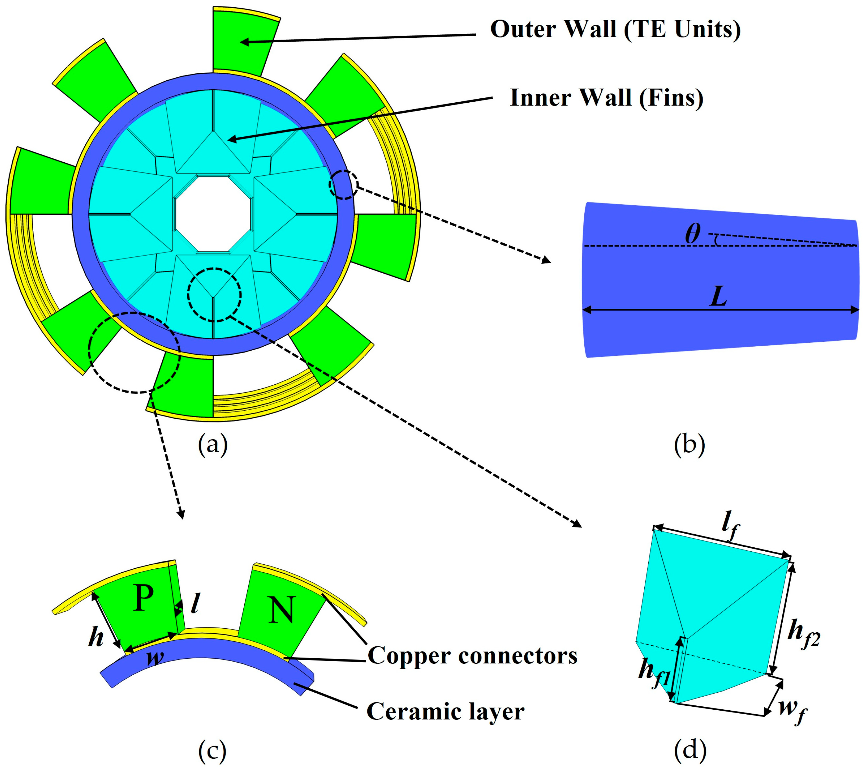
In order to further improve the efficiency of the existing ATEG in waste heat recovery, this paper presents the FF-CATEG three-dimensional physical device model, as seen in Figure 1a. High-temperature-resistant ceramic tubes are used as the heat conduction and structural support medium in the device, designed into an annular structure of axial gradient contraction, as presented in Figure 1b. In this design, bismuth telluride thermoelectric units are uniformly distributed on the outer wall of the annular ceramic, forming an array. This arrangement ensures that the top and bottom of the thermoelectric modules seamlessly connect to copper foils and the annular sleeve in an arc shape, as observed in Figure 1c. Perpendicular to the inner wall of the ceramic tube shell, a staggered topology structure, as illustrated in Figure 1d, is employed to establish the vortex generator fish-fin-like fin array, facilitating multi-dimensional contact between the fluid and fins. By reconstructing the local flow field to generate turbulent vortex structures, the residence time of the high-temperature fluid in the pipe can be significantly extended, therefore enabling sufficient heat exchange. The axially gradient-converging pipe designed in this paper can alleviate local stress concentration caused by thermal expansion and reduce structural fatigue. A large-diameter radial design is used in the inlet section of the pipe, forming low-velocity thermal mass, which effectively extends the heat exchange time. Simultaneously, relying on the convergent design of the outlet section accelerates the fluid after heat exchange, creating a high-speed, low-temperature-difference fluid heat source in the axial direction. This effectively overcomes the issue of end temperature difference decay caused by uneven velocity distribution within the cylindrical channel. Finally, the number of vortex generators (VGs) fish-fin-like fin arrays is optimized, thereby successfully reducing backpressure losses from high flow rates and consequently improving the overall net power output of FF-CATEG.

2.2. Heat Flow Energy Equation

As depicted in Figure 1, the cross-sectional area of the convergent annular pipe varies along the axial direction. To quantify the relationship between velocity and cross-sectional area variation, the continuity equation is applied to govern the conservation of mass flow rate:
ρ 1 A 1 v 1 = ρ 2 A 2 v 2
where v is the fluid velocity, subscripts 1 and 2 represent different physical quantities at different locations, and ρ is the fluid density. A = πr2, where r is the radius of the pipe, which is a function of the axial position, representing the pipe’s geometric boundary conditions, as given by Equation (2).
r x = R 1 R 1 R 2 L x
where R1 and R2 are defined as the inlet and outlet radii of the pipe, respectively. L refers to the pipe’s axial length, and x is the axial coordinate. In addition, based on the simplified form of the Navier–Stokes equation and incorporating the geometric boundary conditions of the convergent annular pipe [31,32], the axial momentum equation is given by Equation (3). Concurrently, the fluid must also adhere to the law of conservation of energy, which is expressed by Equation (4).
ρ v d v d x = d P d x + μ 1 r d d x r d v d r
( κ T ) = ρ c v T
P refers to the pressure, μ represents the dynamic viscosity of the working fluid, κ is the thermal conductivity, T is the inlet temperature, and c is the specific heat capacity.
An analytical framework for the laminar flow and heat transfer in a convergent annular pipe is established with the above theoretical model. To accurately capture turbulent flow behavior at high Reynolds numbers, the Renormalization Group-based (RNG) k-ε turbulence model is employed under conditions of elevated flow velocity [33,34,35]. Built upon the energy conservation equation, this model further describes how energy is transferred and transformed under turbulent conditions by capturing the interaction between turbulent kinetic energy k and its dissipation rate ε. The detailed governing equations are given by Equations (5) and (6):
t ( ρ k ) + x i ( ρ k v i ) = x j [ α k μ e k x j ] + H b H k Z M ρ ε
t ( ρ ε ) + x i ( ρ ε v i ) = x j [ α k μ e ε x j ] C 3 ε ρ ε 2 k R ε + C 1 ε ε k ( C 3 ε H b + H k )
where α is the expansion coefficient, αk denotes the turbulent kinetic energy produced by gas expansion, while ∂k and ∂ε represent the inverse effective Prandtl numbers associated with turbulent kinetic energy k and dissipation rate ε, respectively. The spatial coordinates in multi-dimensional space are described using xi and xj. The velocity component vi denotes the fluid velocity in the i-th directional axis. Hb indicates the turbulent kinetic energy induced by buoyancy effects, whereas Hk corresponds to the energy generated by the mean velocity gradient. The term ZM accounts for the influence of fluctuating dilatation on turbulent kinetic energy. The empirical constants C1ε, C2ε, and C3ε are introduced to fine-tune the model’s predictive accuracy. Rε refers to the eddy viscosity coefficient, which reflects the viscous effects in turbulence.
Subsequently, the governing mechanisms of thermoelectric coupling are analyzed. In thermoelectric modeling, the heat flux and charge continuity equations are given by:
ρ c T t + q = q ˙
J + D t = 0
where q ˙ is the volumetric heat generation rate, q is the vector of heat flux, J represents the current density vector, and D represents the electric displacement vector. The thermoelectric constitutive equations are introduced [36,37], as shown in Equations (9)–(11):
q = T [ α ] J [ κ ] T
J = [ σ ] ( E [ α ] T )
E = φ
[α] represents the Seebeck coefficient matrix, [κ] denotes the thermal conductivity matrix, [σ] corresponds to the electrical conductivity matrix, the vector E indicates the electric field intensity, while φ refers to the electric scalar potential. By combining the thermoelectric constitutive equations with the conservation equations and substituting Equations (9)–(11) into Equations (7) and (8), we obtain:
ρ c T t + ( T [ α ] J ) ( [ α ] T ) = q ˙
[ ε ] φ t + ( [ σ ] [ α ] T ) + ( [ σ ] φ ) = 0
[ε] denotes the permittivity matrix. In the final step, the coupled thermoelectric equations are expressed in the following form:
( T α J ) ( λ T ) = q ˙
( σ α T ) + ( σ φ ) = 0

2.3. Output Performance Characterization

The Reynolds number (Re) is a dimensionless parameter used to determine the flow state and study the FF-CATEG device. It is crucial in thermoelectric systems involving fluid motion, being is expressed as:
R e = ρ V D a μ
where Da is the average diameter of the convergent annular pipe, and V is the inlet velocity of the gas. From Equation (16), it is evident that the Reynolds number rises as the thermal gas flow velocity increases. With higher flow speeds, the flow path experiences an increase in frictional resistance, leading to greater backpressure power loss Pl, which can be expressed as:
P l = ( P 1 P 2 ) m ρ
where P1 and P2 denote the inlet and outlet pressures, respectively, with m denoting the associated gas mass flow rate. Consider a thermoelectric power generation single element without interface electrical and thermal resistance. The internal resistance Rin of the device is equal to the material’s electrical resistance RTE. Given the current I, the output voltage Vo and output power P of the device can be expressed as:
P = I V o c I 2 R i n
In the equation, Voc is the open-circuit voltage of the device, which depends on the Seebeck coefficient of the material and the temperature gradient across the device ends, defined as:
V o c = N ( S p S n ) ( T h T c )
N is the number of thermocouples, Sp and Sn represent the Seebeck coefficients of the P/N-type materials, respectively. Th and Tc stand for the temperatures at the high-temperature and low-temperature sides, respectively. To obtain the peak output power Po, the external load resistance should be matched to the internal resistance Rin of the device.
P o = V o c 2 4 R i n
Accordingly, Equations (17) and (20) are employed to compute the net power Pn and the corresponding conversion efficiency η:
P n = P o P l
η = P o P o + Q c
The heat flow Qc entering the hot side in Equation (22) can be expressed as:
Q c = m c ( T i T o )
Ti and To correspond to the input and output temperatures of the hot gas, and c is used to express the specific heat capacity of the gas.

3. Model Simulation

3.1. Model Construction

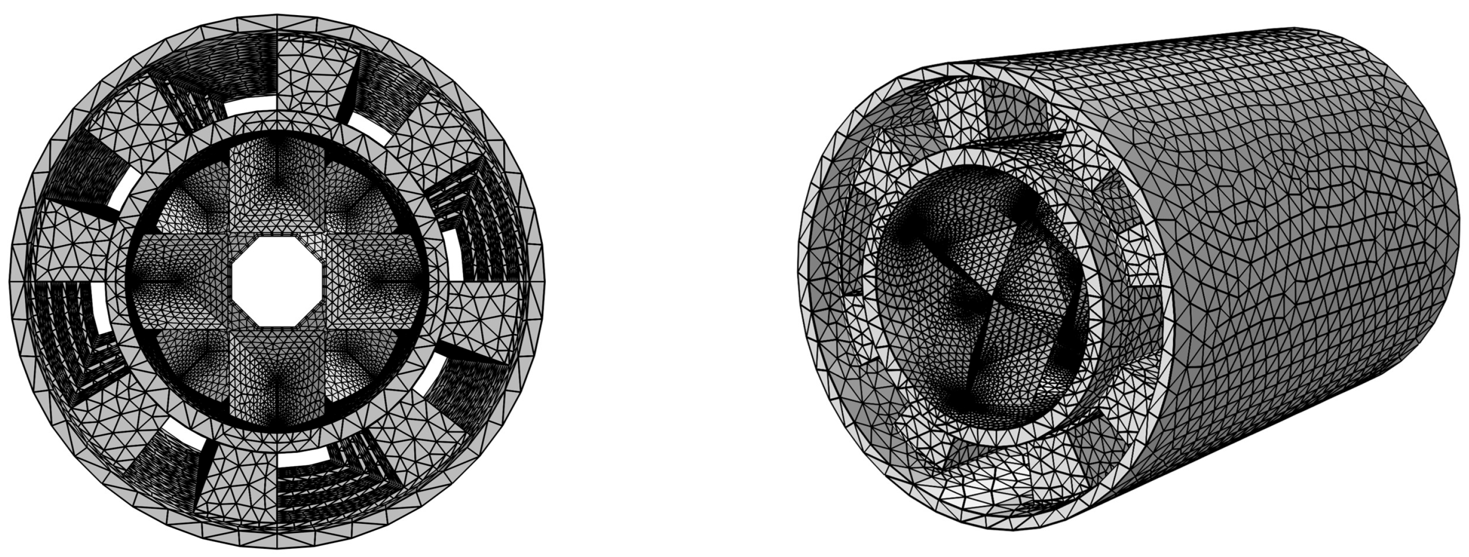
Based on the structural characteristics of the FF-CATEG device and the energy transfer theory, a thermal-flow-electric multi-physics coupling simulation model is constructed using the finite element method in COMSOL Multiphysics 6.1 software. The focus is on exploring the energy conversion coupling mechanism of high-temperature exhaust gas flow and heat transfer characteristics in a convergent annular pipe. Firstly, a three-dimensional geometric model of the axial gradient convergent tube shell, staggered VG fish-fin-like fin array, and circumferentially symmetric bismuth telluride thermoelectric module is reconstructed using parametric modeling techniques. The length of the convergent annular pipe is 65 mm, the inlet diameter is 30 mm, the outlet diameter is 22 mm, and the diameter contraction angle is θ. Detailed geometric parameters and physical properties are shown in Table 2. Twenty-four fins of fixed dimensions were arranged in a staggered, vertical pattern uniformly distributed inside the pipe. Subsequently, multi-scale meshing strategies, such as boundary layer refinement and interface transition layer optimization, were employed to balance computational accuracy and efficiency, as depicted in Figure 2. Specifically, unstructured tetrahedral elements were employed to discretize the computational domain, providing the flexibility required for the complex geometry of the staggered fins and convergent pipe. A grid independence study was conducted to ensure the reliability of the simulation results. Three mesh systems with different element numbers were tested: Coarse (558,950 elements), Medium (1,238,598 elements), and Fine (3,498,374 elements). The comparison revealed that the deviation in the net output power between the Medium and Fine meshes was less than 1.2%. Consequently, the Medium mesh system was adopted for all subsequent simulations to strike an optimal balance between computational accuracy and efficiency. Next, key boundary conditions such as the velocity v of the hot gas entering the pipe, the hot end temperature field Th, and the cold end temperature field Tc are defined. Specific parameters are shown in Table 3.

3.2. Angle Optimization

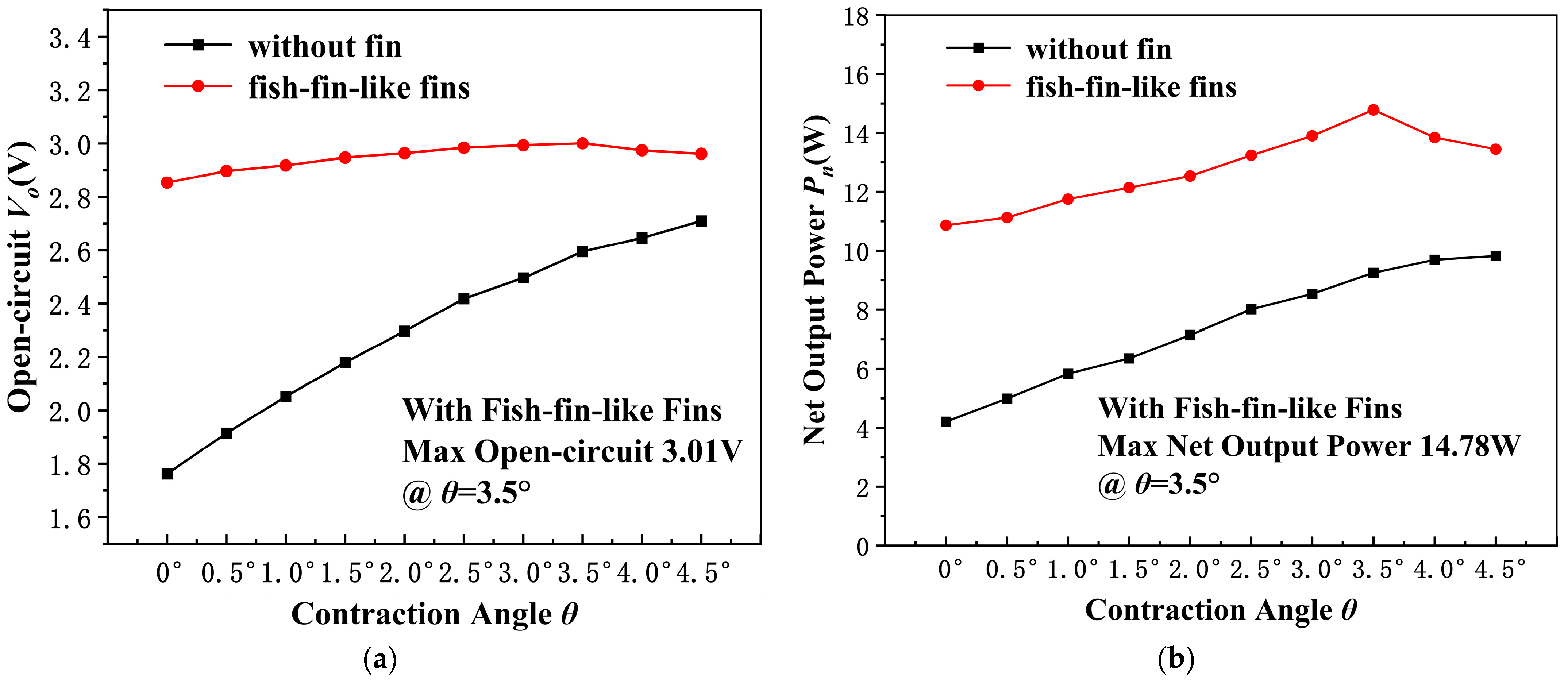
In order to explore the optimal contraction angle of the convergent annular pipe, based on the simulation model created in Section 3.1, 30 pairs of thermocouple blocks were used. The performance of the convergent annular thermoelectric generator (CATEG) without fins and with fish-fin-like fins is compared and analyzed under different contraction angles θ, with the hot gas temperature set to 623.15 K and the inlet velocity to 5 m/s. Figure 3a shows the variation in open-circuit voltage with the contraction angle of the pipe for two fin structures. The results show that as θ increases from 0° to 4.5°, the open-circuit voltage of both structures increases nonlinearly, with the finned structure consistently exhibiting significantly higher voltage than the non-finned structure. Figure 3b further presents the response of net output power for the two fin structures with respect to the contraction angle. The trend of net power increase for the non-finned structure is generally consistent with its open-circuit voltage. However, for the finned system, the net power reaches a peak of 14.78 W at a contraction angle of 3.5°, showing an increase of 36.1% compared to the case with no contraction angle. Overall comparison shows that the fish-fin-like fin system exhibits better output performance than the non-finned system. Concurrently, the pipe contraction increases the flow velocity and enhances heat transfer. However, when the contraction angle exceeds 3.5°, boundary layer separation causes a significant increase in backpressure loss, leading to a decrease in efficiency. Therefore, there exists an optimal contraction angle that can both increase the flow velocity and control pressure losses, consequently enhancing the heat transfer effect.

4. Results and Discussion

4.1. Experimental Setup

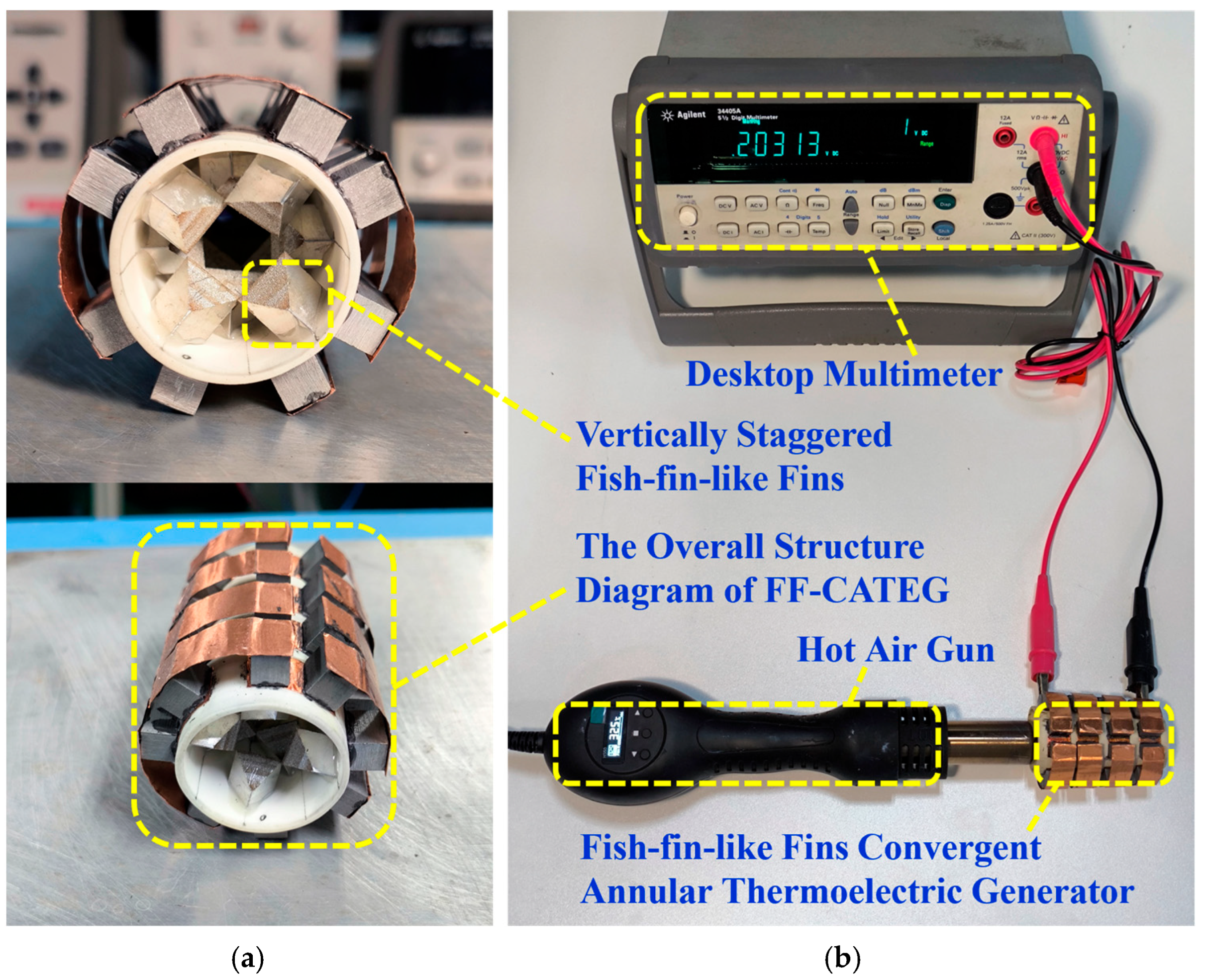
To verify the effectiveness of the proposed structure, the FF-CATEG device was fabricated, and an experimental testing platform was established, as presented in Figure 4. Figure 4a displays the specific structure of the FF-CATEG device, which consists of three main components: 24 fish-fin-like fins, a convergent annular ceramic pipe, and 16 pairs of P/N-type thermocouple blocks. The thermocouple blocks are electrically connected in series through copper strips, utilizing high thermal conductivity conductive carbon glue to bond the copper strips to the thermocouples. In parallel, the copper strip on the outer side of the pipe and the fin on the inner side of the pipe were joined by a high thermal conductivity and electrically insulating two-component epoxy resin, establishing an efficient thermal conduction path. Figure 4b shows the experimental testing platform of the system. The thermal input of the system is provided by a heat gun, which controls the temperature in the range of Th = 413–623 K and the airflow velocity between v = 1–15.7 m/s. The testing was conducted in a standard laboratory environment, with the ambient temperature stabilized at 293 K and the relative humidity controlled at 50%. Re is precisely adjusted by varying the thermal input temperature and airflow velocity parameters. The open-circuit voltage under steady-state heat exchange of the system was recorded. Table 4 presents the detailed material parameters used in the experiment.
To ensure the reliability of the experimental data, precise control and measurement instruments were employed. The high-temperature fluid was generated by a digital hot air gun with PID control, which provided a stable heat source with adjustable temperature (Th) and flow velocity (v). The electrical parameters (open-circuit voltage and internal resistance) were measured using a high-precision 5½ digit desktop multimeter (Agilent 34405A, Agilent Technologies (China) Co., Ltd., Beijing, China). The key specifications and accuracies of the experimental setup are listed in Table 5. The experimental uncertainty was evaluated using the root-sum-square (RSS) method. Considering the control stability of the heat source and the measurement precision of the multimeter, the maximum relative uncertainty for the output power is estimated to be approximately 3.6%, ensuring the validity of the results.

4.2. Temperature Characteristics

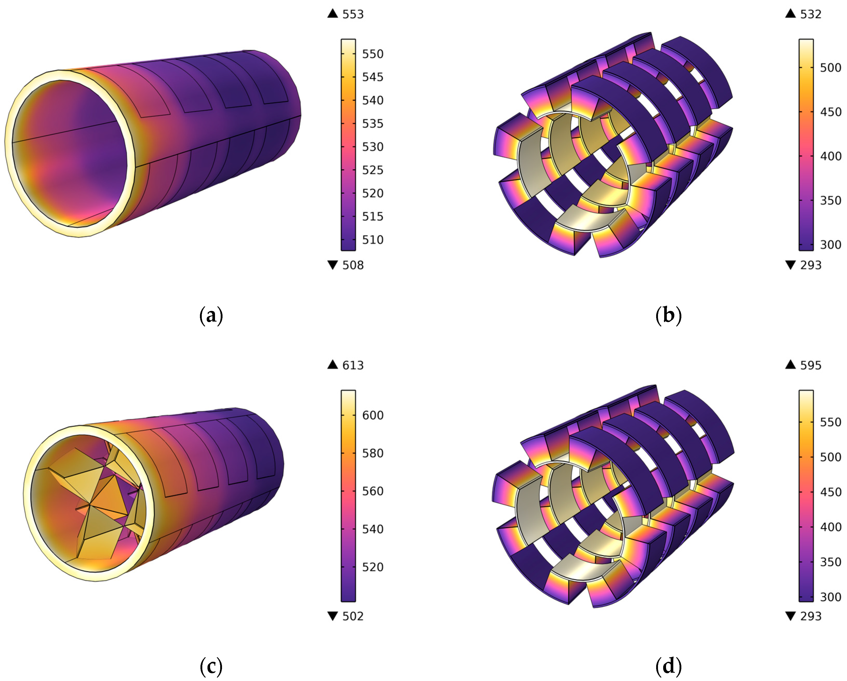
To evaluate how fins influence the thermoelectric efficiency of the system, a multi-physics coupling model of flow, heat, and electricity is used for simulation. The temperature field distribution of the pipe wall and thermocouple with and without the fin structure was obtained, as presented in Figure 5. It is evident that the temperature gradient across the finned pipe is considerably greater than that of the pipe without fins. The temperature difference across the thermally measured pipe increased from a maximum of 45 K to 111 K, representing an increase of 147%. The effective heat exchange area is significantly increased through geometric extension by the fins, prolonging the residence time of the high-temperature fluid on the heat transfer surface. This allows the system to maintain a higher hot-end temperature and a larger temperature difference, directly enhancing the thermoelectric conversion driving force. Figure 5c and Figure 5d, respectively, display the thermal distribution of the thermocouple with and without fins. Thermodynamic monitoring results indicate that after the fins are introduced, the hot-end undergoes a continuous temperature increase, with the temperature rising from 532 K to 595 K, an increase of 11.8%. This indicates that the vertically arranged fins periodically disrupt the flow boundary layer, forcing the high-temperature fluid to directly impact the surface of the TEG module. This mechanism not only improves the effective thermal contact efficiency between the TEG hot-end and the fluid but also establishes an energy transfer channel with low thermal contact resistance.

4.3. Power and Efficiency

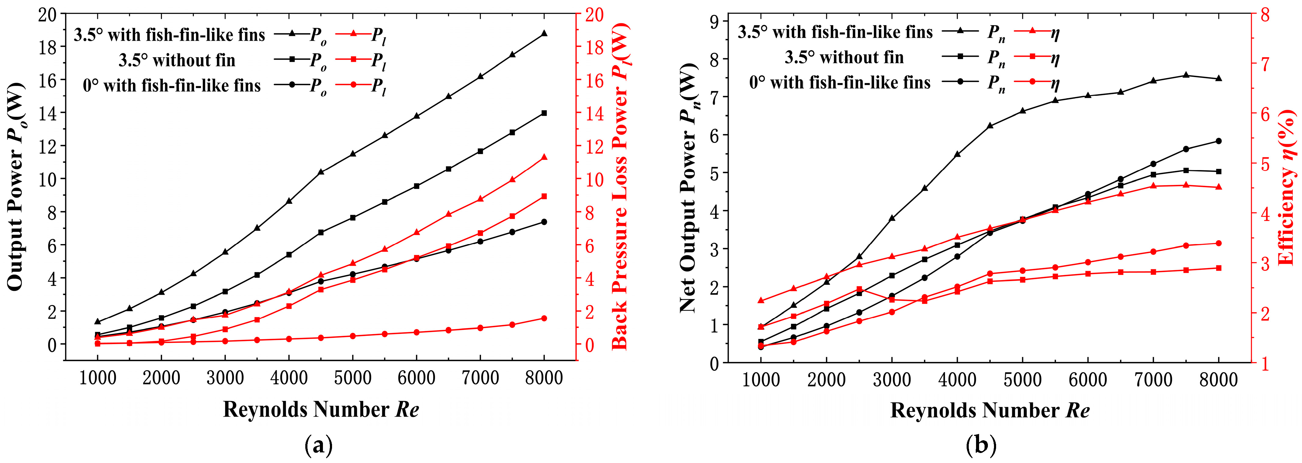
Next, this paper will use Re as the reference flow parameter. By adjusting the flow state and combining the net power Pn and thermoelectric conversion efficiency η as dual evaluation indicators, the effects of fish-fin-like fins and convergent pipe on the thermoelectric coupling performance will be analyzed. Figure 6a shows the simulation trends of output power and loss efficiency for the three devices: FF-CATEG, CATEG, and FF-ATEG. It is observed from the data that both the output power Po and loss power Pl of the three devices are positively correlated with Re. Although FF-CATEG has the highest loss power, as displayed in Figure 6b, Pn is significantly higher than the other two systems and reaches its peak at Re = 7500. Simultaneously, the efficiency η of all three systems exhibits a similar increasing trend, with FF-CATEG maintaining a higher efficiency than the other two systems. This indicates that the presence of convergent pipe and fins forces the fluid to flow along a tortuous path. This arrangement not only increases heat transfer opportunities but also enhances the spatiotemporal continuity of the fluid-solid contact, as a result improving energy extraction efficiency.
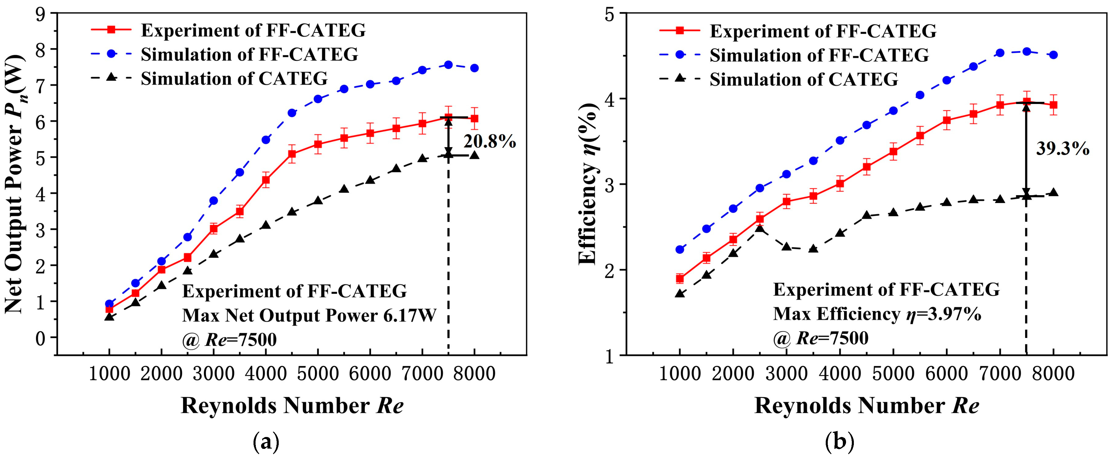
Figure 7 compares the performance differences in net output power and conversion efficiency between the FF-CATEG device and the CATEG device. In Figure 7a, the net output power obtained from experimental measurements is explicitly compared with the simulation results to verify the model’s accuracy. It shows that the experimental Pn of the FF-CATEG significantly increased from 0.78 W to 6.17 W, which is 20.8% higher than that of the CATEG simulated. The experimental and simulation results of FF-CATEG are in good agreement when Re < 3000, but the difference becomes more significant thereafter. This discrepancy is primarily attributed to the fact that under strong turbulence conditions, vortex instability induces flow separation and friction at the fluid-solid interface, resulting in elevated energy dissipation. In contrast, the CATEG simulation results persistently lag, highlighting the inefficiency of the CATEG configuration in energy capture at high flow velocities. Figure 7b further shows that the conversion efficiency of the FF-CATEG experiment reaches its peak at 3.97% when Re = 7500, while the peak efficiency of CATEG is only 2.85%, representing an improvement of 39.3%. Comprehensive analysis shows that the superior performance of FF-CATEG is attributed to the convergent pipe geometry and turbulence-optimized design, which enable high power output and efficiency at medium to high Re. In contrast to the rigid flow channel structure and inadequate dynamic response of traditional ATEGs, FF-CATEG is better suited to complex flow conditions.
To clearly demonstrate the performance superiority of the proposed design, a detailed comparison of the key performance indicators among the optimized configurations at the optimal Reynolds number (Re = 7500) is presented in Table 6. In this comparison, the optimized CATEG is selected as the high-performance benchmark. As shown in the table, the proposed FF-CATEG achieves the highest output performance. Specifically, its experimental conversion efficiency reaches 3.97%, which represents a significant improvement of 39.3% compared to the CATEG benchmark (2.85%). This confirms that the synergistic effect of the convergent channel and the staggered fish-fin structures effectively enhances the overall energy conversion capability.

4.4. Power Optimization

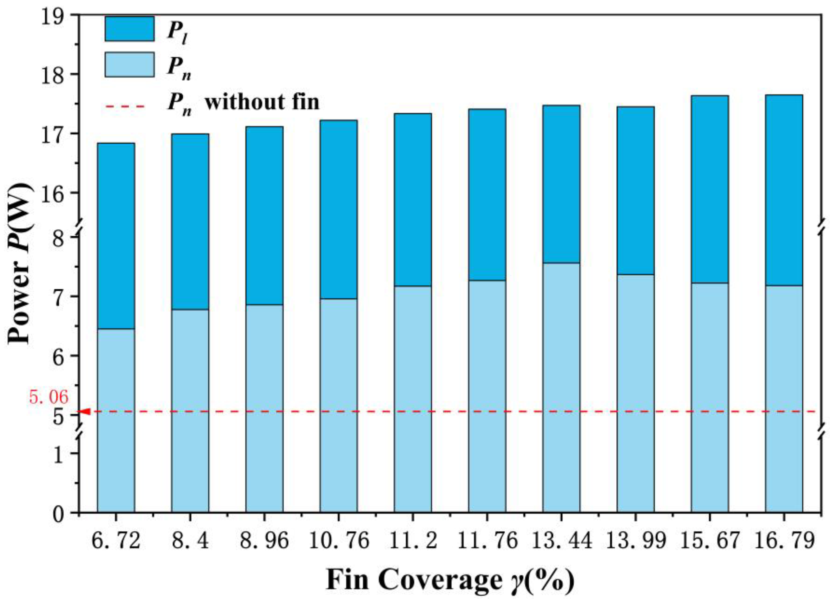
To achieve continuous improvement in the performance of FF-CATEG devices, the optimization of fin parameters is particularly essential. This section investigates the impact of different fin coverage ratios γ on Po and Pn. As shown in Figure 8, there is a significant correlation between the fin coverage ratio γ and the system power parameters Po and Pn. The data shows that as γ increases, Pn exhibits a unimodal characteristic, first rising and then gradually decreasing. The peak power of 7.56 W occurs at γ = 13.44%, which is a 49.4% improvement compared to the finless convergent system (5.06 W, as indicated by the dashed line). Notably, Pn is consistently greater compared to the system without fins even under non-optimal γ conditions, indicating that the fin configuration has a universally beneficial effect on efficiency.

5. Conclusions

This study proposes and validates a novel convergent annular TEG energy harvester equipped with a staggered fish-fin-like array. Specifically, the design innovatively integrates an axial convergent annular pipe with staggered fish-fin-like fins. It also employs a circumferentially symmetrical annular distribution of thermocouple arrays closely attached to the outer wall of the pipe, resulting in the design of an efficient waste heat energy harvester. The experimental results show that Pn of the FF-CATEG can reach up to 6.17 W with a conversion efficiency of 3.97% when the optimized convergent pipe has a contraction angle of θ = 3.5° under the condition of Re = 7500. This represents a 20.8% and 39.3% improvement over the CATEG, respectively. Through the collaborative optimization of structural-flow field mechanism, the device’s power output and conversion efficiency are effectively improved. This work provides a valuable reference for the efficient capture and conversion of turbulent energy.

Author Contributions

N.W.: Writing—review and editing, Funding acquisition; Z.Z.: Software, Data curation, Writing—original draft; J.L.: Conceptualization; J.C.: Formal analysis; H.J.: Methodology; B.D.: Project administration; D.Z.: Supervision, Resources and Visualization. All authors have read and agreed to the published version of the manuscript.

Funding

This work was supported in part by National Natural Science Foundation of China under Grant 62474112, in part by Shanghai Pujiang Programme under Grant 23PJD066, and in part by the National Science and Technology Major Project from Minister of Science and Technology, China, under Grant 2018AAA0103100.

Data Availability Statement

The original contributions presented in this study are included in the article. Further inquiries can be directed to the corresponding author.

Conflicts of Interest

The authors declare no conflicts of interest.

Nomenclature

cSpecific heat capacity (J/(kg⋅K))
θConvergence angle of the pipeline (deg)
P1Inlet pressure (Pa)
P2Outlet pressure (Pa)
VocOpen-circuit voltage (V)
TTemperature (K)
ReReynolds number
mMass flow rate (g/s)
DDiameter of the pipe (m)
RRadial (m)
LPipeline length (m)
hHeight (m)
wWidth (m)
lLength (m)
PoOutput power (W)
PlPower loss (W)
PnNet power (W)
QHeat flow, W
ACross-sectional area (m2)
RinInternal resistance (Ω)
vVelocity (m/s)
xAxial coordinate (m)
Subscripts
pP-type thermoelectric leg
nN-type thermoelectric leg
eEffective
fFin
Greek symbols
αCoefficient of thermal expansion (1/K)
φElectric potential (V)
κThermal conductivity (W/(m⋅K))
ρFluid density (kg/m3)
εDissipation rate (m2/s3)
σElectrical conductivity (S/m)
ηEfficiency (%)
μDynamic viscosity (Pa⋅s)
Abbreviations
VGVortex generators
TEGThermoelectric generator
FTEGFlat-plate thermoelectric generator
ATEGAnnular thermoelectric Generator
CATEGConvergent annular thermoelectric generator

References

  1. Poure, P.; Huq, M. Thermoelectric generator for waste energy recovery in transport. Energies 2022, 15, 8006. [Google Scholar] [CrossRef]
  2. Singh, D.V.; Pedersen, E. A review of waste heat recovery technologies for maritime applications. Energy Convers. Manag. 2016, 111, 315–328. [Google Scholar] [CrossRef]
  3. Riahi, A.; Ben Haj Ali, A.; Fadhel, A.; Guizani, A.; Balghouthi, M. Performance investigation of a concentrating photovoltaic thermal hybrid solar system combined with thermoelectric generators. Energy Convers. Manag. 2020, 205, 112377. [Google Scholar] [CrossRef]
  4. Mejri, M.; Romanjek, K.; Mouko, H.I.; Thimont, Y.; Oulfarsi, M.; David, N.; Malard, B.; Estournès, C.; Dauscher, A. Reliability investigation of silicide-based thermoelectric modules. ACS Appl. Mater. Interfaces 2024, 16, 8006–8015. [Google Scholar] [CrossRef] [PubMed]
  5. Sun, M.; Liao, X. Theoretical and experimental investigation of a photoelectric-thermoelectric integrated power generator filled by Al layer. IEEE Trans. Electron Devices 2022, 69, 2462–2468. [Google Scholar] [CrossRef]
  6. Kabir, M.; Habiba, U.E.; Iqbal, M.Z.; Shafiq, M.; Farooqi, Z. Industrial pollution and its impacts on ecosystem: A Review. Biosci. Res. 2020, 17, 1364–1372. [Google Scholar]
  7. Fernández-Yáñez, P.; Romero, V.; Armas, O.; Cerretti, G. Thermal management of thermoelectric generators for waste energy recovery. Appl. Therm. Eng. 2021, 196, 117291. [Google Scholar] [CrossRef]
  8. Hendricks, T.; Caillat, T.; Mori, T. Keynote review of latest advances in thermoelectric generation materials, devices, and technologies 2022. Energies 2022, 15, 7307. [Google Scholar] [CrossRef]
  9. d’Angelo, M.; Galassi, C.; Lecis, N. Thermoelectric Materials and Applications: A Review. Energies 2023, 16, 6409. [Google Scholar] [CrossRef]
  10. Yan, Q.; Kanatzidis, M.G. High-performance thermoelectrics and challenges for practical devices. Nat. Mater. 2022, 21, 503–513. [Google Scholar] [CrossRef] [PubMed]
  11. Dashevsky, Z.; Jarashneli, A.; Unigovski, Y.; Dzunzda, B.; Gao, F.; Shneck, R.Z. Development of a high performance gas thermoelectric generator (TEG) with possible use of waste heat. Energies 2022, 15, 3960. [Google Scholar] [CrossRef]
  12. Khalil, H.; Hassan, H. Enhancement thermoelectric generators output power from heat recovery of chimneys by using flaps. J. Power Sources 2019, 443, 227266. [Google Scholar] [CrossRef]
  13. Lysko, V.V.; Konstantynovych, I.A.; Havryliuk, M.V.; Rusnak, O.S. Experimental studies on the parameters of thermoelectric generator energy converters with different height of legs. J. Thermoelectr. 2024, 4, 50–60. [Google Scholar] [CrossRef]
  14. Alegria, P.; Catalán, L.; Araiz, M.; Erro, I.; Astrain, D. Design and optimization of thermoelectric generators for harnessing geothermal anomalies: A computational model and validation with experimental field results. Appl. Therm. Eng. 2024, 236, 121364. [Google Scholar] [CrossRef]
  15. Gou, X.; Yang, S.; Xiao, H.; Ou, Q. A dynamic model for thermoelectric generator applied in waste heat recovery. Energy 2013, 52, 201–209. [Google Scholar] [CrossRef]
  16. Eidelman, E.D. Thermoelectric effect and a thermoelectric generator based on carbon nanostructures: Achievements and prospects. Phys.-Usp. 2021, 64, 535–557. [Google Scholar] [CrossRef]
  17. Manikandan, S.; Kaushik, S.C. Energy and exergy analysis of solar heat pipe based annular thermoelectric generator system. Sol. Energy 2016, 135, 569–577. [Google Scholar] [CrossRef]
  18. Cao, Y.; Abu-Hamdeh, N.H.; Moria, H.; Asaadi, S.; Alsulami, R.; Sadighi Dizaji, H. A novel proposed flexible thin-film solar annular thermoelectric generator. Appl. Therm. Eng. 2021, 183, 116245. [Google Scholar] [CrossRef]
  19. Jang, H.; Kim, J.B.; Stanley, A.; Lee, S.; Kim, Y.; Park, S.H.; Oh, M.W. Fabrication of skutterudite-based tubular thermoelectric generator. Energies 2020, 13, 1106. [Google Scholar] [CrossRef]
  20. Li, X.; Chen, L.; Yu, Z.; He, L.; Lee, J. Performance test and prediction on a radial π-type annular thermoelectric generator directly exposed to an automotive pipe for waste heat recovery. Appl. Therm. Eng. 2024, 251, 123621. [Google Scholar] [CrossRef]
  21. He, H.; Xie, Y.; Zuo, Q.; Chen, W.; Shen, Z.; Ma, Y.; Zhang, H.; Zhu, G.; Ouyang, Y. Optimization analysis for thermoelectric performance improvement of biconical segmented annular thermoelectric generator. Energy 2024, 306, 132397. [Google Scholar] [CrossRef]
  22. Yang, W.; Xu, A.; Zhu, W.; Li, Y.; Shi, Y.; Huang, L.; Li, H.; Lin, W.; Xie, C. Performance improvement and thermomechanical analysis of a novel asymmetrical annular thermoelectric generator. Appl. Therm. Eng. 2024, 237, 121804. [Google Scholar] [CrossRef]
  23. Ma, T.; Lu, X.; Pandit, J.; Ekkad, S.V.; Huxtable, S.T.; Deshpande, S.; Wang, Q.-W. Numerical study on thermoelectric-hydraulic performance of a thermoelectric power generator with a plate-fin heat exchanger with longitudinal vortex generators. Appl. Energy 2017, 185, 1343–1354. [Google Scholar] [CrossRef]
  24. Yang, W.; Jin, C.; Zhu, W.; Li, Y.; Zhang, R.; Huang, L.; Xie, C.; Shi, Y. Taguchi optimization and thermoelectrical analysis of a pin fin annular thermoelectric generator for automotive waste heat recovery. Renew. Energy 2024, 220, 119628. [Google Scholar] [CrossRef]
  25. Candolfi, C.; El Oualid, S.; Lenoir, B.; Caillat, T. Progress and perspectives in thermoelectric generators for waste-heat recovery and space applications. J. Appl. Phys. 2023, 134, 100901. [Google Scholar] [CrossRef]
  26. El Oualid, S.; Kosior, F.; Span, G.; Mehmedovic, E.; Paris, J.; Candolfi, C.; Masschelein, P.; Lenoir, B. Influence of thermoelectric properties and parasitic effects on the electrical power of thermoelectric micro-generators. Energies 2022, 15, 3746. [Google Scholar] [CrossRef]
  27. Pan, Y.; Le, C.; He, B.; Watzman, S.J.; Yao, M.; Gooth, J.; Wang, J.P.; Fu, C.; Snyder, G.J.; Felser, C. Giant anomalous Nernst signal in the antiferromagnet YbMnBi2. Nat. Mater. 2022, 21, 203–209. [Google Scholar] [CrossRef]
  28. Wang, N.; Li, J.; Wu, Y.; Zhang, L.; Xu, S.; Liu, Y.; Jia, H.; Wang, G. Optimized design of vortex generator-like finned thermoelectric generator for waste heat energy harvesting. Appl. Therm. Eng. 2025, 278, 127062. [Google Scholar] [CrossRef]
  29. Ivanochko, M.M.; Konstantynovych, I.A.; Kadelnyk, K.O. Design of a portable universal thermoelectric generator. J. Thermoelectr. 2024, 1–2, 78–89. [Google Scholar] [CrossRef]
  30. Antonova, E.E.; Looman, D.C. Finite elements for thermoelectric device analysis in ANSYS. In ICT 2005. 24th International Conference on Thermoelectrics; IEEE: Clemson, SC, USA, 2005; pp. 215–218. [Google Scholar]
  31. El Oualid, S.; Kogut, I.; Benyahia, M.; Geczi, E.; Kruck, U.; Kosior, F.; Masschelein, P.; Candolfi, C.; Dauscher, A.; Koenig, J.D.; et al. High Power Density Thermoelectric Generators with Skutterudites. Adv. Energy Mater. 2021, 11, 2100580. [Google Scholar] [CrossRef]
  32. Sanin-Villa, D.; Monsalve-Cifuentes, O.D. A methodological approach of predicting the performance of thermoelectric generators with temperature-dependent properties and convection heat losses. Energies 2023, 16, 7082. [Google Scholar] [CrossRef]
  33. Tian, M.W.; Mihardjo, L.W.W.; Moria, H.; Asaadi, S.; Sadighi Dizaji, H.; Khalilarya, S.; Nguyen, P.T. A comprehensive energy efficiency study of segmented annular thermoelectric generator; thermal, exergetic and economic analysis. Appl. Therm. Eng. 2020, 181, 115996. [Google Scholar] [CrossRef]
  34. Madar, N.; Shpack, H.; Kingma, D.; Sadia, Y.; Gelbstein, Y. Optimizing the thermoelectric performance of (GeTe)0.962(Bi2Te3)0.038 alloy through anisotropic texturing. J. Alloys Compd. 2025, 1040, 183334. [Google Scholar] [CrossRef]
  35. Teffah, K.; Zhang, Y.; Mou, X.L. Modeling and experimentation of new thermoelectric cooler–thermoelectric generator module. Energies 2018, 11, 576. [Google Scholar] [CrossRef]
  36. Ivanov, D.K.; Ivanov, K.G.; Uryupin, O.N. Strip thermoelectric generator made of carbon fiber. Semiconductors 2024, 57, 398–400. [Google Scholar] [CrossRef]
  37. Nonthakarn, P.; Ekpanyapong, M.; Nontakaew, U.; Bohez, E. Design and optimization of an integrated turbo-generator and thermoelectric generator for vehicle exhaust electrical energy recovery. Energies 2019, 12, 3134. [Google Scholar] [CrossRef]
Figure 1. Schematic of the FF-CATEG overall structure. (a) Overall structure; (b) pipe structure; (c) thermocouple unit; (d) fish-fin-like fin.
Energies 19 00762 g001
Figure 2. FF-CATEG finite element cell partitioning model.
Energies 19 00762 g002
Figure 3. (a) Variation in open-circuit voltage with contraction angle for finned and non-finned systems; (b) variation in net output power with contraction angle for finned and non-finned systems.
Energies 19 00762 g003
Figure 4. Structural diagram of the FF-CATEG device and experimental platform construction: (a) Structural details of the FF-CATEG; (b) Experimental setup with hot air gun and desktop multimeter.
Energies 19 00762 g004
Figure 5. Temperature distribution of the heat exchanger: (a,b) inner wall without and with fins; (c,d) thermocouples without and with fins.
Energies 19 00762 g005
Figure 6. Simulation comparison chart of 3.5° finned, 3.5° non-finned, and 0° finned systems: (a) output power and loss power; (b) net output power and conversion efficiency.
Energies 19 00762 g006
Figure 7. Simulated and experimental outcomes of FF-CATEG versus CATEG: (a) net output power; (b) thermoelectric conversion efficiency.
Energies 19 00762 g007
Figure 8. Power optimization studies of different coverage rates of fins.
Energies 19 00762 g008
Table 1. Recent comparative review and summary of annular thermoelectric generators.
ReferencesContributionsLimitations
Jang et al. [19]Designed a tubular TEG utilizing skutterudite, using a modified resistance welding (MRW) technique to significantly reduce the specific contact resistance and enhance power density.The monolithic structure results in substantial contact thermal resistance and severely lacks mechanical flexibility.
Li et al. [20]Proposed a radially uniform cross-section π-type ATEG. The open-circuit voltage of a single-stage ATEG module reached 229 mV under conditions of air cooling, an exhaust temperature of 423.15 K, and a flow rate of 9 m3/min.The study did not address the influence of hot-side flow velocity on the output parameters, nor did it include an analysis under varying temperature difference conditions.
He et al. [21]Proposed a biconical segmented annular TEG. The output power was increased by 145.7% while simultaneously reducing material costs by 60.2%.The study focused solely on the structural design of the thermoelectric modules, without investigating thermal flow parameters or strategies to enhance heat exchange.
Yang et al. [22]Proposed a new asymmetric ATEG structure. They revealed the compensation mechanism of asymmetric design for the material property differences.Lacking research on the impact mechanisms of fluid flow characteristics in the heat transfer process on power generation.
Ma et al. [23]Proposed a multi-scale topological design of plate-fin type longitudinal vortex generators (LVGs). The peak net power of 0.6 W and the peak thermal efficiency of 1.5% were achievedThe turbulence control efficiency of such plate-fin heat exchangers is relatively low.
Yang et al. [24]Proposed an integrated circular pin-fin ATEG through bionic thermal topology optimization. Ultimately an 18.7% increase in output power was achieved.There is still room for improvement in the local heat transfer enhancement mechanism, especially in terms of flow uniformity and vortex control capabilities.
Table 2. Key geometric dimensions of FF-CATEG.
ParameterMeaningValueUnit
l/w/hP-N junction dimensions (Length/width/height)0.01/0.007/0.007m
lf/wf/hf1/hf2Fin dimensions0.0096/0.006/0.0047/0.0085m
θPipe convergence angle3.5deg
LTotal pipe length0.065m
dxHeat exchanger tube wall thickness0.002m
dcCopper joint thickness0.0005m
Table 3. Input parameters and boundary conditions.
ParameterMeaningValueUnit
R1Inlet radius of the pipe0.015m
R2Outlet radius of the pipe0.011m
ThTemperature of incoming hot gas613.15K
TcAmbient temperature at inlet293.15K
vVelocity of hot gas flow14.5m/s
ρDensity of hot gas fluid0.66kg/m3
mRate of mass flow for hot gas5.45g/s
μDynamic viscosity of hot gas3.08 × 10−5Pa⋅s
cSpecific heat capacity of hot gas1.37kJ/(kg·K)
Table 4. Material properties of the FF-CATEG device.
ComponentsParametersValue
ThermocoupleThermal conductivity, κ1.6 W/(m·K)
Seebeck coefficient, S±2.0 × 10⁻⁴ V/K
Electrical resistivity, ρe9.0 × 10−6 Ω·m
Copper conductorThermal conductivity, κ403 W/(m·K)
Seebeck coefficient, S1.4 × 10−5 V/K
Electrical resistivity, ρe1.44 × 10−8 Ω·m
Alumina finsThermal conductivity, κ30 W/(m·K)
Electrical resistivity, ρe>1 × 10¹² Ω·m
Ceramic layerThermal conductivity, κ49.2 W/(m·K)
Table 5. Specifications and accuracies of experimental instruments.
ParameterInstrumentRangeAccuracy
Voltage (V)Agilent 34405A0–100 V±0.025%
Resistance (R)Agilent 34405A0–10 kΩ±0.05%
Temperature (Th)Digital hot air gun300–700 K±5 K
Velocity (v)Digital hot air gun1–20 m/s±0.1 m/s
Table 6. Performance comparison of different annular thermoelectric generator configurations at Re = 7500.
ConfigurationPipe StructureFin StructureMax Net Power (Pn)Efficiency (η)Enhancement (vs. CATEG)
CATEG(Benchmark)Convergent (θ = 3.5°)None5.11 W (Sim)2.85% (Sim)-
FF-ATEGStraight (θ = 0°)Staggered fins5.62 W (Sim)3.34% (Sim)+17.2%
FF-CATEG (Proposed)Convergent (θ = 3.5°)Staggered fins6.17 W (Exp)/7.56 W (Sim)3.97% (Exp)+39.3%
Disclaimer/Publisher’s Note: The statements, opinions and data contained in all publications are solely those of the individual author(s) and contributor(s) and not of MDPI and/or the editor(s). MDPI and/or the editor(s) disclaim responsibility for any injury to people or property resulting from any ideas, methods, instructions or products referred to in the content.