Article

Optimization-Based Energy Management of a Standalone Hybrid Power Plant Using a Hybrid IHEO–PSO Metaheuristic Framework

School of Engineering, Edith Cowan University, Joondalup, WA 6027, Australia
*
Author to whom correspondence should be addressed.
Energies 2026, 19(18), 4429; https://doi.org/10.3390/en19184429 (registering DOI)
Submission received: 13 August 2026 / Revised: 13 September 2026 / Accepted: 14 September 2026 / Published: 18 September 2026

Abstract

The current study combines solar photovoltaic (PV) power, energy storage batteries and wind power to propose a novel and effective method for energy management and optimisation of hybrid renewable energy systems. Optimising the management and coordination of many energy sources is becoming essential, as the world moves towards sustainable energy choices. This study seeks to improve system performance, reliability and operating costs, using a unique hybrid control and power management paradigm, the Improved Human Evolutionary Optimisation (IHEO) algorithm, presented as a novel optimisation method that balances energy flow, generation, storage and consumption. This study shows that the proposed model greatly improves the efficiency of the operation of hybrid systems. The optimisation’s main objective is to reduce the overall cost of energy production while maintaining a smart energy management system. In this context, the cost function accounts for energy losses during electricity distribution as well as the generation costs of solar, wind, and battery storage. By minimising energy losses and optimising power flow between energy sources (wind, solar), storage (battery) and load demand, this can be used to assess system performance. The applied approach ensures system stability, optimises the use of renewable energy sources and reduces the power imbalance. The improved effectiveness of the IHEO algorithm in this study in minimising energy losses, lowering operating costs and enhancing overall system efficiency is demonstrated by thorough comparison with conventional particle swarm optimisation (PSO). Further to this, the integration of MPPT with PV systems and the IHEO algorithm enhances energy extraction efficiency by dynamically optimising power flow, ensuring maximum output from renewable sources under varying environmental conditions. Additionally, the BESS charging current ripple is also reduced from ±15 A to ±3 A using the model applied in this study, confirming smoother and safer battery charging operation. The key novelty lies in using IHEO for global exploration to find the best solution and PSO for local refinement to improve battery coordination with renewables and smooth DC-link regulation, which is then compared with conventional WOA.

1. Introduction

1.1. Motivation and Context

Although the rapid decarbonisation of power systems is accelerating the deployment of large photovoltaic (PV) and wind plants, their intrinsic variability and limited controllability pose significant challenges for the security of supply, grid stability and market integration. Accordingly, utility-scale hybrid power plants (HPPs), where wind power, photovoltaic power and energy storage share a single connection to the grid and operate as a single asset, have emerged as a key tool to provide greater renewable penetration, with improved flexibility and more efficient use of existing grid infrastructure [1,2]. Recent reviews have emphasised that the long-term value of these plants is ultimately determined by their energy management system (EMS), which co-ordinates heterogeneous resources across multiple time scales and services [2]. Hybrid energy storage systEMS (HESSs) are increasingly used to provide both energy shifting and fast power balancing, combining batteries with high-power devices, such as ultracapacitors or supercapacitors [3,4,5]. Advanced EMS designs for photovoltaic–wind–battery plants have been proposed for grid-connected HPPs with multilevel converter interfaces, where nonlinear constrained optimisation is used to maximise battery efficiency and simultaneously track active and reactive power references [6]. More recent work extends this idea by embedding EMS into cascaded multilevel configurations and demonstrating further cost and emission reductions through improved supervisory control of battery storage in hybrid plants [7]. In parallel, coordinated EMS formulations for wind–solar microgrids with HESSs have shown that appropriate scheduling of fast and slow storage significantly improves reliability and reduces operating cost under uncertainty [8], while hybrid PV, wind, battery and fuel-cell systems with hybrid battery/supercapacitor storage confirm the importance of treating storage as a multi-time-scale resource rather than a single aggregated unit [4]. The research in [3] highlights that the effectiveness of HESS-based marine power systems depends not only on the storage configuration but also on the capability of the EMS to coordinate multiple energy sources under dynamic operating conditions. To implement these functions in practice, a wide spectrum of EMS strategies have been explored, ranging from rule-based and fuzzy-logic controllers to deterministic optimisation, model predictive control and metaheuristic approaches [9,10,11]. In addition to this, intelligent and hybrid schemes are becoming particularly prominent, where improved swarm-based algorithms and hybrid metaheuristics have been applied to grid-connected solar–wind–battery systems, achieving better cost and power-quality performance than conventional strategies. For example, improved grey wolf optimisation and improved particle swarm optimisation (PSO) have been used to derive operating strategies and multi-objective EMS formulations for hybrid plants and remote microgrids [12]. Capacity-optimal allocation and frequency-division energy management for hybrid battery/supercapacitor storage in PV systems demonstrate how appropriately designed EMS can simultaneously enhance grid-compliance and extend storage lifetime [5]. Research on home energy systems and hybrid power plants shows that energy management plays an important role in improving energy use, storage operation, and overall system performance [11,13].

1.2. Review of Previous Work

Recent HPP-oriented studies [14,15,16,17] further confirm that while sophisticated EMS frameworks can reduce cost, improve battery utilisation, and enhance grid services, they are often tailored to specific topologies and rely on a single optimisation paradigm. This makes performance strongly dependent on initialisation and parameter tuning and can limit robustness when the operating space is enlarged to utility-scale, standalone or weak-grid conditions. From a system-level perspective, EMS algorithms need to combine strong global search with fast local refinement to reliably find high-quality dispatch decisions for complex hybrid plants with multiple objectives—cost, reliability, ramp-rate control, and storage aging—under realistic renewable and load profiles. To date, optimised EMS approaches for solar battery microgrids have considered economic operation together with voltage stability and battery degradation costs, showing that storage-aware scheduling is important for practical microgrid operation [18]. Similarly, battery-degradation-aware EMS frameworks have shown how frequent charging and discharging can reduce BESS lifetime if the scheduling algorithm does not properly control storage stress [6]. Recent grid-connected HPP studies [19,20] show that optimal EMS design can improve renewable use and system stability when photovoltaic, wind and battery units are integrated through advanced converter structures. In both standalone and weak-grid conditions, the scheduling algorithm must simultaneously handle renewable uncertainty, load variation, DC-link regulation, Battery SOC limits, and power-quality constraints [19]. This increases the complexity of the optimisation problem and renders single-algorithm methods less reliable when the search space becomes highly nonlinear.
Recent studies have shown that PSO is beneficial for hybrid renewable energy systems, especially for sizing and energy management of stand-alone PV–wind and battery systems [21]. However, PSO on its own still face issue of getting trapped in local optima, depending too much on parameter settings and weaker performance when the system becomes nonlinear and dynamic [22]. On the other hand, research studies [23,24,25] on IHEO reported good search ability and better exploration in energy-related optimisation problems. Even so, IHEO use in standalone hybrid power plants is still very limited. Available studies on IHEO do not clearly address smooth battery SOC control, stable DC-link voltage, reduced oscillations, or lower-cost convergence than traditional control algorithms. Recent hybrid metaheuristic techniques have demonstrated improved convergence and solution quality for RESs. However, their application has been focused on component sizing, techno-economic optimisation, capacity allocation, or demand-side optimisation rather than dynamic PV-wind and battery dispatch [26]. The author developed a hybrid GWO-WOA algorithm for multi-objective sizing of sources including PV–wind and battery system based on levelised cost of energy and net present cost. However, the research study in [27] combines PSO-WOA for designing and sizing of a standalone renewable microgrid. Similarly, the study [28] presents GWO coupled with local search heuristics, which has already demonstrated the advantages of combining global exploration with local refinement in integrated energy system optimisation.
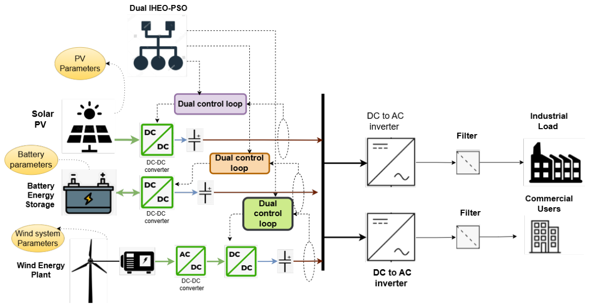
To deal with theses issues, this paper proposes a hybrid IHEO–PSO algorithm for energy management of a standalone hybrid power plant as shown in Figure 1. The main idea is to use the stronger search ability of IHEO together with the fast convergence of PSO. In this way, the proposed method aims to overcome the slow convergence, higher oscillations and weaker co-ordination that can appear in single algorithms. The proposed approach gives smoother SOC behaviour, better DC-link voltage regulation and lower convergence cost. This leads to the effective co-ordination of PV, wind and battery subsystems. Therefore, the novelty of the presented work does not lie merely in combining exploratory and exploitative optimisers, but in sequential integration of IHEO and PSO within the EMS oriented framework for operational PV–wind and BESS power coordination under battery and DC-link constraints.
The remainder of this paper is organised as follows: Section 2 presents the system description and modelling of the standalone hybrid power plant, including the mathematical models of the PV, wind and battery subsystems as well as the reliability equations adopted in the analysis. Section 3 describes the proposed hybrid IHEO–PSO energy management framework. Section 4 discusses the simulation results and comparative analysis. Finally, the paper ends with the conclusion, followed by the references.

2. System Description and Modelling

2.1. System Description and Architecture

A standalone hybrid renewable energy system consists of a photovoltaic (PV) generator, a wind energy conversion system (WECS), and a battery energy storage system (BESS) interconnected through power-electronic interfaces and a common DC link (or DC bus) as shown in Figure 1. The PV and wind subsystems inject power to the DC link through unidirectional conversion stages, while the BESS connects through a bidirectional converter to balance generation–load mismatch, support DC-link voltage regulation, and enforce energy constraints (e.g., SOC limits). Such architectures are widely adopted in autonomous microgrids due to reduced conversion stages for native-DC sources and convenient integration of storage and control layers [29].
The DC-link dynamics can be described by the capacitor current balance which relates to the net current flowing into the DC-link capacitor to the resulting variation in DC-link capacitor voltage V d c [30]:
C d c d V d c d t = i p v d c + i w d c + i b d c i L d c ,
and equivalently, in power form,
C d c V d c d V d c d t = P p v + P w + P b P L P loss .
where V d c is the DC-link voltage, C d c is the DC-link capacitance, P p v , P w , and P b are the PV, wind, and battery power contributions at the DC bus, respectively, P L is the load power, and P l o s s represents lumped conversion and distribution losses [31].

2.2. PV Subsystem Modelling

A single-diode PV model incorporating series and shunt resistances is used to represent the practical behaviour of the PV panel. The model calculates the PV current and voltage under varying irradiance and temperature conditions, while a filter smooths the measured signals. The PV current is determined based on the cell temperature and solar irradiance. The temperature-corrected current is then scaled according to the PV module configuration to represent the complete system under different environmental conditions [32].

2.2.1. PV Electrical Model (One-Diode Model)

A widely used PV model for control and energy management studies is the single-diode equivalent circuit [33]:
i p v = i p h i 0 exp v p v + i p v R s n V t 1 v p v + i p v R s R s h ,
where i p h is the photo-current, i 0 is the diode saturation current, R s and R s h are series and shunt resistances, n is the diode ideality factor, and V t is the thermal voltage. For an array, series/parallel aggregation is applied via appropriate scaling of voltage and current while preserving the I–V and P–V characteristics [34].

2.2.2. PV DC–DC Converter (Averaged Model)

For a PV boost converter (averaged model), the dynamics can be expressed as [35,36]:
L p v d i L , p v d t = v p v ( 1 d p v ) V d c ,
C p v d v p v d t = i p v i L , p v ,
where d p v ( 0 , 1 ) is the duty ratio, i L , p v is the inductor current, and v p v is the PV-side converter input voltage. This form is commonly employed for control design in DC microgrids. Equation (4) describes the PV current dynamics of the inductor, where the current is governed by PV voltage, DC-link voltage and duty ratio [37]. Whereas, Equation (5) describes the PV-side capacitor voltage dynamics, in which PV voltage varies according to the difference between PV current and inductor current [31,38].

2.2.3. PV MPPT Equations

The PV output power is expressed as [39]:
P pv ( k ) = V pv ( k ) I pv ( k ) ,
where V pv and I pv are the PV voltage and current, respectively. At the maximum power point, the slope of the PV power-voltage curve is approximately zero:
d P pv d V pv 0 .
For the perturb-and-observe method, the changes in PV power and voltage are calculated as
Δ P pv ( k ) = P pv ( k ) P pv ( k 1 ) ,
Δ V pv ( k ) = V pv ( k ) V pv ( k 1 ) .
The signs of Δ P pv ( k ) and Δ V pv ( k ) are used to determine the direction of the next voltage perturbation. If the operating point moves toward the maximum power point, the perturbation direction is maintained; otherwise, it is reversed. In this way, the PV system operates close to its maximum power point under changing irradiance and temperature conditions [40,41].

2.3. Wind Subsystem Modelling

2.3.1. Aerodynamic Model

The mechanical power captured by a wind turbine is [42]:
P w = 1 2 ρ A v 3 C p ( λ , β ) ,
with the tip-speed ratio:
λ = ω r R v ,
where ρ is air density, A is the swept area, v is wind speed, R is rotor radius, ω r is rotor angular speed, β is pitch angle, and C p ( λ , β ) is the power coefficient. In the below-rated region, wind MPPT aims to maintain λ near its optimal value λ that maximises C p [43,44].

2.3.2. WECS Interfacing

In this study, the wind subsystem utilises a permanent-magnet synchronous generator (PMSG) connected to a diode rectifier and a DC–DC boost converter before feeding power to the common DC bus. This arrangement allows the wind power to be converted and regulated before entering the DC link [44].

2.3.3. General Wind MPPT Equations (TSR and Optimal Torque Control)

Tip-speed ratio (TSR) control maintains the optimal value, λ = λ * . Accordingly, the reference rotor speed is calculated as:
λ = ω r R v ω r = λ R v .
The converter controller then tracks ω r (or an equivalent optimal power/torque reference) to operate near maximum aerodynamic efficiency [43].
With optimal torque control (OTC) in the below-rated region and at λ = λ , the optimal torque reference can be expressed as:
T m = K o p t ω r 2 ,
where the constant K o p t can be written as:
K o p t = 1 2 ρ A R 3 C p , max ( λ ) 3 .
The corresponding optimal mechanical power reference is:
P = T m ω r = K o p t ω r 3 .
This “ K ω 2 ” torque law is a standard baseline for wind MPPT and is widely used for performance comparisons [44].

2.4. Battery Energy Storage Modelling

2.4.1. Equivalent Circuit Model (ECM)

A practical BESS model for microgrid simulation is the Thevenin ECM [45,46]:
v b = v o c R 0 i b j = 1 m v p , j ,
with polarisation branch dynamics:
d v p , j d t = 1 R j C j v p , j + 1 C j i b ,
where v o c is the open-circuit voltage, R 0 is the ohmic resistance, and ( R j , C j ) model transient electrochemical effects [47].

2.4.2. SOC Dynamics

The SOC evolution using coulomb counting can be written as:
d SOC d t = η i b Q n o m ,
where Q n o m is nominal capacity and η is coulombic efficiency (mode-dependent) under a consistent current sign convention.

2.5. Stability and Reliability Analysis of the Proposed EMS

To verify the effectiveness of the proposed energy management system (EMS), a mathematical analysis is carried out for both DC-link voltage stability and supply reliability. The standalone hybrid power plant considered in this work consists of photovoltaic generation, wind generation, and a battery energy storage system supplying a common DC microgrid. The EMS regulates the battery power to maintain DC-link voltage stability, preserve battery state-of-charge (SOC) limits, and ensure continuous power balance under renewable intermittency [48].

2.5.1. Power Balance Model

The DC-link power balance of the hybrid microgrid can be expressed as
C d c V d c d V d c d t = P p v + P w + P b P L P l o s s
where C d c is the DC-link capacitance, V d c is the DC-link voltage, P p v and P w are the photovoltaic and wind power contributions, P b is the battery power, P L is the load demand, and P l o s s represents converter and distribution losses.
Rearranging Equation (19), the voltage dynamics can be given by Equation (20),
d V d c d t = 1 C d c V d c P p v + P w + P b P L P l o s s
In this formulation, P b > 0 represents battery discharge, while P b < 0 represents battery charging.

2.5.2. Battery SOC Model

The battery SOC dynamics are described by
S O C ˙ = η b P b E b
where η b is the battery efficiency, and E b is the nominal battery energy. The SOC is constrained within safe operating limits as
S O C m i n S O C ( t ) S O C m a x
The EMS therefore regulates battery charging and discharging in such a way that DC-link voltage is maintained while avoiding battery overcharge or deep discharge.

2.5.3. Lyapunov-Based DC-Link Voltage Stability Analysis

The stability of the DC-link voltage is analysed using the Lyapunov approach [49,50]. The voltage tracking error is first defined as
e = V dc V dc * ,
where V dc is the measured DC-link voltage and V dc * is the desired reference value. Since the reference voltage is assumed to remain constant during the stability analysis, V ˙ dc * = 0 . Therefore, the derivative of the voltage error can be written as
e ˙ = V ˙ dc .
To examine the behaviour of the voltage error, a Lyapunov candidate function is selected as
V ( e ) = 1 2 C dc e 2 ,
where C dc is the DC-link capacitance. Since C dc > 0 , the selected Lyapunov function remains positive for any non-zero voltage error, which gives the given Lyapunov function.
V ( e ) > 0 for e 0 ,
which confirms that the selected Lyapunov function is positive definite. Taking the time derivative of (25) gives the rate of change of the candidate function,
V ˙ ( e ) = C dc e e ˙ .
Substituting the DC-link voltage-error dynamics from Equation (24) into Equation (27) expresses the Lyapunov derivative in terms of the DC-link voltage variation, and the above expression becomes
V ˙ ( e ) = C dc e V ˙ dc .
The DC-link power balance is expressed as
C dc V dc V ˙ dc = P pv + P w + P b P L P loss ,
where P pv , P w , and P b represent the PV, wind, and battery power contributions, respectively, P L is the load demand, and P loss represents the overall conversion and distribution losses.
Rearranging the DC-link power-balance equation in (29) gives the corresponding expression for the DC-link voltage derivative:
C dc V ˙ dc = P pv + P w + P b P L P loss V dc .
Substituting (30) into (28) results in a Lyapunov derivative in terms of net HPP power balance:
V ˙ ( e ) = e V dc P pv + P w + P b P L P loss .
For stable DC-link operation, the proposed energy management system is required to regulate the net power mismatch according to [51]
P pv + P w + P b P L P loss = k V dc e ,
where k > 0 is a positive control gain. In the proposed PV-wind-battery system, the battery provides the main controllable power support to reduce the difference between generated and demanded power. The corresponding battery power reference can therefore be written as
P b * = P L + P loss P pv P w k V dc e .
Substituting (32) into (31) gives an error-dependent Lyapunov derivative:
V ˙ ( e ) = e V dc k V dc e ,
which simplifies to give the final Lyapunov derivative:
V ˙ ( e ) = k e 2 0 .
Since k > 0 and e 2 0 , the derivative of the Lyapunov function is non-positive. This indicates that the Lyapunov function does not increase with time and the DC-link voltage error is driven toward zero. Therefore, under the assumed power-tracking condition, the proposed energy management framework maintains stable DC-link voltage operation while coordinating the PV, wind, and battery power contributions. The analysis is valid within the normal operating range and assuming the converter follows the required power reference. Converter saturation, delays, and parameter uncertainty are not considered in the present analysis.
The EMS also improves system reliability by maintaining continuous power balance. Under normal operating conditions, the renewable and battery sources must satisfy
P p v + P w + P b P L + P l o s s
If renewable generation is insufficient,
P p v + P w < P L + P l o s s
then the battery discharges to supply the deficit:
P b = P L + P l o s s P p v P w
If renewable generation exceeds the demand,
P p v + P w > P L + P l o s s
then the battery absorbs the surplus power:
P b = ( P p v + P w P L P l o s s )
For reliable operation, the following conditions must be satisfied:
S O C m i n S O C ( t ) S O C m a x
and
| V d c V d c * | ϵ
where ϵ is the acceptable DC-link voltage deviation.
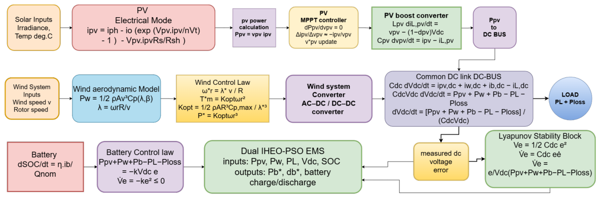
Therefore, the proposed EMS ensures continuous load supply, protects the battery operating limits and regulates the DC-link voltage [52]. The equation flow block diagram is illustrated in Figure 2.

3. Proposed Hybrid IHEO–PSO Energy Management Framework

3.1. Motivation and Overview

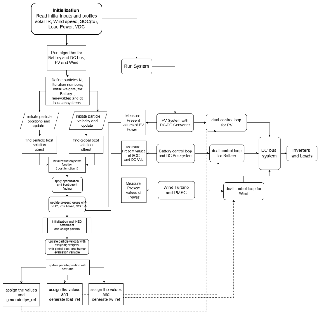
High renewable penetration introduces intermittency, converter-driven dynamics, and scheduling uncertainty, which can degrade power quality and increase losses when energy management is not optimally coordinated. To address this, this work proposes a hybrid metaheuristic energy management and scheduling framework (shown in Figure 3) that combines Improved Human Evolution Optimisation (IHEO) with particle swarm optimisation (PSO). In this hybridisation, IHEO provides strong global exploration and diversity preservation to avoid premature convergence, while PSO accelerates local exploitation and improves convergence speed near optimal operating points. The resulting Dual IHEO–PSO coordinator computes optimal dispatch and converter references over a scheduling horizon under operational constraints [53,54].

3.2. Scheduling and Energy Management Formulation

A discrete-time horizon-based scheduling problem is defined over k = 1 , , N with sampling interval Δ t . The decision vector at time k is [55,56]:
u ( k ) = P p v ( k ) , P w ( k ) , P b ( k ) , r ( k ) ,
where P p v and P w are renewable injections (subject to availability), P b is the battery charge/discharge power, and r ( k ) denotes additional power demand at step “k” [57] (e.g., curtailment, reserve margins, converter set points).
The multi-objective scheduling is expressed as a weighted cost:
min { u ( k ) } k = 1 N J cost = k = 1 N w 1 Φ P ( k ) + w 2 Φ V ( k ) + w 3 Φ SOC ( k ) + w 4 P loss ( k ) + w 5 Φ PQ ( k ) ,
Here, J cost represents the total optimisation cost minimised by IHEO, PSO, Dual IHEO–PSO, and WOA. The variable u ( k ) denotes the control decision at the sampling instant k, while N represents the total optimisation horizon. The coefficients w 1 , w 2 , and w 3 are the weighting factors assigned to the individual objective components. Φ P ( k ) represents the power mismatch, Φ V ( k ) denotes the DC-link voltage deviation, and Φ SOC ( k ) represents the battery state-of-charge deviation. The term P loss ( k ) represents the system power loss at sampling instant k, while Φ PQ ( k ) represents the power-quality deviation considered within the overall optimisation objective.

Power Balance and Operating Constraints

The microgrid power balance (DC-bus or equivalent) is enforced at each step [58]:
P p v ( k ) + P w ( k ) + P b ( k ) = P L ( k ) + P a u x ( k ) + P l o s s ( k ) ,
with renewable availability and curtailment:
0 P p v ( k ) P ¯ p v ( k ) , 0 P w ( k ) P ¯ w ( k ) ,
and battery power bounds:
P ¯ b , c h P b ( k ) P ¯ b , d i s .
Battery SOC dynamics (with efficiency) are modelled as:
SOC ( k + 1 ) = SOC ( k ) η b Δ t E n o m P b ( k ) ,
subject to:
SOC m i n SOC ( k ) SOC m a x .
If DC-link regulation is included explicitly, a compact constraint can be added:
V d c , m i n V d c ( k ) V d c , m a x ,
where V d c ( k ) is obtained from the converter/DC-link model or measured feedback [53,59].

3.3. Hybrid IHEO–PSO Solution Strategy

Let x denote a candidate schedule/dispatch trajectory (stacked u ( k ) for k = 1 , , N ). The hybrid optimiser iteratively updates x to reduce J while satisfying constraints. The framework follows two coordinated phases:
  • IHEO global search: generates diversified candidate solutions and explores the feasible region to avoid local minima, improving robustness under renewable uncertainty [9].
  • PSO local refinement: starting from elite IHEO candidates, PSO refines solutions for faster convergence and improved precision near the optimum [9].
A generic hybrid update can be expressed as [60]:
x ( t + 1 ) = R U P S O U I H E O ( x ( t ) ) ,
where U I H E O ( · ) denotes an IHEO evolution operator, U P S O ( · ) denotes PSO-based refinement, and R ( · ) repairs/projection handles constraint satisfaction (e.g., clipping, penalty, or feasibility restoration) [1,9].

Dual IHEO–PSO Update Mechanism and Constraint Handling

The proposed algorithm framework contains both IHEO (global search capability) and PSO (local refinement). The IHEO explore the feasible search space and returns the best candidate solution, X IHEO * , which is then transferred to the PSO stage as the initial global-best solution:
g best 0 = X IHEO * .
The velocity and position related to PSO is updated as,
v i k + 1 = ω v i k + c 1 r 1 p i b e s t x i k + c 2 r 2 g b e s t x i k ,
x i k + 1 = x i k + v i k + 1 ,
where x i k is the position and v i k is the velocity of particle i at iteration k, respectively, p i b e s t is the personal-best solution, g b e s t is the global-best solution, ω is the inertia weight, c 1 and c 2 are the acceleration coefficients, and r 1 , r 2 [ 0 , 1 ] are uniformly distributed random numbers.
To make sure that the candidates stays within the feasible boundary operating region, boundary repair technique implemented after every update,
x i , j k + 1 = min x j max , max x j min , x i , j k + 1 ,
subject to the main HPP operating constraints
S O C min S O C ( k ) S O C max ,
P BESS min P BESS ( k ) P BESS max ,
and
P PV ( k ) + P WT ( k ) + P BESS ( k ) = P load ( k ) .
Any value violation related to the candidate solution is projected back to the nearest feasible limit before fitness evaluation. The optimisation proceeds until the convergence criteria are satisfied.

4. Simulation Results and Comparative Analysis

4.1. Overview

A comparative study of the Whale Optimisation Algorithm (WOA) and Dual IHEO–PSO in response to hybrid energy management systems showed that there was a substantial performance disparity between them in terms of convergence, stability and quality of optimisation. Being a nature-inspired metaheuristic, WOA has decent global search potential but with low convergence rates, an oscillatory nature, and inefficiency in exploiting it under dynamic operating conditions. By contrast, the Dual IHEO–PSO algorithm establishes better human evolutionary optimisation with particle swarm intelligence that allows for a better exploration–exploitation balance and adaptive movement of decisions. Dual IHEO–PSO, as seen, delivers a low objective cost, faster convergence, and fewer oscillations, providing a stable DC bus voltage and controlled SOC variation. It has better retention of energy and lower prices than WOA, quantitatively, and better robustness and reliability, qualitatively. The hybrid form enables real-time responsiveness to changes in loads as well as generation to reduce the stress on a system and enhance power quality. Thus, Dual IHEO–PSO becomes a more sophisticated, efficient and scalable solution to next-generation smart hybrid energy management systems. A 24 h horizon was used for the energy-management analysis, while a 170 s horizon was used for short-term dynamic responses, including DC-link voltage and battery-current evaluation. Table 1 shows the initial operating conditions of the system, with a PV of 500 kW and a load of 420 kW, which leaves 80 kW unutilised to charge a battery. The starting value of SOC was 60, a safe operating range, which means that the energy could be stored efficiently without the danger of being overcharged or becoming deeply discharged. Moreover, the DC bus voltage was a little lower than the nominal voltage (780 V vs. 800 V), which contributed to the controlled charging activity and sufficient energy control under optimal control. The parameters setting is mentioned in Table 2.

4.2. Performance Analysis of the Proposed Dual IHEO–PSO EMS

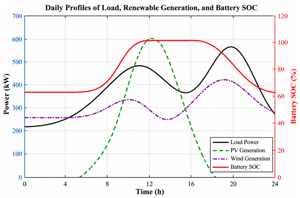
The reaction of the battery state of charge (SOC) learned through the Dual IHEO–PSO algorithm had highly efficient and advanced energy management behaviour with both industrial and commercial load scenarios. The SOC profile depicted a regulated and consistent change over the 24 h period and no abrupt change was observed, which was an indication of a steady system operating. The SOC became smaller at the start of the load demand and thereafter, there was a recovery toward the equilibrium, and it pointed toward intelligent scheduling of energy and a maximisation of available resources. The charge/discharge time curve in Figure 4 shows that the algorithm is operating effectively in managing the power flow but without subjecting the battery to any sudden strain.
Moreover, the SOC was not overcharged or over-deep discharged, which implied that there was no threat of overcharging or deep discharge. Such a controlled operation could be quite essential when it comes to battery life preservation, and it can go a long way to stretch the battery life. The global exploration property and the fast convergence property of Dual IHEO–PSO are hybrid in the sense that they are optimised more than conventional techniques that are rule-based or coefficient-based techniques. It ensures that there is maximum decision-making in a dynamic environment, which results in good energy distribution, and the loss is greatly reduced.
Further, the algorithm is dynamic and smart in that it reacts sufficiently to changes in loads and generation over the day. This helps produce a more reliable and robust system that is a major attribute of high-energy management systems. Overall, the Dual IHEO–PSO algorithm shows the best optimisation performance, which ensures steady operation, improved battery health and safe energy management with no danger of overcharge or over-discharge and, therefore, a highly viable solution to next-generation smart energy systems.
The absence of oscillations or highs and lows is a reflection of the steady and robust control capabilities of the Dual IHEO–PSO solution. In a highly developed energy management system (EMS) the demand should be controlled smoothly since the sources of power and storage elements can be put under minimum pressure. Our algorithm is intelligent in distributing energy based on the increasing load demand and at the same time maintaining system stability, and here, its high level of optimisation was observed.
Hourly load, PV and wind generation, and battery SOC mentioned in Table 3 is a simplified energy profile of the system over 24 h.At the start, both PV generation and load are low, while the battery has 60 percent SOC. By 5 h, PV and wind generation exceed the load, allowing the battery to charge to 100 percent, which it maintains through 8 to 10 h despite high load and generation levels. These data highlight how renewable generation and battery storage work together to balance supply and demand throughout the day.
Overall, this response demonstrates that the Dual IHEO–PSO algorithm is successful in smooth, constant, and optimal load power control and justifies its use in advanced smart energy systems. It assists in the good functionality and performance of the system, and it is a complement of the strategy of battery management which efficiently balances energy consumption.
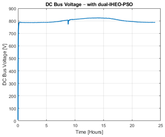
The system has a very stable and highly controlled system performance as shown in Figure 5 with the DC bus voltage response of the Dual IHEO–PSO algorithm, which is a very significant consideration in highly developed energy management systems. The voltage is rapidly raised at the beginning to its nominal operating level (about 790–800 V), which makes it a fast dynamic response and fine control action. Following this short period, the DC bus voltage does not change much over the 24 h but experiences slight variations that are damped.
A slight perturbation that can be seen in the mid-time interval is soon countered, and the voltage gets back to its steady-state value without oscillations. This is indicative of the robustness and rejection of disturbance abilities of the Dual IHEO–PSO algorithm. The absence of sustained overshoot, instability, and undershoot of the controller is a confirmation that the controller tightly controls its voltage under varying load and generation conditions.
A DC-bus constant voltage is a requisite to make power electronic converters and grid-connected systems stable. The smooth and regulated voltage profile offers efficient transfer of power, reduced stress on system components as well as improved system reliability. The Dual IHEO–PSO method is associated with greater voltage stability in comparison to conventional control or optimisation algorithms due to the hybrid optimisation mechanism, which can provide both speed of convergence and global search.
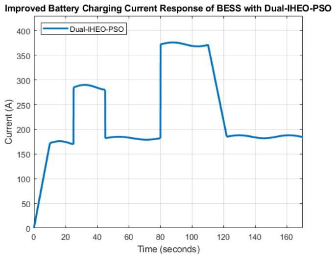
The Dual-IHEO–PSO current response exhibits a smooth start with well-controlled step transitions, a sign of fine control of battery charging levels. The resulted waveform is shown in Figure 6.
A small ripple and no instability characterise high-current regions, which have good damping and adaptive optimisation potential. In general, the response is steady, effective, and devoid of oscillations, which proves our method has better energy management and puts less load on the battery than using traditional techniques.

4.3. Comparative Analysis with Whale Optimisation Algorithm

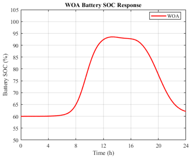
The relative SOC response in Figure 6 convincingly shows the optimal behaviour of the Dual IHEO–PSO algorithm when compared with conventional WOA. The tendency of all approaches is a decline in the specified SOC profile due to the load demand, yet the key difference is the fact that the rate of discharge behaviour is smoother and can be regulated [61]. Figure 7 shows the SOC waveform with the given PV and wind renewable sources with WOA. The graph shows a slower transition, and even with the peak PV waveform, it shows a slightly discharging state, indicating less effective utilisation of renewable surplus power.
The WOA approach, which is more effective than the rule-based and coefficient approaches, has a comparatively higher SOC depletion and lower adaptive control in the dynamic conditions. Similarly FB-RB (rule-based) is the least desirable option as it has a higher rate of discharges and is less intelligent since it operates using predetermined logic as compared to real-time optimisation. FB-COEFF is a fairly good technique but lacks the flexibility required in cases of variable loads and generation. The SOC comparison values of proposed and conventional algorithm is stated in Table 4.
The Dual IHEO–PSO algorithm, however, demonstrates the most rationalised and controlled SOC pathway, which ensures a more balanced and gradual discharge pattern. Dual IHEO–PSO uses both reinforcement of global exploration (IHEO) with explosive convergence (PSO) in contrast to WOA, which relies primarily on a metaheuristic search, thereby resulting in enhanced adaptive and accurate decision-making. It leads to better energy scheduling, less wasteful battery operation and enhanced maintenance of the SOC levels with time. System-wise, Dual IHEO–PSO is a guarantee of minimum stress on the battery, easy operation, and the absence of any chances of over-discharge, which in turn leads to increased battery life. In addition, it is highly applicable in high-energy management systems due to its stability when it comes to dynamism.
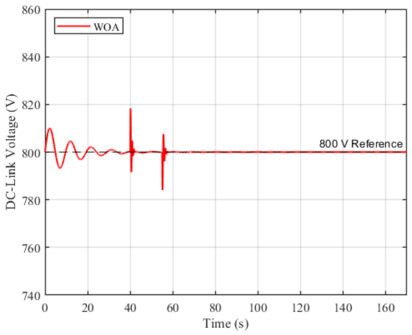
The voltage response obtained with WOA (Whale Optimisation Algorithm), depicted in Figure 8, contains visible oscillations, transient deviations and irregularities in the operating conditions that are dynamic in nature. The voltage of the first time interval vibrates about the nominal value, which implies that the damping capacity is insignificant and the convergence is slow. With the development of the system, there is a large amplitude oscillatory behaviour (particularly in the mid-region) with the spikes and dips in voltages showing up distinctly. These oscillations can be attributed to the inability to control the fast changes in load or in the system under WOA-based control, which leads to the low voltage regulation and increased load on the system. Weak disturbance rejection and less precision in control is also indicated by the existence of undershoot and overshoot. The qualitative SOC comparison is stated in Table 5.
The Dual IHEO-PSO voltage response has, in contrast, a superior dynamic response and stability that is needed in high-level energy management systems. Compared with WOA, the Dual IHEO-PSO approach can provide an easy-to-control voltage profile with few oscillations and a short settling time. Its hybrid nature, featuring the enhanced global exploration (IHEO) aspect coupled with speedy convergence and local optimisation (PSO), can be ingenious enough to respond to interference within the system and maintain the DC bus voltage at its set-point value.
Constant voltage regulation is directly proportional to quality power, reduced stress on converters and loads, and reliability of the system. The Dual IHEO–PSO method proves effective in eliminating high-voltage distortion and reducing the probability of instability, overvoltage, or undervoltage. Moreover, its ability to minimise oscillations and rapid recovery after disruptions is an indication of its robustness and the ability to work in various circumstances.
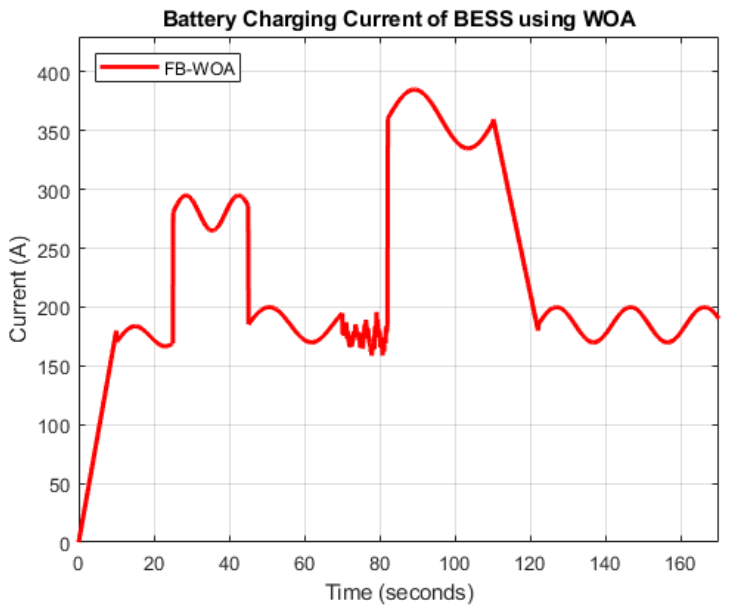
The power response obtained with WOA shown in Figure 9 reflects noticeable variations at the operating range and repeating positive and negative spikes at the nominal operating range. Although the average power can be maintained at the desired value by the method, the response is not sufficiently smooth, and oscillations are often present, indicating that accuracy is not very high even after optimisation when used in dynamic conditions. In particular, the elevated transient peaks of the onset and near the end of the interval signify a weaker damping and a decreased control robustness. Such variations are potential contributors to unnecessary load on converters, storage components and loads that are attached to converters and therefore the overall quality of power management [61]. Brief comparison between proposed Dual IHEO-PSO and WOA is discussed in Table 6.
Contrastingly, the Dual IHEO–PSO power response may be regarded as evidently superior since it has smoother, more stable and more optimised behaviour. Our research indicates that due to the combination of IHEO and PSO, there is better convergence and effective real-time decision-making since the evolutionary optimisation method has good exploration ability, and the particle swarm optimisation allows quick and precise exploitation. The current response illustrated in Figure 10, based on WOA, shows some observable oscillations and irregular variations particularly in the mid-region, which means lower damping and control accuracy. The quantitative and qualitative load power consumption comparison is stated in Table 7.
Large current peaks are characterised by instability and aggressive behaviour, which is characteristic of poor response to dynamic variations. In general, the response is less stable and smoother, resulting in higher battery stress and lower energy management efficiency than Dual IHEO–PSO. It is clear from the comparison in Table 8, that Dual IHEO–PSO has a much better BESS charging current response than WOA. Despite the fact that both approaches give similar current levels, the oscillations, ripple, and irregularities in WOA are more evident in dynamic areas, which implies lower control precision. However, the current profile of Dual IHEO–PSO is smooth and controlled with a small amount of variation and more rapid settling following disturbances. This translates into lower levels of battery stresses, higher charging stability, and energy efficiency. On the whole, Dual IHEO–PSO has a hybrid optimisation potential that guarantees high robustness, efficiency, and reliability, making it more applicable in advanced hybrid energy management systems. BESS charging current comparison is stated in Table 8.

4.4. Convergence Performance Analysis

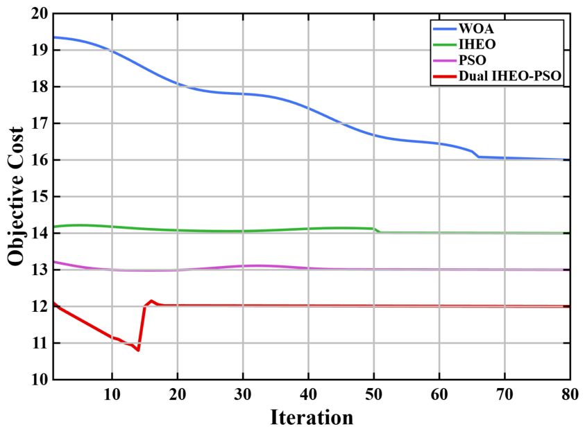
Dual IHEO–PSO starts with a lower initial objective cost and reaches a lower final cost than WOA, indicating higher solution quality. It converges much faster and stabilises early, unlike WOA, which fluctuates for longer iterations. The very low oscillations in Dual IHEO–PSO highlight its superior stability and smooth optimisation performance. The multiobjective function utilised in Equation (44) with individual terms representing power loss, power quality deviation, battery SOC deviation and DC-link deviation remains the key objective of the proposed algorithm. Comparison of objective function and convergence performance is stated in Table 9.
Dual IHEO–PSO consistently achieves the lowest objective cost, outperforming WOA, IHEO, and PSO. WOA converges slowly with higher oscillations, IHEO is stable but at a higher cost, and PSO is moderately fast but not as optimal. Overall, the red line clearly highlights Dual IHEO–PSO as the superior algorithm.
As is evident in the comparison, Dual IHEO–PSO is much better in all essential performance areas of the hybrid energy management when compared with WOA. It has lower initial and final objective costs, as illustrated in Figure 10, meaning a high-quality solution at the beginning and at convergence. Additionally, its accelerated convergence rate and earlier solution at the settling iteration point to high optimisation efficiency. Dual IHEO–PSO has stable, smooth and reliable performance with few oscillations, as compared to WOA, which has the disadvantages of higher oscillations and medium stability. This ameliorated performance can be attributed to its hybrid nature, which is characterised by excellent global exploration and effective local exploitation. Overall, Dual IHEO–PSO is more efficient in search, more stable in the system, and more efficient in energy management, making it a more developed and practical solution for real-world application. Table 10 summarises the statistical performance of the algorithms over 10 independent runs using the best, mean, median, standard deviation, interquartile range (IQR), and average computational time. The Dual IHEO–PSO achieves the lowest values, validating the authenticity of the proposed approach.

4.5. Overall Discussion

The overall performance comparison of the proposed Dual IHEO–PSO (Improved Human Evolutionary Optimisation–Particle Swarm Optimisation) algorithm with respect to the SOC, voltage and power responses clearly indicates that the algorithm is superior to conventional ones such as WOA. The results confirm that Dual IHEO–PSO presents a highly streamlined, stable and intelligent power management system, which would be suitable for the new generation and sophisticated power systems.
According to the SOC analysis, the specified strategy guarantees a managed and unproblematic charge–discharge curve and keep the battery within a reasonable operating range, which will be effective in preventing instances of overcharge and deep discharge. This directly influences the need to grow battery life, reduce degradation and create minimal stress of operation, which is necessary in present-day energy storage systems. Otherwise, comparatively, the rate of SOC depletion and adaptive control is higher in WOA and other traditional methods.
Dual IHEO–PSO has tight DC-bus voltage regulation, low oscillations, small settling time and large disturbance rejection. The approach proposed enables the maintenance of a nearly constant voltage profile, in contrast to WOA, which presents noticeable voltage fluctuations and intermittent instability; this explains the high-quality power, stability of the system, and ensures the safety of power electronic devices.
Dual IHEO–PSO produced a lower final objective cost of approximately 12, compared with nearly 16 for WOA, indicating a higher-quality optimisation result. It also converged more rapidly, reaching a stable solution within about 18–20 iterations, whereas WOA required nearly 65 iterations to settle. Moreover, the proposed method exhibited a smoother convergence trend with fewer oscillations, together with improved battery SOC behaviour, which reflects more stable and reliable coordination of the PV, wind, and battery subsystems. The high performance of Dual IHEO–PSO can be attributed to its hybrid optimisation structure; IHEO and PSO possess a global exploration capacity and rapid convergence and accuracy, respectively, which enables the method to make decisions under uncertainty and dynamic circumstances even better. The result is better energy scheduling, enhanced robustness, and better efficiency of the system in general.


5. Conclusions

The waveform-based comparative analysis verified the superior performance of the proposed Dual IHEO–PSO algorithm over conventional WOA. The SOC variance showed the battery charging at start of the day, staying charged the whole day, and then discharging when there was not enough power from renewables, indicating a smoother charge–discharge profile and reduced battery stress. The DC-bus voltage response also confirmed enhanced regulation, where the maximum overshoot and undershoot were reduced by 68% and 74%, respectively, and the voltage deviation range decreased from about 35 V to 7 V. The settling time was further improved from nearly 80 s to 10–15 s, demonstrating faster transient recovery and stronger disturbance rejection.
Similarly, the power response showed a more stable profile, with the fluctuation range reduced from approximately 55 kW to 15 kW, the average power deviation improved from ±5–7 kW to ±1–2 kW, and the negative power peak reduced from about 20 kW to 5 kW. The BESS charging current ripple was also reduced from ±15 A to ±3 A, confirming smoother and safer battery charging operation. Furthermore, the convergence response showed that the objective cost decreased from approximately 16.0 with WOA to 12.03 with Dual IHEO–PSO, while the settling iteration improved around 18–20 iterations. These results confirm that the hybrid Dual IHEO–PSO structure improves SOC retention, voltage stability, power quality, current smoothness, convergence speed, and overall objective cost performance, making it a reliable optimisation strategy for advanced energy storage and modern power management systems. The proposed hybrid algorithm was validated through simulations under specific operating conditions and constraints. The present study did not consider factors such as battery degradation, forecasting uncertainty, communication delays, converter nonlinearities, or probabilistic reliability indices. Future work will therefore focus on real-time implementation of the proposed algorithm, including battery-aging models, communication effects, forecasting uncertainty, and comprehensive reliability assessment using recognised indices such as LPSP, LOLP, or EENS.

Author Contributions

M.Z.T. and A.A. for conceptualisation and methodology, M.Z.T. and A.A. for data analysis and implementation, M.Z.T., A.A. and B.K.D. for formal analysis, writing, editing and review. A.A. and B.K.D. for supervision and project administration. All authors have read and agreed to the published version of the manuscript.

Funding

This research received no external funding.

Data Availability Statement

The data supporting the findings of this study are not publicly available due to privacy considerations and ongoing research.

Conflicts of Interest

The authors declare no conflicts of interest.

Abbreviations

The following abbreviations are used in this manuscript:
HPPHybrid Power Plant
EMSEnergy Management System
PVPhotovoltaic
BESSBattery Energy Storage System
SOCState of Charge
PMSGPermanent-Magnet Synchronous Generator
MPPTMaximum Power Point Tracking
P&OPerturb and Observe
IHEOImproved Human Evolutionary Optimisation
PSOParticle Swarm Optimisation
WOAWhale Optimisation Algorithm
DCDirect Current
WECSWind Energy Conversion System
DC–DCDirect-Current-to-Direct-Current Converter
RLCResistor–Inductor–Capacitor
ACAlternating Current
MPPMaximum Power Point
PIProportional–Integral Controller
ECMEquivalent Circuit Model
RESRenewable Energy Sources
PCCPoint of Common Coupling

References

  1. Agajie, T.F.; Ali, A.; Fopah-Lele, A.; Amoussou, I.; Khan, B.; Velasco, C.L.R.; Tanyi, E. A comprehensive review on techno-economic analysis and optimal sizing of hybrid renewable energy sources with energy storage systems. Energies 2023, 16, 642. [Google Scholar] [CrossRef] [Scilit]
  2. Das, K.; Hansen, A.D.; Leon, J.P.M.; Zhu, R.; Gupta, M.; Pérez-Rúa, J.-A.; Long, Q.; Pombo, D.V.; Barlas, A.; Gocmen, T.; et al. Research Challenges and Opportunities of Utility-Scale Hybrid Power Plants. Wiley Interdiscip. Rev. Energy Environ. 2025, 14, e70001. [Google Scholar] [CrossRef] [Scilit]
  3. Tariq, M.Z.; Rahman, S.; Khan, I.A.; Khan, F.N. PV Fed Battery and Ultra-Capacitor Based Hybrid Energy Storage for Powering Marine Loads. In Proceedings of the 2021 International Conference on Digital Futures and Transformative Technologies (ICoDT2), Islamabad, Pakistan, 20–21 May 2021; pp. 1–6. [Google Scholar]
  4. Sahri, Y.; Belkhier, Y.; Tamalouzt, S.; Ullah, N.; Shaw, R.N.; Chowdhury, M.S.; Techato, K. Energy management system for hybrid PV/wind/battery/fuel cell in microgrid-based hydrogen and economical hybrid battery/super capacitor energy storage. Energies 2021, 14, 5722. [Google Scholar] [CrossRef] [Scilit]
  5. Li, W.; Jin, R.; Ma, X.; Zhang, G. Capacity Optimal Allocation Method and Frequency Division Energy Management for Hybrid Energy Storage System Considering Grid-Connected Requirements in Photovoltaic System. Energies 2023, 16, 4154. [Google Scholar] [CrossRef] [Scilit]
  6. Hosseini, E.; Horrillo-Quintero, P.; Carrasco-Gonzalez, D.; García-Triviño, P.; Sarrias-Mena, R.; García-Vázquez, C.A.; Fernández-Ramírez, L.M. Optimal energy management system for grid-connected hybrid power plant and battery integrated into multilevel configuration. Energy 2024, 294, 130765. [Google Scholar] [CrossRef] [Scilit]
  7. Suresh, B.; Lakshmiprabha, K.E.; Kumar, U.A.; Natraj, N.A. Battery integration and grid-connected hybrid power plant with an optimal energy management system integrated into a multilevel configuration. J. Energy Storage 2025, 121, 116514. [Google Scholar] [CrossRef] [Scilit]
  8. Abdelghany, M.B.; Al-Durra, A.; Gao, F. A coordinated optimal operation of a grid-connected wind-solar microgrid incorporating hybrid energy storage management systems. IEEE Trans. Sustain. Energy 2023, 15, 39–51. [Google Scholar] [CrossRef] [Scilit]
  9. Das, K.; Cossu, A.; Sørensen, P.E.; Leon, J.P.M. Component sizing of an utility-scale hybrid power plant. In Proceedings of the 6th International Hybrid Power Systems Workshop, Madeira, Portugal, 26–27 April 2022. [Google Scholar]
  10. Pan, T.; Wang, Z.; Tao, J.; Zhang, H. Operating strategy for grid-connected solar-wind-battery hybrid systems using improved grey wolf optimization. Electr. Power Syst. Res. 2023, 220, 109346. [Google Scholar] [CrossRef] [Scilit]
  11. Maghfiroh, H.; Wahyunggoro, O.; Cahyadi, A.I. Energy management in hybrid electric and hybrid energy storage system vehicles: A fuzzy logic controller review. IEEE Access 2024, 12, 56097–56109. [Google Scholar] [CrossRef] [Scilit]
  12. Pengtem, C.; Deeum, S.; Amirullah; Ohgaki, H.; Romphochai, S.; Bhumkittipich, P.; Bhumkittipich, K. Design of Multi-Objective Energy Management for Remote Communities Connected with an Optimal Hybrid Integrated Photovoltaic–Hydropower–Battery Energy Storage System (PV-HP-BESS) Using Improved Particle Swarm Optimization. Energies 2025, 18, 2250. [Google Scholar] [CrossRef] [Scilit]
  13. Mahapatra, B.; Nayyar, A. Home energy management system (HEMS): Concept, architecture, infrastructure, challenges and energy management schemes. Energy Syst. 2022, 13, 643–669. [Google Scholar] [CrossRef] [Scilit]
  14. Ahmed, F.; Al-Abri, R.; Yousef, H.; Massoud, A.M. An optimal energy dispatch management system for hybrid power plants: PV-grid-battery-diesel generator-pumped hydro storage. IEEE Access 2024, 12, 143307–143326. [Google Scholar] [CrossRef] [Scilit]
  15. Safavi, V.; Vaniar, A.M.; Bazmohammadi, N.; Vasquez, J.C.; Keysan, O.; Guerrero, J.M. A battery degradation-aware energy management system for agricultural microgrids. J. Energy Storage 2025, 108, 115059. [Google Scholar] [CrossRef] [Scilit]
  16. Zhu, R.; Das, K.; Sørensen, P.E.; Hansen, A.D. A Review on Energy Management System for Grid-Connected Utility-Scale Renewable Hybrid Power Plants. Wiley Interdiscip. Rev. Energy Environ. 2025, 14, e70004. [Google Scholar] [CrossRef] [Scilit] [PubMed]
  17. Guo, C.; Wang, X.; Zheng, Y.; Zhang, F. Real-time optimal energy management of microgrid with uncertainties based on deep reinforcement learning. Energy 2022, 238, 121873. [Google Scholar] [CrossRef] [Scilit]
  18. Saleem, M.I.; Saha, S.; Izhar, U.; Ang, L. Optimized energy management of a solar battery microgrid: An economic approach towards voltage stability. J. Energy Storage 2024, 90, 111876. [Google Scholar] [CrossRef] [Scilit]
  19. Nazaralizadeh, S.; Banerjee, P.; Srivastava, A.K.; Famouri, P. Battery energy storage systems: A review of energy management systems and health metrics. Energies 2024, 17, 1250. [Google Scholar] [CrossRef] [Scilit]
  20. Kechida, A.; Gozim, D.; Toual, B.; Alharthi, M.M.; Agajie, T.F.; Ghoneim, S.M.S.; Ghaly, R.N.R. Smart control and management for a renewable energy based stand-alone hybrid system. Sci. Rep. 2024, 14, 32039. [Google Scholar] [CrossRef] [Scilit] [PubMed]
  21. El Boujdaini, L.; Mezrhab, A.; Moussaoui, M.A.; Jurado, F.; Vera, D. Sizing of a stand-alone PV–wind–battery–diesel hybrid energy system and optimal combination using a particle swarm optimization algorithm. Electr. Eng. 2022, 104, 3339–3359. [Google Scholar] [CrossRef] [Scilit]
  22. Mquqwana, M.A.; Krishnamurthy, S. Particle swarm optimization for an optimal hybrid renewable energy microgrid system under uncertainty. Energies 2024, 17, 422. [Google Scholar] [CrossRef] [Scilit]
  23. Rashad, M.; Abdellatif, M.S.; Rabie, A.H. An improved human evolutionary optimization algorithm for maximizing green hydrogen generation in intelligent energy management system (IEMS). Results Eng. 2025, 27, 105998. [Google Scholar] [CrossRef] [Scilit]
  24. Bhavana, K.; Lalitha, K.; Revana, G.; Amaleswari, R. An Improved Human Evolutionary Optimization Algorithm for Optimal Integration of Hybrid Fast Charging Stations. Int. J. Intell. Eng. Syst. 2025, 18, 813. [Google Scholar] [CrossRef] [Scilit]
  25. Niccolai, A.; Trimarchi, S.; Barbazza, L.F.; Gandelli, A.; Zich, R.; Grimaccia, F.; Leva, S. Effective Customization of Evolutionary Algorithm-Based Energy Management System Optimization for Improved Battery Management in Microgrids. Energies 2025, 18, 2384. [Google Scholar] [CrossRef] [Scilit]
  26. Kapen, P.T. Multi-objective optimization of a Wind/Photovoltaic/Battery hybrid system using a novel hybrid meta-heuristic algorithm. Energy Convers. Manag. 2025, 327, 119533. [Google Scholar] [CrossRef] [Scilit]
  27. Bilal, M.; Bokoro, P.N.; Sharma, G. Hybrid optimization for sustainable design and sizing of standalone microgrids integrating renewable energy, diesel generators, and battery storage with environmental considerations. Results Eng. 2025, 25, 103764. [Google Scholar] [CrossRef] [Scilit]
  28. Hu, J.; Song, Z.; Tan, Y.; Tan, M. Optimizing integrated energy systems using a hybrid approach blending grey wolf optimization with local search heuristics. J. Energy Storage 2024, 87, 111384. [Google Scholar] [CrossRef] [Scilit]
  29. Liu, X.; Zhao, T.; Deng, H.; Wang, P.; Liu, J.; Blaabjerg, F. Microgrid energy management with energy storage systems: A review. CSEE J. Power Energy Syst. 2022, 9, 483–504. [Google Scholar] [CrossRef] [Scilit]
  30. Montilla-DJesus, M.; Franco-Mejía, É.; Trujillo, E.R.; Rodriguez-Amenedo, J.L.; Arnaltes, S. Coordinated control system between grid–VSC and a DC microgrid with hybrid energy storage system. Electronics 2021, 10, 2699. [Google Scholar] [CrossRef] [Scilit]
  31. Sánchez, H.A.; Ortega, R.; Carranza, O.; Rodríguez, J.J.; García, V.H.; Ortega, L.M.; Memije, D. Controller Design for Autonomous Direct Current Microgrid Operation. Electronics 2024, 13, 2943. [Google Scholar] [CrossRef] [Scilit]
  32. De Soto, W.; Klein, S.A.; Beckman, W.A. Improvement and validation of a model for photovoltaic array performance. Sol. Energy 2006, 80, 78–88. [Google Scholar] [CrossRef] [Scilit]
  33. Villalva, M.G.; Gazoli, J.R.; Ruppert Filho, E. Comprehensive approach to modeling and simulation of photovoltaic arrays. IEEE Trans. Power Electron. 2009, 24, 1198–1208. [Google Scholar] [CrossRef] [Scilit]
  34. Ridha, H.M.; Hizam, H.; Mirjalili, S.; Othman, M.L.; Ya’acob, M.E.; Ahmadipour, M. Parameter extraction of single, double, and three diodes photovoltaic model based on guaranteed convergence arithmetic optimization algorithm and modified third order Newton Raphson methods. Renew. Sustain. Energy Rev. 2022, 162, 112436. [Google Scholar] [CrossRef] [Scilit]
  35. Han, Y.; Lin, X.; Yang, P.; Xu, L.; Xu, Y.; Blaabjerg, F. Structure-preservation model aggregation for two-stage inverters based large-scale photovoltaic system. IEEE Access 2019, 8, 1824–1839. [Google Scholar] [CrossRef] [Scilit]
  36. Ramos-Paja, C.A.; Danilo-Montoya, O.; Grisales-Noreña, L.F. Photovoltaic System for Microinverter Applications Based on a Non-Electrolytic-Capacitor Boost Converter and a Sliding-Mode Controller. Electronics 2022, 11, 2923. [Google Scholar] [CrossRef] [Scilit]
  37. Kahani, R.; Jamil, M.; Iqbal, M.T. Direct model reference adaptive control of a boost converter for voltage regulation in microgrids. Energies 2022, 15, 5080. [Google Scholar] [CrossRef] [Scilit]
  38. Sun, C.; Ling, J.; Wang, J. Research on a novel and improved incremental conductance method. Sci. Rep. 2022, 12, 15700. [Google Scholar] [CrossRef] [Scilit] [PubMed]
  39. Badawi, A.; Elzein, I.M.; Matter, K.; El-bayeh, C.Z.; Ali, H.; Zyoud, A. A State-of-the-Art Comprehensive Review on Maximum Power Tracking Algorithms for Photovoltaic Systems and New Technology of the Photovoltaic Applications. Energies 2025, 18, 6555. [Google Scholar] [CrossRef] [Scilit]
  40. Hussein, K.H.; Muta, I.; Hoshino, T.; Osakada, M. Maximum photovoltaic power tracking: An algorithm for rapidly changing atmospheric conditions. IEE Proc.-Gener. Transm. Distrib. 1995, 142, 59–64. [Google Scholar] [CrossRef] [Scilit]
  41. Esram, T.; Chapman, P.L. Comparison of photovoltaic array maximum power point tracking techniques. IEEE Trans. Energy Convers. 2007, 22, 439–449. [Google Scholar] [CrossRef] [Scilit]
  42. Castillo, O.C.; Andrade, V.R.; Rivas, J.J.R.; González, R.O. Comparison of power coefficients in wind turbines considering the tip speed ratio and blade pitch angle. Energies 2023, 16, 2774. [Google Scholar] [CrossRef] [Scilit]
  43. Brandetti, L.; Mulders, S.P.; Liu, Y.; Watson, S.; van Wingerden, J.-W. Analysis and multi-objective optimisation of wind turbine torque control strategies. Wind. Energy Sci. 2023, 8, 1553–1573. [Google Scholar] [CrossRef] [Scilit]
  44. Chhipą, A.A.; Chakrabarti, P.; Bolshev, V.; Chakrabarti, T.; Samarin, G.; Vasilyev, A.N.; Ghosh, S.; Kudryavtsev, A. Modeling and control strategy of wind energy conversion system with grid-connected doubly-fed induction generator. Energies 2022, 15, 6694. [Google Scholar] [CrossRef] [Scilit]
  45. He, H.; Xiong, R.; Fan, J. Evaluation of lithium-ion battery equivalent circuit models for state of charge estimation by an experimental approach. Energies 2011, 4, 582–598. [Google Scholar] [CrossRef] [Scilit]
  46. Plett, G.L. Battery Management Systems, Volume I: Battery Modeling; Artech House: Norwood, MA, USA, 2015. [Google Scholar]
  47. Hassan, M.U.; Saha, S.; Haque, M.E.; Islam, S.; Mahmud, A.; Mendis, N. A comprehensive review of battery state of charge estimation techniques. Sustain. Energy Technol. Assess. 2022, 54, 102801. [Google Scholar] [CrossRef] [Scilit]
  48. Wu, Z.Q.; Geng, S.C.; Xie, Z.K. Bus voltage stability control of DC microgrid considering voltage constraints. J. Ind. Manag. Optim. 2024, 20, 1203–1219. [Google Scholar] [CrossRef] [Scilit]
  49. Babaiahgari, B.; Jeong, Y.; Park, J.-D. Stability analysis for interconnected DC microgrids with constant power loads. In Proceedings of the 2019 IEEE Energy Conversion Congress and Exposition (ECCE), Baltimore, MD, USA, 29 September–3 October 2019; IEEE: New York, NY, USA, 2019; pp. 5778–5782. [Google Scholar]
  50. Montenegro-Oviedo, J.A.; Ramos-Paja, C.A.; Orozco-Gutierrez, M.L.; Franco-Mejía, E.; Serna-Garcés, S.I. Adaptive controller for bus voltage regulation on a DC microgrid using a SEPIC/Zeta battery charger/discharger. Mathematics 2023, 11, 793. [Google Scholar] [CrossRef] [Scilit]
  51. Nougain, V.; Panigrahi, B.K. Voltage Regulation of DC Microgrid by Robust Back-stepping Control Technique of Voltage Source Converter. In Proceedings of the 2018 20th National Power Systems Conference (NPSC), Tiruchirappalli, India, 14–16 December 2018; pp. 1–5. [Google Scholar]
  52. Ghosh, S.K.; Roy, T.K.; Pramanik, M.A.H.; Mahmud, M.A. A nonlinear double-integral sliding mode controller design for hybrid energy storage systems and solar photovoltaic units to enhance the power management in DC microgrids. IET Gener. Transm. Distrib. 2022, 16, 2228–2241. [Google Scholar] [CrossRef] [Scilit]
  53. Tightiz, L.; Yoo, J. A review on a data-driven microgrid management system integrating an active distribution network: Challenges, issues, and new trends. Energies 2022, 15, 8739. [Google Scholar] [CrossRef] [Scilit]
  54. Wang, X.; Xu, H. Multi-strategy enhanced Human Evolution Optimization Algorithm and its engineering applications. Ain Shams Eng. J. 2026, 17, 103818. [Google Scholar] [CrossRef] [Scilit]
  55. Dizqah, A.M.; Maheri, A.; Busawon, K.; Kamjoo, A. A multivariable optimal energy management strategy for standalone DC microgrids. IEEE Trans. Power Syst. 2014, 30, 2278–2287. [Google Scholar] [CrossRef] [Scilit]
  56. Morstyn, T.; Hredzak, B.; Aguilera, R.P.; Agelidis, V.G. Model predictive control for distributed microgrid battery energy storage systems. IEEE Trans. Control Syst. Technol. 2017, 26, 1107–1114. [Google Scholar] [CrossRef] [Scilit]
  57. Goh, H.H.; Shi, S.; Liang, X.; Zhang, D.; Dai, W.; Liu, H.; Wong, S.Y.; Kurniawan, T.A.; Goh, K.C.; Cham, C.L. Optimal energy scheduling of grid-connected microgrids with demand side response considering uncertainty. Appl. Energy 2022, 327, 120094. [Google Scholar] [CrossRef] [Scilit]
  58. Batiyah, S.; Sharma, R.; Abdelwahed, S.; Alhosaini, W.; Aldosari, O. Predictive control of PV/battery system under load and environmental uncertainty. Energies 2022, 15, 4100. [Google Scholar] [CrossRef] [Scilit]
  59. Quiñones, J.J.; Pineda, L.R.; Ostanek, J.; Castillo, L. Towards smart energy management for community microgrids: Leveraging deep learning in probabilistic forecasting of renewable energy sources. Energy Convers. Manag. 2023, 293, 117440. [Google Scholar] [CrossRef] [Scilit]
  60. Lian, J.; Hui, G. Human evolutionary optimization algorithm. Expert Syst. Appl. 2024, 241, 122638. [Google Scholar] [CrossRef] [Scilit]
  61. Siddiqui, N.A.; Tahir, H.; Akram, M.; Manzoor, H.U. Optimized Control of Hybrid Energy Storage Systems Using Whale Optimization Algorithm for Enhanced Battery Longevity and Stability in Microgrids. Eng. Rep. 2025, 7, e70199. [Google Scholar] [CrossRef] [Scilit]
Figure 1. Single line diagram of proposed model.
Energies 19 04429 g001
Figure 2. Equation based modelling flow diagram.
Energies 19 04429 g002
Figure 3. Working flow of Dual IHEO–PSO hybrid algorithm. (Dotted lines represents control signal).
Energies 19 04429 g003
Figure 4. Daily profiles of load demand, PV, wind, and battery SOC over a 24 h operating period
Energies 19 04429 g004
Figure 5. DC bus voltage of proposed algorithm.
Energies 19 04429 g005
Figure 6. BESS current response with Dual IHEO–PSO.
Energies 19 04429 g006
Figure 7. SOC response with WOA.
Energies 19 04429 g007
Figure 8. Bus voltage response with WOA.
Energies 19 04429 g008
Figure 9. BESS charging current using WOA.
Energies 19 04429 g009
Figure 10. Cost convergence of different algorithms.
Energies 19 04429 g010
Table 1. Implementation settings of the proposed IHEO–PSO algorithm.
ParameterSetting
IHEO population size15
PSO swarm size15
Maximum IHEO iterations80
Maximum PSO iterations80
PSO inertia weight, ω 0.7
Cognitive coefficient, c 1 1.8
Social coefficient, c 2 1.8
InitialisationWithin predefined bounds
IHEO–PSO information transferBest IHEO solution to PSO
Exchange frequencyOnce per optimisation cycle
Constraint handlingBoundary repair and feasibility check
Termination criterionMaximum iterations/convergence
Table 2. System initialisation parameters for sources and demand load.
ParameterSymbolValueUnitDescription
DC bus voltage V DC 780VInitial DC-link operating voltage
Available PV power P pv 500kWTotal available solar generation power
Load demand P load 420kWTotal system load requirement
Battery state of chargeSOC0.60p.u.Initial battery state of charge
PV power in kW P pv 500kWAvailable PV power in practical units
Load power in kW P load 420kWLoad demand in practical units
Power surplus P pv P load 80kWExcess PV power available for battery charging or storage
Power surplus in kW P pv P load 80kWNet positive generation margin
SOC percentage SOC × 100 60%Initial battery charge level
DC bus voltage error 800 V DC 20VDeviation from the nominal 800 V DC-link reference
Table 3. System operation profile over time.
Time [h]Load Power [kW]PV Generation [kW]Wind Generation [kW]Battery SOC [%]
0210021060
620510035065
12510600430100
1855050400100
24210012058
Table 4. Quantitative SOC comparison: WOA vs. Dual IHEO–PSO.
MetricWOADual IHEO–PSOComparison
Initial SOC (%)∼60∼60Same initial condition
Maximum SOC (%)∼94∼100 5 % higher
SOC Increase During Charging (%)∼34∼39Higher with Dual IHEO–PSO
Final SOC (%)∼63∼66 5 % higher
Peak-to-Final SOC Reduction (%)∼31∼33Comparable
SOC Ripple Around Peak (%) 0.6 0.2 67 % lower
Charging TransitionSlowerFasterImproved
SOC FluctuationsSmall–moderateVery lowReduced
Renewable Surplus UtilisationModerateHigherImproved
SOC RegulationStableMore stableImproved
Table 5. Qualitative SOC performance comparison.
AspectObservation with WOADual IHEO–PSO
Initial SOC ResponseStable initial operationStable and well-regulated operation
Charging TransitionRelatively slowFaster and smoother
Behaviour During High Renewable GenerationSmall fluctuations with limited charging responseMore effective charging and smoother SOC regulation
Mid-cycle BehaviourMinor SOC variationsMore balanced and controlled
Response to Load VariationsModerate response with larger SOC variationFaster and more coordinated response
End-of-Cycle SOCSlightly lowerHigher SOC maintained
SOC FluctuationsSmall to moderateVery low
Renewable Energy UtilizationModerateImproved utilization of renewable surplus
Battery Operating StressRelatively higher due to SOC variationsReduced due to smoother charge/discharge control
Table 6. Quantitative performance comparison of bus voltage response at an 800 V DC-link reference.
MetricWOADual IHEO–PSOImprovement
DC-Link Reference Voltage (V)800800Same operating point
Peak Overshoot Above Reference (V)∼25∼7 72 %
Peak Undershoot Below Reference (V)∼22∼7 68 %
Peak-to-Peak Voltage Deviation (V)∼47∼14 70 %
Settling Time (s)∼80∼10–15∼81– 88 %
Oscillation MagnitudeHighVery LowReduced
Steady-State Error (V)∼2–3 0.5 ∼75– 83 %
Disturbance RejectionModerateHighImproved
Voltage RegulationModerateHighImproved
Table 7. Quantitative and qualitative load power comparison. ↓ showing the “significant decrease” of oscillation.
MetricWOADual IHEO–PSOImprovement
Peak Positive Power (kW)∼35∼100−71%
Peak Negative Power (kW) 20 5 −75%
Power Fluctuation Range (kW)∼55∼15−72%
Average Power Deviation (kW) ± 5 –7 ± 1 –2−70%
Oscillation LevelHighVery lowSignificant ↓
StabilityModerateVery highImproved
Control PrecisionMediumHighImproved
Energy EfficiencyModerateHighImproved
Stress on ComponentsHighLowReduced
Power QualityFluctuatingSmooth and regulatedEnhanced
Table 8. BESS charging current performance comparison.
Performance MeasureWOADual IHEO–PSOComparative Remark
Initial current∼0 A∼0 ABoth methods start from approximately zero current.
First settling current level∼175 A∼173 ABoth methods show a similar initial current regulation level.
First peak charging current∼295 A∼290 AWOA gives a slightly higher peak and shows less controlled behaviour.
Second peak charging current∼385 A∼375 AWOA produces a higher peak with greater oscillation.
Final steady current∼185–200 A∼185–188 ADual IHEO–PSO maintains a more stable current in the final region.
Current fluctuation in steady region ± 15 A ± 3 ADual IHEO–PSO shows a considerably lower current ripple.
Mid-region oscillation levelHighVery lowDual IHEO–PSO provides better current stability.
Table 9. Comparison of objective cost and convergence performance.
MetricWOAIHEOPSODual IHEO–PSO
Initial Objective Cost 19.2 14.2 13.2 12.12
Final Objective Cost 16.0 14.0 13.0 12.03
Convergence BehaviourSlow, fluctuatingSlow, stableSlow, stableVery fast, with early stabilisation
OscillationsLowLowVery low
Settling Iteration 30 + ∼40–50∼30–40∼15–20
Table 10. Statistical performance comparison over 10 independent runs. Bold means to distinguish that this is the proposed algorithm and has best values over conventional algorithm comparison.
AlgorithmBestMeanMedianStd. Dev.IQRAvg. Time (s)
IHEO4.824244.835104.831370.009910.011840.000532
PSO4.824104.830864.827840.006740.006990.000570
Dual IHEO–PSO4.824004.824114.824080.000110.000190.000725
WOA4.826354.838234.838200.011790.012090.000782
Disclaimer/Publisher’s Note: The statements, opinions and data contained in all publications are solely those of the individual author(s) and contributor(s) and not of MDPI and/or the editor(s). MDPI and/or the editor(s) disclaim responsibility for any injury to people or property resulting from any ideas, methods, instructions or products referred to in the content.