Review

Insulation Monitoring Systems in Low-Voltage IT Networks—A Review

by
Arkadiusz Frącz
1,* and
Stanislaw Czapp
2
1
Faculty of Mechanical and Electrical Engineering, Polish Naval Academy, Śmidowicza 69, 81-127 Gdynia, Poland
2
Faculty of Electrical and Control Engineering, Gdansk University of Technology, Narutowicza 11/12, 80-233 Gdansk, Poland
*
Author to whom correspondence should be addressed.
Energies 2026, 19(18), 4396; https://doi.org/10.3390/en19184396
Submission received: 30 July 2026 / Revised: 1 September 2026 / Accepted: 15 September 2026 / Published: 17 September 2026

Abstract

Low-voltage networks are designed as solidly grounded neutral networks (TN, TT) or isolated neutral networks (IT). The latter type is used when continuity of supply and effective protection against electric shock are required despite a single ground fault. A characteristic feature of the IT network is the application of insulation monitoring systems, currently officially named Insulation Monitoring Device (IMD). The aim of this device is to signal the first ground fault, and the network can still be powered. This article shows a comprehensive overview of IMD solutions, from historical to contemporary. IMD structures and characteristic features, as well as critical evaluation, are presented, highlighting their advantages and disadvantages. The desired directions for the development of IMDs are indicated to ensure their proper functioning in modern power networks.

1. Introduction

Reliability of power supply and safe operation of electrical devices are key elements that investors and designers of power systems focus on. Issues of reliability and safety, including electrical aspects, are particularly important in medical systems [1,2,3], safety services (e.g., fire and rescue services) [4], and emergency lighting [5], as well as in ships [6] and aircraft [7]. In the case of safety understood as protection against electric shock, which is crucial for the utilization of electrical devices, protective measures should be used to avoid dangerous effects of electric shock described in [8] and achieve an acceptable level of safety [9]. In accordance with the fundamental rule of protection against electric shock included in the standard [10] (accessible conductive parts shall not be dangerous in the event of a single-fault condition), the following protective measures are distinguished in the case of the insulation-to-ground fault [11].
Automatic disconnection of supply,
Double or reinforced insulation,
Electrical separation (usually one item of current-using equipment; for more than one item only if the installation is supervised),
Extra low-voltage (SELV, PELV),
Non-conducting location,
Earth-free local equipotential bonding.
The most commonly used protection measure, among those mentioned above, is automatic disconnection of supply. Detailed rules for its application are included in the standards [11,12]. The practical implementation of this protective measure depends on the type of low-voltage network (solidly grounded TN, TT, and isolated neutral IT), the idea of which is described in [13]. For the purpose of power supply reliability and high level of protection against electric shock, an isolated neutral system (IT) is used, for which a general overview, including protection systems, is presented in [14], and the technical aspects are discussed in detail in [15,16]. In such a network system, an insulation monitoring device (IMD) is installed for monitoring the insulation-to-ground status. The IMD should meet the requirements of the standards [17,18]. Thanks to this, it is usually not necessary (and sometimes even not recommended) to disconnect the power supply at the first ground fault. The insulation monitoring system in an IT network can be extended to include the insulation fault location system (IFLS) and should then meet the requirements of the standards [19,20]. This system allows us to quickly locate and repair the damaged area and restore the network to normal operation. The literature also proposes alternative methods for detecting the occurrence of a ground fault, e.g., the method described in [21] or the method described in the work on DC systems [22]. Some IT networks require the automatic disconnection of supply at the first ground fault. This may be necessary in the event of a fire or explosion hazard as well as in high-power photovoltaic (PV) farms with long cables, where the double ground fault current is too low to initiate automatic disconnection of supply by overcurrent protection devices [23,24]. Due to the very low value of the first ground fault current in IT systems (e.g., in the order of milliamperes [25]), residual current devices (RCDs) can be used as disconnecting devices [26]. Here, however, it should be noted that RCDs must be selected appropriately to the expected shape of the residual current waveform, in accordance with the classification given in [27,28], i.e., an RCD of type AC, A, F, or B. Otherwise (incorrectly selected RCD), if residual currents contain high frequencies or a high DC component, the RCD may not detect this fault and may not trip, as shown in [29,30]. Complex residual current waveforms and problems with its detection may occur in advanced underground mine systems [31]. For detection of residual currents, a residual current monitor (RCM) compliant with [32] can be used as well. In some solutions, such as in the case of mobile generating sets, IMDs are used to disconnect the power supply at the first ground fault [33,34].
Among the network system solutions indicated above, the IT system deserves special attention as a popular solution used in selected types of commercial and industrial facilities [35]. IT power systems are used, among others, in mine undergrounds [36], the chemical industry [37,38], onboard of vessels [39] and aircrafts, as well as in designated areas of hospitals, i.e., to supply power to life support equipment or surgical applications [3,40]. Large photovoltaic farm systems are also generally connected to isolated neutral distribution systems. While the legal provisions regarding system earthing/grounding vary depending on the location of the PV installation (comparing, for example, European and American regulations), in most cases the IT system, however, is selected [41]. This application uses the advantage of maintaining power continuity and—in addition—allows for avoiding the phenomenon of electrochemical corrosion [42]. Special ground fault detection systems are provided for PV installations with the ability to distinguish other disturbances, e.g., in the power electronic equipment of these installations or those resulting from variable cloud cover [43].
An interesting area of application of IT networks is marine power systems. A characteristic feature of these systems is their complexity and limited-in-space architecture. The ship network constitutes a complete closed power system, which includes electric power sources, transmission lines, and a distribution system, as well as a significant number of electrical loads with diverse operating and power characteristics. These are also networks that—owing to the particular working environment and the environmental exposures associated with it—are very often operating under conditions of the single-phase ground fault (due to the difficulty in detecting them) appearing in the network. For reasons of human safety and technical safety, these networks must be equipped with effective systems for checking the condition of insulation. It is also a feature of these networks that operation under conditions of the single-phase ground fault cannot cause shutdowns for reasons of nautical safety.
Taking into account the properties of low-voltage IT networks and their specific applications, the following issues are presented in the remaining part of the paper:
principles for designing low-voltage network layouts, conditions for the effectiveness of protection against electric shock, with a strong emphasis on the IT network,
a review of insulation monitoring systems in IT networks—from historical to contemporary solutions,
requirements for insulation monitoring systems in specific applications (ship IT networks, PV farms),
a comparative summary of the advantages and disadvantages of insulation monitoring systems.
This paper provides added value in terms of a cross-sectional presentation of IT networks with insulation monitoring systems and their critical assessment.

2. Motivation for the Paper and Bibliographic Analysis

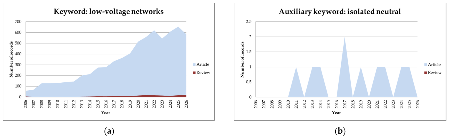
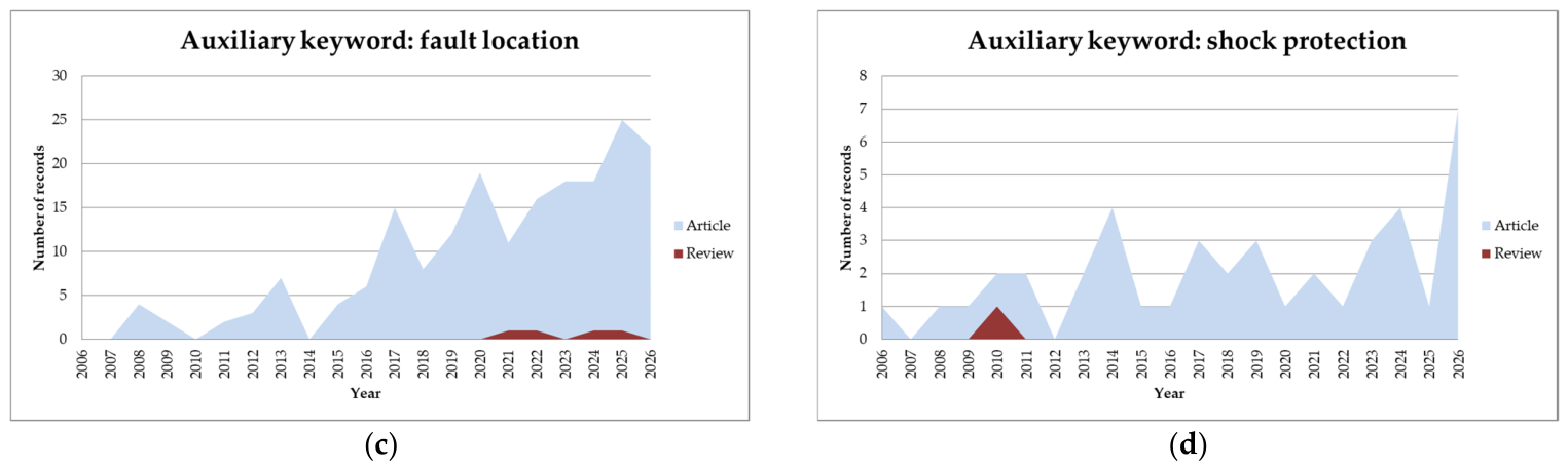
The presented paper has been created as a result of research on insulation condition monitoring systems. Bibliographic analysis conducted on the basis of records in the comprehensive database of abstracts and citations Scopus showed that in the years 2006–2026 there were many works on low-voltage networks, but there are relatively few papers on insulation monitoring systems in these networks, especially in the area of IT networks.
In order to identify co-occurrence of keywords and evolution of the analyzed scope, a comparison of records from 2006–2026 was made for selected keywords. A cross-comparison of the collected data was also carried out, which confirmed the validity of the synthetic attempt to cross-sectional presentation of IT networks along with utilized insulation monitoring systems.
The main keyword that was considered to narrow the search area was ‘low-voltage networks’. This record was then searched for additional keywords: isolated neutral system, fault location, and shock protection. The search has been narrowed down to publications marked ‘article’ and ‘review’ for subject areas limited to ‘engineering’ and ‘energy’, and the search area concerned article titles, abstracts, and keywords. The results are shown in Figure 1.
The identified research gap concerns the need to describe insulation monitoring systems in low-voltage IT networks in a synthetic form of a review-type paper. The presented Scopus analyses confirm that among the papers on low-voltage networks, publications on insulation monitoring systems in low-voltage IT networks constitute a minor percentage of all available records in the database, and at the same time there is a shortage of review-type publications that can offer a comprehensive analysis of the existing literature within a field of study, identifying current gaps or problems.
The paper uses a cross-section of bibliographic items, taking into account the development of insulation monitoring systems, including the latest and older items—especially in areas concerning recognized and successfully used contemporary insulation monitoring devices. The percentage share of individual types of sources used includes 48% of publications in scientific journals and books and 29% of international and national standards and industry guidelines, as well as 23% of publications by leading manufacturers of electrical equipment in the area of interest.

3. Types of Grounding in Low-Voltage Networks

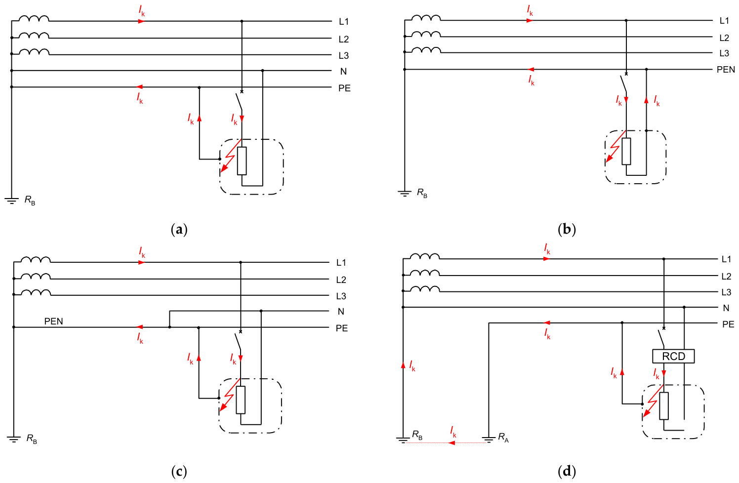
The principles of creating low-voltage network systems and their grounding are described in many publications, e.g., in books [44,45], papers [46,47,48,49], or guides [50,51], but the basic source of information is the standard [13]. There are different types of low-voltage networks as shown in Figure 2, Figure 3, Figure 4 and Figure 5. The following letters may appear in the network system symbol:
the first letter (indicates the connection of the source with the ground):
T—there is a direct connection to the ground of one point, usually the neutral point, and if it is unavailable, the line conductor,
I—indicates that the live parts are isolated from the ground or one point is connected to the ground through a high impedance,
the second letter (indicates connecting the exposed-conductive parts with the ground, usually in consumer installations):
T—there is a direct connection of the exposed-conductive parts with the ground; this must be a ground electrode independent of the ground electrode of the power source,
N—there is a direct connection of exposed-conductive parts with the grounded point of the network power source.
In the TN system, one or two more letters are given to indicate the connection between the protective conductor and the neutral conductor:
S—the protective function is performed by the PE protective conductor separated from the neutral conductor (when the neutral point is not available, the PE conductor is separated from the grounded line conductor),
C—a common PEN (protective earthing–neutral) conductor is used, providing both a protective and a neutral conductor function.
Figure 2 presents solidly grounded low-voltage networks (TN and TT). In the case of TN and TT networks, automatic disconnection of supply should occur in the event of the first ground fault. The condition of effectiveness of protection against electric shock for TN systems is defined by the following expression:
Z sTN U o I a
where:
ZsTN—maximum permissible fault loop impedance,
Uo—nominal line-to-ground voltage,
Ia—tripping current of the protection (circuit-breaker, RCD), i.e., the current ensuring the disconnection of supply within the time required by the standard.
When it comes to the TT network, there are two conditions:
for RCD as a disconnecting device
R A U L I a
for overcurrent protection (circuit breaker, fuse) as a disconnecting device
Z sTT U o I a
where:
RA—maximum permissible resistance of the grounding system of the current-using equipment,
ZsTT—maximum permissible fault loop impedance (in practice it is the sum of RA + RB from Figure 2d),
Uo—nominal line-to-ground voltage,
UL—maximum permissible long-term touch voltage (typically AC 50 V),
Ia—tripping current of the protection (circuit-breaker, RCD), i.e., the current ensuring the disconnection of supply within the time required by the standard.
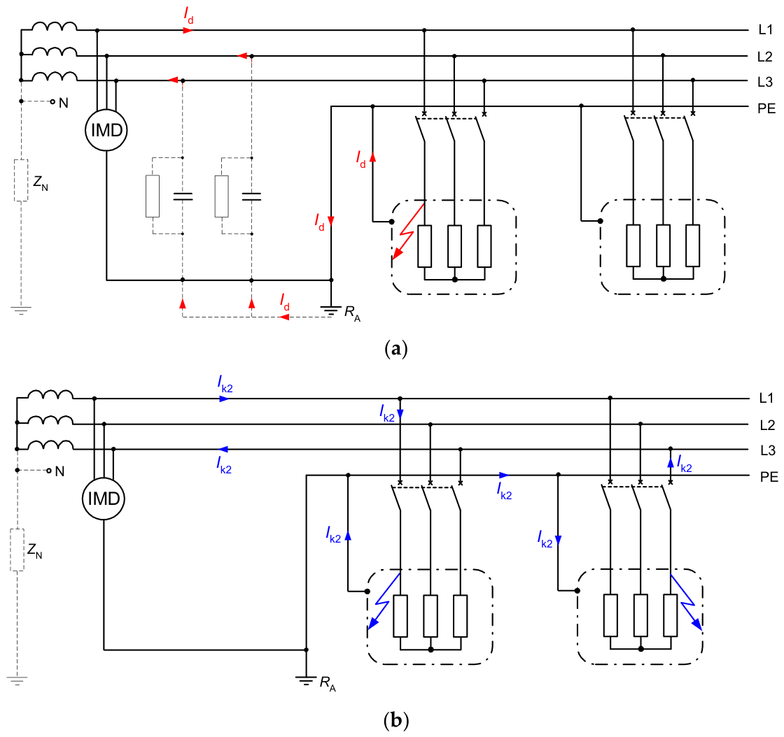
In an isolated neutral system (IT), it is not usually necessary to disconnect the supply on the first ground fault because a low current Id flows through the resistance RA (Figure 3a). Thanks to the low Id current value (in the order of milliamperes or single amperes in large systems), the voltage drop across the RA resistance (and the associated touch voltages) is also low. The operating condition of the network with a single ground fault is as follows:
R A U L I d
where:
RA—maximum permissible resistance of the grounding system of the current-using equipment,
UL—maximum permissible long-term touch voltage (typically AC 50 V),
Id—single ground fault current.
If the power supply in this network is not required to be disconnected after the first ground fault, an insulation monitoring device (IMD) should be installed that will signal (optically and acoustically) this first fault. The maintenance personnel should then locate the ground fault and remove it as soon as possible.
When the exposed-conductive-parts in the IT system are collectively grounded (connected to a common ground electrode RA as in Figure 3), the double ground fault loop is metallic, and the conditions for the effectiveness of the protection against electric shock are as follows:
for a system without a neutral conductor N
Z sIT U 2 I a
for a system with neutral conductor N
Z sIT U o 2 I a
where:
ZsTT—maximum permissible fault loop impedance comprising the line conductor and the protective conductor,
Z′sTT—maximum permissible fault loop impedance comprising the neutral conductor and the protective conductor,
U—nominal line-to-line voltage,
Uo—nominal line-to-neutral voltage,
Ia—tripping current of the protection (circuit-breaker, RCD), i.e., the current ensuring the disconnection of supply within the time required by the standard.
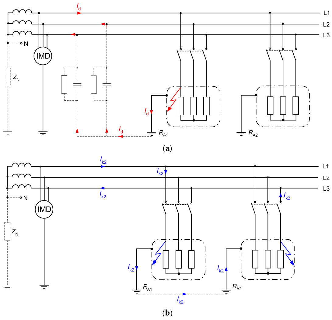
The exposed conductive parts in the IT system can be grounded individually (to separate ground electrodes RA1 and RA2, as in Figure 4), which means that in the case of a double ground fault, the current Ik2 flows through the ground (not in the metallic loop), and for each current-using equipment, the condition of the effectiveness of protection against electric shock is the same as for the TT system (exp. (2a)).
For each type of network system, methods for verifying the effectiveness of protection conditions and the use of appropriate measuring instruments are specified in the standards [52,53,54].
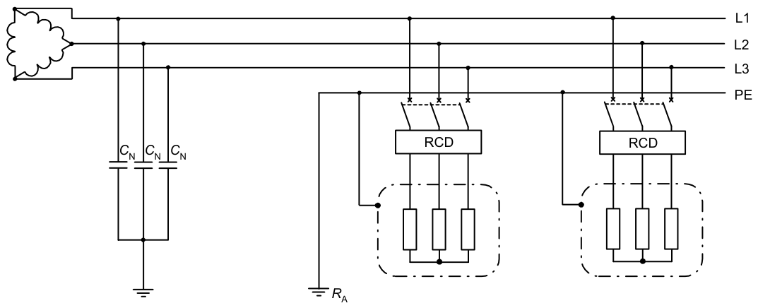
IT networks may not have a natural neutral point (Figure 5), and it may be necessary to disconnect the power supply after the first ground fault (e.g., due to a fire hazard in a given area of the building). It is known that the first ground fault current has a very low value—so low that it is not sufficient to trip even a high-sensitivity 30 mA residual current device (RCD). In this case, an artificial neutral point can be created, which causes the RCD to trip at the first ground fault. The capacitance in one branch of the artificial neutral point circuit should meet the following condition [26,55]:
C N > I Λ n 3 2 π f U
where:
CN—capacitance in one branch of the artificial neutral point circuit,
IΔn—rated residual operating current of the RCD,
U—nominal line-to-line voltage,
F—nominal frequency of the network.

4. Overview of Insulation Monitoring Systems in IT Networks

An IT low-voltage network is typically used to avoid disconnecting the power supply after the first ground fault (continuity of power supply is a priority). In such a case, one of the key elements of the IT network is the insulation monitoring system (IMD—insulation monitoring device according to the present standards and terminology). This system has evolved over the years, and the solutions in this area, which are described in [56,57] and especially in [58], are reviewed further in this section.
The insulation condition monitoring/verification methods applicable to IT networks should meet several criteria that are outlined in [59]. Each of the insulation condition verification methods used should therefore ensure:
Conducting the measurement without interrupting the power supply to the loads.
Conducting the measurement in a way that prevents accidental destruction or damage to the insulation of the tested network.
Conducting the measurement using the minimum amount of additional measuring equipment and electrical devices.
Appropriate level of security for the person carrying out the measurement as well as for the staff operating the network being tested. It has to be noted here that the measurement method used should not violate even the short-term condition of isolating the network from the ground, which in the case of measurement systems having a galvanic connection of live parts to the ground should ensure a sufficiently high impedance of them.
Possibly a short and sufficiently accurate measurement while ensuring a relatively low amount of preparatory activities.
At the same time, the insulation monitoring devices IMDs used in the IT network should meet the following conditions, which determine the effectiveness of measurement/monitoring of all network elements and the maintenance of protection against electric shock at a satisfactory level [60]:
Within a galvanically connected IT network, only one IMD is permitted. The implication of this fact is the need to install additional insulation monitoring systems in individual network areas separated, for example, by a step-down transformer.
The capacitances-to-ground of the IT system should not affect the measured insulation resistance values, except during the transient states. This situation applies only to methods that, due to their operating principle, do not allow the measurement of the capacitive component of the insulation impedance.
In networks with an N neutral conductor, the insulation of this conductor relative to the ground should also be measured.
The use of power electronic converter devices in the system requires that the converter outputs be also monitored.
Due to the fact that the insulation condition monitoring methods also include measurements made on the network in a voltage-free state (off-line monitoring), in the following part of the paper only methods are described, the use of which does not require disconnecting the power supply.
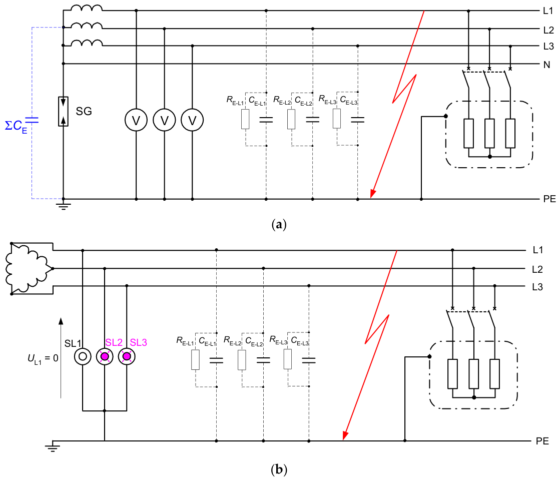
One of the first/early methods for detecting the first ground fault in an IT network was the three-voltmeter method (Figure 6a). In normal operation, all voltmeters indicate line-to-ground voltage. If one phase is ground-faulted, the voltage indicated by the voltmeter connected to that phase decreases, and the voltage in the remaining voltmeters increases. This system, however, has drawbacks because it does not detect all faults, e.g., an insulation fault between the neutral conductor and ground. Another solution to this idea is the arrangement shown in Figure 6b. This is a common use in a three-wire system when the transformer on the low-voltage side has a delta configuration—signal lamps (SL1, SL2, SL3) are used instead of voltmeters [61].
In conditions without a ground fault in the network, all three lamps illuminate with similar brightness. In the event of a ground fault, for example, in phase L1 (Figure 6b), lamp SL1 dims, while the remaining two lamps, SL2 and SL3, illuminate even brighter than in normal operation. However, the system will not detect, for example, a ground fault in all three phases. This solution is still being used, among others, on board older ships, and its popularity, for example in American shipbuilding, can be evidenced by information about the program for searching for an alternative solution dated only to 2021 [62]. The advantage of this method is its undoubted simplicity and the visual possibility of quickly assessing the insulation resistance state of a healthy network or in a single-phase ground fault state.
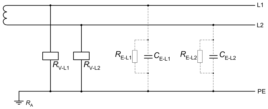
A contemporary extension of the voltage measurement method in assessing the insulation condition is the use of voltage relays connected between the phase conductor and the ground. Figure 7 illustrates how to connect relays in an insulation condition monitoring system in an AC network.
In the discussed system, undervoltage or overvoltage relays can be used, and it should be noted that they signal insulation damage when the set voltage alarm value is exceeded. Due to the fact that the relay may be excited in a situation of significant asymmetry in the distribution of the phase capacitances of the system, its usefulness in assessing the insulation state may be incomplete. Moreover, according to the interpretation of standards [11,18], such a system does not meet all the requirements for devices for monitoring the insulation condition [58]. The undoubted advantage of the presented monitoring system is the ability to easily turn on the alarm system using auxiliary relay contacts in case of a ground fault detection.
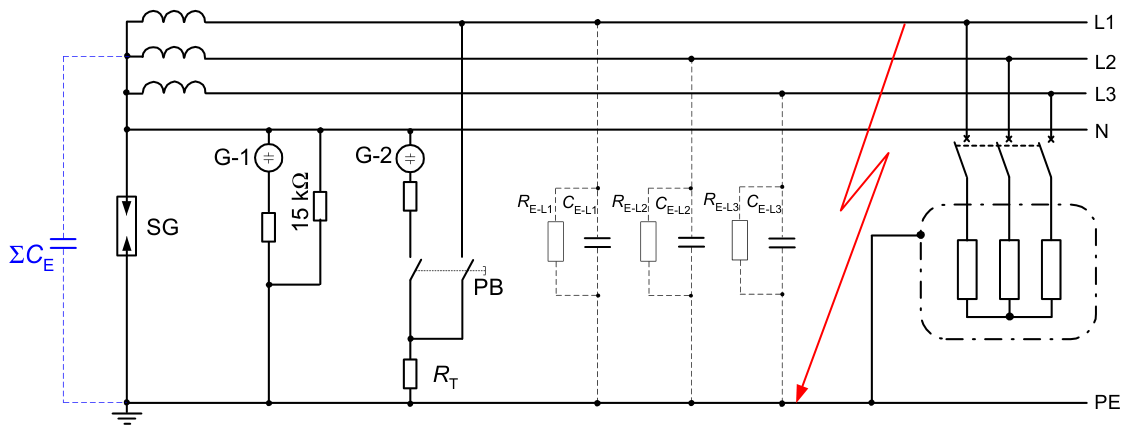
The system shown in Figure 8 is an insulation testing solution used by Siemens before 1939. This solution also allows for the determination of protective spark-gap (SG) failure. A ground fault in any phase causes the G-1 glow lamp to light up, because there will be a voltage between ground PE and neutral N. In turn, the G-2 glow lamp, RT resistance, and PB button system are used to verify the correctness of the SG. If the G-2 lamp lights up after pressing the PB button, the SG is in good working order. If there is a short-circuit in the SG, the G-2 lamp will not light up—there is no proper voltage between neutral N and ground PE.
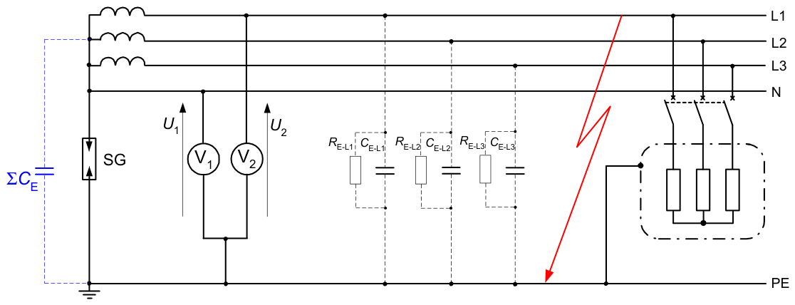
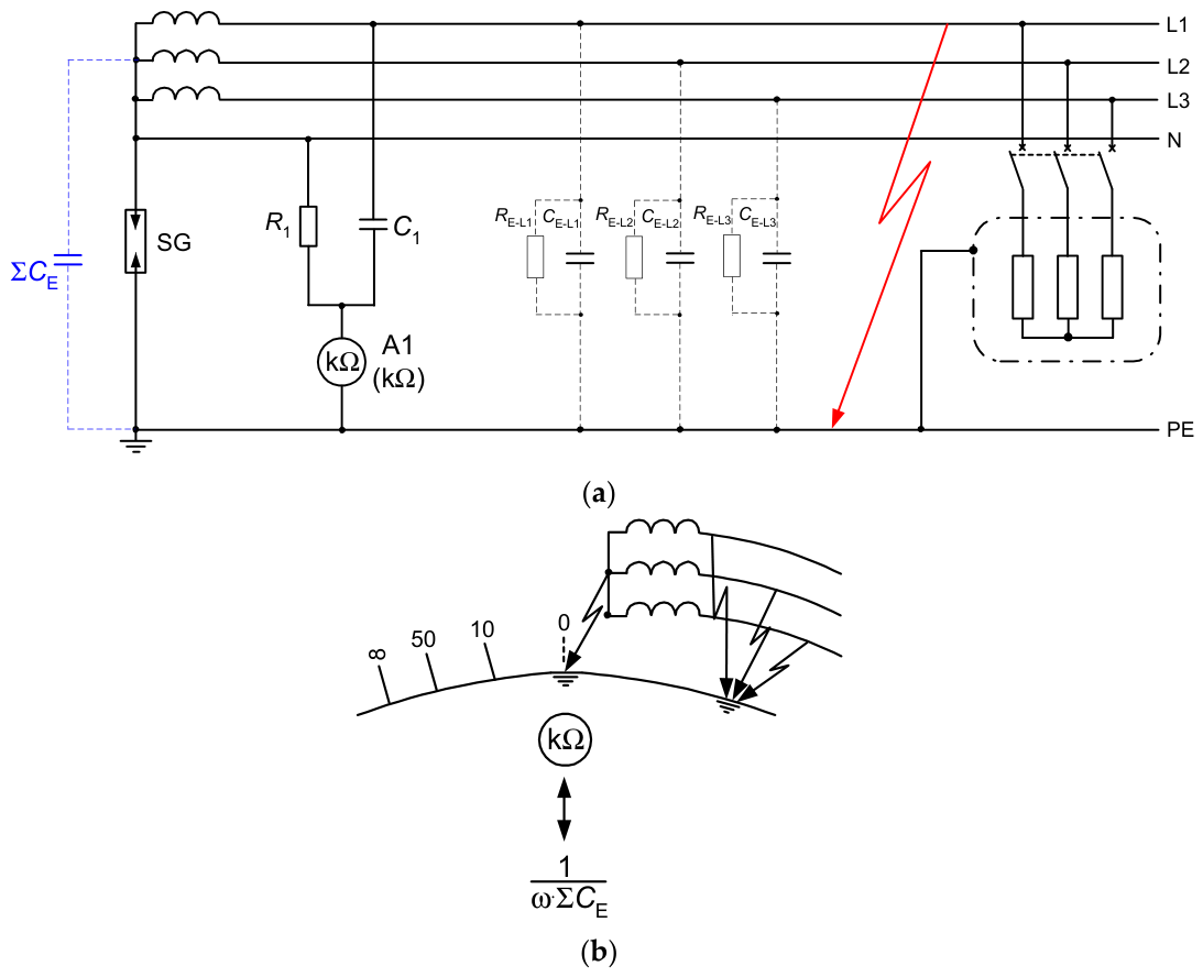
The ground fault detection method from around 1933 shown in Figure 9 is based on two voltmeters. This method utilizes the different voltage indications of voltmeters V1 and V2 as the effect of the different neutral-to-ground vs. phase-to-ground capacitances. The resulting neutral-to-ground capacitance is approximately ∑CE = 3CE-L and is connected in parallel with voltmeter V1 (voltage U1). The voltage U2 corresponds to the capacitance CE-L1. Therefore, the inequality U1 < U2 always holds. The practical application of this solution is shown in Figure 10a. The voltmeters are replaced by elements R1 and C1, and the ammeter A1 is used to indicate “kΩ”. The left side of the scale is marked in capacitive kΩ. An indication in this part of the scale informs about the absence of a ground fault. A short circuit to ground of the neutral point resulted in an indication at point “0”, whereas a phase-to-ground fault resulted in an indication on the right side of the scale (Figure 10b).
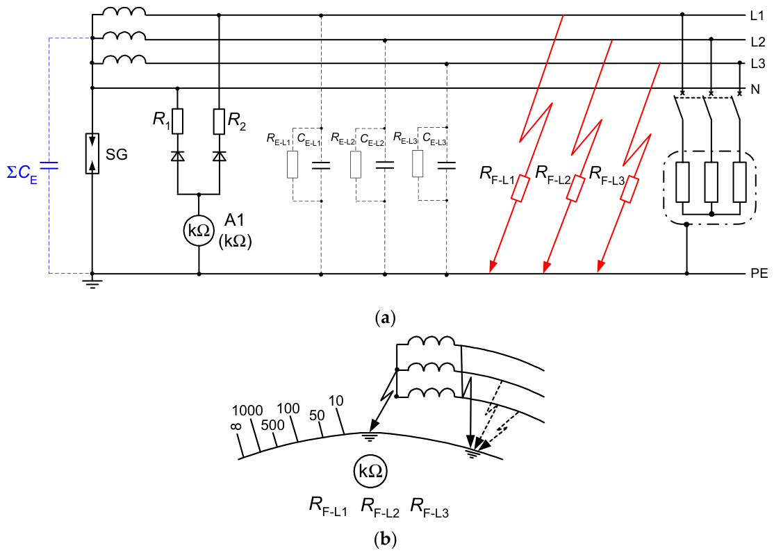
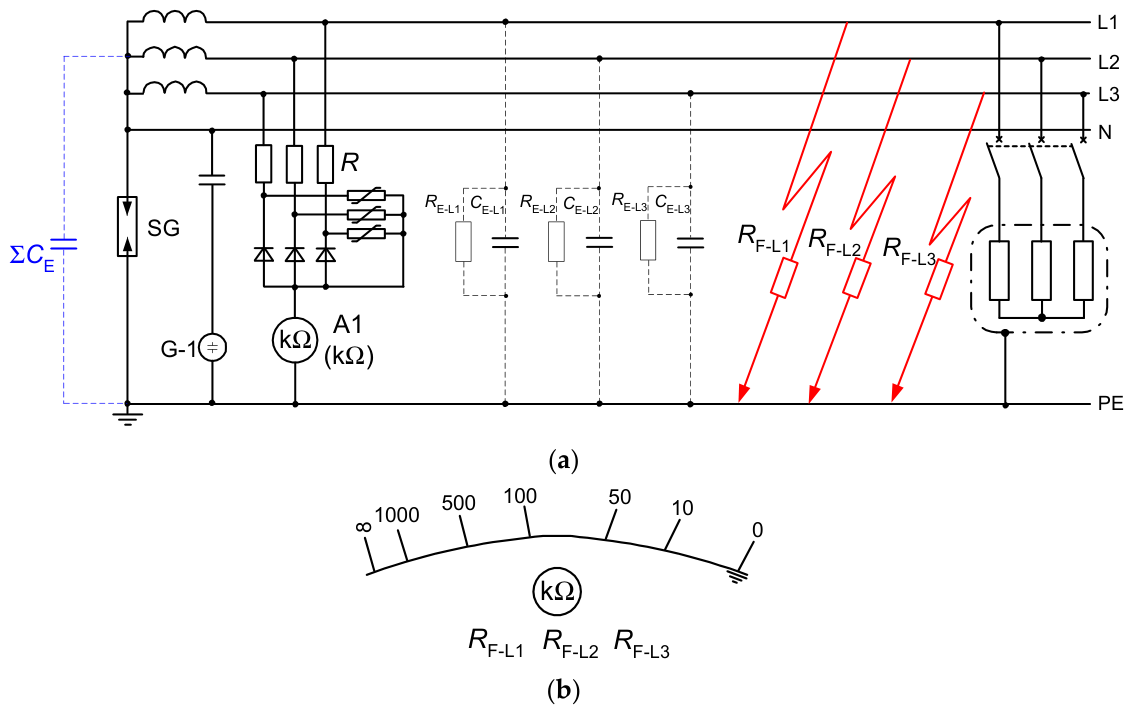
Another historical solution of the insulation monitoring device is shown in Figure 11. It allowed the detection of ohmic ground faults. In this solution, high-resistance resistors R1, R2, and rectifiers were used (Figure 11a). By using a rectified (DC) signal, it was possible to measure only the resistance of the insulation (without taking into account the network capacitance). The left side of the scale (Figure 11b) indicated the insulation resistance level, the center indicated the neutral-to-ground fault, and the right side indicated the phase-to-ground fault.
Figure 12 shows a modified (compared to Figure 11) insulation monitoring device in which a symmetrical circuit with R resistors is used. This system is additionally equipped with varistors that stabilize the DC test voltage signal. Both methods (Figure 11 and Figure 12) allowed for the indication of the absolute value of the insulation resistance to ground during network operation—it was therefore real, continuous insulation monitoring.
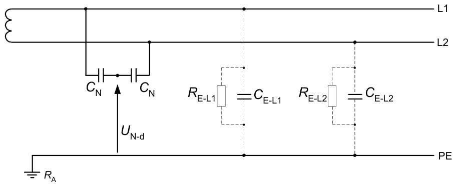
A method using a similar operating principle as the voltage measuring method described above (Figure 12) is also a method used, among others, in the mining industry, which involves measuring the zero component of the voltage generated in situations of asymmetry. Such asymmetry may be caused by different values of the phase capacitance of the network conductors relative to the ground [63]. The appearance of a zero component in the case of system asymmetry is a phenomenon similar to systems using the so-called artificial zero method, in which the voltage between the measuring point and the ground is measured (Figure 13). At the same time, this method does not allow, similarly to the methods described above, to determine the exact location of the ground fault, which makes it necessary to use additional methods of ground fault locating or selectively switch off sections of the monitored circuit.
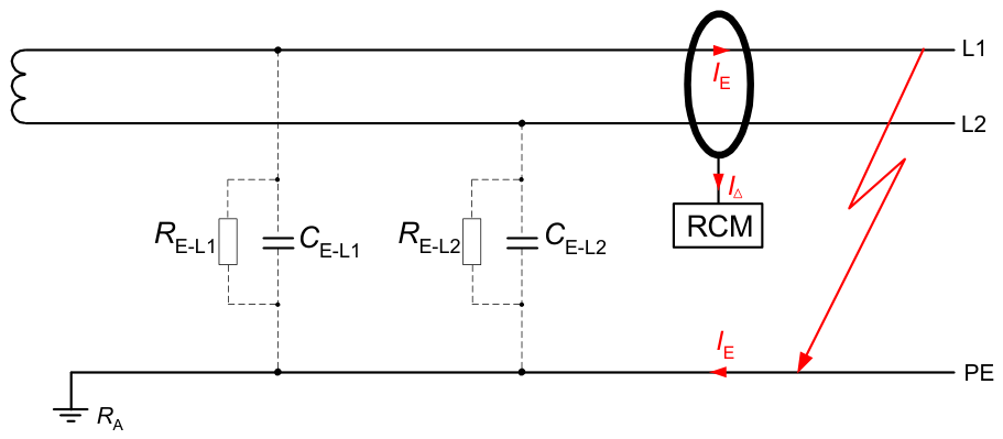
In IT systems, as in TN systems, methods based on the measurement of residual currents are also used (Figure 14). The use of residual current relays, similarly to complementary electric shock protection systems in TN networks, measures the residual current, i.e., the algebraic sum of the values of the electric currents (at the same time) in all live conductors. The residual current, as a quantity derived from the state of insulation, indicates a decrease in insulation-to-ground resistance, which results in the alarm being initiated. An important element of the proper operation of this system is the need to select an RCM with specific residual current characteristics. Changing the power quality conditions in the monitored circuit, especially in terms of, e.g., the appearance of a DC component or higher-order harmonics, may cause the RCM to not respond correctly to the measured residual current.
The methods of monitoring the insulation resistance (impedance) of IT networks presented above are based on measurements and indications of parameters occurring naturally in the system. These are the so-called passive methods. Their undoubted advantages are the ability to indicate a decrease in insulation resistance without using additional test signals introduced into the system. The operation of these methods is based on passive measurement of parameters and does not affect in any way the operation of devices, apparatus, and the network itself. Their disadvantage is in most cases their sensitivity to changes in ground capacitance and the possible creation of a galvanic connection between the live parts of the system and the ground.
Another group of methods for assessing the condition of insulation-to-ground are active methods that inject a specific signal into the tested network. Selected methods using a measurement signal fed to the system from an external source are presented below.
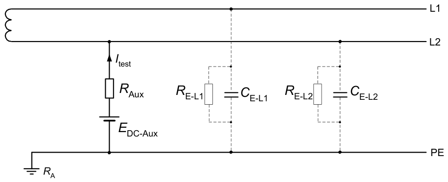
The simplest method using an external measurement signal is to use an auxiliary DC current signal [35,64]. Complete impedance-to-ground consists of capacitances-to-ground CE-L1, CE-L2, and resistances-to-ground RE-L1, RE-L2 (Figure 15). The DC current method allows only the resistive components to be determined. An auxiliary voltage source EDC-Aux in this type of system is connected between the live conductor of the network and the ground (Figure 15), forcing current Itest to flow through a resistor RAux and insulation resistances of the IT system. This makes it possible to determine the value of the actual insulation resistance of the power system, having known parameters of the test system (EDC-Aux, Itest, RAux). It should be noted here that the possibility of determining the value of the resistive component of the insulation impedance does not provide complete information about the insulation state of the network in this case. The inability to determine the capacitive component may—in the case of significant leakage values—result in reduced electrical safety to the personnel when critical values of ground capacitances are exceeded, while at the same time failing to raise the insulation status alarm.
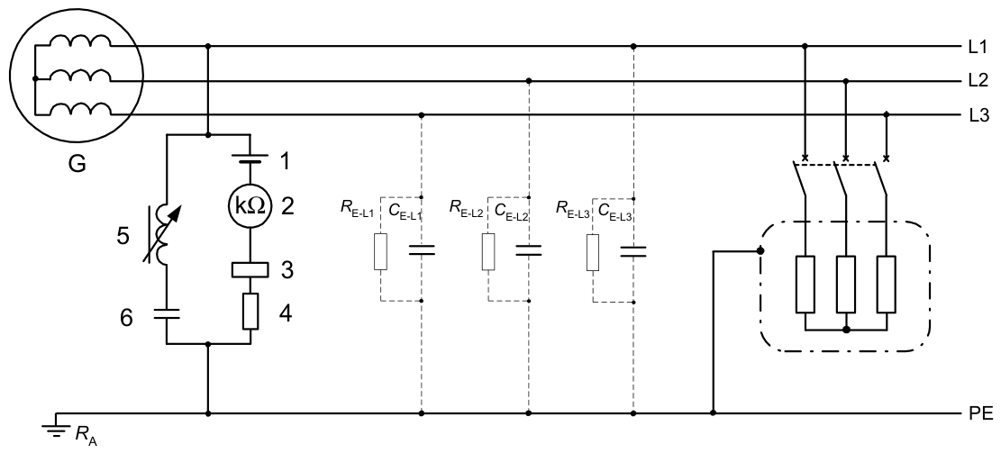
The methods utilizing DC test current are, among others, applied in the shipbuilding industry. Apart from the fact that the regulations on the construction of distribution systems of ship networks [65] allow the use of network systems with a grounded neutral point (without using the ship’s hull as a return path), the main system used in ship low-voltage networks is the isolated neutral system. Figure 16 presents a typical IT network in ships with an insulation status monitoring system. The operation of the presented system involves injecting a test signal (DC test current) between the live part and the ground. The signal is returned to the IMD by network leakage. When the insulation resistance drops below the set value (e.g., due to a ground fault), the system signals an alarm state. The suppressor and blocking capacitor used in the system allow for compensation of leakage currents derived from ground capacitances. For networks constructed in this way as an IT system, the regulations of classification societies, e.g., [65,66] specify the value of the minimum permissible insulation resistance of the cable network of ships in operation at a level from 0.3 Ω per 1 V (for voltages below 125 V) through 1.0 Ω per 1 V (for voltages 125–500 V) up to 2000 Ω per 1 V of nominal voltage (for voltages above 500 V).
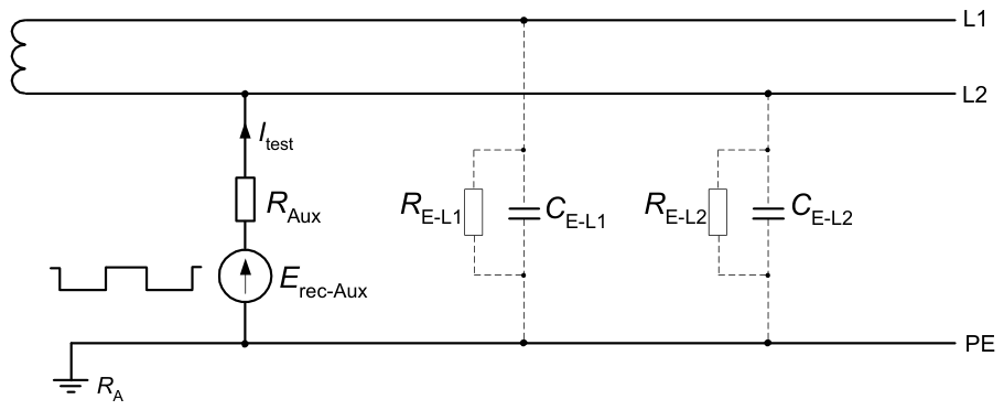
Methods using an external measurement signal (Figure 17) also include those in which the test signal Itest is generated periodically (rectangular pulses) by an alternating voltage source Erec-Aux [67,68]. The result of switching on such a voltage source between one of the network live conductors and the ground is the periodic appearance of a characteristic waveform in the network, which allows for obtaining a network response to this signal. Appropriate selection of the duration of the rectangular pulse superimposed on the network voltage and current waveform allows the test (rectangular) current to flow through the resistance-to-ground and the possibility of determining the value of this resistance.
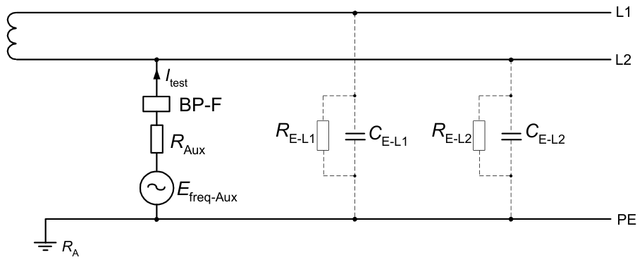
A method with a similar measurement system architecture to the one described above (Figure 17) is a method using an auxiliary alternating voltage source with a frequency different from the frequency of the monitored network [69,70]—Figure 18. The presence of this frequency in the current signal Itest allows the measurement of this signal to be used to detect ground faults and determine the values of the insulation impedance components.
In complex, multi-branch IT low-voltage systems, only ground fault detection is not sufficient. The location of the fault (the faulty branch) must also be identified, and this is difficult. The classic approach involves sequentially shutting down sections of the installation and step-by-step searching for the damaged circuit. This method requires time-consuming shutdown of individual areas. One of the methods for detecting this fault point is the method described in paper [71]. This method uses a test signal superimposed on the basic voltage waveform in the network in the form of a modulated signal or a constant current signal. Alternatively, a portable fault locator can be used. The portable systems described in [72,73,74,75,76] operate on a similar principle. They include test signal generators of various natures and clamp meters adapted to work in AC and DC networks.
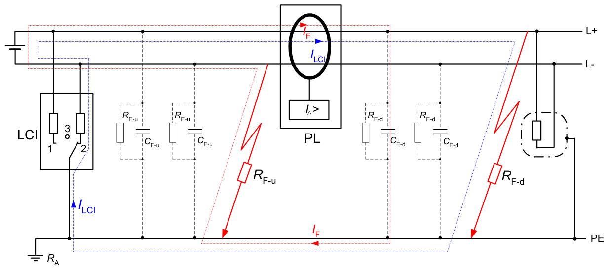
The use of a portable device and clamp meters enables ground fault detection to be performed without interruption in power supply, incorporating a signal generator into the operating network and searching for the fault location. The use of a wide range of measuring clamps enables operation in networks with a rated current of up to 1000 A [75,76] and detection of residual currents (resulting from a ground fault) from a value of 0.2 mA [73]. Figure 19 shows a typical connection of a portable set to ground fault locations in a three-phase AC IT network, and Figure 20 shows the cycle flow of the test pulse [77].
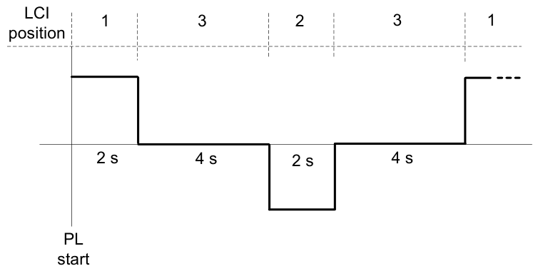
The working principle of the presented fault location system is based on briefly closing the fault circuit using a defined resistance, which is a part of locating current injector (LCI)—Figure 19. The locating current ILCI periodically injected to the network is generated by LCI, and it is limited in amplitude and time (Figure 20). Network live parts are alternately connected to ground via defined resistance. The resulting test current depends on the size of the insulation fault RF-d and the network voltage. The locating current ILCI pulse flows from the LCI through the live parts to the insulation fault RF-d by the shortest route. From there it flows via the insulation fault and the ground back to the LCI. This pulse is detected by the insulation fault locator (PL) in the insulation fault path, allowing the detection of downstream ground faults.
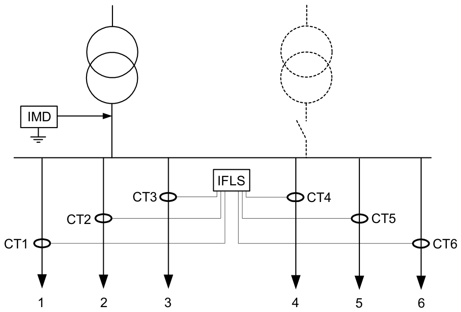
In the most complex IT networks, IMDs with insulation fault location systems (IFLS) are used. In this solution, current transformers are installed in the appropriate branches of the IT network and connected to a concentrator that collects signals from these transformers (Figure 21). This allows for continuous monitoring of the insulation resistance and immediate detection/location of ground faults.
In IT networks, close attention must also be paid to the level of capacitance-to-ground—it is related to the value of the current that can flow through the human body. The subject is presented in more detail in papers [60,64,79], in which the authors report the problem of increasing risk of electric shock in the case of networks with high phase capacitance relative to the ground. For example, in ship IT networks, the capacitance-to-ground values presented in studies of vessel systems manufactured between 1976 and 1994 varied from 0.53 μF to 4.16 μF for 3 × 440 V networks and from 0.44 μF to 21.7 μF for 3 × 230 V networks [64]. It should be noted that the safe value of capacitance-to-ground in a ship IT network is specified in [39] and called the critical capacitance (0.14 μF) for a network with a nominal voltage of 3 × 400 V.
The issue of the occurrence of high capacitances to ground is the reason for searching for active methods of compensating these capacitances. However, the solutions of compensators indicated in the literature [60,64,79,80]—despite demonstrating their effectiveness during research—have not found wider practical application due to the lack of legal regulations on the need to use them in IT networks. For example, in networks with an isolated neutral point used in shipbuilding, the regulations considering the operation of such networks [65,66,81,82] ignore the problem of large capacitances-to-ground due to the difficulties in reducing their value to a level safe for operation.
The presence of capacitances to ground and their value depend on many factors, such as the length of the cable line, the presence of anti-interference filters, or even changes in temperature and humidity. These factors have a significant impact on the state of protection against electric shock in all applications of IT systems, as indicated among others by papers [59,83]. The authors of these papers also emphasize that IT networks with numerous cables of considerable lengths are dangerous for humans (due to high capacitance) despite maintaining a good state of insulation resistance.
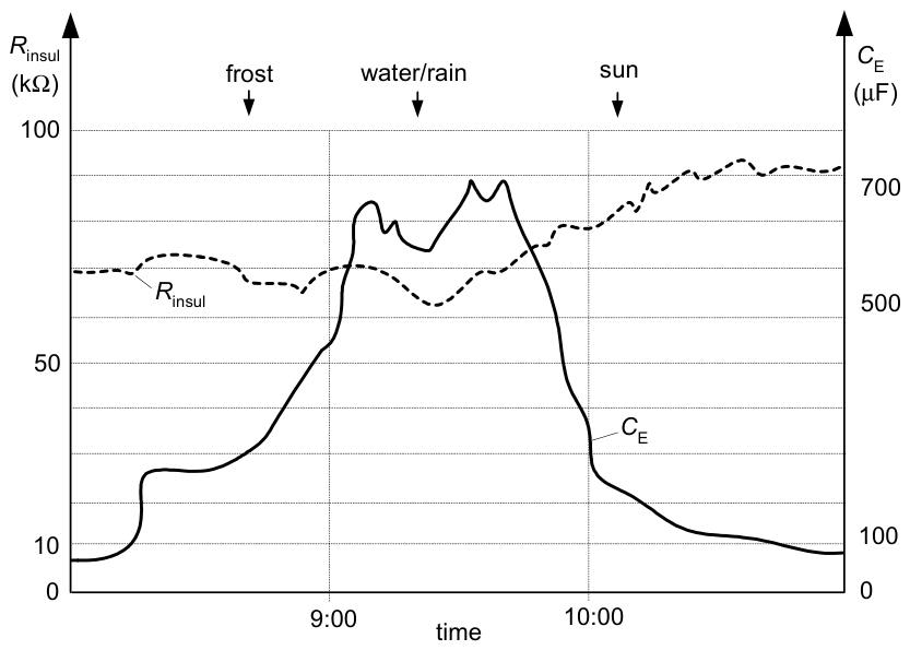
The problem described above also concerns PV farms, which are systems with very high capacitance to the ground. Furthermore, in PV farms, this capacitance varies throughout the day depending on atmospheric conditions. Daily changes in insulation resistance are also observed. Figure 22 shows variation of the capacitance-to-ground and insulation resistance throughout the day for a 15 MW PV farm. Moreover, IMDs have to be adapted to such high capacitances—the catalog card [84] indicates that the IMD is adapted to networks with capacitances of up to 4000 μF.
In the case of PV farms, special attention should be paid to the IMD threshold settings. According to the source [18], in PV farms with a rated power of 1 MW or more, the natural insulation resistance under unfavorable atmospheric conditions can be as low as 1 kΩ (Table 1). This is a very low natural value; only below this value should the IMD react.

5. Discussion and Conclusions

Insulation monitoring and fault location solutions for IT networks presented above become crucial elements responsible for the reliability and safe operation of the network and provide the necessary factor in ensuring that the fundamental advantages of the network are preserved. These advantages of IT networks include:
Possibility of long-term operation with a single-phase ground fault (it should be noted here that the minimum time for removing such a fault is not specified). Networks of this type enable the increase of the reliability of the power supply (can work with a single ground fault).
Relatively low values of the ground current (compared to TN and TT systems), which ultimately results in increased fire safety.
Limitation of the body current value in the event of body contact with the wire of one phase while maintaining high values of the insulation impedance of the remaining phases.
Possibility of checking the insulation resistance status and using monitoring/measurement devices with alarm and disconnection of supply functions in the event of detecting single-phase ground faults or exceeding the minimum permissible insulation resistance values of the monitored circuits.
The most important disadvantages of IT systems are related to, among others:
The lack of possibility of precise location of the place where a ground fault occurs—in practice such a place is located by selective and area-based disconnection of loads, which—in the case of a network with a significant spatial span and a large number of loads—relatively extends the duration of the fault.
The need to ensure high service standards and continuous monitoring of the insulation condition.
Considering the above features of the IT network and taking into account the technical characteristics of the described solutions, a summary has been made and presented in Table 2 and Table 3. Letters A, B, C, etc. in Table 3 correspond to methods referenced in Table 2, point IV. For clarity of comparison, methods with similar characteristics are grouped.
The presented characteristics of the considered insulation monitoring systems in low-voltage IT networks indicate the main features of modern measurement systems, which include their simplicity of construction, the possibility of continuous operation, and the quantitative assessment of insulation impedance—especially in relation to application areas in which the values of insulation impedance (resistance) are regulated by law.
The multitude of solutions and the historical outline of insulation monitoring systems indicate the need for continuous development and search for efficient measurement systems, especially in the era of wide development of network loads with a non-linear nature of operation, which may affect the operation of the previously used IMD by introducing distortions in the leakage circuits, in a manner analogous to the problems of using RCD, indicated in [26,29]. This leads to the conclusion that, despite the development of insulation monitoring techniques in IT networks, there are still gaps and challenges in this area.

6. Future Directions

The insulation monitoring systems presented in this paper are characterized, in addition to their undoubted advantages, by a number of disadvantages, including limited use for determining the actual value of insulation impedance at leakages originating in the ground capacitances of the network and the introduction of distortions into the network in the form of test currents.
These findings lead to potential future directions that can stimulate development in IMD and IFLS technologies. The proposed direction for further research should include systems in which greater emphasis will be placed on combining the features of insulation condition monitoring and determining its physical parameters (resistance-to-ground as well as capacitance of the network), while at the same time being able to indicate the locations of ground faults, operating quickly, maintaining the greatest possible simplicity of the measuring system and ensuring galvanic separation of the network live parts and the ground during the measurement. In view of the widespread use of large-scale PV systems, it is important to develop and apply active IMD methods that allow for quick and precise estimation of the ground insulation resistance (also as weather conditions change) in order to avoid unnecessary outages of these systems and economic losses.

Author Contributions

Conceptualization, A.F. and S.C.; methodology, A.F. and S.C.; validation, A.F. and S.C.; formal analysis, S.C.; investigation, A.F.; resources, A.F. and S.C.; data curation, A.F.; writing—original draft preparation, A.F. and S.C.; writing—review and editing, A.F. and S.C.; visualization, S.C.; supervision, S.C. All authors have read and agreed to the published version of the manuscript.

Funding

This research received no external funding.

Data Availability Statement

Data are contained within the article.

Conflicts of Interest

The authors declare no conflicts of interest.

References

  1. Zaitseva, E.; Levashenko, V. Reliability engineering in healthcare: Opportunities and challenges. Reliab. Eng. Syst. Saf. 2026, 267, 111933. [Google Scholar] [CrossRef] [Scilit]
  2. Zaitseva, E.; Levashenko, V.; Rabcan, J. Application of Structure Function Based Reliability Analysis in Medical Domain. In Proceedings of the 30th European Safety and Reliability Conference, ESREL 2020 and 15th Probabilistic Safety Assessment and Management Conference, PSAM 2020, Venice, Italy, 1–5 November 2020. [Google Scholar]
  3. HD 60364-7-710:2012; Low-Voltage Electrical Installations—Part 7-710: Requirements for Special Installations or Locations—Medical Locations. European Committee for Electrotechnical Standardization: Brussels, Belgium, 2012.
  4. HD 60364-5-56:2018; Low-Voltage Electrical Installations—Part 5-56: Selection and Erection of Electrical Equipment—Safety Services. European Committee for Electrotechnical Standardization: Brussels, Belgium, 2018.
  5. EN 1828:2024; Lighting Applications—Emergency Lighting for Buildings. European Committee for Electrotechnical Standardization: Brussels, Belgium, 2024.
  6. IEEE Draft Recommended Practice for Electrical Installations on Shipboard—Safety Considerations. P45.5/D5; Institute of Electrical and Electronics Engineers: New York, NY, USA, 2014.
  7. Buticchi, G.; Bozhko, S.; Liserre, M.; Wheeler, P.; Al-Hadad, K. On-board Microgrids for the More Electric Aircraft—Technology Review. IEEE Trans. Ind. Electron. 2019, 66, 5588–5599. [Google Scholar] [CrossRef] [Scilit]
  8. IEC TS 60479-1:2016; Effects of Current on Human Beings and Livestock—Part 1: General Aspects. International Electrotechnical Commission: Geneva, Switzerland, 2016.
  9. Lanzisero, T. Electric shock hazards—Risk assessment and safety management. In Proceedings of the IEEE Symposium on Product Compliance Engineering Proceedings, Portland, OR, USA, 5–7 November 2012. [Google Scholar] [CrossRef] [Scilit]
  10. EN 61140:2016; Protection Against Electric Shock—Common Aspects for Installation and Equipment. European Committee for Electrotechnical Standardization: Brussels, Belgium, 2016.
  11. HD 60364-4-41:2017; Low-Voltage Electrical Installations—Part 4-41: Protection for Safety—Protection Against Electric Shock. European Committee for Electrotechnical Standardization: Brussels, Belgium, 2017.
  12. HD 60364-5-53:2022; Low-Voltage Electrical Installations—Part 5-53: Selection and Erection of Electrical Equipment—Switchgear and Controlgear. European Committee for Electrotechnical Standardization: Brussels, Belgium, 2022.
  13. HD 60364-1:2008; Low-Voltage Electrical Installations—Part 1: Fundamental Principles, Assessment of General Characteristics, Definitions. European Committee for Electrotechnical Standardization: Brussels, Belgium, 2008.
  14. Mukhtaruddin, A.; Azizan, M.M.; Ariffin, M.F. Review of insulation monitoring and fault locating devices for ungrounded low voltage network: Commercial products, patents, research and innovation. Electr. Power Syst. Res. 2025, 242, 111464. [Google Scholar] [CrossRef] [Scilit]
  15. Jullien, F.; Heritier, I. The IT Earthing System (Unearthed Neutral) in LV. Cahier Technique no. 178, Schneider Electric, 1999. Available online: https://sti.eduscol.education.fr/sites/eduscol.education.fr.sti/files/ressources/techniques/3336/3336-ect178.pdf (accessed on 16 June 2025).
  16. Technical Aspects IT Systems. Bender, Grünberg, Germany. 2020. Available online: https://fournais-bender.dk/storage/TechnAspects-IT-systems.pdf (accessed on 4 February 2026).
  17. IEC 61557-1:2019; Electrical Safety in Low Voltage Distribution Systems up to 1000 V AC and 1500 V DC—Equipment for Testing, Measuring or Monitoring of Protective Measures—Part 1: General Requirements. International Electrotechnical Commission: Geneva, Switzerland, 2019.
  18. IEC 61557-8:2014; Electrical Safety in Low Voltage Distribution Systems up to 1000 V a.c. and 1500 V d.c.—Equipment for Testing, Measuring or Monitoring of Protective Measures—Part 8: Insulation Monitoring Devices for IT Systems. International Electrotechnical Commission: Geneva, Switzerland, 2014.
  19. IEC 61557-9:2014; Electrical Safety in Low Voltage Distribution Systems up to 1000 V a.c. and 1500 V d.c.—Equipment for Testing, Measuring or Monitoring of Protective Measures—Part 9: Equipment for Insulation Fault Location in IT Systems. International Electrotechnical Commission: Geneva, Switzerland, 2014.
  20. IEC 61557-15:2014; Electrical Safety in Low Voltage Distribution Systems up to 1000 V a.c. and 1500 V d.c.—Equipment for Testing, Measuring or Monitoring of Protective Measures—Part 15: Functional Safety Requirements for Insulation Monitoring Devices in IT Systems and Equipment for Insulation Fault Location in IT Systems. International Electrotechnical Commission: Geneva, Switzerland, 2014.
  21. Sun, A.; Xu, B.; Wang, W.; Yip, T.; Li, F. Distributed earth fault detection method for low voltage distribution networks using phase voltage synchronization. Int. J. Electr. Power Energy Syst. 2025, 169, 110771. [Google Scholar] [CrossRef] [Scilit]
  22. Zhu, H.; Wu, C.; Xie, Y.; Zhou, Y.; Liao, X.; Li, J. Research on DC Electric Shock Protection Method Based on Sliding Curvature Accumulation Quantity. Electronics 2024, 13, 3336. [Google Scholar] [CrossRef] [Scilit]
  23. HD 60364-7-712:2016; Low-Voltage Electrical Installations—Part 7-712: Requirements for Special Installations or Locations—Photovoltaic (PV) Systems. European Committee for Electrotechnical Standardization: Brussels, Belgium, 2016.
  24. Czapp, S. On protection against electric shock in photovoltaic farms (Original in Polish: W sprawie ochrony przeciwporażeniowej w farmach fotowoltaicznych). Inf. Normach Przep. Elektr. 2025, 304–305, 45–53. [Google Scholar]
  25. Stanisławski, W. Ochrona Przeciwporażeniowa w Lądowych i Morskich Sieciach Elektroenergetycznych Niskiego Napięcia. Zesz. Nauk. AMW 2004, XLV, 135–148. Available online: https://bibliotekanauki.pl/articles/222372.pdf (accessed on 4 May 2026).
  26. Czapp, S. Residual Current Devices: Selection, Operation, and Testing; Academic Press: London, UK, 2022; ISBN 9780323897839. [Google Scholar] [CrossRef] [Scilit]
  27. IEC 61008-1 2010; Residual Current Operated Circuit-Breakers Without Integral Overcurrent Protection for Household and Similar Uses (RCCBs)—Part 1: General Rules. International Electrotechnical Commission: Geneva, Switzerland, 2010.
  28. IEC 62423:2009; Type F and Type B Residual Current Operated Circuit-Breakers with and Without Integral Overcurrent Protection for Household and Similar Uses. International Electrotechnical Commission: Geneva, Switzerland, 2009.
  29. Czapp, S.; Tariq, H.; Cieslik, S. Behavior of residual current devices at earth fault currents with DC component. Sensors 2022, 22, 8382. [Google Scholar] [CrossRef] [Scilit]
  30. Czapp, S.; Tariq, H. Behavior of residual current devices at frequencies up to 50 kHz. Energies 2021, 14, 1785. [Google Scholar] [CrossRef] [Scilit]
  31. Nguyen, T.G.; Nguyen, T.K.; Ngo, X.C.; Do, N. Research on Electric Leakage Protection to Improve Electrical Safety in Underground Mining in Vietnam. Inżynieria Miner. 2023, 2, 209–214. [Google Scholar] [CrossRef] [Scilit]
  32. IEC 62020-1:2020; Electrical Accessories—Residual Current Monitors (RCMs)—Part 1: RCMs for Household and Similar Uses. International Electrotechnical Commission: Geneva, Switzerland, 2020.
  33. HD 60364-5-551:2010; Low-Voltage Electrical Installations—Part 5-55: Selection and Erection of Electrical Equipment—Other Equipment—Clause 551: Low-Voltage Generating Sets. European Committee for Electrotechnical Standardization: Brussels, Belgium, 2010.
  34. Electrical Safety for Mobile Generators, BENDER. Available online: https://www.bender.de/en/know-how/applications/technical-paper-electrical-safety-for-mobile-generators (accessed on 16 June 2025).
  35. Olszowiec, P. Insulation Measurement and Supervision in Live AC and DC Unearthed Systems, 2nd ed.; Lecture Notes in Electrical Engineering; Springer International Publishing: Cham, Switzerland, 2014; Volume 314. [Google Scholar] [CrossRef] [Scilit]
  36. Wen, J.; Zeng, T.; Yan, F.; Chen, W. Research on ON-LINE Insulation Monitoring Instrument of IT Power System in the Down Hole Mine. IOP Conf. Ser. Mater. Sci. Eng. 2018, 394, 042081. [Google Scholar] [CrossRef] [Scilit]
  37. Wiatr, J. Ochrona Przeciwporażeniowa w Sieci o Układzie Zasilania IT, elektro.info 3/2020, s. 56–60, Warszawa 2020. Available online: https://www.elektro.info.pl/artykul/ochrona-przeciwporazeniowa/188700,ochrona-przeciwporazeniowa-w-sieci-o-ukladzie-zasilania-it (accessed on 5 May 2026).
  38. Nelson, J.P.; Sen, P.K. High-Resistance Grounding of Low-Voltage Systems: A Standard for the Petroleum and Chemical Industry. IEEE Trans. Ind. Appl. 1999, 35, 941–948. [Google Scholar] [CrossRef] [Scilit]
  39. Nowak, T. Opis Wybranych Zagadnień Związanych z Zagrożeniami Podczas Eksploatacji Sieci z Izolowanym Punktem neutralnym. Sci. J. Gdyn. Marit. Univ. 2018, 103, 57–72. [Google Scholar]
  40. Grounded vs. Ungrounded Lines in an Operation Room. BENDER. Available online: https://www.benderinc.com/blog/post/grounded-vs-ungrounded-lines-in-an-operating-room/ (accessed on 2 May 2026).
  41. Lee, H.-M.; Chae, W.-K.; Kim, W.-H.; Kim, J.-E. Cooperative Use of IMD and GPT in a 3-Phase Ungrounded Distribution System Linked to a Transformerless Photovoltaic Power Generation Facility. Appl. Sci. 2023, 13, 1558. [Google Scholar] [CrossRef] [Scilit]
  42. Bower, W.; Wiles, J. Analysis of grounded and ungrounded photovoltaic systems. In Proceedings of the IEEE 1st World Conference on Photovoltaic Energy Conversion—WCPEC (A Joint Conference of PVSC, PVSEC and PSEC), Waikoloa, HI, USA, 5–9 December 1994. [Google Scholar] [CrossRef] [Scilit]
  43. IMD Insulation Monitoring System for Photovoltaic Applications and Energy Storage Systems. Trafox Superintend, VTO-11-00-1368 Rev 7 05/2024. Available online: https://www.trafox.fi/wp-content/uploads/2021/05/VTO-11-00-1368_IM-04PV_EN_rev8.pdf (accessed on 18 August 2026).
  44. Mitolo, M. Electrical Safety of Low-Voltage Systems; McGraw-Hill: New York, NY, USA, 2009; ISBN 978-0-07-150818-6. [Google Scholar]
  45. Czapp, S. Ochrona Przeciwporażeniowa w Sieciach i Instalacjach Niskiego Napięcia; Wydawnictwo Naukowe PWN: Warszawa, Poland, 2023; ISBN 9788301228194. [Google Scholar]
  46. Li, L.; Yong, J.; Zeng, L.; Wang, X. Investigation on the system grounding types for low voltage direct current systems. In Proceedings of the IEEE Electrical Power & Energy Conference, Halifax, NS, Canada, 21–23 August 2013. [Google Scholar] [CrossRef] [Scilit]
  47. Sallam, A.A.; Malik, O.P. Earthing of Electric Distribution Systems. In Electric Distribution Systems, 2nd ed.; John Wiley & Sons, Inc.: Montreal, QC, Canada, 2018; pp. 73–109. [Google Scholar] [CrossRef] [Scilit]
  48. Li, W.; Li, G.; Tang, W.; Zhang, W. Analysis of Ground Fault Protection in Low Voltage Distribution TN-S System. In Proceedings of the IECON 2024—50th Annual Conference of the IEEE Industrial Electronics Society, Chicago, IL, USA, 3–6 November 2024; pp. 1–6. [Google Scholar] [CrossRef] [Scilit]
  49. Carminati, M.; Ragaini, E. Considerations on DC side grounding configurations of LVDC microgrids. In Proceedings of the 5th International Youth Conference on Energy (IYCE), Pisa, Italy, 27–30 May 2015. [Google Scholar] [CrossRef] [Scilit]
  50. Lacroix, B.; Calvas, R. Earthing Systems Worldwide and Evolutions. Cahier Technique No. 173; Merlin Gerin: Grenoble, France, 1995. [Google Scholar]
  51. Electrical Installation Guide. According to IEC International Standards. Schneider Electric. 2016. Available online: https://www.academia.edu/34815665/Electrical_installation_guide_According_to_IEC_international_standards (accessed on 14 September 2026).
  52. HD 60364-6:2016; Low-Voltage Electrical Installations—Part 6: Vericication. European Committee for Electrotechnical Standardization: Brussels, Belgium, 2016.
  53. IEC 61557-3:2019; Electrical Safety in low Voltage Distribution Systems up to 1000 V AC and 1500 V DC—Equipment for Testing, Measuring or Monitoring of Protective Measures—Part 3: Loop Impedance. International Electrotechnical Commission: Geneva, Switzerland, 2019.
  54. IEC 61557-4:2019; Electrical Safety in Low Voltage Distribution Systems up to 1000 V AC and 1500 V DC—Equipment for Testing, Measuring or Monitoring of Protective Measures—Part 5: Resistance to Earth. International Electrotechnical Commission: Geneva, Switzerland, 2019.
  55. Musial, E. Kłopotliwe przypadki stosowania wyłączników różnicowoprądowych. In Proceedings of the Konferencja Naukowo-Techniczna Wyłączniki Ochronne Różnicowoprądowe, Kraków, Poland, 17 September 1998; pp. 50–57. [Google Scholar]
  56. Biegelmeier, G.; Kiefer, G.; Krefter, K.H. Schutz in Elektrischen Anlagen. Band 5: Schutzeinrichtungen; VDE VERLAG: Berlin, Germany; Offenbach, Germany, 1999. [Google Scholar]
  57. Hofheinz, W. Fault Current Monitoring in Electrical Installations; VDE VERLAG: Berlin, Germany; Offenbach, Germany, 2004. [Google Scholar]
  58. Hofheinz, W. Protective Measures with Insulation Monitoring; VDE VERLAG: Berlin, Germany; Offenbach, Germany, 2000. [Google Scholar]
  59. Utegulov, B. Special Issues of Ensuring Electrical Safety in Networks with Isolated Neutral Voltage up to 1000 V at Mining Enterprises, Industrial Engineering; IntechOpen: London, UK, 2019. [Google Scholar] [CrossRef] [Scilit]
  60. Nowak, T. Wybrane Zagadnienia Dotyczące Sieci IT Oraz TT w Świetle Użytkowania w Okrętowych Systemach Elektroenergetycznych. Sci. J. Gdyn. Marit. Univ. 2018, 103, 43–56. [Google Scholar]
  61. Electrical Safety in Solidly Grounded, Resistance Grounded and Ungrounded Power Systems, BENDER. Available online: https://www.benderinc.com/fileadmin/user_upload/2020_Guidelines.pdf (accessed on 20 February 2026).
  62. Department of the Navy, 21.A Small Business Technology Transfer, Proposal Submission Instructions. pp. 22–24. Available online: https://navysbir.us/n21_A/N21A-T005.htm (accessed on 26 March 2026).
  63. Pivnyak, G.; Stepanenko, Y.; Stecuła, K.; Kyrychenko, M.; Lysenko, O.; Dychkovskyi, R. Management of Zero-Sequence Parameters for Earth Faults on the Power Receiver’s Side in IT-Type Networks. Energies 2025, 18, 6407. [Google Scholar] [CrossRef] [Scilit]
  64. Hrynkiewicz, J.; Kozak, M. Zagrożenia Porażeniowe Występujące na Statkach, Zeszyty Naukowe nr 66 Wyższej Szkoły Morskiej w Szczecinie, Explo-Ship. Szczecin. 2002. Available online: https://repository.am.szczecin.pl/handle/123456789/2057 (accessed on 6 May 2026).
  65. Przepisy Klasyfikacji i Budowy Statków Morskich. Cz. VIII. Instalacje Elektryczne i Systemy Sterowania; Polski Rejestr Statków: Gdańsk, Poland, 2024.
  66. Rules and Regulations for the Classification of Ships; Lloyd’s Register Group Limited: London, UK, 2023.
  67. ISOMETER® iso1685DP, Insulation Monitoring Device with Insulation Fault Monitor for Unearthed AC, AC/DC and DC Power Supplies (IT Systems). Available online: https://www.bender.de/fileadmin/content/Products/m/e/iso1685DP_D00272_M_XXEN.pdf (accessed on 4 April 2026).
  68. Acrel. Medical IT System Insulation Monitoring and Fault Locating Devices. Available online: https://www.acrel-electric.eu/product/acrel_asg100_test_signal_generator (accessed on 4 April 2026).
  69. Schneider Electric. Vigilohm Insulation Monitoring for Ungrounded Networks. Catalog 2025. Available online: https://www.se.com/pl/pl/product/50728/przyrz%C4%85d-monitoruj%C4%85cy-stan-izolacji-sieci-xm200z-f-niezawodno%C5%9Bci-220-240-v/ (accessed on 12 April 2026).
  70. Malafeev, S.I.; Malafeev, S.S. Insulation Resistance Monitoring in an Electrical Network with an Isolated Neutral: Data Processing in a Device with Impulse Test Voltage. Russ. Electr. Eng. 2023, V94, 13–18. [Google Scholar] [CrossRef] [Scilit]
  71. Baldwin, T.; Renovich, F.; Saunders, L.F.; Lubkeman, D. Fault Locating in Ungrounded and High-Resistance Grounded Systems. IEEE Trans. Ind. Appl. 2001, 37, 1152–1159. [Google Scholar] [CrossRef]
  72. Schneider Electric Industries SAS. Vigilohm System XRM. Available online: https://www.se.com/in/en/product/50310/vigilohm-mobile-fault-locating-kit-case/ (accessed on 13 April 2026).
  73. Bender GmbH & Co. KG. Product Overview: ISOMETER® Insulation Monitoring Devices for Industrial Applications, ISOSCAN® EDS Insulation Fault. Available online: https://www.bender.de/fileadmin/content/Products/b/e/ProductOverview-Isometer_B_en.pdf (accessed on 13 April 2026).
  74. Socomec. ISOM PS-62 Portable Insulation Fault Location System for Power Networks or Control Circuits. Available online: https://emea.socomec.com/en/p/isom-ps-62 (accessed on 13 April 2026).
  75. Hioki E.E. Corporation. Wireless Logging Station LR8410. Available online: https://www.hioki.com/euro-en/download/32899 (accessed on 13 April 2026).
  76. Megacon. Portable AC/DC Earth Leakage Detector ELD 350. Available online: https://www.megacon.com/admin/uploads/Datasheet/Datasheet_SmartCase_ELD350.pdf (accessed on 13 April 2026).
  77. Bender GmbH & Co. KG. EDS3090/-91/-92/-96 Portable Equipment for Insulation Fault Location for Energised and Deenergised AC and DC Systems. Available online: https://www.bender.de/fileadmin/content/Products/m/e/EDS309x_D00012_M_XXEN.pdf (accessed on 13 April 2026).
  78. Collombet, C.; Sorrel, J.-P. Permanent Insulation Monitoring & Insulation Test in LV Marine Power Systems. Schneider Electric; Available online: https://www.se.com/in/en/download/document/SE-LV-MarinePowerSystems/ (accessed on 30 June 2026).
  79. Czernecki, L.; Hrynkiewicz, J.; Sojka, J. Kompensacja Prądów Pojemnościowych w Okrętowych Sieciach Elektrycznych z Izolowanym Punktem Zerowym, Zeszyty Naukowe nr 38 Wyższej Szkoły Morskiej. Szczecin 1990. pp. 51–67. Available online: https://repository.pm.szczecin.pl/handle/123456789/1731 (accessed on 25 April 2026).
  80. Hrynkiewicz, J.; Szczerba, S. Porażenia Prądem Przemiennym na Dużych Statkach, Zeszyty Naukowe Wyższej Szkoły Morskiej w Szczecinie, nr 9. Szczecin 1975. pp. 177–189. Available online: https://repository.pm.szczecin.pl/handle/123456789/1358 (accessed on 27 April 2026).
  81. Chapter 8: Electrical installations. In Rules for Classfication of Ships; DNV Group: Oslo, Norway, 2022.
  82. Chapter 3: Electrical installations. In Rules for Classification and Construction. Ship Technology. Seagoing Ships; DNV GL SE: Hamburg, Germany, 2015.
  83. Tarnapowicz, D. A new active method of protection against electrical shock in low voltage ship networks: Experimental results. Probl. Eksploat. 2008, 137–145. [Google Scholar]
  84. Insulation Monitoring Device for Unearthed Photovoltaic Systems. BENDER. Available online: https://www.bender.de/fileadmin/content/Products/d/e/isoPV1685DP_D00479_D_XXEN.pdf (accessed on 30 June 2026).
  85. Renewable Energies. BENDER. Available online: https://www.benderbenelux.com/fileadmin/content/Products/b/e/RenewableEnergies_B_en.pdf (accessed on 30 June 2026).
Figure 1. Bibliometric analysis for keyword ‘low-voltage systems’ (a) and narrowed to selected auxiliary keywords: ‘isolated neutral’ (b); ‘fault location’ (c); shock protection (d). Papers published in the years 2006–2026 and indexed by Scopus. Own elaboration based on Scopus database analysis.
Energies 19 04396 g001aEnergies 19 04396 g001b
Figure 2. Solidly grounded low-voltage networks: (a) TN-S; (b) TN-C; (c) TN-C-S; (d) TT. Ik—ground fault current, RB—grounding system in the supply substation, RA—grounding system of the current-using equipment, RCD—residual current device, L1, L2, L3—line (phase) conductors, N—neutral conductor, PE—protective earthing conductor, and PEN—conductor that provides the functions of a protective earthing conductor and a neutral conductor.
Energies 19 04396 g002
Figure 3. IT low-voltage network with exposed-conductive-parts grounded collectively (to the same grounding system/electrode RA): (a) single ground fault current flow Id; (b) double ground fault current flow Ik2, RA—grounding system of the current-using equipment.
Energies 19 04396 g003
Figure 4. IT low-voltage network with exposed-conductive-parts grounded individually to RA1 or RA2: (a) single ground fault current flow Id; (b) double ground fault current flow Ik2. ZN—optional grounding impedance of the network, RA1, RA2—individual grounding systems of the current-using equipment.
Energies 19 04396 g004
Figure 5. IT low-voltage network with artificial neutral point and exposed-conductive-parts grounded collectively (to the same grounding system RA), RA—grounding system of the current-using equipment, CN—capacitance in one branch of the artificial neutral point, RCD—residual current device.
Energies 19 04396 g005
Figure 6. Signaling the first ground fault in an IT network using the method of: (a) three voltmeters and (b) three signal lamps (SL1, SL2, SL3). CE-L1, CE-L2, CE-L3—phase-to-ground capacitances; CE—resultant capacitance to ground; RE-L1, RE-L2, RE-L3—phase-to-ground resistances; SG—protective spark gap at the power source. Own elaboration based on [58,61].
Energies 19 04396 g006
Figure 7. Insulation condition monitoring system (in an IT network) based on voltage relays. CE-L1, CE-L2—phase-to-ground capacitances, RE-L1, RE-L2—phase-to-ground resistances, RV-L1, RV-L2—undervoltage/overvoltage relays. Own elaboration based on [35].
Energies 19 04396 g007
Figure 8. Insulation monitoring system in an IT network (pre-1939) implemented by Siemens. G-1, G-2—glowing lamps, PB—push button for SG testing, RT—resistance in the testing circuit. Other markings are as in the caption of Figure 6. Own elaboration based on [58].
Energies 19 04396 g008
Figure 9. Two-voltmeters method for detection of ground fault in an IT network; approximately 1933. U1 and U2—voltages indicated by voltmeters V1 and V2, respectively. Other markings are as in the caption of Figure 6. Own elaboration based on [58].
Energies 19 04396 g009
Figure 10. Insulation monitoring device in an IT network, BENDER, 1943: (a) main structure (b) indicator scale. R1, C1—resistance and capacitance in the measuring circuit, respectively, and A1—impedance (resistance) indicator. Other markings are as in the caption of Figure 6. Own elaboration based on [58].
Energies 19 04396 g010
Figure 11. Insulation monitoring device in an IT network, Calor Emag, 1948: (a) main structure (b) indicator scale. R1, R2—resistances in the test/measuring circuit; RF-L1, RF-L2, RF-L3—resistances of the ohmic ground fault; A1—resistance indicator. Other markings are as in the caption of Figure 6. Own elaboration based on [58].
Energies 19 04396 g011
Figure 12. Insulation monitoring device in an IT network, Calor Emag and Siemens, 1954: (a) main structure (b) indicator scale. R—resistance(s) in the test/measuring circuit, RF-L1, RF-L2, RF-L3—resistances of the ohmic ground fault, A1—resistance indicator. G-1—glowing lamp. Other markings are as in the caption of Figure 6. Own elaboration based on [58].
Energies 19 04396 g012
Figure 13. Insulation condition monitoring system (in an IT network) based on measuring the voltage between the ground and “artificial zero”. CE-L1, CE-L2—phase-to-ground capacitances; RE-L1, RE-L2—phase-to-ground resistances; CN—capacitors creating “artificial zero”; UN-d—“displacement voltage”. Own elaboration based on [35].
Energies 19 04396 g013
Figure 14. IT network with residual current monitoring device. CE-L1, CE-L2—phase-to-ground capacitances, RE-L1, RE-L2—phase-to-ground resistances, RCM—Residual Current Monitor, IΔ—residual current, IE—ground fault current. Own elaboration based on [35].
Energies 19 04396 g014
Figure 15. IT network with an IMD forcing DC test current Itest. CE-L1, CE-L2—phase-to-ground capacitances, RE-L1, RE-L2—phase-to-ground resistances, EDC-Aux—auxiliary DC source, Itest—test current, RAux—auxiliary resistor. Own elaboration based on [35].
Energies 19 04396 g015
Figure 16. Typical IT network in ships with insulation status monitoring system. 1—DC voltage source, 2—insulation resistance meter (Megaohmmeter), 3—signal relay, 4—limiting resistor, 5—inductor coil (suppressor), 6—DC component blocking capacitor, G—AC generator. Other markings are as in the caption of Figure 6. Own elaboration based on [60,64].
Energies 19 04396 g016
Figure 17. IT network with IMD forcing a rectangular testing current. CE-L1, CE-L2—phase-to-ground capacitances, RE-L1, RE-L2—phase-to-ground resistances, Erec-Aux—auxiliary rectangular pulse source, Itest—testing current, RAux—auxiliary resistor. Own elaboration based on [35].
Energies 19 04396 g017
Figure 18. IT network with IMD forcing an AC test current at a specific frequency. Efreq-Aux—AC source with a specific frequency. CE-L1, CE-L2—phase-to-ground capacitances, RE-L1, RE-L2—phase-to-ground resistances, BP-F—band-pass filter for a specific frequency, RAux—auxiliary resistor. Own elaboration based on [35].
Energies 19 04396 g018
Figure 19. DC IT network and connected a portable insulation fault locator (PL) with the residual current flow path and test current (ILCI) marked. LCI—locating current injector, ILCI—locating current measured by portable insulation fault locator, IF—ground fault current, CE-u—capacitances-to-ground upstream of the PL, CE-d—capacitances-to-ground downstream of the PL, RE-u—insulation resistance upstream of the measuring current transformer, RE-d—insulation resistance downstream of the measuring current transformer RF-u—insulation fault upstream of the PL, RF-d—insulation fault downstream of the PL. Own elaboration based on [77].
Energies 19 04396 g019
Figure 20. Test cycle of locating current injector (LCI) working with portable insulation fault locator (PL). Own elaboration based on [77].
Energies 19 04396 g020
Figure 21. Multi-branched IT network with IMD and insulation fault location system (IFLS). CT1, CT2,…CT6—current transformers installed in individual branches (from 1 to 6) of the IT network. Own elaboration based on [78].
Energies 19 04396 g021
Figure 22. Variation of capacitance-to-ground (CE) and insulation resistance (Rinsul) for a PV farm (15 MW) depending on weather conditions/time of day. Own elaboration based on [85].
Energies 19 04396 g022
Table 1. Capacitance-to-ground (CE) and insulation resistance (Rinsul) for PV systems. Own elaboration based on [18].
Atmospheric ConditionsCapacitance
CE
Insulation Resistance
Rinsul
unfavorable (high humidity in the morning, frost)≤150 nF/kW≥1 kΩ (power approx. 1 MW)
≥100 kΩ (power approx. 100 kW)
favorable (dry PV system during the day)≤5 nF/kWvalues 10–100 times higher than in unfavorable conditions
Table 2. Insulation monitoring and fault location methods for IT networks. Own elaboration.
  • Basic function
Insulation Monitoring Device (IMD)Insulation Fault Location System (IFLS)
II.
Network power status during measurement/fault location
Network deenergized 1Network energized
III.
Selected main areas of application
Medical
systems
Safety
services (e.g., fire and rescue services)
Emergency lightingMaritime and aviation systemsPV
systems
Mine undergrounds Chemical industry
IV.
Method of measurement execution
1. Passive methods2. Active methods
  • Three voltmeter method (see Figure 6a)
  • Signal lamps method (see Figure 6b)
  • Voltage relays method (see Figure 7)
  • Two glowing lamps method developed by Siemens pre 1939 (see Figure 8)
  • Two voltmeters method, approx. 1933 (see Figure 9)
  • Method with one ammeter by BENDER, 1943 (see Figure 10)
  • Method for ohmic ground fault detection by Calor Emag, 1948 (see Figure 11)
  • Method with varistors to stabilize the DC test voltage signal by Calor Emag & Siemens, 1954 (see Figure 12)
  • Artificial zero utilizing method (see Figure 13)
  • Residual current measuring method (see Figure 14)
K.
IMD forcing DC test current (see Figure 15)
L.
Typical maritime Megaohmmeter system (see Figure 16)
M.
IMD forcing a rectangular test current (see Figure 17)
N.
IMD forcing AC test current at a specific frequency (see Figure 18)
O.
Portable IFLS with periodically injected test signal superimposed on the network voltage (see Figure 19)
P.
Stationary system with IMD and IFLS for multibranched IT networks (see Figure 21)
1 These methods are not discussed in this paper.
Table 3. Comparison of the selected insulation monitoring and fault location systems for IT networks. Own elaboration.
Method
(Referred to
Table 2)
AdvantagesDisadvantagesRemarks
A
simplicity
detects single L-PE type ground faults (L1-PE, L2-PE, L3-PE)
N-PE ground faults cannot be detected
symmetrical L1-L2-L3 insulation faults cannot be detected
cannot indicate the fault location
insulation resistance value is not presented
network live parts connected to the ground through voltmeter impedance
B
simplicity
visual aspect
N-PE ground faults cannot be detected
symmetrical L1-L2-L3 insulation faults cannot be detected
cannot indicate the fault location
insulation resistance value is not presented
network live parts connected to the ground through lamps impedance
C
simplicity
ease of connection to the alarm system
cannot indicate the fault location
relays can be excited during significant asymmetry state
insulation resistance value is not presented
overvoltage or undervoltage relays may be used
D
allows for determination of spark gap failure
cannot indicate the fault location
insulation resistance value is not presented
E, F
simplicity
indications of neutral-to-ground faults and phase-to-ground faults
clear indication of ground faults
cannot indicate the fault location
network live parts connected to the ground through measuring instrument impedance
for IT networks with neutral conductor
G
detection of ohmic ground faults
indications of neutral-to-ground faults and phase-to-ground faults
not taking into account the network capacitance
cannot indicate the fault location
network live parts connected to the ground through high-resistance resistors
for IT networks with neutral conductor
H
continuous insulation monitoring system
cannot indicate the fault location
I
simplicity
ease of assessing insulation impedance changes in single-phase networks
cannot indicate the fault location
neutral conductor is not necessary
insulation impedance is not measured
J
simplicity
ease of connection to the alarm system
cannot indicate the fault location
neutral conductor is not necessary
insulation impedance is not measured
K, L
actual value of the insulation resistance can be assessed
cannot indicate the fault location
use of external measurement signal, which can lead to the distortion of supply voltage in the network
only resistive components of the insulation to be determined
DC test current injected to the tested network
M, N
actual value of the insulation resistance can be assessed
cannot indicate the fault location
use of external measurement signal, which can lead to the distortion of supply voltage in the network
periodic test current injected to the tested network (rectangular or current of specific frequency, different than network frequency)
O, P
able to indicate the fault location
complex system
use of external measurement signal, which can lead to the distortion of supply voltage in the network
network live parts connected to the ground during test signal injection
actual value of the insulation resistance cannot be directly assessed
additional IMD function have to be incorporated for insulation impedance measurement
Disclaimer/Publisher’s Note: The statements, opinions and data contained in all publications are solely those of the individual author(s) and contributor(s) and not of MDPI and/or the editor(s). MDPI and/or the editor(s) disclaim responsibility for any injury to people or property resulting from any ideas, methods, instructions or products referred to in the content.