Article

Experimental Investigation of a Sorption-Based Atmospheric Water Harvesting System Using MIL-100(Fe) in a Fin-And-Flat-Tube Heat Exchanger


1
CNR Institute for Advanced Energy Technologies (CNR-ITAE), Salita S. Lucia Sopra Contesse 5, 98126 Messina, Italy
2
Department of Engineering, University of Messina, Contrada di Dio, 98166 Messina, Italy
*
Author to whom correspondence should be addressed.
Energies 2026, 19(18), 4302; https://doi.org/10.3390/en19184302
Submission received: 17 August 2026 / Revised: 1 September 2026 / Accepted: 8 September 2026 / Published: 11 September 2026
(This article belongs to the Section J: Thermal Management)

Abstract

Sorption-based atmospheric water harvesting is often evaluated using small equilibrium samples, whereas the response of a packed adsorber is governed by coupled thermal and mass-transfer effects. This work investigates MIL-100(Fe), in an aluminum fin-and-flat-tube heat exchanger containing 130 g of dry sorbent. Thermodynamic and dynamic aspects are evaluated, in order to evaluate the harvesting potential of the MOF on a relevant scale. The characteristic time to complete the adsorption process is evaluated, and values between 11 and 22 min were identified for an adsorption temperature of 30 °C and desorption temperatures between 70 °C and 90 °C, with air velocity as the main parameter affecting the performance. The achieved results demonstrate the feasibility in practical applications of a large-scale MOF-packed heat exchanger with fast dynamics, compatible with >10 cycles per day.

1. Introduction

Atmospheric water harvesting (AWH) is increasingly considered one of the key technologies for decentralized water production in arid and infrastructure-limited regions. Sorption-based AWH is particularly attractive at low relative humidity, an operating range in which other technologies such as vapor compression water generators cannot work at all, or only with a very low efficiency [1].
Among the different sorbents studied, metal–organic frameworks (MOFs) have gained attention over the last years, since their pore chemistry and adsorption-step position can be adjusted through the choice of metal nodes and organic linkers. Moreover, the overall water production of MOFs is generally much higher than other sorbents, such as zeolites and salt hydrates [1]. However, the transition from milligram scale to a practical adsorber introduces several limitations, such as low bulk density, poor effective thermal conductivity, pore blockage or capacity dilution after shaping, contact resistance with the heat-transfer surface, non-uniform airflow, pressure drop and internal diffusion through thick beds. Zhong et al. examined this material-to-device gap by comparing sorbent metrics with component and system performance [2]. They showed that daily productivity depends strongly on sorbent form, layer thickness, heat-transfer-area-to-mass ratio, cycle scheduling and condenser design, and recommended a holistic development of sorption AWH systems that should comprise not only the material but also heat exchangers and condensation surfaces.
One of the conditions for scalability of such systems is the use of a sorbent with high water uptake and facile synthesis based on widely available precursors. Among the different MOFs, MIL-100(Fe) is an interesting candidate because it combines hydrophilic cages with comparatively robust water stability and can be synthesized from relatively abundant elements. Silva et al. predicted a maximum water productivity of 86.8 L/day for a column of 0.35 m3. This study, however, does not take into account sorption dynamics and the possible needs for multi-day cycles in a realistic application [3].
Scale-up also depends on how MIL-100(Fe) is produced and shaped.
Historically, MIL-100(Fe) has been predominantly synthesized via hydrothermal or solvothermal routes operating at high temperatures (>423 K) and under pressure, often requiring corrosive hydrofluoric acid (HF) or mineral acids to promote crystallization [4]. While these high-energy pathways yield highly crystalline frameworks, they pose significant safety, environmental, and financial constraints that critically hinder large-scale industrial manufacturing and commercial deployment. Furthermore, thermal synthesis of iron-based MOFs frequently suffers from the unwanted precipitation of parasitic iron oxide phases (e.g., hematite, α-Fe2O3), which plug the porous network, lower the specific surface area, and impair the overall water sorption capacity. To overcome these scalability bottlenecks, recent efforts have shifted toward green, ambient-temperature (298 K) synthesis strategies using water as a solvent [5]. By eliminating the high energy footprint of prolonged thermal aging, room-temperature pathways drastically reduce the overall embodied energy and cost of sorbent production. However, controlling the nucleation and crystal growth kinetics at ambient conditions remains a key challenge, as minor variations in reagent ratios, reaction time, or base modulators can strongly dictate the resulting phase purity, crystal morphology, and porous texture. In this work, we specifically focused on an optimized ambient-temperature synthesis of MIL-100(Fe) to achieve a phase-pure, highly crystalline framework with a well-defined truncated octahedral morphology, avoiding the formation of non-adsorbing iron oxide impurities. This green route not only ensures superior structural integrity and reproducibility but also yields enhanced thermodynamic water uptake compared to its hydrothermally synthesized counterpart. Establishing such a low-cost, low-energy, and environmentally friendly synthesis protocol is a fundamental step toward producing the kilogram-scale sorbent quantities required for practical, decentralized atmospheric water harvesting devices.
However, previous studies are still material-centered and do not account for scale-up issues when transitioning to a larger-scale prototype. One of the most recent pieces of evidence of scale-dependent behavior is provided by Almassad et al. [6]., who built an active and environmentally adaptive MOF-801 device with air-intake, sorption and condensation compartments. The sorption section was designed for 100 g to 10 kg of MOF, while the adaptive experiments used 400 g distributed on aluminum-lined trays. Air was forced through the bed during adsorption, electrically heated air was used for desorption, and a vapor-compression condenser recovered the released water. At 17–32% RH, the adaptive control strategy delivered 3.5 L water per kgMOF/day and consumed 1.67–5.25 kWh/L. The authors identified several limitations, mostly related to the dynamics of the process: the practical response depended on airflow path, tray arrangement, heat transport and condenser operation. Thus, once hundreds of grams are used, control strategy and enclosure geometry become as important as the intrinsic isotherm.
Song et al. [7] investigated a passive MOF-303 harvester in Berkeley and Death Valley using a redesigned sorbent cartridge and condenser. The device relied only on ambient sunlight, and field tests produced 285 and 210 g H2O kgMOF daily. The selection of passive daily-cycle architecture exposes a scale limitation: increasing the MOF inventory also requires a larger illuminated area and condenser surface, while the thick cartridge must still be heated sufficiently and uniformly during the available solar window. The study therefore illustrates why high sorbent mass does not automatically translate into a proportionally higher normalized yield.
Active thermal management can partly overcome this limitation. Feng et al. [8] developed a cooling-enhanced active MOF water harvester in which the adsorbent was cooled during capture and heated during regeneration. The authors combined component design, controlled-condition experiments and repeated cycling to quantify the effect of adsorption cooling on dynamic uptake and daily productivity. The system reached substantially higher productivity than conventional uncooled MOF devices, i.e., up to 7 times more than reported works in the literature, in the range of 3.5 o 22 L H2O/kgMOF daily. However, the authors of the study report that the achieved water yield comes at a cost of higher electricity demand than the passive systems.
Ortiz and Rao [9] used aluminum fumarate in a compact adsorbent heat exchanger reinforced with copper foam fins and heat pipes, coupled to an ambiently cooled cross-flow condenser. The prototype was operated in repeated fuel-fired cycles and tested outdoors, producing up to 0.52 L water per kgMOF daily, while modeling indicated a higher theoretical potential.
Structured MOF bodies have also been proposed to reduce thermal and diffusive resistances. Li et al. fabricated assemblable carbon-fibre/MOF monoliths and assessed their water uptake, solar-thermal response and cycling performance [10]. The carbon-fibre framework improved heat conduction and provided a mechanically handleable form for device assembly. The same authors used vertically aligned Ti3C2-incorporated UiO-66-NH2 monoliths and demonstrated faster solar heating and improved adsorption–desorption kinetics in repeated operation, delivering 57.8 mL water per kgMOF hourly [11]. Both studies show that monolith design can shorten transport paths, but the structured support and photothermal additive increase the non-sorbent fraction. When results are normalized only by MOF mass, the required exchanger volume, support mass and total sensible heat can be underestimated; these penalties become increasingly relevant.
These studies evidence a specific gap: several MOF-based studies provide rigorous equilibrium, kinetic or cyclic data at the milligram-to-gram scale, whereas the comparatively few studies using hundreds of grams employ bespoke cartridges, trays or active devices that differ substantially in heat-transfer geometry and water-recovery strategy. A rigorous study that evaluates the effect of operating conditions under lab-controlled environment in scales of hundreds of gram scales can offer an important intermediate insight: it is sufficiently large for packing non-uniformity, wall contact, thermal inertia, bypass flow and axial gradients to affect the measured response, but still small enough for repeatable testing under a wide range of conditions. The present work addresses precisely this gap by integrating approximately 100 g of MIL-100(Fe) into a fin-and-flat-tube heat exchanger in an active layout and with extensive text under controlled conditions. By varying the inlet humidity ratio, adsorption temperature, desorption temperature and air velocity, the study separates thermodynamic working capacity from kinetic response and identifies whether external mass transfer, internal diffusion or thermal management governs the cycle. This approach is intended to provide a reproducible bridge between MIL-100(Fe) material data and the requirements of a scalable atmospheric water-harvesting heat exchanger.

2. Materials and Adsorber

2.1. Preparation of MIL-100(Fe)

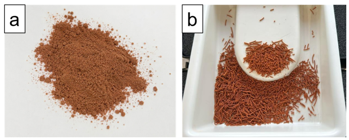
MIL-100(Fe) was synthesized via an upscaled, room-temperature green route adapted from Tan et al. [12], using all chemicals as received without further treatment. In a typical procedure, 8.58 g (40.8 mmol) of 1,3,5-benzenetricarboxylic acid (H3BTC, 98%, Thermo Scientific Chemicals, Waltham, MA, USA) was dissolved under vigorous stirring in 264 mL of an aqueous sodium hydroxide solution (NaOH, 98%, Sigma-Aldrich, St. Louis, MO, USA; 122.4 mmol). Separately, an iron(II) precursor solution was prepared by dissolving 17.02 g (61.2 mmol) of iron(II) sulfate heptahydrate (FeSO4·7H2O, 98%, Sigma-Aldrich) in 264 mL of superpure water for trace analysis (CARLO ERBA Reagents S.r.l., Cornaredo, Italy). The H3BTC solution was added dropwise to the iron(II) salt solution, and the resulting mixture was stirred for 24 h to allow for crystallization under ambient temperature. The progress of the reaction was visually marked by a gradual color change in the solution, from yellowish green to orange and finally dark brown, signaling the formation of MIL-100(Fe) crystals. The pH was recorded immediately after the complete addition of all reactants and monitored multiple times throughout the washing procedure. Finally, the orangish-brown powder (Figure 1a) was collected via filtration and washed sequentially with superpure water and ethanol (99.5%, Sigma-Aldrich) to neutralize the solution pH and completely remove any unreacted material. To provide the material quantity required for shaped body production, the synthesis was scaled up by a factor of 4. Specifically, 310 mmol of H3BTC (64.99 g), 930 mmol of NaOH (37.09 g), and 460 mmol of FeSO4·7H2O (128.91 g) were reacted in superpure water under the same ambient conditions. The resulting batch (113 g) was subsequently isolated, dried, and used for pelletization. Pelletization was performed using a Caleva Multi Lab Scientific extruder (Caleva Process Solutions Ltd., Dorset, UK), adding polyvinylpyrrolidone (PVP, molecular weight 1,300,000, Sigma Aldrich, Saint Louis, MO, USA) and water as solvent. PVP binder was added as a dry powder to maintain control over the total moisture content. The MOF:PVP mass ratio was set to 1:0.04, with water added to achieve a final wet mass water content of 48–50 wt%. Following extrusion, the pellets (Figure 1b) were dried in an oven at 308 K overnight and subsequently characterized and tested.

2.2. Material Characterization

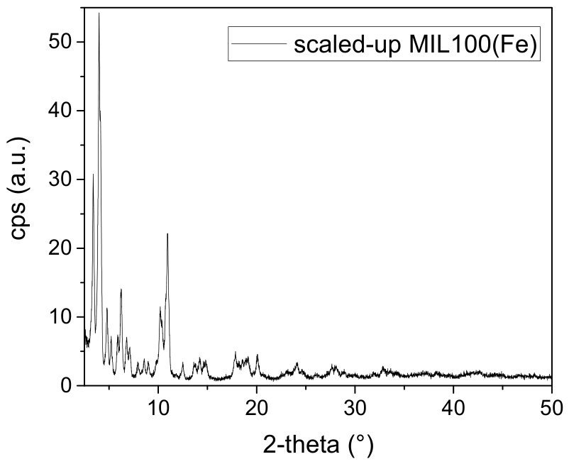
The crystalline structure of the scaled-up MIL-100(Fe) powder was analyzed via Powder X-ray Diffraction (PXRD) using a Bruker D8 ADVANCE diffractometer (Billerica, MA, USA) with Cu Kα radiation (lambda = 1.5406 Å), operating at 40 kV and 40 mA. The PXRD pattern was collected in the 2-theta range of 2–50° with a step size of 0.01° and a count time of 0.3 s per step. Figure 2 reports the X-ray diffraction (XRD) pattern of the scaled-up MIL-100(Fe). The material exhibits the characteristic diffraction peaks typical of the highly crystalline MIL-100(Fe) framework. Specifically, the low-angle region displays intense defining reflections below 7° at approximately 3.4°, 4.0°, 4.8°, 5.3°, 5.9°, and 6.3°, corresponding to the characteristic Miller indices of the MIL-100 topology. Secondary reflections are also clearly distinguishable at higher 2-theta angles, including the characteristic doublet/peak near 11°. Furthermore, no significant diffraction reflections related to impurities are observed, confirming the phase purity and successful synthesis of the scaled-up MOF structure.
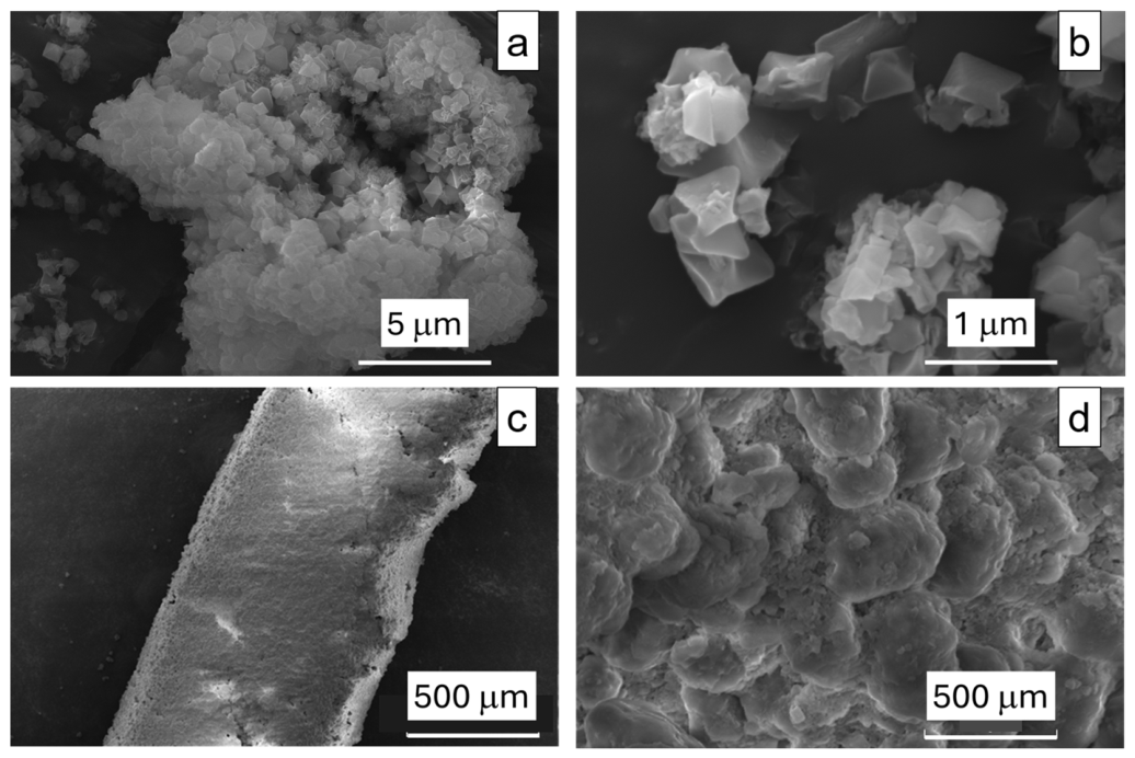
Particle morphology and crystal size were examined using a Field Emission Environmental Scanning Electron Microscope (FE-ESEM, FEI Quanta FEG 450, Hillsboro, OR, USA) at an accelerating voltage of 10 kV. Before imaging, samples were sputter-coated with a thin chromium layer to enhance electrical conductivity. Morphological characterization of the prepared pellets was similarly conducted via SEM.
The powder sample exhibits a characteristic polycrystalline aggregate structure (Figure 3a). At higher magnification (Figure 3b), the individual crystallites display well-defined octahedral geometry, which is typical for the MIL-100 framework, with crystal sizes ranging around 200–800 nm. Following the shaping process, the resulting pellets were characterized to assess their macroscopic structure. Figure 3c illustrates the profile of a pellet, highlighting a compact and coherent macrostructure. High-magnification surface analysis (Figure 3d) reveals a densely packed structure composed of consolidated grains with inter-granular macroporosity retained between the compacted domain boundaries, which is crucial for favoring mass transfer during sorption processes.
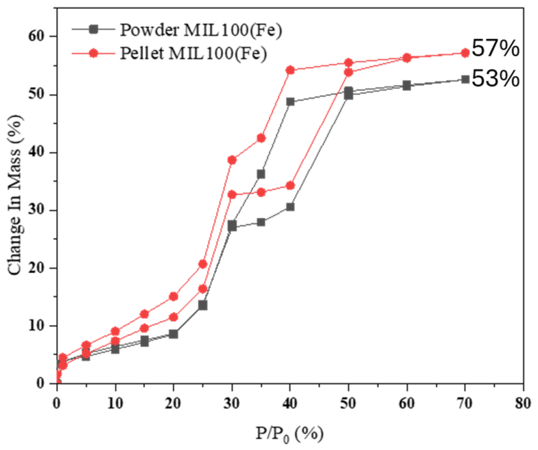
Water vapor sorption behavior of both powder and pellet samples was evaluated using a DVS Vacuum analyzer (Surface Measurement Systems, London, UK) integrated with a microbalance (resolution: 0.1 μg) within a temperature-controlled housing. Approximately 10 mg of sample was loaded and activated at 100 °C for 3 h under vacuum. Water sorption isotherms were obtained at 303 K across relative pressures (P/P0) up to 70%. The water uptake capacity was calculated using the equation wt.% = (m − m0)/m0, where m represents the equilibrium mass at (T, P/P0) and m0 corresponds to the initial dry sample mass. Data reproducibility was confirmed over three consecutive sorption–desorption cycles.
Figure 4 compares the water uptake of the pristine powder with that of the shaped pellet. Both samples display the characteristic S-shaped (type V) isotherm typical of MIL-100(Fe), featuring two distinct steps: the first sharp uptake around P/P0 = 25–30% (corresponding to the filling of the smaller mesoporous cages) and a second step around P/P0 = 40% (filling of the larger cages), followed by a plateau. Interestingly, the shaped pellet achieves a maximum water uptake of 57 wt.% at P/P0 = 70%, slightly higher than the 53 wt.% recorded for the parent powder. This suggests that the mechanical pelletization process does not induce structural collapse or pore blockage.

2.3. Heat Exchanger Selection and Preparation

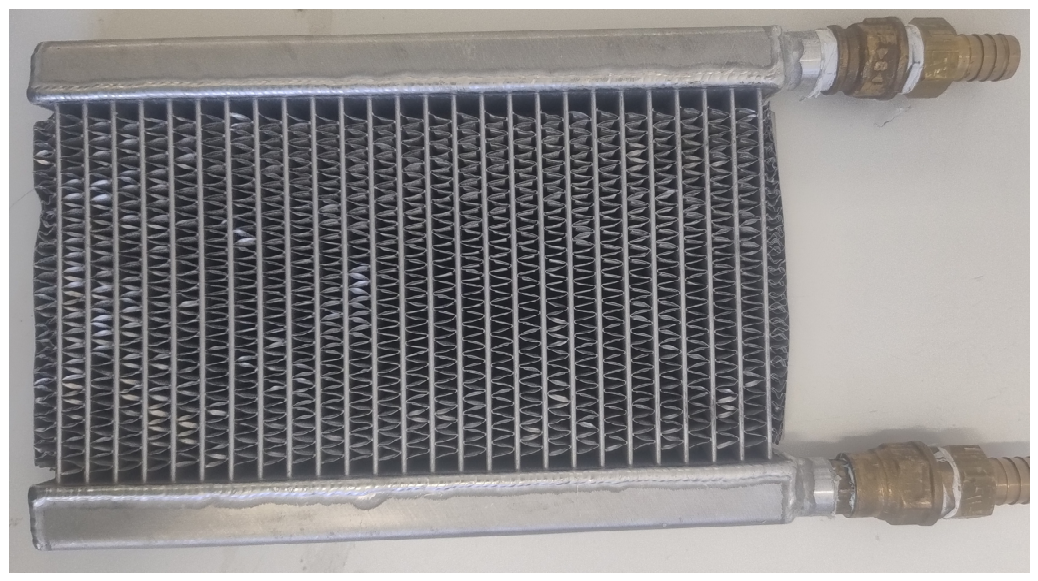
The selected heat exchanger (HEX) is an aluminum fin-and-flat-tube heat exchanger that has been widely used by the authors’ in earlier investigations, as reported in [13,14]. Its external dimensions are 170 × 257 × 27 mm, the metal mass is 0.636 kg, and the envelope volume is approximately 1.1 dm3. The heat-transfer area is 1.66 m2, corresponding to a surface-to-envelope-volume ratio of about 1.5 m2 dm−3. The tube pitch is 10 mm and the fin pitch is 2 mm. The specific heat exchanger was selected since it satisfies all the heuristic criteria identified for efficient operation in sorption-based systems that have been identified in [15]. The heat exchanger is shown in Figure 5.
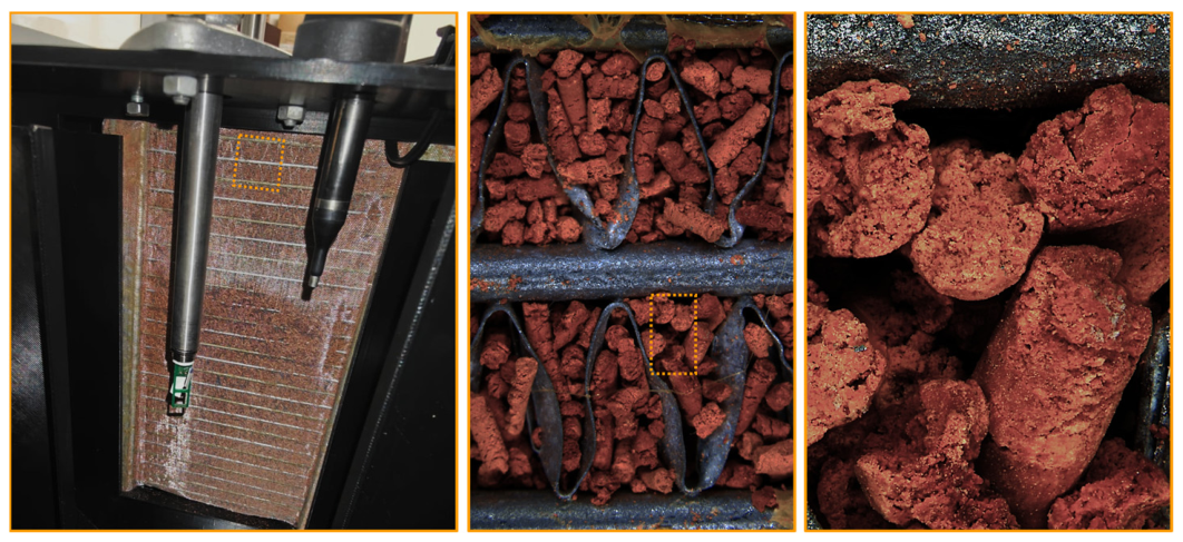
Loose MOF-100(Fe) particles were introduced into the spaces between fins and retained using a metallic mesh. The dry mass of adsorbent used is 130 g. A picture of the HEX is shown in Figure 6. The picture in the middle shows that the sorbent is well in contact with the metal of the fins and that the amount of material and material distribution in the various fins is comparable.

3. Operating Principle

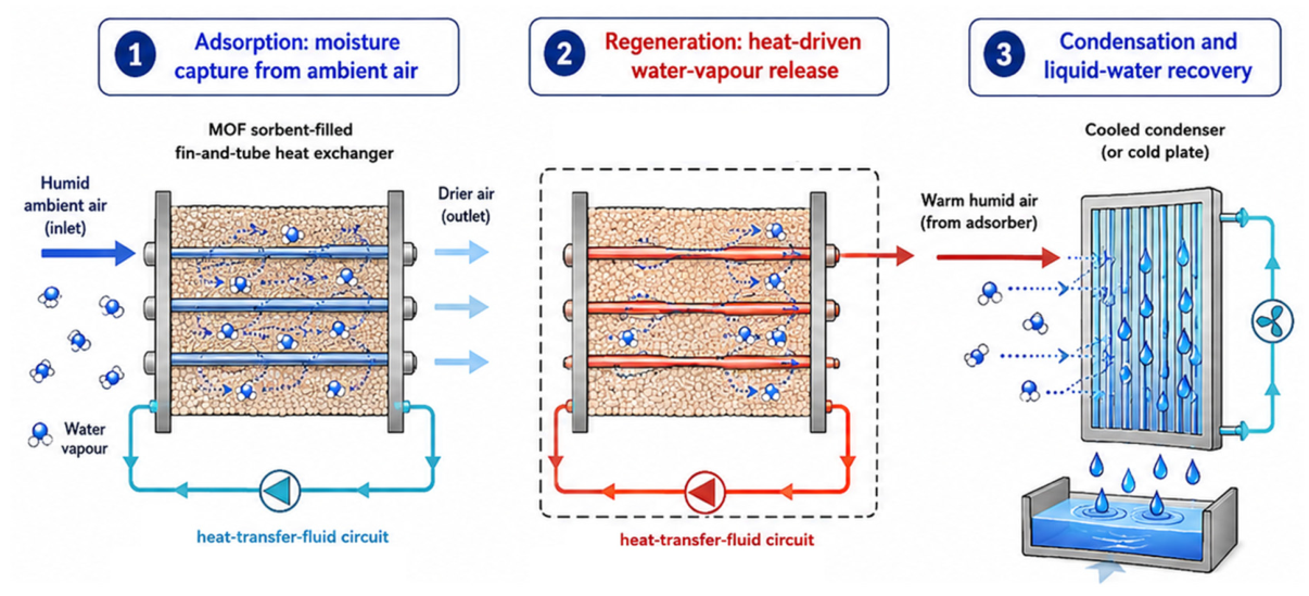
The investigated atmospheric water harvesting system operates through a cyclic adsorption–desorption process. During the adsorption phase, ambient air is forced through the heat exchanger containing the sorbent. Water vapor is removed from the air and retained within the porous material, while the heat released by adsorption is transferred to the circulating heat-transfer fluid. Cooling the sorbent during this stage helps maintain the vapor-pressure difference required for continued moisture uptake and limits the reduction in adsorption capacity caused by temperature rise.
Once the selected adsorption endpoint is reached, the system is isolated from the ambient environment and regeneration begins. A hot heat-transfer fluid is circulated through the heat exchanger, increasing the sorbent temperature and promoting the release of the previously adsorbed water. The resulting warm and humid air is circulated towards the condensation section, where it is cooled below its dew-point temperature. Water vapor consequently condenses on the cold surface and the resulting liquid is directed towards a collection reservoir. At the end of regeneration, the sorbent is cooled to the adsorption temperature and the system is reopened to ambient air. A new cycle is then started. The operating principle is illustrated in Figure 7.

4. Experimental

4.1. Testing Rig

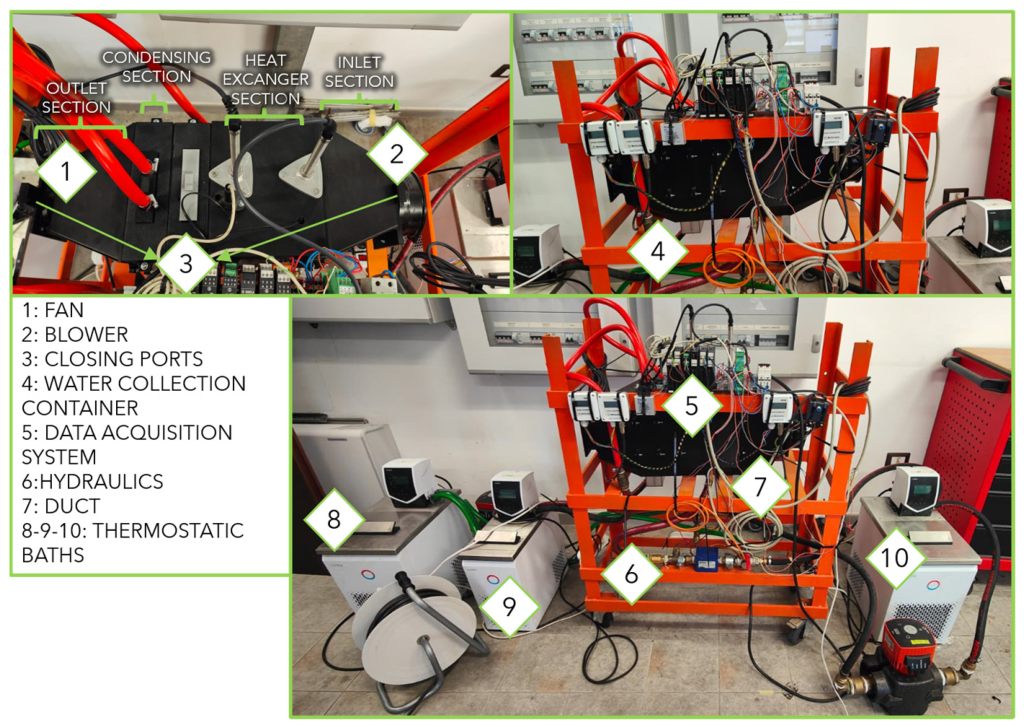
The heat exchanger was installed in a testing rig realized in-house at CNR. It consists of a modular duct manufactured by a fused filament using ABS. The inlet section contains an ebm-papst centrifugal blower with a nominal maximum flow rate of 230 m3 h−1 and a maximum pressure rise of 120 Pa, followed by a diffuser. The central test section constrains the air to pass through the adsorber and contains the upstream and downstream temperature, and relative-humidity and velocity measurement points. The heat exchanger is connected through valves to separate hot and cold thermostatic baths.
Downstream of the adsorber, a restricted opening leads to a condensation chamber containing a liquid-cooled cold plate positioned approximately normal to the flow. A SUNON MA axial fan with a nominal maximum flow of 68 m3 h−1 drives internal recirculation and exhaust. Manual ports located downstream of the inlet blower and downstream of the outlet fan allow the duct to be isolated during regeneration.
A picture of the testing rig is shown in Figure 8. It is worth mentioning that the inlet condition of the air stream is controlled using a custom-made humidifier. A test is considered valid if, within its entire duration, air temperature and relative humidity are stable within ±5% of the initial value.

4.2. Instrumentation and Data Acquisition

All signals are acquired using bus-connected Seneca input/output modules. A LabVIEW (2025Q2) routine records the measured variables, while water-vapor properties and air density are calculated from temperature, relative humidity and pressure using CoolProp (6.0.2) [16]. The sensor list and their specifications are summarized in Table 1. All the sensors used were calibrated from factory prior to the installation in the experimental testing rig. Data acquisition was carried out each second. All the sensors have a response time lower than the selected acquisition frequency. The sensors on the air inlet/outlet are placed in the middle of the inlet/outlet section, 2 cm away from the heat exchanger. The water temperature sensors are placed within 3 cm from the inlet/outlet manifolds of the heat exchanger.

4.3. Testing Procedure

The testing procedure is based on four steps:
  • Open-system pre-conditioning. The duct sections and condensation insert are arranged for through-flow operation. The blower and fan are operated until inlet and outlet temperature and humidity become stable.
  • Drying. The adsorber is connected to the hot bath with inlet and outlet ports open, without a connection to the cold plate and kept at high temperature for 2 h. This step is only done once per day as part of the pre-conditioning step, in order to have the system start from drying conditions.
  • Adsorption. The cold-bath valves are opened, and airflow is adjusted to the target velocity. Adsorption continues until the inlet–outlet humidity ratio difference falls below the selected endpoint, nominally 0.5 gwater kgdry-air−1, or until a predefined maximum duration is reached.
  • Desorption and condensation. The inlet and outlet ports are closed, the cold plate is inserted and the adsorber is connected to the hot bath. Internal air is circulated by the fan. The stage is stopped when the difference between inlet and outlet humidity ratio reaches 0.9 gwater kgdry-air−1.

4.4. Data Reduction and Kinetic Model

The main parameter evaluated is the instantaneous water adsorbed and desorbed:
w = m ˙ a i r ( ω i n − ω o u t ) m M O F
where w is the uptake in kg/kg, ω is the humidity ratio in kgwater/kgdryair, calculated from relative humidity and dry bulb temperature using CoolProp, and m ˙ a i r is the mass flow of air in kg/s, calculated as
m ˙ a i r = v   ρ   S f l o w
where v is the air velocity in m/s, ρ is the density of air in kg/m3, calculated from air temperature using CoolProp, and S f l o w is the area of the passage section for air, calculated from the drawings of the testing rig.
The cumulative uptake is normalized by the exact dry MOF mass and was calculated as
w ( t ) = 1 m M O F ∫ t = 0 t e n d m ˙ a i r ( ω i n − ω o u t ) d t
Extensive calculation of propagate uncertainty for the various experimental conditions was carried out using an online available tool [17] and values in the range 1.5–5% were calculated, thus indicating a good accuracy of the experimental setup.
Dynamic evaluation was carried out by fitting uptake evolution with time using a first-order approach:
w f i t ( t ) = w ∞ [ 1 − exp − t τ ]
where w ∞ [min] represents a fitting parameter. The characteristic time τ is the time needed to reach 63.2% of w∞. It correlates to the linear driving force approach commonly employed to describe sorption systems [18]:
d w d t = 1 τ ( w e q − w )
where weq represents the equilibrium uptake measured at a specific condition and therefore ( w e q − w ) represents the driving force for the process.
The fitting was carried out in Python 3.10 using the Scipy.optimize function (1.18.1). The initial guess value for the characteristic time is 70% of overall test time. A minimum R2 of 97% was accepted for the fitting.
It is important to mention that each experimental condition was repeated three times and the reported values in the following sections represent the average of the values. A test is only considered valid if the difference between the results of the different rounds is lower or equal to the experimental uncertainty.

5. Results

5.1. Typical Experimental Trends

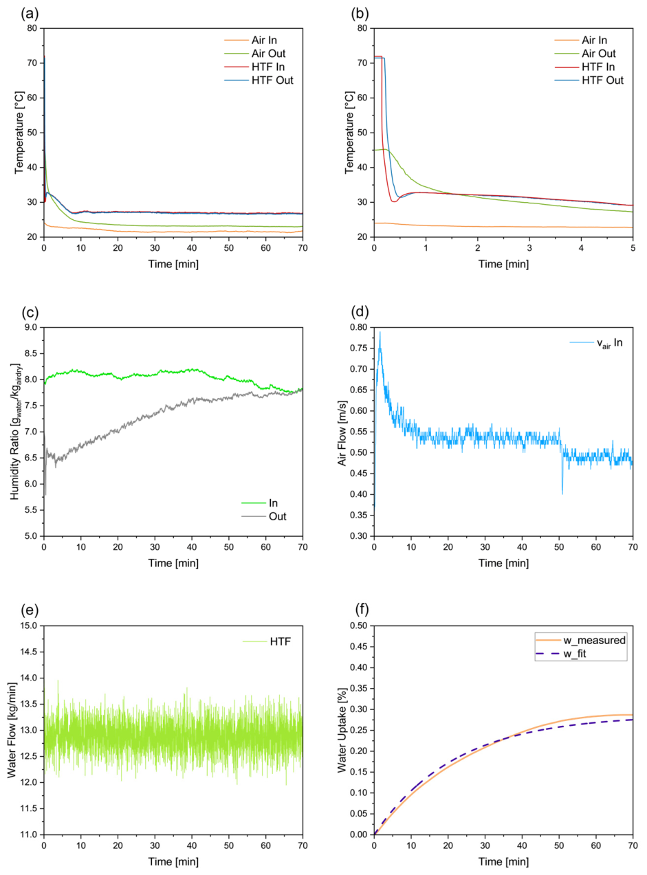
An example of typical experimental trends is shown in Figure 9. Figure 9a shows the heat transfer fluid and air temperatures. As it is possible to notice, the temperature jump realized allows reaching steady state adsorption temperature in approximately 10 min. For clarity, Figure 9b represents a zoom-in regarding the first 5 min of the process. Conversely, air temperature is constant throughout the adsorption process. Figure 9c shows the humidity ratio trend with time. It is possible to notice that the inlet and outlet value difference reduces over time, as the adsorption process progresses, until they reach equilibrium after approximately 1 h of test. Figure 9d and Figure 9e show the air velocity and heat transfer fluid flow rate, respectively. The HTF flow rate is constant throughout the entire process, whereas air velocity flow rate decreases at the very beginning of the process, due to the regulation of the fan, until the target value is reached. Finally, Figure 9f shows the cumulative water uptake measured, and the corresponding fitting with the exponential expression from Equation (4).

5.2. Effect of Desorption Temperature

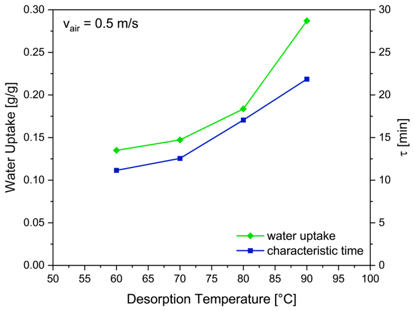
The effect of desorption temperature is shown in Figure 10. Values from 60 °C to 90 °C were evaluated. All the tests were done with an air velocity of 0.5 m/s, air inlet temperature of 20 °C and inlet RH% of 40%, corresponding to an inlet air humidity ratio of 5.8 gwater/kgair. The desorption temperature has both an effect on the overall water uptake, since the highest amount of water is processed, and on the characteristic time. This occurs because a higher desorption temperature allows for a higher driving force but, due to the higher amount of water being processed, the overall time needed is higher. Passing from 60 °C to 90 °C the uptake increases from 0.15 g/g to 0.28 g/g, whereas the characteristic increases with the same trend from 11 min to 22 min.
In order to better highlight the combined effect of desorption temperature on water production from both a thermodynamic and a dynamic point of view, the theoretical hourly water production for each case is reported in Figure 10 and Table 2. For the sake of calculation, an equal adsorption and desorption time was considered. The time needed for adsorption and desorption is considered as the time needed to reach 80% of overall conversion, corresponding to 1.6τ. As expected, 30–90 °C is the best condition, since it guarantees the highest water production rate. However, it is also possible to notice that the 30–60 °C condition allows an overall slightly higher hourly production than 30–70 °C and 30–80 °C, with a difference with the 30–90 °C cases in the range of 0.02 kgwater/kgsorbent. This indicates that, especially for small stand-alone systems, it is more profitable to reduce the desorption temperature and exploit ultra-low grade heat sources. The selection of the hourly water production as a means of comparison was done in order to balance the two concurrent effects that influence the value of τ: higher τ, under specific conditions, can be due to the higher amount of water adsorbed, whereas in some other cases (e.g., low air velocities), they can be due to intrinsic limitations of the heat exchanger. Therefore, all the results on hourly water production are meant to allow a clearer comparison of the actual water that can be produced in a certain condition in a realistic environment, considering both thermodynamic and dynamic effects. The values reported in Table 2 and in Table 3 in the following section are indicated as “theoretical maximum” since they are calculated considering the overall amount of water adsorbed and desorbed by the system, without considering the condensation efficiencies.

5.3. Effect of Adsorption Temperature

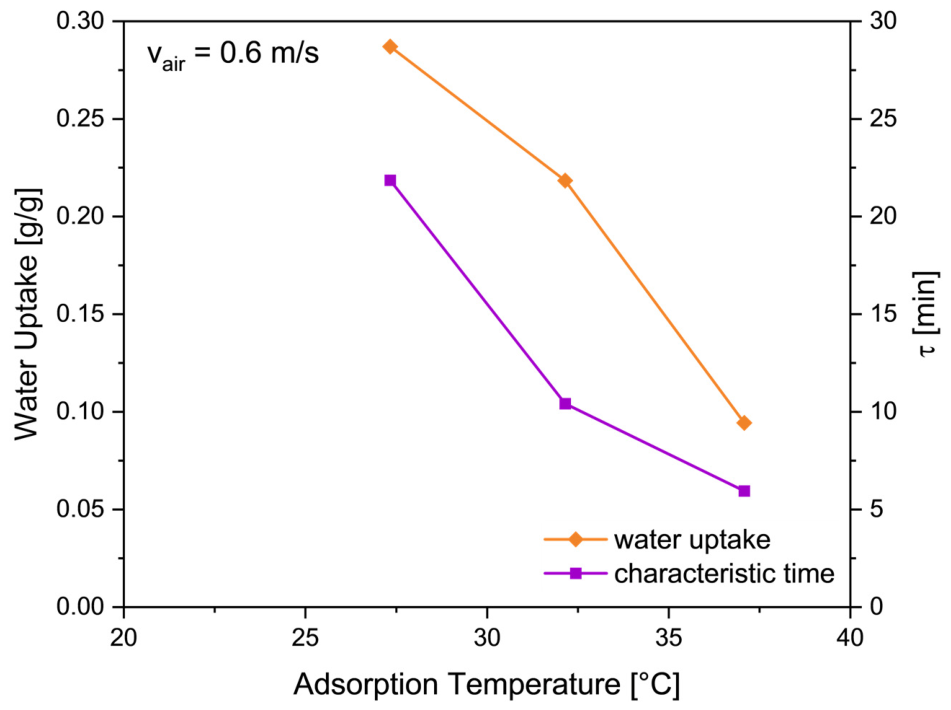
The effect of adsorption temperature is shown in Figure 11. Values from 27 °C to 37 °C were evaluated. All the tests were done with an air velocity of 0.6 m/s, desorption temperature of 70 °C and an inlet air humidity ratio of 7.5 gwater/kgair. As for the desorption temperature, the effect on both the overall water uptake and the dynamics of the process was evaluated. Increasing the adsorption temperature reduces the water processed, which, in turn, reduces the characteristic time. Passing from 27 °C to 37 °C, the uptake decreases from 0.27 g/g to 0.10 g/g, whereas the characteristic time goes from 21 min down to 6 min, thus indicating a fairly fast process. As for the previous case, the theoretical hourly water production was calculated and is presented in Table 3. Since, for MOFs, the dynamics is the limiting factor, the 27–70 °C case is actually the worst case in terms of hourly production. Indeed, since a higher water amount is processed, the time needed to complete the adsorption process is higher. On the other side, even though each cycle at 32–70 °C processes less water, the dynamics still allow a slightly higher water production. This means that the material is suitable for warmer climatic conditions, such as those typical of southern Europe or northern Africa.

5.4. Effect of Air Velocity

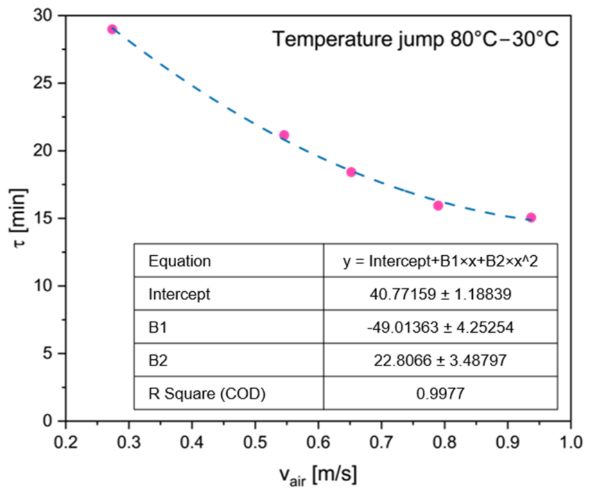
The effect of air velocity is shown in Figure 12. It influences the dynamics of the process and therefore the effect on characteristic time is evaluated. All the tests were done with a temperature jump to 80 °C to 30 °C and inlet humidity ratio of 7 gwater/kgair. Increasing the air velocity reduces the characteristic time with a quadratic trend, passing from 28 min at 0.27 m/s down to 15 min at 0.93 m/s. This effect is mostly due to the heat exchanger. Indeed, some of the authors of this study evaluated and reported the Nusselt–Reynolds correlation for the heat exchanger employed in this study in [14]. This also indicates that enhancing the productivity of the system requires optimization at different levels, i.e., also on the heat exchanger, beyond the sorbent itself.

6. Discussion

6.1. Energy Analysis

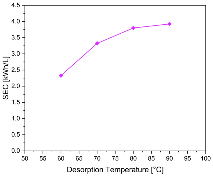
The goal of the energy analysis carried out was to evaluate the specific thermal energy consumption (SEC, kWh/L) for each cycle. It was calculated as the ratio between the energy provided for desorption and the processed water:
S E C = ∫ t = 0 t e n d m ˙ H T F c p ( T i n − T o u t ) ∆ w ∗ m a d s
The results are reported in Figure 13. As expected, the thermal energy required passes from 2.3 to 3.9 kWh/Lwater. The values reported are quite high, compared for instance to the values reported by some of the authors in [13]. This is mostly due to the low amount of sorbent compared to the mass of the heat exchanger, even in comparison with the work mentioned above. It is mostly due to the high specific volume of the MOFs, and therefore the low density, but it is also indicated that a specific activity is needed to improve the heat exchanger to be employed. It would indeed require a higher surface/volume ratio and a lower thermal mass. From a purely energetic point of view, operation at 60 °C appears the most favorable, since it is associated with a lower SEC. However, it is important to notice that low temperatures are associated with a lower productivity of the system, and therefore a higher size needed and, in turn, higher CAPEX. The SEC, as calculated according to Equation (6), does not take into account the energy consumption of auxiliaries (fans, pumps etc.). However, the preliminary techno-economic analysis carried out in Section 6.3 presents the operating costs considering also such contributions.

6.2. Mass Transfer Analysis

The characteristic time presented in Section 5 with varying operating conditions is strictly linked to heat and mass transfer limitations. In the sorbent examined for this study, moisture transport occurs through several sequential steps: convective transfer from the bulk airflow to the particle surface, diffusion across the void spaces between particles in the packed bed, diffusion into the hierarchical micro/mesoporous framework, and water uptake within the sorbent cages. As a result, the dynamic data obtained reflect an overall, bed-scale response rather than a simple molecular diffusion process.
Examining the influence of air velocity helps identify the rate-limiting step more clearly. At lower velocities, raising the flow rate markedly shortens the characteristic time, showing that gas-phase convective resistance plays a major role in limiting the process rate. However, for air velocities higher than 0.65 m/s, the reduction in characteristic time is less pronounced. This indicates that the external convective resistance is less pronounced. For the specific material selected, one of the explanations could be that the adsorption process becomes limited by sorbent internal diffusion. However, further small-scale investigations will be carried out to evaluate this aspect.
As indicated, in Section 4.4, Equation (5), the characteristic time represents the inverse of the mass-transfer time constant in a linear driving force model. Considering the higher air velocities, the results from Figure 12 indicate that the mass transfer constant is in the range of 0.057–0.067 min−1. These figures indicate that the fin-and-tube design achieves notably faster mass transfer than typical slow-cycling packed-bed systems, making it well-suited for repeated cycling.

6.3. Economic and Scalability Considerations

A full techno-economic evaluation is beyond the scope of this work, but the authors performed a preliminary cost estimate. Both CAPEX and OPEX depend heavily on the chosen mode of operation, namely grid-connected, which assumes access to external heat and cooling sources, versus off-grid, which requires dedicated heat and power supplies. The analysis carried out uses the assumptions already discussed by some of the authors in [13]:
  • 150 kg of MIL-100(Fe) sorbent, split between two reactors running in counter-phase to enable continuous operation.
  • OPEX limited to electricity consumption by the blowers, dry cooler, and fans.
  • CAPEX covering the sorbent material, metal components (piping and support structure), heat exchangers, dry cooler, and the pumps/blowers required for operation.
  • Component sizing extrapolated from calculations for a full-scale unit, based on an intermediate-scale prototype (20 kg sorbent) currently being tested.
  • Component pricing based on quotes obtained by the authors in spring 2025 in Italy.
  • Full cost breakdowns are listed in Table 4.
Under these assumptions, total OPEX is about 700 €, or roughly 0.5 c€ per liter of water produced. CAPEX is approximately 28,000 €, with the sorbent only accounting for approximately 16% of the total. This indicates that the limiting factor is not the sorbent itself, but the complexity of the system and the need for a bulky and efficient heat transfer, which is reflected in the high cost for aluminum flat-tube heat exchangers with high surface area.

7. Conclusions

This study investigated a sorption-based atmospheric water harvesting (AWH) system utilizing approximately 100 g of shaped MIL-100(Fe) integrated into an active aluminum fin-and-flat-tube heat exchanger. By using a controlled experimental setup, this work provided critical intermediate-scale insights into the coupled thermal and mass-transfer dynamics governing a packed-bed adsorber under realistic operating conditions and integrated into a flat-tube finned heat exchanger. The kinetic analysis revealed characteristic adsorption times ranging between 22.7 and 33 min, with air velocity identified as the primary governing factor. Gas-phase convective resistance dominated at lower flow rates, whereas internal sorbent diffusion became the rate-limiting step at velocities above 0.65 m/s. The resulting mass transfer rate constants (0.057–0.067 min−1) confirmed the suitability of the fin-and-tube architecture for rapid cyclic operation. Thermodynamically, raising the desorption temperature from 60 °C to 90 °C enhanced the total water uptake from 0.15 g/g to 0.28 g/g, accompanied by an increase in characteristic time from 11 to 22 min. Conversely, higher adsorption temperatures reduced equilibrium capacity while accelerating process dynamics, demonstrating the flexibility of the material for operation in warm climates and with ultra-low-grade heat sources. Specific energy consumption ranged from 2.3 to 3.9 kWh/L, reflecting the relatively high thermal inertia of the heat exchanger compared to the loaded MOF mass. Preliminary economic scaling for a 150 kg system yielded an estimated OPEX of 0.5 c€ per liter of water, with the sorbent accounting for only 16% of the overall CAPEX. These findings demonstrate that proper design of the heat exchanger can overcome the dynamic issues of the material and that, under multi-cyclic daily operation, MOFs can compete with other materials, such as nanostructured systems and hydrogels. Further activities to even improve the economic feasibility of the proposed system include the design, manufacturing and testing of low-cost and high-surface-area heat exchangers that will reduce the characteristic time for the adsorption/desorption process.

Author Contributions

Conceptualization, E.P. and V.P.; methodology, A.F., R.D.P., R.D.S. and D.L.R.; validation, V.B., E.P. and V.P.; formal analysis, A.F. and D.L.R.; investigation, A.F., R.D.P. and R.D.S.; resources, E.P.; data curation, A.F. and V.P.; writing—original draft preparation, A.F., V.B., E.P. and V.P.; writing—review and editing, V.B., E.P. and V.P.; supervision, E.P. and V.P.; project administration, E.P.; funding acquisition, E.P. All authors have read and agreed to the published version of the manuscript.

Funding

This research was funded by European Union-Next Generation EU, Mission 4 Component 2, Investment 1.1-Call Prin 2022 PNRR-Directorial Decree n. 1409 of 14-09-2022, Project: INSTINCT-INnovative Sorbent maTerIals and techNologies for low-Carbon heating and waTer provision. CUP: J53D23015690001–ID code: PRIN_2022PNRR_P2022CRXAM_001.

Data Availability Statement

The original contributions presented in this study are included in the article. Further inquiries can be directed to the corresponding author.

Acknowledgments

During the preparation of this manuscript, the authors used ChatGPT 5.5 for the purposes of improving the text’s grammar and ChatGPT 5.6 for the creation of Figure 8. The authors have reviewed and edited the output and take full responsibility for the content of this publication.

Conflicts of Interest

The authors declare no conflicts of interest.

Abbreviations

DVSDynamic vapor sorption
HTFHeat transfer fluid
MOF Metal–organic framework
RHRelative humidity, %
SECSpecific energy consumption, kWh/L
SEMScanning electron microscopy
XRDX-ray diffraction
mMass, kg
m ˙ Mass flow rate, kg/s
SSurface, m2
tTime, min
TTemperature, °C
vVelocity, m/s
wUptake, kg/kg
ωHumidity ratio, g/kg
ρDensity, kg/m3
τCharacteristic time, s
Subscription
adsAdsorption
desDesorption
eqEquilibrium
inInlet
outOutlet

References

  1. Yang, K.; Pan, T.; Lei, Q.; Dong, X.; Cheng, Q.; Han, Y. A Roadmap to Sorption-Based Atmospheric Water Harvesting: From Molecular Sorption Mechanism to Sorbent Design and System Optimization. Environ. Sci. Technol. 2021, 55, 6542–6560. [Google Scholar] [CrossRef] [Scilit] [PubMed]
  2. Zhong, Y.; Zhang, L.; Li, X.; El Fil, B.; Díaz-Marín, C.D.; Li, A.C.; Liu, X.; LaPotin, A.; Wang, E.N. Bridging Materials Innovations to Sorption-Based Atmospheric Water Harvesting Devices. Nat. Rev. Mater. 2024, 9, 681–698. [Google Scholar] [CrossRef] [Scilit]
  3. Silva, M.P.; Ribeiro, A.M.; Silva, C.G.; Cho, K.H.; Lee, U.H.; Faria, J.L.; Loureiro, J.M.; Chang, J.S.; Rodrigues, A.E.; Ferreira, A. Atmospheric Water Harvesting on MIL-100(Fe) Upon a Cyclic Adsorption Process. Sep. Purif. Technol. 2022, 290, 120803. [Google Scholar] [CrossRef] [Scilit]
  4. Jeremias, F.; Khutia, A.; Henninger, S.K.; Janiak, C. MIL-100(Al, Fe) as Water Adsorbents for Heat Transformation Purposes—A Promising Application. J. Mater. Chem. 2012, 22, 10148–10151. [Google Scholar] [CrossRef] [Scilit]
  5. Idrees, M.; Mastronardo, E.; Piperopoulos, E.; Milone, C.; Calabrese, L. Impact of HF-Free Synthesis Modification on Purity and Adsorption Performances of MOF MIL-100(Fe) for Gas Capture and Energy Storage Applications. Appl. Sci. 2025, 15, 6097. [Google Scholar] [CrossRef] [Scilit]
  6. Almassad, H.A.; Abaza, R.I.; Siwwan, L.; Al-Maythalony, B.; Cordova, K.E. Environmentally Adaptive MOF-Based Device Enables Continuous Self-Optimizing Atmospheric Water Harvesting. Nat. Commun. 2022, 13, 4873. [Google Scholar] [CrossRef] [Scilit] [PubMed]
  7. Song, W.; Zheng, Z.; Alawadhi, A.H.; Yaghi, O.M. MOF Water Harvester Produces Water from Death Valley Desert Air in Ambient Sunlight. Nat. Water 2023, 1, 626–634. [Google Scholar] [CrossRef] [Scilit]
  8. Feng, Y.; Ge, L.; Zhao, Y.; Li, Q.; Wang, R.; Ge, T. Active MOF Water Harvester with Extraordinary Productivity Enabled by Cooling-Enhanced Sorption. Energy Environ. Sci. 2024, 17, 1083–1094. [Google Scholar] [CrossRef] [Scilit]
  9. Ortiz, N.P.; Rao, S.R. Compact Rapid Cycling Fuel-Fired Atmospheric Water Harvesting Device for All-Day Water Production. Cell Rep. Phys. Sci. 2024, 5, 102115. [Google Scholar] [CrossRef] [Scilit]
  10. Li, Q.; Ying, Y.; Tao, Y.; Li, H. Assemblable Carbon Fiber/Metal–Organic Framework Monoliths for Energy-Efficient Atmospheric Water Harvesting. Ind. Eng. Chem. Res. 2022, 61, 1344–1354. [Google Scholar] [CrossRef] [Scilit]
  11. Wu, Q.; Su, W.; Li, Q.; Tao, Y.; Li, H. Enabling Continuous and Improved Solar-Driven Atmospheric Water Harvesting with Ti3C2-Incorporated Metal–Organic Framework Monoliths. ACS Appl. Mater. Interfaces 2021, 13, 38906–38915. [Google Scholar] [CrossRef] [Scilit] [PubMed]
  12. Tan, K.L.; Foo, K.Y. Preparation of MIL-100 via a Novel Water-Based Heatless Synthesis Technique for the Effective Remediation of Phenoxyacetic Acid-Based Pesticide. J. Environ. Chem. Eng. 2021, 9, 104923. [Google Scholar] [CrossRef] [Scilit]
  13. Palomba, V.; Fotia, A.; De Salvo, R.; Chairi, M.; Brancato, V.; Frazzica, A. Experimental Investigation of a Sorption-Based Atmospheric Water Harvesting System Using a LiCl/CaCl2–Silica Gel Composite. J. Water Process Eng. 2026, 91, 110566. [Google Scholar] [CrossRef] [Scilit]
  14. Palomba, V.; Fotia, A.; Costa, F.; La Rosa, D.; Brancato, V. Experimental Testing of a Heat Exchanger with Composite Material for Deep Dehumidification. Energies 2025, 18, 2418. [Google Scholar] [CrossRef] [Scilit]
  15. Grekova, A.; Tokarev, M. An Optimal Plate Fin Heat Exchanger for Adsorption Chilling: Theoretical Consideration. Int. J. Thermofluids 2022, 16, 100221. [Google Scholar] [CrossRef] [Scilit]
  16. Bell, I.H.; Wronski, J.; Quoilin, S.; Lemort, V. Pure and Pseudo-Pure Fluid Thermophysical Property Evaluation and the Open-Source Thermophysical Property Library CoolProp. Ind. Eng. Chem. Res. 2014, 53, 2498. [Google Scholar] [CrossRef] [Scilit] [PubMed]
  17. Uncertainty Calculator. Available online: https://uncertaintycalculator.com/ (accessed on 28 August 2026).
  18. Sapienza, A.; Velte, A.; Girnik, I.; Frazzica, A.; Füldner, G.; Schnabel, L.; Aristov, Y. “Water—Silica Siogel” Working Pair for Adsorption Chillers: Adsorption Equilibrium and Dynamics. Renew. Energy 2017, 110, 40–46. [Google Scholar] [CrossRef] [Scilit]
  19. Severino, M.I.; Freitas, C.; Pimenta, V.; Nouar, F.; Pinto, M.L.; Serre, C. Cost Estimation of the Production of MIL-100(Fe) at Industrial Scale from Two Upscaled Sustainable Synthesis Routes. Ind. Eng. Chem. Res. 2025, 64, 2708–2718. [Google Scholar] [CrossRef] [Scilit] [PubMed]
Figure 1. Synthesized MIL-100(Fe): (a) as-synthesized powder and (b) pellets obtained after the shaping process.
Energies 19 04302 g001
Figure 2. X-ray diffraction patterns of scaled-up MIL100(Fe).
Energies 19 04302 g002
Figure 3. SEM micrographs of the synthesized MIL-100(Fe) material in different forms: (a,b) as-synthesized powder at low and high magnifications; (c,d) cross-section and surface morphology of the shaped pellets at low and high magnifications.
Energies 19 04302 g003
Figure 4. Dynamic vapor sorption (DVS) water isotherms at 303 K. Comparison of water sorption–desorption isotherms between the Powder MIL-100(Fe) and Pellet MIL-100(Fe).
Energies 19 04302 g004
Figure 5. The selected heat exchanger.
Energies 19 04302 g005
Figure 6. Picture of the tested MOF inside the heat exchanger. The orange boxes are shown at higher magnification.
Energies 19 04302 g006
Figure 7. Operating principle. Image generated using ChatGPT 5.6 Sol.
Energies 19 04302 g007
Figure 8. Test rig scheme. Adapted from [13] with permission.
Energies 19 04302 g008
Figure 9. Example of experimental trends: (a) heat transfer fluid and air temperature profiles; (b) temperature profiles zoom-in regarding the first 5 min of the process; (c) humidity ratio trend with time; (d) air velocity profile; (e) heat transfer fluid flow rate; (f) cumulative water uptake measured and fitted.
Energies 19 04302 g009
Figure 10. Effect of desorption temperature.
Energies 19 04302 g010
Figure 11. Effect of adsorption temperature.
Energies 19 04302 g011
Figure 12. Effect of air velocity.
Energies 19 04302 g012
Figure 13. Specific energy consumption as a function of desorption temperature.
Energies 19 04302 g013
Table 1. Sensors and their accuracy.
Measuring PointVariableSensorAccuracy
Inlet and outlet airTemperaturePt100 Class A; Delta Strumenti HD4817ETC2.5 (Delta Strumenti, Italy)±0.3 °C
Inlet and outlet airRelative humidityThermoset-polymer capacitive sensor; Delta Strumenti HD4817ETC2.5 (Delta Strumenti, Italy)±1.5% RH
Inlet air streamAir velocitySchmidt SS 20.260 hot-wire anemometer (Schmidt, Italy)±5% of reading
Hot and cold liquid circuitsTemperatureClass A type-T thermocouples; TC Direct (TC Direct, Italy)±0.2 °C
Liquid return circuitVolumetric flow rateMagFlow MVM-60 PA; 0.5–60 L min−1 (Bronkhorst, Precision Fluid Controls, Italy)±2.5% full scale
Table 2. Theoretical hourly water production with varying desorption temperature.
Operating Condition (Tads-Tdes)Theoretical Maximum Hourly Water Production
30–60 °C0.16 kgwater/kgsorbent
30–70 °C0.13 kgwater/kgsorbent
30–80 °C0.12 kgwater/kgsorbent
30–90 °C0.14 kgwater/kgsorbent
Table 3. Theoretical hourly water production with varying adsorption temperature.
Operating Condition (Tads-Tdes)Theoretical Hourly Water Production
27–70 °C0.16 kgwater/kgsorbent
30–70 °C0.26 kgwater/kgsorbent
32–70 °C0.27 kgwater/kgsorbent
Table 4. Cost breakdown for a 150 kg unit.
ComponentUnit Cost **Quantity *Overall Cost
MIL-100 (Fe)30 € [19]1504500 €
Blowers—needed flow: 4500 m3/h200 €2400 €
Pumps—needed flow: 12 m3/h2200 €24400 €
Heat exchangers—finned flat tube, required heat transfer area: 350 m24500 €29000 €
Dry cooler—required thermal energy: 250 kW7000 €17000 €
Pipes DN3006 €/m30180 €
Metallic structures20% of pipes + HEX cost11600 €
Electricity cost0.25 €/kWh2800 kWh700 €
* For full-scale system with 150 kg of sorbent. ** All quotation data will be available on request.
Disclaimer/Publisher’s Note: The statements, opinions and data contained in all publications are solely those of the individual author(s) and contributor(s) and not of MDPI and/or the editor(s). MDPI and/or the editor(s) disclaim responsibility for any injury to people or property resulting from any ideas, methods, instructions or products referred to in the content.