Article

Series-Connected Grid-Following and Grid-Forming Hybrid Control Strategy for VSC-HVDC Converters to Enhance Transient Voltage Stability in Receiving-End Power Grids


1
Electric Power Dispatching Control Center of Guangdong Grid Co., Ltd., Guangzhou 510000, China
2
Department of Electrical Engineering, Tsinghua University, Beijing 100084, China
*
Author to whom correspondence should be addressed.
Energies 2026, 19(17), 4219; https://doi.org/10.3390/en19174219
Submission received: 3 July 2026 / Revised: 23 August 2026 / Accepted: 2 September 2026 / Published: 7 September 2026
(This article belongs to the Section F1: Electrical Power System)

Abstract

With an increase in the High-Voltage Direct Current (HVDC) infeed, the strength of the receiving-end AC grid decreases, leading to transient voltage instability. Voltage source converter (VSC)-HVDC stations have a large unit capacity and high controllability, offering great potential for voltage support of the receiving-end grid. A grid-following/grid-forming (GFL–GFM) hybrid control can improve the oscillation stability of VSC stations under both strong and weak grid conditions; however, most relevant studies have focused on oscillation stability, while little attention has been paid to transient voltage regulation performance. Moreover, a quantitative analysis method for the transient active- and reactive-power characteristics of the hybrid control is lacking. This paper proposes a series-connected GFL/GFM hybrid control strategy along with a quantitative dynamic power analysis method. By establishing the closed-loop transfer function model, the steady-state power control performance and transient reactive-power response of the proposed control are quantitatively analyzed. Electro-Magnetic Transient (EMT) simulation results verify that, compared with the existing hybrid synchronization-type control, the proposed series-connected scheme exhibits superior performance in mitigating transient low-voltage and overvoltage issues, with the minimum voltage dip improved from 0.3 p. u. to 0.8 p. u. and the maximum overvoltage after fault clearance decreasing from 1.38 p. u. to 1 p. u.

1. Introduction

Ultra-high-voltage direct current (UHVDC) transmission serves as a backbone for interconnecting energy resources across China. Receiving-end systems, including Guangdong, Hong Kong, and Macau, consequently face high renewable penetration and multiple HVDC infeeds, making voltage stability a pressing concern [1,2]. Among the available solutions, VSC-HVDC has gained considerable momentum, as it eliminates the commutation failure risk inherent in Line-Commutated Converter (LCC)-HVDC systems [3].
Receiving-end converters in VSC-HVDC systems are predominantly GFL-controlled, relying on a Phase-Locked Loop (PLL) for grid synchronization and decoupled dq current loops for DC voltage and reactive-power regulation. Yet, as controlled current sources, GFL converters provide no inherent voltage or frequency support to the receiving-end grid, and they are particularly vulnerable to oscillatory instability under low short-circuit ratio (SCR) conditions [4].
GFM control offers an effective solution to weak-grid conditions. In [5], a virtual synchronous generator (VSG) control is applied to the receiving-end converter, while a VSG-based scheme with an outer DC voltage loop is used at the sending end. Alternative approaches have employed DC voltage synchronization control for converters at both ends [6]. Nevertheless, GFM strategies, including VSGs, are prone to oscillatory instability in strong grids [7]. To address varying grid strength, recent studies have proposed hybrid control schemes that combine GFL and GFM advantages. One representative method is the synchronization-type hybrid control, which fuses the PLL angle and the GFM-generated angle via weighted averaging [8,9,10,11] (hereafter termed synchronization-type hybrid control). However, Ref. [9] has argued that a fixed weighting ratio cannot adapt to grid strength variations and may still cause oscillations; accordingly, an adaptive scheme has been proposed.
Another category is GFM–GFL parallel control. In [12], the sum of the voltage references generated by GFL and GFM controls is used as the pulse width modulation (PWM) reference voltage. It is shown that a single converter can be equivalently represented as a GFM unit and a GFL unit connected in parallel via virtual impedances. By adjusting the virtual impedance, the relative contributions of each mode can be varied, thereby enhancing oscillation stability. However, the insertion of virtual impedance may degrade the converter’s support performance to the grid [8].
A third typical hybrid approach is GFL–GFM switching control, which selects the operating mode based on online or offline SCR measurements to ensure satisfactory oscillation stability in weak grids [13,14,15]. However, SCR measurements are not always reliable, and mode switching can cause transient current surges that deteriorate power quality. Although seamless switching techniques [16] can mitigate such surges, they tend to slow the power support response, which is detrimental to fast voltage regulation.
Most existing studies on hybrid control schemes have focused primarily on oscillation characteristics under strong or weak grids, highlighting the advantages of hybrid controls in improving oscillation stability. However, quantitative analyses of transient voltage regulation capabilities and active/reactive-power dynamic performances during faults remain limited.
In the synchronization-type hybrid control, reactive power is oriented via the synchronization loop, with the reactive current regulated to track its reference. The reactive-power dynamics are thus inherently constrained by PLL phase accuracy during transients. Under grid faults, the accompanying phase-angle jump [17] introduces a PLL phase error, shifting the converter current ahead of the grid voltage. This phase deviation causes unwanted reactive-power absorption, further degrading the voltage. Conversely, a leading phase-angle jump during voltage recovery [17] may lag the converter current behind the grid voltage, resulting in an excessive reactive-power injection that aggravates the transient overvoltage.
Regarding the GFM–GFL parallel control, as discussed earlier, adjusting the virtual impedance to alter the GFL/GFM ratio compromises the responsiveness of reactive-power support [8]. As for the GFL–GFM switching control, improper switching not only risks transient overcurrent but also makes the fast reactive support heavily dependent on the switching speed, the reliability of which remains to be verified.
This paper proposes a series-connected GFL–GFM hybrid control strategy, along with a quantitative analytical framework for power dynamics. The main contributions are as follows:
(1)
A series-connected GFL–GFM hybrid control method is proposed, which preserves the steady-state performance of the GFL control and the transient voltage-support capability of the GFM control. Compared with the existing hybrid synchronization-type control, the proposed series-connected scheme exhibits superior performance in mitigating transient low-voltage and overvoltage issues.
(2)
A closed-loop transfer function model for the grid-connected converter system under the proposed series-connected hybrid control is derived. Based on magnitude–frequency response analysis, it is shown that under steady-state conditions, the power dynamics are dominated by the GFL loop, which preserves the fast power response characteristic of GFL controls. The rise time of the system is lower than 0.2 s, which is faster than traditional GFM controls in weak grids.
(3)
A time-division control logic is established, characterized by “GFL dominance in steady states and GFM dominance during transients.” The derived transfer function model further demonstrates that, during transients, the power dynamics are governed by the GFM loop, thereby enabling the converter to provide reactive-power support. Compared with the conventional synchronization-based hybrid control, the proposed series-connected hybrid control outperforms in its transient voltage support under weak-grid conditions, improving voltage nadir and overvoltage magnitudes issues.
The rest of this paper is organized as follows. Section 2 presents the control structure of the proposed series-connected GFL–GFM hybrid control. Section 3 elaborates the steady-state and transient dynamic responses and voltage-support capabilities of the series-connected hybrid control. Section 4 provides case studies of voltage-support performances between the series-connected hybrid control and conventional synchronization-type hybrid controls.

2. Series-Connected GFL–GFM Hybrid Control

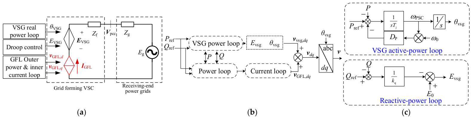
The proposed series-connected GFL–GFM hybrid control strategy is illustrated by the equivalent circuit of the VSC-HVDC grid-connected system, as shown in Figure 1a. In this scheme, θVSG and Evsg are generated by the VSG active-power control loop and the droop control, respectively. The voltage reference vGFL, dq is produced by the dq-axis power outer loop and current inner loop, with a control structure identical to that of conventional GFL controls except for the PLL. The dq-axis currents are oriented by θVSG, replacing the phase angle generated by the conventional PLLs. Zf denotes the filter impedance, and Vpcc is the voltage at the point of common coupling (PCC). The final PWM reference voltage is obtained by summing vvsg, dq and vGFL, dq, as depicted in Figure 1b, where vvsg, dq are obtained by the VSG power loop shown in Figure 1c.
The converter can thus be equivalently represented as a series connection of a grid-forming source and a grid-following source. Its power control principles and dynamic characteristics are analyzed in Section 3 as follows.

3. Analysis of Steady-State and Transient Dynamic Responses and Voltage-Support Capabilities of the Series-Connected Hybrid Control

3.1. Closed-Loop Transfer Function Model and Dynamic Characteristics Analysis

3.1.1. Closed-Loop Transfer Function Model

To quantitatively characterize the power control performance of the proposed series-connected hybrid control, it is essential to establish the closed-loop transfer function model of the power loop and examine its tracking capability using Bode plots.
As shown in Figure 1b, the VSG and GFL controls share the same active- and reactive-power references. The GFL loop is oriented by the phase-angle output from the VSG active-power loop. The linearized relationship between the converter output power variations (ΔP, ΔQ) and the reference variations (ΔPref, ΔQref) is given in (13), which is derived as follows.
Since the hybrid control structure in Figure 1b is implemented in the dq frame and oriented by the VSG power angle, the PCC voltage projections in this frame are expressed as:
v pcc , d = V pcc cos θ v θ vsg v pcc , q = V pcc sin θ v θ vsg
where Vpcc and θv are the magnitude and phase-angle of the PCC voltage, and θvsg is the phase-angle output from the VSG active-power loop. The linearized form of (1) is given in (2).
Δ v pcc , d Δ v pcc , q = V pcc 0 sin θ v 0 θ vsg 0 V pcc 0 sin θ v 0 θ vsg 0 cos θ v 0 θ vsg 0 V pcc 0 cos θ v 0 θ vsg 0 V pcc 0 cos θ v 0 θ vsg 0 sin θ v 0 θ vsg 0 Δ θ v Δ θ vsg Δ V pcc
According to the power transfer equation, the variation in Δθv induces an active-power disturbance at the converter output:
Δ P = E inv V pcc X f Δ θ v = k vsg Δ θ v
where Einv and Vpcc are the steady-state voltages at the converter terminal and PCC, respectively, while Xf is the filter reactance at the converter terminal. From the VSG active-power loop, the phase-angle deviation is expressed as:
Δ θ vsg = 1 J ω ref s + k p s Δ P ref Δ P = H θ P s Δ P ref Δ P
Combining (1)–(4), (2) can be simplified to (5), where θv0θvsg0 is the steady-state phase-angle difference between the PCC voltage and the VSG output angle. Under steady-state conditions, this difference is zero, as explained in Section 3.2. Vpcc0 denotes the steady-state PCC voltage magnitude. Furthermore, the power outer loop and current inner loop can be linearized as (6) and (7), respectively, where Kp and Ki are the PI control coefficients of the power loop, while kp and ki are those of the current loop.
Δ v pcc , d Δ v pcc , q = V pcc 0 sin θ v 0 θ vsg 0 V pcc 0 sin θ v 0 θ vsg 0 H θ P s k vsg cos θ v 0 θ vsg 0 V pcc 0 cos θ v 0 θ vsg 0 + V pcc 0 cos θ v 0 θ vsg 0 H θ P s k vsg sin θ v 0 θ vsg 0 Δ θ v Δ V pcc = H e Δ θ v Δ V pcc
Δ i dref Δ i qref = K p s + K i s 0 0 K p s + K i s P I PC Δ P ref Δ P Δ Q ref Δ Q
Δ v GFL , d = Δ v pcc , d ω PSC L f Δ i q k p s + k i s Δ i d ref Δ i d Δ v GFL , q = Δ v pcc , q + ω PSC L f Δ i d k p s + k i s Δ i q ref Δ i q
The linearized active and reactive power flowing through the PCC are given by:
Δ P Δ Q = 3 2 i d 0 i q 0 i q 0 i d 0 Δ v pcc , d Δ v pcc , q + 3 2 v pcc , d 0 v pcc , q 0 v pcc , q 0 v pcc , d 0 Δ i d Δ i q = 3 2 i d q 0 Δ v pcc , d Δ v pcc , q + v pcc , d q 0 Δ i d Δ i q
where Δvpcc,d, Δvpcc,q, Δid, and Δiq satisfy the relationship:
Δ v pcc , d Δ v pcc , q = s L g + r g ω 0 L g ω 0 L g s L g + r g Δ i d Δ i q + Δ E g d Δ E g q = s L g + r g ω 0 L g ω 0 L g s L g + r g Δ i d Δ i q = Z g Δ i d Δ i q
where ΔEgd and ΔEgq = 0 are the grid-side voltage variations, which are assumed constant. Combining (8), (9), and (5) yields:
Δ P Δ Q = 3 2 i d q Z g + v pcc , d q Z g 1 H e Δ θ v Δ V pcc = H P θ H P V H Q θ H Q V Δ θ v Δ V pcc
The relationship between the converter terminal voltage and the current is:
Δ v GFL , d Δ v GFL , q = s L g + L f + r g ω 0 L g + L f ω 0 L g + L f s L g + L f + r g Δ i d Δ i q = Z Δ i d Δ i q
By combining the outer power loop shown in (6); the inner current loop shown in (7); and the relationship between the PCC voltage and the power flow dynamics shown in (5), (10), and (12), we obtain the closed-loop transfer function model of the GFL power control as expressed by (13), where ρGFL denotes the GFL closed-loop transfer function.
Δ θ v Δ V pcc = H e 1 Z g Z P I aug _ VCC 1 P I VCC P I PC I 2 × 2 H e 1 Z g Z P I aug _ VCC 1 H e Δ P ref Δ P Δ Q ref Δ Q = H θ P ( s ) H θ Q ( s ) H V P ( s ) H V Q ( s ) Δ P ref Δ P Δ Q ref Δ Q
Δ P Δ Q = H P θ H P V H Q θ H Q V H θ P ( s ) H θ Q ( s ) H V P ( s ) H V Q ( s ) I 2 × 2 + H P θ H P V H Q θ H Q V H θ P ( s ) H θ Q ( s ) H V P ( s ) H V Q ( s ) Δ P ref Δ Q ref = ρ 11 _ GFL ( s ) ρ 12 _ GFL ( s ) ρ 21 _ GFL ( s ) ρ 22 _ GFL ( s ) ρ GFL Δ P ref Δ Q ref

3.1.2. Power Dynamic Characteristics of the Series-Connected Hybrid Control

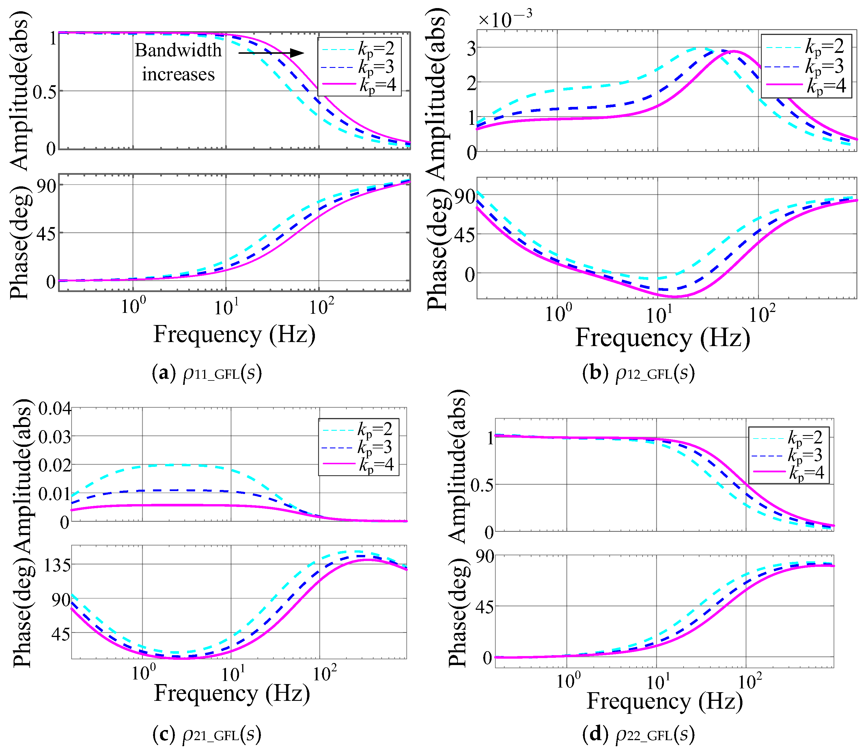
The Bode diagram of the GFL closed-loop transfer function ρGFL is constructed to evaluate its reference-tracking capability, as shown in Figure 2.
Figure 2a,d present the Bode plots of ρ11_GFL(s) and ρ22_GFL(s), which represent the dynamic responses of the active and reactive powers to their corresponding references. It is observed that near 0 Hz, ρ11_GFL(s) = ρ22_GFL(s) = 1, indicating a zero steady-state tracking error. The converter bandwidth is approximately 80 Hz. Below this frequency, the transfer functions remain near unity, enabling effective reference tracking; above 80 Hz, they attenuate toward zero, effectively suppressing high-frequency noise. Additionally, Figure 2b,c present the Bode plots of ρ12_GFL(s) and ρ21_GFL(s), which represent the power coupling terms of the active power when the reactive-power reference changes, and reactive power when the active-power reference changes. From Figure 2b,c, the power coupling magnitudes are small (less than 0.02) and near 0 Hz, indicating there were nearly zero power coupling magnitudes in the steady state.
In the series-connected hybrid control shown in Figure 1b, the PWM reference voltage is the sum of the voltage references generated by the VSG and GFL controls. Consequently, the converter output power is influenced by both control loops, and the overall closed-loop transfer function can be expressed as:
Δ P Δ Q = ρ 11 _ GFL ρ 12 _ GFL ρ 21 _ GFL ρ 22 _ GFL ρ GFL Δ P ref Δ Q ref + ρ 11 _ VSG ρ 12 _ VSG ρ 21 _ VSG ρ 22 _ VSG ρ VSG Δ P ref Δ Q ref
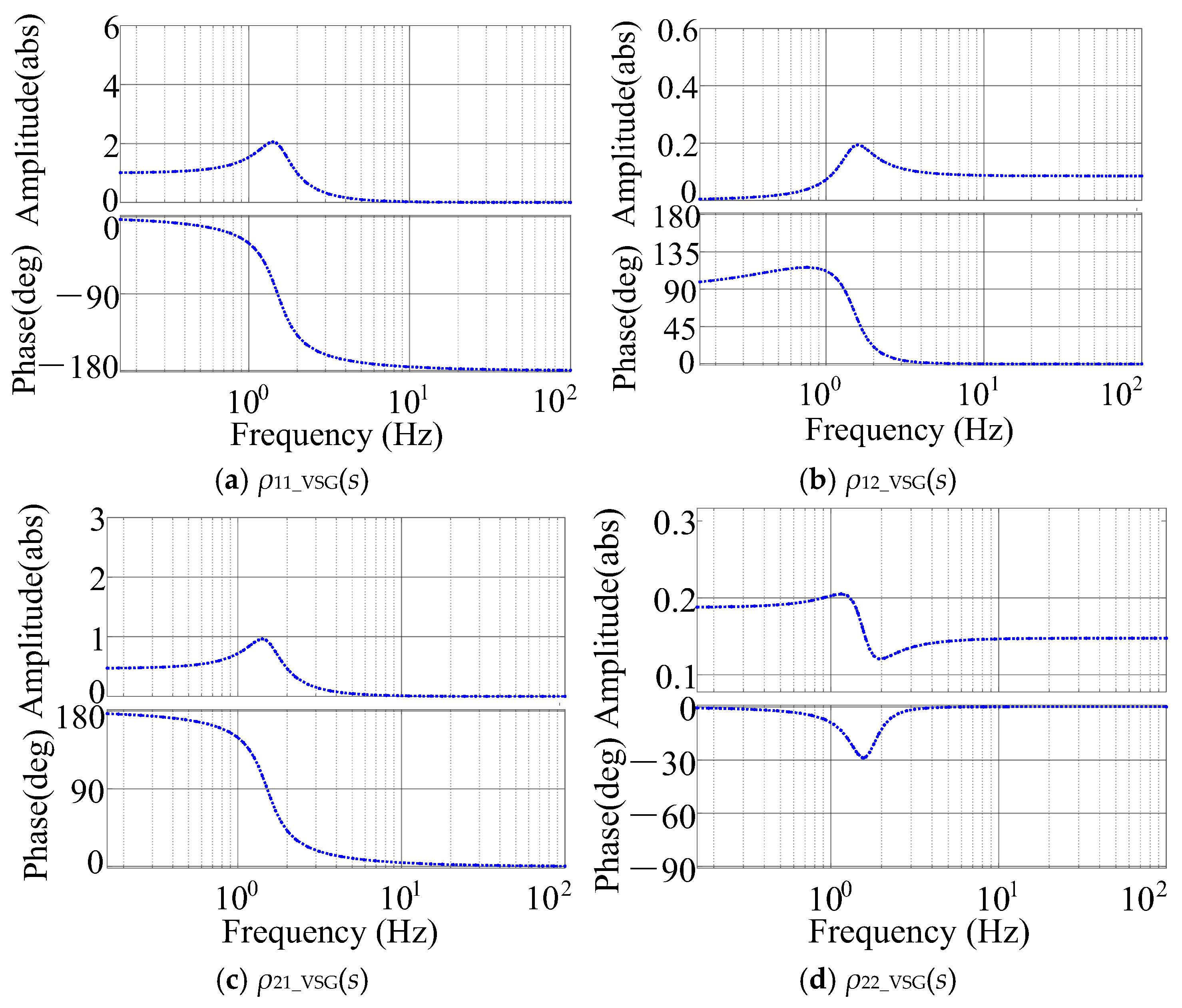
where ρVSG denotes the closed-loop transfer function of the VSG control. According to [12], the Bode plot of ρVSG is shown in Figure 3.
As shown in Figure 3a,d, the bandwidth of the VSG control is approximately 10 Hz, significantly lower than the 80 Hz bandwidth of the GFL control. This indicates that the GFL control exhibits superior reference-tracking performance compared with VSG. When Pref or Qref changes, the converter response is governed by the GFL loop, achieving reference tracking on a millisecond timescale. Additionally, Figure 3b,c depict the power coupling items of traditional VSG controls, which share the same meanings of Figure 2b,c. In Figure 3c, near 0 Hz, the coupling magnitudes of the reactive power when the active-power reference changes is 0.5, indicating that the active and reactive powers cannot be controlled independently. By combining GFL controls in the proposed controller, the power coupling issue can be solved, as shown in Figure 2b,c.

3.2. Time-Division Control Logic: “GFL Dominant in Steady State, GFM Dominant During Transients”

It is noteworthy that the proposed series-connected hybrid control exhibits distinct control mechanisms under steady-state and transient conditions following a time-division logic, whereby “GFL dominance prevails in steady state, while GFM dominance takes over during transients.” This enables a fast power response characteristic of GFL controls under normal operation, and an active–reactive-power support capability characteristic of GFM controls during grid disturbances.

3.2.1. Mechanism of GFL Dominance in Steady States

Under steady-state grid conditions, Figure 2a,d show that ΔPPref = 1 and ΔQQref = 1, indicating that the GFL loop enables zero-error tracking of the power references. This is verified by the simulation results of Figure 4 in Figure 5a,d. As analyzed in Figure 3, the VSG control bandwidth is much lower than that of the GFL loop. Therefore, on a millisecond timescale, the voltage phase and magnitude generated by VSG remain essentially aligned with the grid voltage and are unaffected by changes in Pref and Qref. Consequently, power variations are determined solely by the GFL control.
Correspondingly, in the equivalent circuit of Figure 1a, variations in Pref and Qref during a steady state result in power delivery to the grid only from the GFL current source IGFL, while the VSG-controlled voltage source EVSG remains in phase and magnitude with Vpcc, thus contributing no overall active- or reactive-power delivery.

3.2.2. Mechanism of GFM Dominance During Transients

During a three-phase fault with the receiving-end grid, the proposed series-connected hybrid control enables active–reactive-power support without requiring separate coordination between the GFL and VSG loops or any change in Pref and Qref. The rationale is as follows.
Considering grid-side voltage sag disturbances, the converter output active and reactive power in (14) can be reformulated as:
Δ P Δ Q = ρ 11 _ GFL ρ 12 _ GFL ρ 21 _ GFL ρ 22 _ GFL ρ GFL Δ P ref Δ Q ref + c 11 c 12 c 21 c 22 c VSG Δ δ Δ E
where Δδ and ΔE represent the perturbations in phase-angle difference and voltage magnitude between the converter terminal voltage and the grid-side PCC voltage, respectively. The coefficient matrix cVSG is given by [18,19]:
c 11 = E VSG 0 I c cos γ c 0 c 12 = I c sin γ c 0 c 21 = E VSG 0 I c sin γ c 0 c 22 = I c cos γ c 0
where EVSG0 is the steady-state voltage reference generated by the VSG control; in I c = E g / R 2 + X 2 , R and X are the equivalent resistance and reactance of the transmission line; and in γ c = δ + arctan R / X , δ is the steady-state phase-angle difference between the VSG output angle and the PCC voltage phase.
From (15), the converter output power is determined by both the power references and the voltage deviation between the VSG-generated voltage and the grid voltage. Under steady-state conditions, Δδ and ΔE are zero, and the power dynamics are governed by the GFL loop. During grid faults, however, Δδ and ΔE ≠ 0, and the power references remain unchanged (ΔPref = ΔQref = 0); hence, the power dynamics are dominated by the VSG control characteristics.
In the equivalent circuit of Figure 1a, when a three-phase fault occurs on the grid side, the PCC voltage Vpcc drops, creating a magnitude difference between the VSG-controlled voltage source EVSG and Vpcc. This difference enables the converter to actively inject reactive power to support the grid voltage, as verified by the simulation results of Figure 4 in Figure 6b. The resulting reactive-power increment can be expressed as ΔQ = c22 × ΔE.

4. Simulation Verification

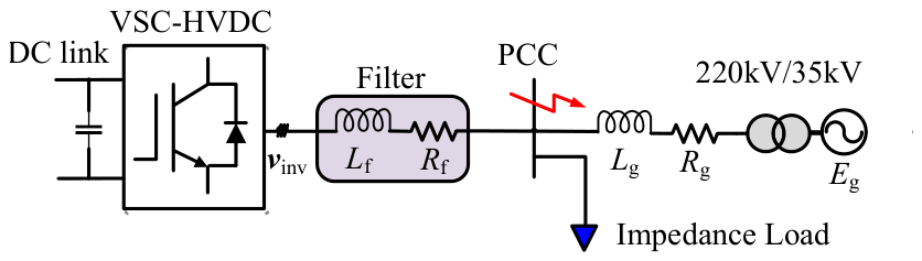
Simulink simulations are conducted on the equivalent topology of a VSC-HVDC system integrated into a receiving-end AC system, as shown in Figure 4, to evaluate the power control performance of the proposed series-connected hybrid control. The synchronization-type hybrid control is adopted as a comparison to assess the transient voltage-support capabilities of both methods. The simulation is conducted by using MATLAB Simulink R2024b with a fixed step simulation solver, and the converter model is an averaged model. The system parameters and control settings are provided in Appendix A. It should be noted that since the proposed controller combines the GFL and GFM structures, its original control parameters reported in Appendix A come from the typical control parameters in GFL and GFM controls, which can be referred from Ref. [20]. Then, the control parameters of the proposed controls can be selected by a trial-and-error method, using simulations to achieve stability during operation. To compare the transient performance of the proposed controller with conventional synchronization-type hybrid controls, the conventional controller parameters are set to be the same as the proposed method, i.e., KP, K,i, kP, k,i, D, and J.
Figure 4. Receiving-end power grid connected to the VSC-HVDC.
Energies 19 04219 g004

4.1. Power-Tracking Performance of the Series-Connected Hybrid Control

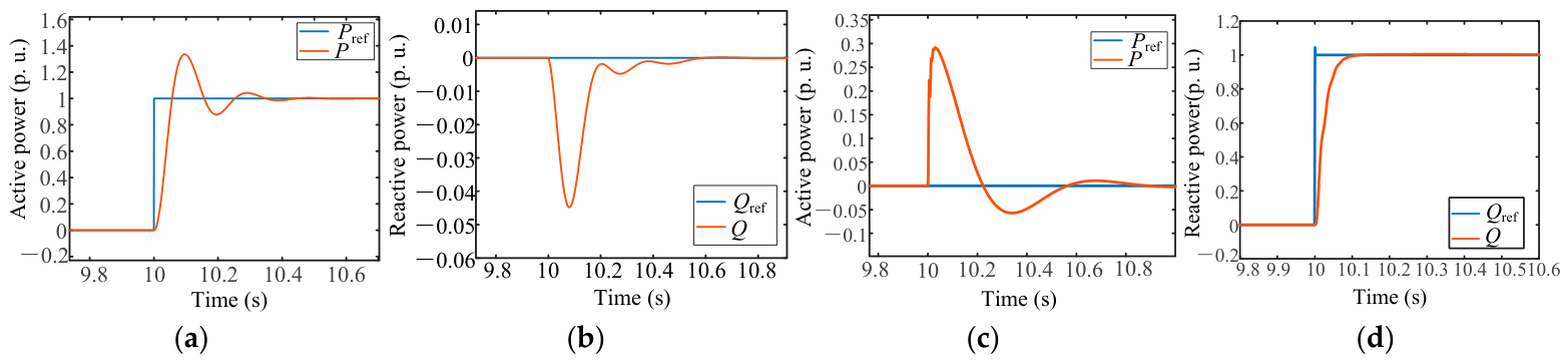
A weak grid with a short-circuit ratio (SCR) of 1.5 is considered. At t = 10 s, a step change of 1 p. u. is applied to Pref while Qref is maintained at 0 p. u. The resulting active- and reactive-power responses are shown in Figure 5a,b. The rise time of the active-power tracking is within 0.2 s, with an overshoot of approximately 20%, which can be reduced by decreasing the proportional gains of the GFL inner and outer loops. The transient coupling component for reactive power is about 0.04 p. u., which is relatively small.
Figure 5d shows the reactive-power response when a 1 p. u. step change is applied to Qref. The converter effectively regulates the reactive power with a rise time of 0.2 s while Pref is set to 0 p. u.; the corresponding active-power transient is depicted in Figure 5c.
These simulation results confirm the analytical findings in Figure 2: at frequencies near 0 Hz, ρ11(s) = ρ22(s) = 1, indicating a zero steady-state error and the precise output power control of the series-connected hybrid scheme.
Figure 5. Active- and reactive-power control performances with the series-connected-type hybrid control: (a) active-power control performance; (b) reactive power when the active power changes; (c) active power when the reactive power changes; (d) reactive-power control performance.
Energies 19 04219 g005

4.2. Comparison of Transient Voltage-Support Capabilities

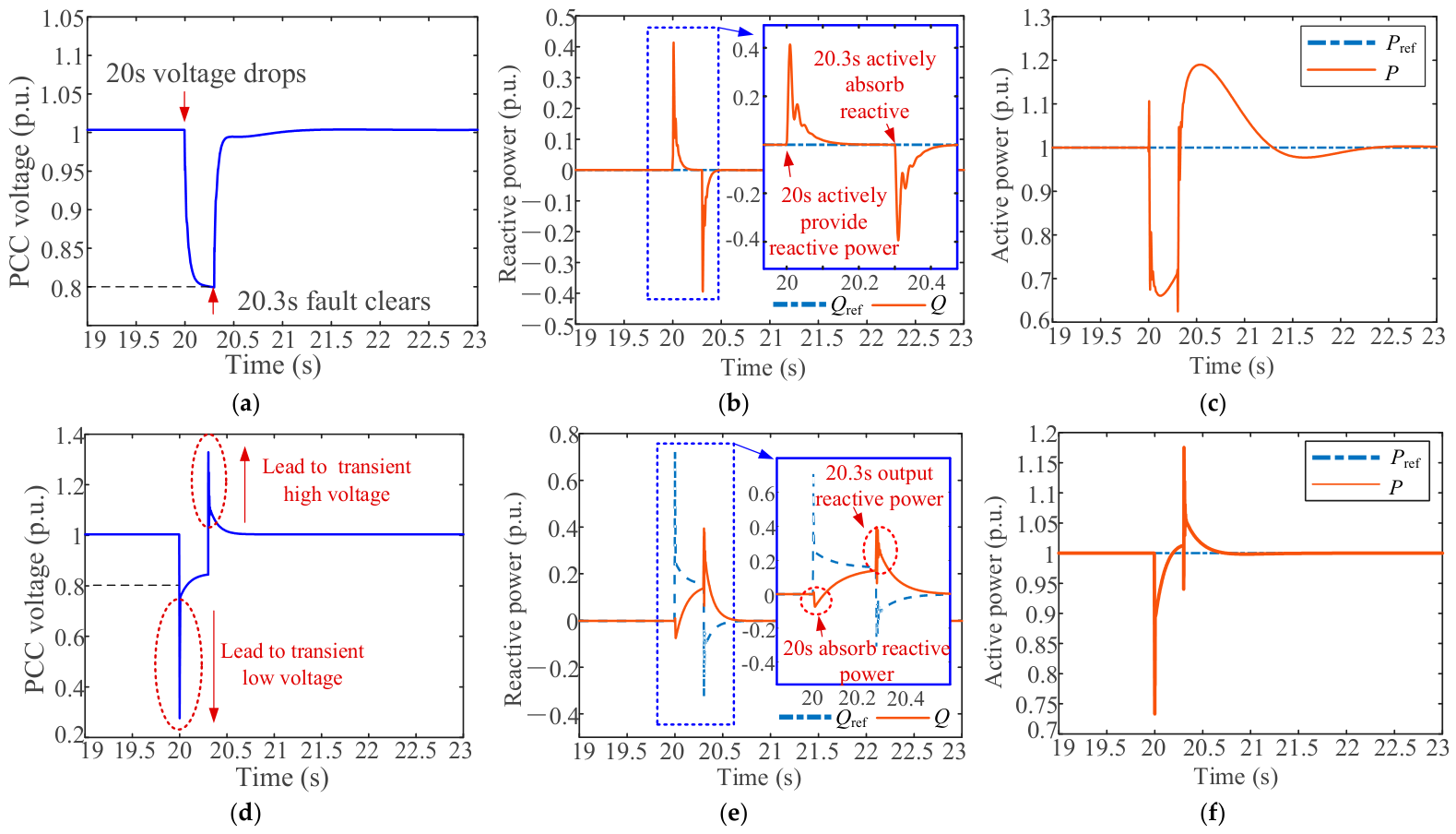
To compare the voltage-support performances between the series-connected hybrid control and the synchronization-type hybrid control, a three-phase-to-ground fault with a grounding resistance of 0.5 Ω is applied at the PCC at t = 20 s, lasting for 0.3 s. Under the proposed series-connected control, the PCC voltage drops by 0.2 p. u. (Figure 6a), with the corresponding reactive-power dynamics shown in Figure 6b. Although Qref remains at 0 p. u., the VSG-controlled voltage source exhibits a magnitude difference ΔE. This difference enables a reactive-power injection at t = 20 s without changing Qref, thereby raising the PCC voltage. Upon fault clearance at t = 20.3 s, the rapid voltage recovery drives ΔE negative, causing the converter to absorb the reactive power (Figure 6b), which in turn mitigates the transient overvoltage (Figure 6a). Figure 6c presents the active-power dynamics during the fault. Notably, while the reactive power is injected, the active power decreases correspondingly with Pref unchanged, ensuring that the converter output current remains below the maximum threshold, consistent with conventional converter requirements during faults [21].
For comparison, the synchronization-type hybrid control, a representative method that has attracted considerable research interest [5,6,7], is selected for voltage control performance. Under the same fault conditions (three-phase ground fault at t = 20 s, lasting 0.3 s), the PCC voltage response under the hybrid synchronization-type control is shown in Figure 6d. Comparing the reactive responses in Figure 6b,e, the proposed series-connected control actively injects reactive power during the fault, supporting the PCC voltage, which drops from 1 p. u. to 0.8 p. u., as seen in Figure 6a. In contrast, due to the degraded PLL-tracking performance under weak-grid conditions, the hybrid synchronization-type control absorbs the reactive power at t = 20 s, causing the PCC voltage to plummet from 1 p. u. to 0.38 p. u., thereby exacerbating the transient low-voltage issue, as seen in Figure 6d.
Figure 6. Transient voltage response of the series-connected-type and hybrid synchronization-type GFL–GFM hybrid controls. (a) Voltage magnitude under the series-connected hybrid control; (b) reactive power under the series-connected hybrid control; (c) active power under the series-connected hybrid control; (d) voltage magnitude under the hybrid synchronization control; (e) reactive power under the hybrid synchronization control; (f) active power under the hybrid synchronization control.
Energies 19 04219 g006
At t = 20.3 s, when the fault is cleared and the system voltage recovers rapidly, the series-connected control absorbs the reactive power, effectively mitigating the overvoltage issue. In contrast, the hybrid synchronization-type strategy, influenced by the slow PLL dynamics, continues to inject reactive power at 20.3 s, as shown by Figure 6e, resulting in a transient overvoltage of up to 1.38 p. u., as seen in Figure 6d. Figure 6f depicts the active power under hybrid synchronization control during the disturbance.
In summary, in regard to the transient voltage stability comparison, the minimum voltage dips of the proposed method and conventional method are 0.8 p. u. and 0.38 p. u., respectively, and the maximum overvoltage of them are 1 p. u. and 1.38 p. u. The recovery time of the two methods are nearly the same, i.e., 0.2 s.
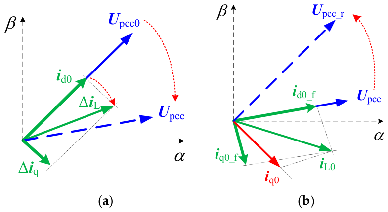
The underlying reason is that the hybrid synchronization-type controlled converter operates essentially as a controlled current source tracking Qref, which is inevitably affected by PLL dynamics. With the increasing penetration of renewable energy, the PCC voltage phase tends to exhibit a lagging phase-angle jump during a three-phase-to-ground fault in the receiving-end grid [17], as depicted in Figure 7a. Upcc0 denotes the steady-state PCC voltage phasor, Upcc represents the post-fault PCC voltage phasor, and id0 is the pre-fault steady-state active current of the converter. Owing to the dynamic behavior of PLLs, a phase-locked error persists. Under the voltage-regulation command, the converter injects a reactive current Δiq, which is oriented perpendicular to the initial PCC voltage vector Upcc0. The resultant output current is denoted as ΔiL, as indicated by the green arrow in Figure 7a. It is evident that ΔiL still leads to Upcc, implying that the converter may momentarily absorb the reactive power following the fault, thus further aggravating voltage instability.
Moreover, during fault recovery, the PCC voltage experiences an advanced phase-angle jump from Upcc to the post-recovery value Upcc_r [17], as illustrated in Figure 7b. Here, id0_f, iq0_f, and iL0 represent the active current, reactive current, and their resultant vector during the fault period, respectively. The projection of iL0 onto the direction perpendicular to Upcc_r yields iq0, whose magnitude exceeds the fault-period reactive current iq0_f. This suggests that at the instant of voltage recovery, the converter may instead inject reactive power, resulting in a reactive-power surplus and, consequently, in transient overvoltage.
During severe phase-angle jumps following grid faults, its power control performance deteriorates, and larger phase jumps lead to poorer reactive controls, potentially deteriorates the grid voltage. Specifically, a lagging phase-angle jump at fault inception [17] can drive the converter current ahead of the grid voltage, causing reactive-power absorption that further depresses the voltage. During voltage recovery, however, a leading phase-angle jump [17] forces the current to lag behind the grid voltage, resulting in an excessive reactive-current injection that amplifies the transient overvoltage.
In summary, the proposed series-connected hybrid control behaves as a controlled current source in a steady state, enabling accurate power reference tracking while exhibiting controlled voltage source characteristics during transients, thus providing superior transient voltage support compared to the existing hybrid synchronization-type control. It is worth noting that the oscillation stability of the proposed series-connected hybrid control under both strong- and weak-grid conditions exhibits characteristics of a hybrid GFM–GFL system. Thus, the oscillation stability of the proposed method under different grid strengths is expected to be stable when the allocation of GFL and GFM is properly configured, which contributes to the accommodation of varying grid strengths. In addition, only a three-phase-to-ground fault condition is considered in this paper; thus, the proposed control is suitable for a three-phase-voltage balanced system. However, when a single-phase-to-ground fault occurs, the control structure should be redesigned to meet the requirement of stable operation under a three-phase-voltage unbalanced system. The above studies under different operating conditions will be addressed in future work.

5. Conclusions

This paper proposes a series-connected GFL–GFM hybrid control for VSC-HVDC converters in weak receiving-end grids, aiming to enhance transient voltage support while preserving steady-state power regulation accuracy. The control constructs the PWM reference voltage as the sum of independent GFL and VSG-based GFM voltage references, enabling a natural “GFL dominates in steady states, GFM dominates during transients” behavior without mode switching.
A closed-loop transfer function model is derived to quantitatively analyze the power dynamics. Frequency response analysis shows that near 0 Hz, the GFL loop ensures zero steady-state tracking errors, while during faults, the GFM loop governs this response, with the reactive-power increment explicitly given by ΔQ = c22·ΔE. Simulation comparisons with the hybrid synchronization-type control under SCR = 1.5 confirm that the proposed method improves the minimum voltage dip from 0.38 p. u. to 0.8 p. u. and suppresses recovery overvoltage from 1.38 p. u. to 1 p. u., demonstrating superior mitigation of both undervoltage and overvoltage.
Key contributions include a simple series-connected architecture, a quantitative analytical framework for transient power dynamics, and a verified performance improvement over existing hybrid controls. Future work will address an adaptive GFL/GFM contribution allocation for varying grid strengths.

Author Contributions

Conceptualization, Z.G.; methodology, Z.G.; software, Z.G.; validation, X.X. and C.F.; formal analysis, Z.G.; investigation, Z.G.; resources, X.X. and S.L.; data curation, X.X.; writing—original draft preparation, Z.G.; writing—review and editing, Z.G. and X.X.; visualization, B.B.; supervision, C.F.; project administration, X.X. and C.F.; funding acquisition, X.X. All authors have read and agreed to the published version of the manuscript.

Funding

This research was funded by the Science and Technology Project of China Southern Power Grid Co., Ltd. (036000KC23090004(GDKJXM20231026)) and by the National Natural Science Foundation of China (52507119).

Data Availability Statement

The datasets presented in this article are not readily available because they consist of project-specific simulator-derived power plant data managed under institutional and research-group data-use restrictions. Requests to access the datasets should be directed to the corresponding author.

Conflicts of Interest

Author Bao, B.; Fu, C.; Li, S. are employed by the company Electric Power Dispatching Control Center of Guangdong Grid Co., Ltd. The remaining authors declare that the research was conducted in the absence of any commercial or financial relationships that could be construed as potential conflicts of interest. The authors declare that this study received funding from the Science and Technology Project of China Southern Power Grid Co., Ltd. (036000KC23090004(GDKJXM20231026)). The funder was involved with the study design and in the decision to submit the study for publication.

Appendix A. System Parameters of the Two Types of GFLGFM Hybrid Controls

Table A1. System parameters of the series-connected-type GFL–GFM hybrid control.
SymbolParametersValueUnit
EgAC system equivalent voltage35kV
VdcDC-link voltage500kV
PbaseRated active power1000MW
QbaseRated reactive power0MVar
PloadRated active-power load800MW
fRated frequency at the PCC50Hz
EpccRated voltage at the PCC220kV
RfFilter resistance10
LfFilter inductance0.95mH
RgGrid-side resistance0.12Ω
LgGrid-side inductance2mH
KP, K,iProportional & integral gains of the GFL power loop PI controller1, 1
kP, k,iProportional & integral gains of the GFL current loop PI controller0.1, 0.3
DDamping coefficient of the VSG active-power loop0.15
JVirtual inertia10
ωrefRated angular frequency100πrad/s
Table A2. System parameters of the hybrid synchronization-type GFL–GFM hybrid control.
SymbolParametersValueUnit
KP,pll, Ki,pllPLL proportional and integral gains180, 3200
KP, K,iProportional and integral gains of the power loop PI controller1, 1
kP, k,iProportional and integral gains of the current loop PI controller0.1, 0.3
DDamping coefficient of the VSG active-power loop0.15
JVirtual inertia10
ωrefRated angular frequency100πrad/s
kQDroop coefficient of the VSG reactive-power loop0.5
RPLLGFL weighting coefficient0.6
RPSCGFM weighting coefficient0.4

References

  1. Shan, Y.; Liu, X.; Xin, H.; Zheng, D. Transient voltage stability analysis and enhancement of grid-following converters considering DC-link voltage control dynamics. IEEE Trans. Power Deliv. 2026, 1–14. [Google Scholar] [CrossRef] [Scilit]
  2. Liu, W.; Yin, C.; Li, F.; Li, X.; Han, L.; Zhang, Y. A novel control strategy to suppress transient overvoltage balancing active power impact reduction caused by commutation failure. Int. J. Electr. Power Energy Syst. 2025, 173, 111401. [Google Scholar] [CrossRef] [Scilit]
  3. Liu, J.; Gui, Y.; Dong, S.; Liu, B.; Zhao, S.; Yang, P.; Lu, M.; Sun, Y. Coordinated AC Fault Ride-Through Strategy for Wind Farms Integration via MMC-HVDC Using DC-Side Energy Storage. Energies 2026, 19, 2935. [Google Scholar] [CrossRef] [Scilit]
  4. Ke, X.; Liu, J.; Zhan, L.; Hu, B.; Nian, H. An adaptive control method for active power reference to enhance the transient stability of grid-forming inverters considering current limitation. Int. J. Electr. Power Energy Syst. 2026, 179, 112036. [Google Scholar] [CrossRef] [Scilit]
  5. Aouini, R.; Marinescu, B.; Kilani, K.B.; Elleuch, M. Synchronverter-based emulation and control of HVDC transmission. IEEE Trans. Power Syst. 2016, 31, 278–286. [Google Scholar] [CrossRef] [Scilit]
  6. Yang, R.; Zhang, C.; Cai, X.; Shi, G.; Li, J.; Miao, Y.; Cao, L. Voltage source control and fault ride-through of VSC-HVDC systems with offshore wind farm integration. Proc. CSEE 2022, 42, 4823–4835. [Google Scholar]
  7. Zhan, L.; Hu, B.; Cao, B.; Huang, Z.; Cheng, X.; Zhang, S.; Huang, X.; Nian, H. Mode-switching mechanism and transient stability enhancement of current-limited GFM-DFIG under shallow grid faults. IEEE Trans. Power Electron. 2026, 41, 11795–11805. [Google Scholar] [CrossRef] [Scilit]
  8. Liu, P.; Xie, X.; Shair, J. Adaptive hybrid grid-forming and grid-following control of IBRs with enhanced small-signal stability under varying SCRs. IEEE Trans. Power Electron. 2024, 39, 6603–6607. [Google Scholar] [CrossRef] [Scilit]
  9. Yu, C.; Wang, Q.; Fang, W.; Wang, Y.; Diao, H.; Xu, H.; Guo, L. Research on Dynamic and steady-state characteristics of grid-following/grid-forming hybrid control based on model predictive control. IEEE Open J. Power Electron. 2025, 6, 909–918. [Google Scholar] [CrossRef] [Scilit]
  10. Xiong, X.; Luo, B.; Guo, C.; Blaabjerg, F. A Novel Hybrid Integrated Grid-Forming and Grid-following Control Method to Enhance Synchronization Stability of VSC. IEEE Trans. Ind. Electron. 2026, 73, 11526–11537. [Google Scholar] [CrossRef] [Scilit]
  11. Zhang, S.; Hu, B.; Qiu, Y.; Hua, B.; Sun, D.; Nian, H. Asymmetrical Fault Ride-Through Enhancement for DFIG-Based WT Based on Sequence Coupling Analysis. IEEE Trans. Ind. Electron. 2026, 73, 2333–2343. [Google Scholar] [CrossRef] [Scilit]
  12. Han, F.; Zhang, X.; Li, M.; Li, F.; Zhao, W. Stability control for grid connected inverters based on hybrid-mode of grid-following and grid-forming. IEEE Trans. Ind. Electron. 2024, 71, 10750–10760. [Google Scholar] [CrossRef] [Scilit]
  13. Li, M.; Zhang, X.; Guo, Z.; Wang, J.; Li, F. The dual-mode combined control strategy for centralized photovoltaic grid-connected inverters based on double-split transformers. IEEE Trans. Ind. Electron. 2021, 68, 12322–12330. [Google Scholar] [CrossRef] [Scilit]
  14. Gao, X.; Zhou, D.; Anvari-Moghaddam, A.; Blaabjerg, F. Seamless switching method between grid-following and grid-forming control for renewable energy conversion systems. IEEE Trans. Ind. Appl. 2025, 61, 597–606. [Google Scholar] [CrossRef] [Scilit]
  15. Song, S.; Sun, K.; Li, K.; Dong, Y.; Wen, Y.; Zhang, Z.; Li, M. An improved mixture ratio control strategy for zero-disturbance switching of grid-forming and grid-following inverters. IEEE Trans. Ind. Appl. 2025, 61, 8373–8382. [Google Scholar] [CrossRef] [Scilit]
  16. Li, M.; Zhang, X.; Guo, Z.; Pan, H.; Ma, M.; Zhao, W. Impedance adaptive dual-mode control of grid-connected inverters with large fluctuation of SCR and its stability analysis based on d-partition method. IEEE Trans. Power Electron. 2021, 36, 14420–14435. [Google Scholar] [CrossRef] [Scilit]
  17. Huang, L.; Xin, H.; Li, Z.; Ju, P.; Yuan, H.; Lan, Z.; Wang, Z. Grid-Synchronization Stability Analysis and Loop Shaping for PLL-Based Power Converters with Different Reactive Power Control. IEEE Trans. Smart Grid 2020, 11, 501–516. [Google Scholar] [CrossRef] [Scilit]
  18. Wen, T.; Zhu, D.; Zou, X.; Jiang, B.; Peng, L.; Kang, Y. Power coupling mechanism analysis and improved decoupling control for virtual synchronous generator. IEEE Trans. Power Electron. 2021, 36, 3028–3041. [Google Scholar] [CrossRef] [Scilit]
  19. Li, M.; Wang, Y.; Hu, W.; Shu, S.; Yu, P.; Zhang, Z.; Blaabjerg, F. Unified modeling and analysis of dynamic power coupling for grid-forming converters. IEEE Trans. Power Electron. 2022, 37, 2321–2337. [Google Scholar] [CrossRef] [Scilit]
  20. Su, K.; Xie, X.; Gong, Z.; Liu, H.; Sun, D.; Wang, Y. Fast Frequency Response Analysis for Grid- Following and Grid-Forming Controlled BESS Considering Voltage Coupling Effect. IEEE Trans. Power Deliv. 2025, 40, 2412–2425. [Google Scholar] [CrossRef] [Scilit]
  21. Cai, H.; Guo, Q.; Yang, R.; Huang, L.; Shi, G.; Gu, H.; Su, M. Dual-end grid-forming control of flexible DC transmission system for weak grid interconnection. Electr. Power Autom. Equip. 2023, 43, 202–209. [Google Scholar]
Figure 1. Proposed series-connected-type GFL–GFM hybrid control strategy for grid-tied VSC-HVDC. (a) Equivalent circuit of the VSC-HVDC converter with the series-connected hybrid control; (b) the series-connected GFL–GFM hybrid control structure; (c) the VSG power control loop.
Energies 19 04219 g001
Figure 2. Bode diagrams of closed-loop transfer functions under different proportional gains of the GFL power loop.
Energies 19 04219 g002
Figure 3. Bode diagrams of the closed-loop transfer functions of the VSG control.
Energies 19 04219 g003
Figure 7. Phasor diagrams of the PCC voltage and VSC output current when the three-phase-to ground fault occurs and is cleared. (a) Output voltage and current of VSC when the fault occurs; (b) output voltage and current of VSC when the fault is cleared.
Energies 19 04219 g007
Disclaimer/Publisher’s Note: The statements, opinions and data contained in all publications are solely those of the individual author(s) and contributor(s) and not of MDPI and/or the editor(s). MDPI and/or the editor(s) disclaim responsibility for any injury to people or property resulting from any ideas, methods, instructions or products referred to in the content.