1. Introduction
The increasing share of variable renewable energy sources creates a growing need for flexible and reliable energy-storage technologies. Among the available storage solutions, pumped-storage hydropower remains one of the most mature large-scale technologies, providing balancing capacity, peak-load support, and grid flexibility [
1,
2,
3]. In this context, post-mining infrastructure, including inactive shafts and underground workings, is increasingly considered as a potential basis for underground pumped-storage hydropower systems. Colas et al. [
4] reviewed the conversion of abandoned coal mines into underground pumped-storage systems, with particular attention to underground reservoirs. Lyu et al. [
5] identified key technical concerns and research directions for pumped storage in abandoned mine shafts. Other studies have analysed the technical feasibility and economic aspects of underground pumped-storage systems at selected mine sites [
6,
7]. The earlier Budryk case study [
8] considered a different storage principle—gravity storage based on the vertical displacement of a solid mass within the shaft—and did not investigate the use of the shaft as the lower water reservoir of an underground pumped-storage hydropower system.
In addition to pumped-storage concepts, post-mining shafts and underground workings have also been analysed for other energy-storage applications. Recent studies have considered their use for compressed-air energy storage [
9], mine-shaft energy storage [
10], gravity-based storage [
11,
12], and mine water hydropower systems [
13].
This study addresses the question of whether, and under what technical conditions, a deep post-mining shaft can be considered as the lower reservoir of an underground pumped-storage hydropower system. In this context, the suitability of a shaft cannot be assessed only on the basis of its depth or available void volume. It also depends on the usable hydraulic head, working volume of the lower reservoir, turbine operating range, water-return strategy, shaft sealing, hydraulic isolation of horizontal workings, and the ability to adapt the existing underground infrastructure for cyclic operation.
The aim of this paper is therefore to apply a preliminary, case-study-based technical assessment to Budryk Shaft II, which had previously been selected within the HESS project through a multi-criteria decision analysis of candidate mine shafts for PSH configurations in which the shaft itself serves as the lower reservoir. The screening considered shaft depth, availability of space for an upper reservoir, shaft configuration, hoisting infrastructure, methane hazard, and mine dewatering conditions. Budryk Shaft II obtained the highest score among the analysed Polish candidates and was therefore adopted as the reference PSH site for the subsequent detailed engineering assessment [
14]. The Budryk II case should therefore be regarded as the engineering-assessment stage following an earlier MCDA-based site-screening process rather than as an independently selected case. The assessment integrates shaft geometry, usable hydraulic head, the working volume of the lower reservoir, turbine operating parameters, staged pumping requirements, and underground infrastructure constraints within a single preliminary technical and pumping-energy assessment.
The work was carried out within the RFCS co-funded project “Hybrid Energy Storage System using post-mining infrastructure” (HESS), in which a preliminary design of an underground power-generation unit and water-pumping system was developed for a pumped-storage hydropower plant intended for future implementation in a mine shaft after cessation of its current mining function The adopted configuration includes a high-head Pelton turbine of type PV3i-790/160 (VOITH Hydro GmbH & Co. KG, Heidenheim, Germany), with a rated turbine output of 5287 kW (approximately 5.3 MW), supplied through a DN400 pressure pipeline divided into pressure zones. The turbine parameters were taken from the supplier documentation [
15]. The turbine is coupled to a 6.3 kV synchronous generator with a rated power reported as 5800 kW in the project documentation [
16], while the shaft layout, pipeline assumptions, and underground infrastructure constraints were taken from the preliminary design documentation [
16,
17,
18,
19]. General information on Pelton turbines and shut-off valves was used only to support the selection of the turbine type and hydraulic-control concept [
20,
21]. In pumping mode, water is returned in stages from the lower shaft reservoir through intermediate mine levels to the surface discharge point [
22], from where a separate surface-side hydraulic connection is required to convey the water to the upper reservoir. The working volume of the lower reservoir was assumed to be approximately 12,000 m
3 [
16,
19].
Previous studies have addressed individual components of the UPSH development problem. Reviews have synthesised underground-reservoir concepts and key research challenges [
4,
5], whereas feasibility and economic studies have evaluated selected mine sites [
6,
7]. More recent studies have addressed site-selection methods and detailed case studies of underground reservoirs, including goafs and networks of mine galleries, storage capacity, preliminary energy balance, structural stability, and groundwater interaction [
23,
24,
25,
26,
27,
28]. The earlier Budryk case study [
8] concerned solid-mass gravity storage and therefore did not develop a water-based UPSH configuration.
Against this background, the scientific contribution of the present study is methodological and site-specific rather than the introduction of new hydraulic machinery. Using a common working water volume of 12,000 m3, the study integrates: (i) the shaft itself as the lower reservoir; (ii) an in-shaft turbine–generator unit installed at approximately −900 m and matched to a supplier-defined high-head Pelton operating point; (iii) an approximately 900 m long DN400 penstock divided into pressure zones; (iv) the structural adaptation and hydraulic isolation required at the shaft stations; and (v) a three-stage water-return route based on the existing mine drainage infrastructure. This integrated assessment advances the Budryk case from a general storage-potential analysis to a component-level preliminary engineering assessment of a water-based UPSH system. It also identifies system-level constraints and subsystem interdependencies that cannot be inferred from shaft depth and volume alone, particularly the dominant contribution of Stage III to the calculated pumping-energy demand.
Accordingly, the study does not claim that abandoned mine shafts are generally suitable for pumped-storage applications. Its transferable contribution lies in the integrated assessment approach and in identifying the technical interfaces that must be verified, while equipment selection and design parameters remain site-specific. The multi-criteria site-selection stage preceded the present study and identified Budryk Shaft II as the reference PSH location; therefore, the assessment framework presented here does not constitute a new ranking model, but rather a subsequent engineering assessment of the MCDA-selected site. The principal conditions requiring site-specific verification include sufficient shaft depth and working reservoir volume, compatibility between hydraulic head and turbine selection, technically feasible staged pumping, hydraulic isolation of mine workings, shaft-lining behaviour, and optimisation of the water-return system.
Recent research has progressed from general UPSH concepts towards site-selection methods and detailed case studies. Chen et al. [
23] proposed a two-step framework for screening and comprehensively assessing abandoned coal-mine sites. Jiang et al. [
24] evaluated coal-mine goafs as underground reservoirs, considering storage capacity, usable volume, ventilation, and system performance. Menéndez et al. [
25] assessed an underground lower reservoir and a preliminary energy balance for a closed coal mine in North-western Spain, while a related study examined the stability of underground infrastructure and air-pressure effects during operation [
26]. Belgian case studies have addressed site-specific technical and economic conditions [
27], as well as interactions between underground reservoirs and surrounding groundwater [
28]. Together, these studies identify reservoir hydraulics, geotechnical stability, groundwater exchange, and site selection as central issues in UPSH development.
2. Materials and Methods
2.1. Assessment Framework
The assessment framework adopted in this study consisted of six consecutive stages. First, the shaft geometry was characterised in terms of total depth, diameter and the location of the turbine–generator unit. The gross geometric volume of the shaft section below the unit was distinguished from the operational working volume of the lower reservoir. A working volume of 12,000 m3 was adopted as the common calculation basis for the pumping analysis.
Second, the gross design head and the rated net head were defined. The gross design head was set at 900 m, whereas the rated net head of 837.81 m was adopted from the turbine supplier’s documentation [
15]. The latter value was used to characterise the rated operating point and was not independently recalculated in the present study.
Third, the generation side was characterised using the supplier-defined rated operating point of the turbine, including a discharge of 0.71 m
3/s, a rated turbine efficiency of 90.82%, and a rated turbine output of 5287 kW [
15]. The hydraulic power of the water stream was used only as an approximate consistency check. The exact rated turbine output was adopted from the supplier’s documentation rather than recalculated from rounded hydraulic input data. The generator was characterised using the parameters reported in the project documentation: a rated power of 5800 kW, a rated voltage of 6.3 kV, and a rated power factor of 0.9 [
16]. These quantities were treated as reported equipment parameters and were not used to calculate the generated electrical energy.
Fourth, the three-stage arrangement for returning water from the lower reservoir to the surface discharge point was characterised, including the pump configuration assigned to each stage.
Fifth, pumping time and preliminary pumping-energy demand were estimated separately for each stage for the transfer of the same working volume of 12,000 m3. For Stage I, aggregate nominal capacity and power were used for the four pumps operating simultaneously, whereas the calculations for Stages II and III were based on one operating pump in each stage. Pump load in these stages was matched to the effective throughput of Stage I.
Sixth, the principal infrastructure constraints were identified, including shaft sealing, hydraulic isolation of horizontal workings, verification of the shaft lining, and the requirements associated with installing and operating the underground machinery. This calculation sequence maintained a single working-volume basis for the pumping analysis while treating the rated turbine output, generator nameplate parameters, and pumping-energy demand as separate quantities. The theoretical energy capacity associated with the full geometric shaft volume was not determined.
2.2. Case-Study Basis and Input Data
The analysis was carried out for a conceptual underground pumped-storage hydropower system using a post-mining shaft as the lower water reservoir. Budryk Shaft II was selected as the case-study object because of its considerable depth, large diameter, existing underground infrastructure, and potential connection with the mine drainage system. The study used technical data from the HESS project documentation [
17,
19], preliminary design documentation [
16,
18], supplier documentation for the turbine–generator unit [
15], and pump characteristics [
22].
Technical reports, preliminary design documentation, and supplier information were used as sources of site-specific input data, including shaft geometry, turbine parameters, generator nameplate data, pump characteristics, pressure-pipeline assumptions, and underground infrastructure constraints. These sources were required because the study concerns a specific post-mining shaft and a site-specific preliminary design. The general scientific interpretation, comparison with other energy-storage technologies and discussion of technological limitations were based on peer-reviewed literature and recognised energy-storage reference sources.
The input data and adopted calculation assumptions comprised the shaft depth and diameter, the location of the underground machine zone, the working volume of the lower reservoir, the gross and rated net heads, the rated operating point of the turbine, the generator nameplate parameters, the pressure-pipeline layout, the three-stage pumping arrangement, and the principal underground infrastructure constraints [
15,
16,
17,
18,
19,
22]. Calculations involving water properties were performed using a water density of 1000 kg/m
3 and gravitational acceleration of 9.81 m/s
2.
The rated operating point of the Pelton turbine comprised a gross design head of 900 m, a rated net head of 837.81 m, a discharge of 0.71 m
3/s, a rated turbine efficiency of 90.82%, and a rated turbine output of 5287 kW [
15]. These values were adopted directly from the supplier’s technical documentation. The rated turbine output is descriptively rounded to approximately 5.3 MW where appropriate. The coupled synchronous generator was characterised using the parameters reported in the project documentation: a rated power of 5800 kW, a rated voltage of 6.3 kV, and a rated power factor of 0.9 [
16]. Because the available project documentation does not unambiguously identify 5800 as an apparent-power rating or provide a verified generator efficiency, these parameters were not used to calculate the generated electrical energy.
Budryk Shaft II has a total depth of approximately 1158 m and a diameter of 9 m, while the underground machine zone was assumed to be located at a depth of approximately 900 m [
16,
17,
18,
19]. A working volume of 12,000 m
3 was adopted for the lower reservoir and applied consistently throughout the pumping-time and pumping-energy calculations. The greater gross geometric volume available below the machine zone was not treated as the working volume and was not used to determine a separate theoretical energy-storage capacity.
In the source documentation, Budryk Shaft II is described as an exhaust ventilation shaft equipped with a main ventilation-fan station; the HESS concept therefore concerns its prospective adaptation for energy-storage purposes after cessation of its current mining function [
14].
The purpose of the calculations was not to prepare a final detailed design or determine the verified operating efficiency of the complete system but to establish the principal technical parameters required to assess whether the analysed shaft could be adapted as the lower reservoir of a high-head underground pumped-storage hydropower plant. The pumping-energy results should therefore be interpreted as preliminary calculation-based estimates derived from nominal pump capacities and powers and the proportional power–flow assumption described in
Section 2.6. They do not represent measured electrical-energy consumption. Complete pump-performance curves, verified operating points, motor-efficiency data, and hydraulic-network measurements would be required for a measurement-validated assessment.
2.3. Lower-Reservoir Geometry and Working-Volume Definition
The lower reservoir was assumed to occupy the usable section of Budryk Shaft II located below the support structure of the turbine–generator unit [
16,
17]. For the geometrical assessment, this section of the shaft was approximated as a vertical cylinder with a constant internal diameter. Its gross geometrical volume was determined according to Equation (1):
where:
—gross geometrical volume of the shaft section available for the lower reservoir, m3;
—internal shaft diameter, m;
—usable height of the shaft section below the turbine–generator support structure, m.
The geometrical calculation used the shaft dimensions and turbine–generator installation level specified in
Section 2.2. The usable height
was defined as the vertical distance between the underside of the machine-support zone and the bottom of the shaft section available for water storage. The gross geometrical volume obtained from Equation (1) is presented in the Results section.
The gross geometrical volume and the operational working volume were treated as separate quantities. The gross geometrical volume represents the total spatial capacity of the analysed shaft section, whereas the working volume represents the amount of water adopted as the common basis for the operational calculations. A working volume of 12,000 m3 was adopted as an input assumption and subsequently applied to the pumping-time and pumping-energy calculations. It was not derived directly from Equation (1) and did not imply the complete use of the available shaft volume.
The difference between the gross geometrical volume and the adopted working volume allows for operational clearance, residual water, local structural and installation constraints, and shaft sections unavailable for active cyclic operation. The gross geometrical volume was compared with the adopted working volume only to verify whether the assumed amount of water could be accommodated within the available shaft section. It was not used to calculate a separate theoretical energy-storage capacity.
The rated hydraulic parameters used for turbine and pressure-pipeline selection are discussed in
Section 2.4, whereas the calculation procedure for pumping time and preliminary pumping-energy demand is presented in
Section 2.6.
2.4. Turbine–Generator and Pressure-Pipeline Selection
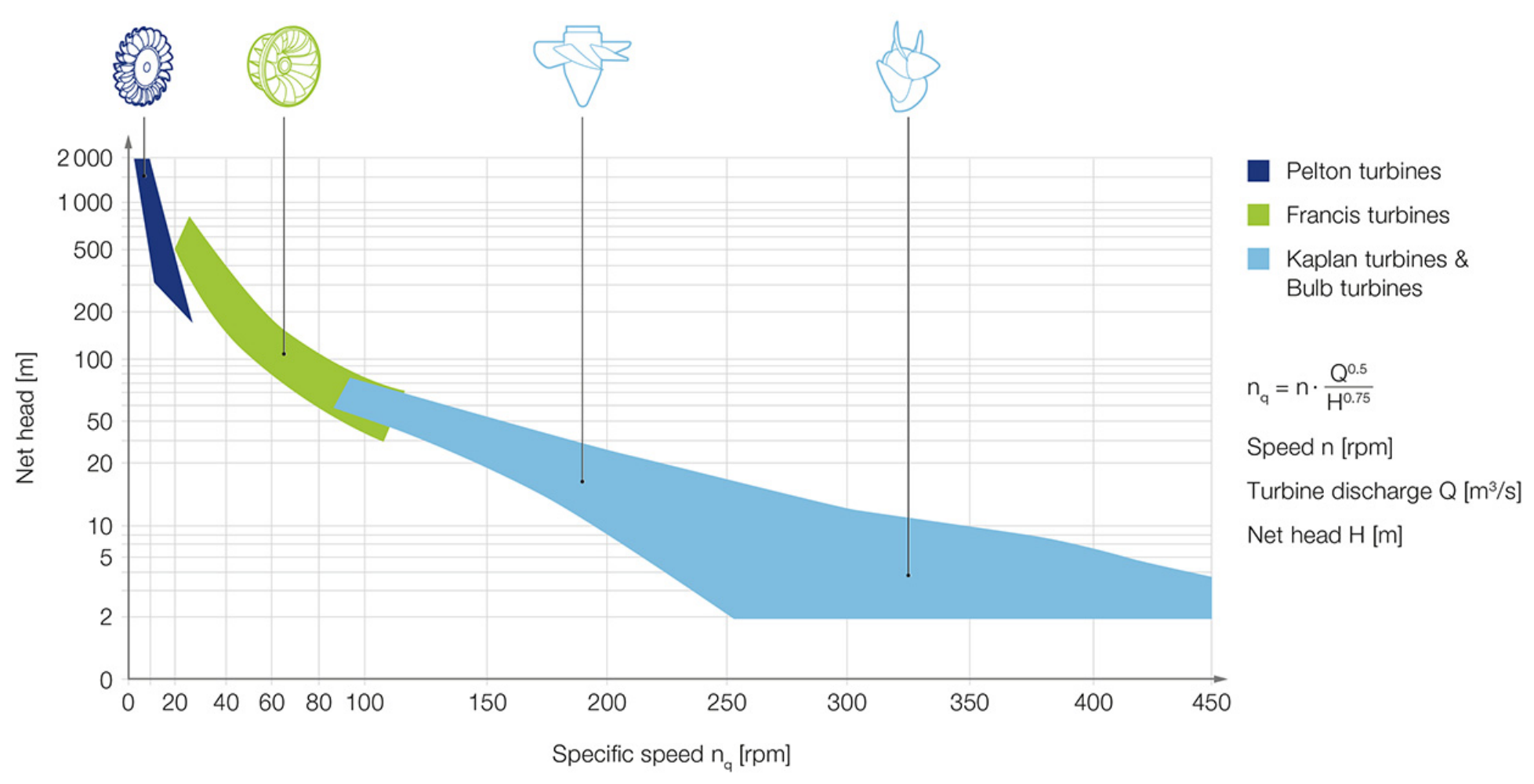
The turbine type was selected by comparing the available hydraulic head and required discharge with the typical operating ranges of the principal hydropower turbine types. These parameters affect turbine efficiency, controllability, and operational stability. Kaplan, Francis, and Pelton turbines operate within different combinations of head and discharge, and the application ranges used for the preliminary comparison are shown in
Figure 1 [
20,
21].
For the analysed configuration, the combination of a very high hydraulic head and a relatively low discharge falls within the typical operating range of Pelton turbines. A vertical Pelton turbine equipped with three internally regulated nozzles was therefore adopted on the basis of general hydropower practice and the supplier-proposed configuration [
15,
20,
21]. Because a Pelton turbine is an impulse machine and cannot operate in reverse as a pump, water return is provided by a separate staged pumping system described in
Section 2.6.
The rated operating parameters of the turbine were adopted directly from the supplier documentation. They comprised a gross design head of 900 m, a supplier-calculated head loss of 62.19 m, a rated net head of 837.81 m, and a rated discharge of 0.71 m
3/s [
15]. The supplier-specified rated turbine output is 5287 kW and may be referred to descriptively as approximately 5.3 MW. This value was treated as a rated equipment parameter and was not recalculated from the rounded values of head, discharge, and turbine efficiency.
The turbine was assumed to be directly coupled to a synchronous generator with a V1 vertical mounting arrangement included in the proposed configuration. According to the budgetary offer prepared by Voith Hydro GmbH & Co. KG, Division Small Hydro (St. Pölten, Austria), the proposed generator has a rated apparent power of 5800 kVA, a rated voltage of 6.3 kV, a rated power factor of 0.9, a rated speed of 1500 rpm, and a frequency of 50 Hz [
15]. The final generator manufacturer and model had not been selected at this preliminary design stage. Because verified generator-efficiency data were unavailable, the generator rating was not used to calculate the generated electrical energy. Instead, the rated turbine shaft output was used only to determine an upper bound for the single-cycle energy output.
The water-supply system was based on an approximately 900 m-long DN400 penstock connecting the upper reservoir to the underground turbine–generator unit. The nominal diameter was adopted from the turbine supplier’s recommendation [
15]. Owing to the increase in hydrostatic pressure with shaft depth, the preliminary pipeline design was divided into PN40, PN63, and PN100 pressure zones. The strength assessment and selection of pipe sections were performed separately for each zone, with higher pressure classes assigned to progressively greater depths [
16].
The preliminary pipe-wall sizing reported in the project documentation accounted for hydrostatic pressure and an assumed surge allowance equal to 35% of the static pressure. This resulted in design pressures of 4.324, 7.549, and 11.919 MPa and selected wall thicknesses of 12.5, 16, and 20 mm for the three successive zones. Because the surge allowance was not obtained from transient-flow modelling, these calculations provide preliminary pipe-wall sizing only. The final pressure-zone classification and the allowable pressures of the complete penstock assembly, including pipes, flanges, valves, expansion joints, supports, and anchorage, must be verified during detailed design against the maximum and minimum pressure envelopes determined from transient-flow analysis.
Under normal operating conditions, turbine discharge is regulated by changing the position of the needles within the three nozzles. Jet deflectors are used during sudden load rejection, emergency shutdown, or overspeed conditions. Their rapid movement diverts the water jets away from the runner, reducing turbine torque without requiring an immediate interruption of flow through the penstock [
15,
16,
21]. The needles are subsequently closed at a controlled rate and, if complete hydraulic isolation of the turbine is required, the sequence is completed by closing the main DN400 ball valve upstream of the turbine manifold. The preliminary shutdown sequence was therefore defined as follows: jet deflectors, needle nozzles, and main inlet valve.
This control sequence was adopted as a preliminary means of limiting rapid flow changes and reducing the risk of water hammer. However, it was not treated as a quantitative verification of transient pressures. A complete transient hydraulic analysis of the penstock, valves, and turbine-control sequence was outside the scope of the present assessment and would be required during detailed system design.
2.5. Structural Adaptation, Shaft-Lining Sealing, and Hydraulic Isolation
The underground machine zone was assessed with regard to the integration of the turbine–generator unit, DN400 penstock, main shut-off valve, hydraulic power unit, and service-access infrastructure. The turbine–generator unit was assumed to be installed at approximately the −900 m level [
15,
16]. The assessment covered spatial integration, the preliminary load-transfer arrangement, maintenance access, and the interfaces requiring structural or hydraulic sealing. It did not constitute a final structural design of the underground machine zone.
Two principal structural functions were considered: supporting the turbine–generator unit and providing safe access for installation, inspection, and maintenance. The original concept of a steel lower platform was screened in terms of prefabrication, underground transport, and installation simplicity. However, owing to the expected static and dynamic actions generated by the turbine–generator set, a massive reinforced-concrete foundation was adopted as the preferred preliminary support solution [
16]. The assessment criteria included structural mass and stiffness, vibration transmission, stability of machine alignment, load transfer to the surrounding shaft structure, and durability under humid underground conditions.
The selection of the reinforced-concrete foundation was qualitative at the present stage. Final verification would require the actual static and dynamic machine loads, anchorage forces, natural frequencies of the machine–foundation–shaft system, and the load-bearing capacity of the shaft lining and surrounding rock mass. Consequently, the preliminary selection of the foundation type should not be interpreted as confirmation that vibration, resonance, and structural-strength requirements have already been satisfied.
The service-platform concept was assessed with respect to personnel access, inspection routes, fall protection, transfer of components between platform levels and access to valves, the hydraulic power unit, and other auxiliary equipment. Guardrails, fixed ladders, self-closing safety gates, handling openings, and protected pipe penetrations were treated as necessary elements of the service infrastructure [
16]. The assessment followed the principles applicable to permanent means of access to machinery, including working platforms, guardrails, safety gates, and fixed ladders, as specified in PN-EN ISO 14122-2, PN-EN ISO 14122-3, and PN-EN ISO 14122-4 [
29,
30,
31].
The shaft-lining sealing assessment covered the continuity and condition of the reinforced-concrete lining, existing cracks and construction joints, service penetrations and the interfaces between the lining, machine foundation, and hydraulic installations. As reported in the HESS project documentation [
18,
19], selected concretes and protective coatings had previously been assessed through gas-permeability testing, water- and brine-penetration testing, and long-term corrosion-resistance testing under chemically aggressive exposure conditions. The latter included chloride-, magnesium-, and sulphate-containing solutions, as well as hydrochloric acid and simulated saline mine water. These material-level tests supported the preliminary identification of sealing and protective measures and the definition of requirements for subsequent sealing design, operation, and maintenance. However, they do not constitute a verification of leakage through the complete shaft-lining–rock-mass system. Accordingly, no final coating system, permissible leakage rate, or detailed application procedure is specified at the present stage. The project-level geomechanical reference analysis cited in this study was performed using UDEC version 5.0 (Itasca Consulting Group, Inc., Minneapolis, MN, USA) [
17].
The use of the shaft as the lower reservoir requires hydraulic separation of the water-filled shaft section from shaft stations and adjacent horizontal workings. The assessment therefore included water-retaining dams at the relevant shaft connections, with particular attention paid to the 1050 m and 1158 m levels [
16,
32]. Adjacent workings were not assigned additional active storage capacity in the adopted reservoir calculation. Any future inclusion of such workings in the working reservoir would require a separate geometrical survey, structural assessment, and verification of long-term hydraulic tightness.
The preliminary screening of dam types was based on Polish underground-mining guidance concerning the liquidation and securing of shafts and shaft-adjacent workings [
32]. The screening criteria included the maximum hydrostatic pressure, excavation geometry, rock-mass strength and discontinuities, required tightness, and the ability to transfer hydraulic loads from the dam into the surrounding rock mass. Because the guidance was not developed specifically for cyclic underground pumped-storage operation, it was used only as a conceptual basis for identifying possible dam arrangements and the required verification checks.
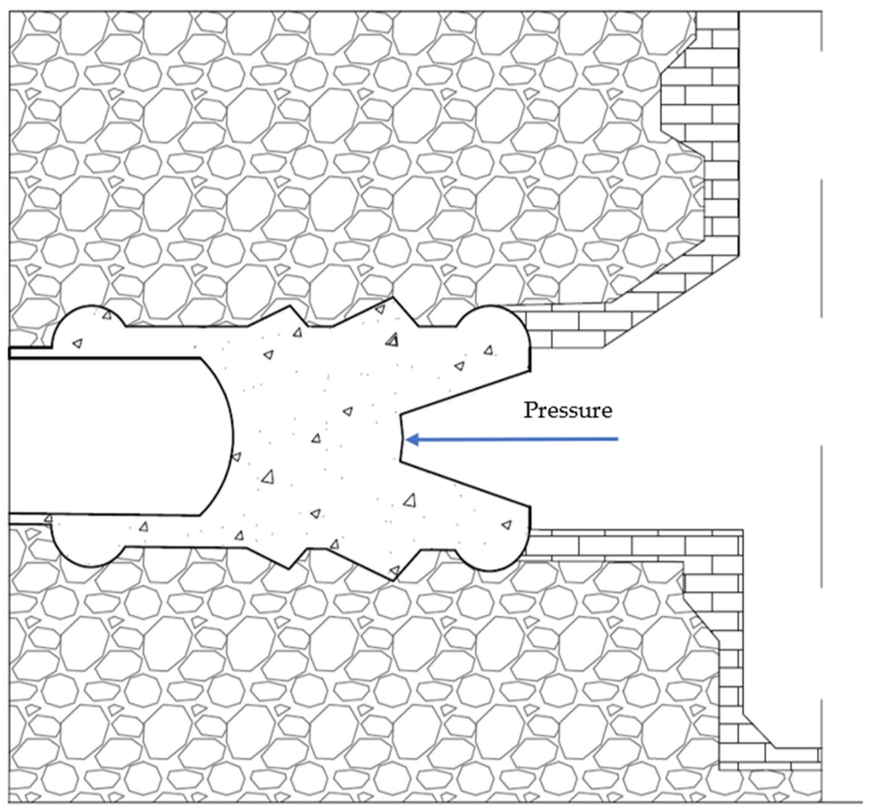
For working pressures exceeding 0.5 MPa, a concrete pyramid dam was treated as the reference solution [
32]. A multi-stage retaining arrangement would be considered if the required thickness of a single dam section exceeded approximately 2.5 m or if weak or fractured rock-mass conditions made a single-stage arrangement unsuitable. Additional grouting, anchoring, and local rock-mass reinforcement may be required to reduce the hydraulic gradient, limit seepage, and improve load transfer.
The preliminary verification framework included resistance to shear and sliding at the dam–rock interface, bearing pressure on the surrounding rock, structural integrity of the dam body, and hydraulic tightness. The underlying project documentation also provides preliminary analytical relationships for determining dam thickness and checking shear resistance and bearing pressure on the surrounding rock mass for both single-stage and multi-stage concrete dams. However, no site-specific dam thickness, reinforcement arrangement, or grouting extent was determined because the final excavation geometry, verified rock-mass parameters, interface properties, and design transient pressure were not available.
Figure 2 therefore represents only the structural principle of hydraulic isolation. Detailed geotechnical investigation, transient-pressure analysis, and structural dimensioning would be required before implementation.
2.6. Staged Pumping System and Pumping-Energy Assessment
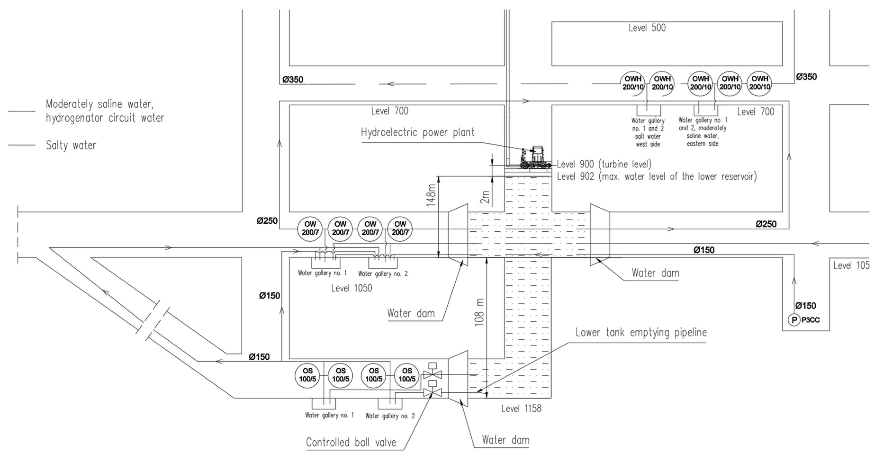
The return of water from the lower shaft reservoir to the surface discharge point was assessed as a three-stage process using the existing mine drainage infrastructure and intermediate underground levels. The adopted sequence comprised Stage I, from the 1158 m level to the 1050 m level; Stage II, from the 1050 m level to the 700 m level; and Stage III, from the 700 m level to the surface [
16,
19]. The staged arrangement was adopted because it is compatible with the available underground infrastructure and avoids the need for direct pumping over the entire elevation difference using a single pumping unit. However, it was not treated as an energy-optimised pumping system designed specifically for cyclic energy storage.
The adopted staged pumping arrangement is shown schematically in
Figure 3.
The same working water volume of 12,000 m
3, defined in
Section 2.3, was assigned successively to each pumping stage. The intermediate mine water reservoirs and galleries were treated as hydraulic transfer buffers rather than as additional working volumes. Consequently, each pumping stage was assumed to transfer the entire working water volume, with the three-stage calculation ending at the surface discharge point. Any subsequent conveyance from the surface discharge point to the upper reservoir lies outside the adopted pumping-energy calculation boundary.
The pump designations and nominal parameters used in the assessment were adopted from the project documentation and the catalogue of their manufacturer, POWEN-WAFAPOMP S.A. (Zabrze, Poland) [
19,
22]. Stage I comprised four OS-100/5 pumps operating simultaneously in parallel. Each pump had a nominal capacity of 81 m
3/h, a nominal power of 47.5 kW, and a nominal head of 145 m, giving an aggregate nominal capacity of 324 m
3/h and an aggregate nominal power of 190 kW. Stage II comprised one OW-200/7 pump with a nominal capacity of 300 m
3/h, a nominal power of 490 kW, and a nominal head of 420 m. Stage III comprised one OWH-200/10 pump with a nominal capacity of 315 m
3/h, a nominal power of 981 kW, and a nominal head of 800 m. The project documentation also provides operating-range diagrams for the adopted pump types. These diagrams were used only to confirm the preliminary applicability of the selected pumps within the considered flow ranges. They do not provide complete Q-H-η-P performance characteristics and therefore do not allow the actual pump efficiency, input power, or operating point to be reconstructed for each analysed flow rate.
The nominal pump heads of 145, 420, and 800 m exceed the corresponding static elevation differences of approximately 108, 350, and 700 m by 37, 70, and 100 m, respectively. These differences define available head margins of approximately 34.3%, 20.0%, and 14.3% relative to the corresponding static lifts, within which hydraulic losses and an operating allowance would have to be accommodated. Because the final return-pipeline routes, fittings, and roughness data were not available, these margins were not decomposed into separately calculated friction and local-loss components.
For Stage I, the effective transfer rate was analysed within a range corresponding to 50–80% of the aggregate nominal capacity, i.e., from 162 to 259.2 m3/h. For calculation purposes, the operating capacities adopted for Stages II and III were matched to the same transfer-rate range. This provided a consistent basis for comparing the operating times, pump loads, and energy demands of the three successive stages.
The calculations were performed using Microsoft Excel for Microsoft 365, Version 2508 (Microsoft Corporation, Redmond, WA, USA).
The operating time of each pumping stage was determined from the working water volume and the adopted operating capacity according to Equation (2):
where:
—operating time of pumping stage , h;
—adopted working water volume, m3;
—operating capacity adopted for pumping stage , m3/h.
Because verified pump-performance curves and measured operating powers were not available for all adopted operating points, the operating power was estimated according to Equation (3) by scaling the aggregate nominal power in direct proportion to the ratio between the adopted operating capacity and the corresponding aggregate nominal capacity:
where:
—estimated operating power of the pump configuration in stage , kW;
—aggregate nominal power of the pump configuration adopted for stage , kW;
—aggregate nominal capacity of the pump configuration adopted for stage , m3/h.
The proportional power–flow relationship defined in Equation (3) was used to estimate the operating power corresponding to the adopted flow rate. Together with the operating time calculated using Equation (2), these estimated powers were used directly in Equation (4) to determine the stage-specific pumping-energy demands. Consequently, the pumping-energy values were derived from the listed nominal pump capacities and powers and the adopted linear power–flow relationship. The relationship represents a simplifying calculation assumption and should not be interpreted as a reconstructed pump-performance curve or as a substitute for measured operating points.
Equation (4) expresses the relationship between the estimated operating power, operating time, and preliminary pumping-energy demand of each stage:
where:
—preliminary pumping-energy demand of stage , MWh.
The total energy required to return the working water volume to the surface was calculated according to Equation (5) by summarising the energy demands of the three pumping stages:
where:
—total preliminary pumping-energy demand, MWh.
Substitution of Equations (2) and (3) into Equation (4) gives:
Accordingly, within the adopted linear model, the operating flow rate cancels from the energy calculation. The calculated energy required to transfer a fixed water volume therefore remains constant over the analysed flow range, although the corresponding operating power and pumping time change.
For the adopted working water volume of 12,000 m3, the calculated pumping-energy demands are 7.037 MWh for Stage I, 19.600 MWh for Stage II, and 37.371 MWh for Stage III. Their sum gives a total preliminary pumping-energy demand of 64.008 MWh. These values result directly from the nominal capacity-to-power ratios of the adopted pump configurations and the proportional power–flow assumption.
The rated turbine output and the reported generator parameters presented in
Section 2.4 were treated exclusively as generation-side equipment characteristics and were not used in the pumping-energy calculation.
The calculated pumping-energy values should not be interpreted as measured electrical-energy consumption. The simplified model assumes a constant ratio between operating power and flow and therefore does not reproduce changes in pump efficiency, motor efficiency, hydraulic losses, or operating points along the actual pump-performance curves. Complete pump characteristics and verified hydraulic-network data would be required to quantify the uncertainty of the estimates and predict the energy demand of a future system operating under cyclic UPSH conditions.
For the preliminary single-cycle energy assessment, the generation time was calculated using Equation (6):
where Q
t is the rated turbine discharge in m
3/s. For the adopted working water volume of 12,000 m
3 and a rated discharge of 0.71 m
3/s, the calculated generation time is 4.695 h. The corresponding mechanical energy at the turbine shaft was calculated using Equation (7):
where P
t is the rated turbine output in kW. For a rated turbine output of 5287 kW, the resulting mechanical shaft energy is 24.822 MWh.
Because verified generator-efficiency data were unavailable, the generated electrical energy was not calculated directly. Instead, the turbine-shaft energy was treated as an upper bound on the electrical energy that could be generated during one discharge cycle. Comparison with the calculated pumping-energy demand gives an upper-bound single-cycle energy-return indicator of 38.78%. This value should not be interpreted as a verified electrical round-trip efficiency because it excludes generator losses, auxiliary-energy demand, transient operating conditions, and any additional energy required outside the adopted calculation boundary.
2.7. Upper-Reservoir and Water-Intake Assessment
The upper reservoir was assessed as the surface component completing the hydraulic circuit between the underground generation unit and the staged water-return system. The assessment was based on the site layout and reservoir cross-section included in the preliminary design documentation [
16]. It covered the reservoir location, operating water levels, usable capacity, bottom and embankment arrangement, maintenance access, water-intake configuration, preliminary debris-protection system, and connection to the penstock.
The source documentation specifies a working water volume of 12,000 m
3 for the analysed hydraulic system [
16,
19]. This value was adopted as the common working volume used in the lower-reservoir definition in
Section 2.3 and in the pumping-energy assessment in
Section 2.6. It was treated as a project input and was not independently recalculated from the surface-reservoir geometry. No theoretical energy-storage capacity was calculated from the complete surface-reservoir geometry.
The assessment distinguished between the two principal hydraulic paths. During pumping mode, water returned to the surface through the mine drainage system was assumed to pass through the existing distribution infrastructure before entering the upper reservoir. During generation mode, water was withdrawn through the intake located in the southeastern part of the reservoir and conveyed towards Shaft II. The preliminary surface-pipeline arrangement comprised two DN350 pipelines leading from the intake to the technical building, optional basket strainers with upstream and downstream isolation valves, a DN500 collecting pipeline, and a subsequent reduction to the DN400 penstock supplying the turbine–generator unit [
16].
The intake-protection concept comprised a coarse grate followed by a filtration screen intended to prevent solid debris from entering the pipeline and turbine system. The assessment criteria included the ability to convey the rated turbine discharge of 0.71 m3/s, protection of the turbine nozzles and regulating components, accessibility for inspection and cleaning, and the possibility of isolating the filtration equipment for maintenance.
A preliminary maximum permissible impurity size of 12 mm was adopted from the project documentation. This value was treated as an initial design criterion rather than a final screen-aperture specification. The final filtration arrangement should be confirmed during detailed design using the turbine supplier’s requirements, the minimum hydraulic passage through the nozzle and regulating system over the complete operating range, and site-specific information on water quality, suspended solids, and expected debris.
At this stage, the assessment verified the functional compatibility of the upper reservoir, intake, and surface-pipeline arrangement with the adopted working water volume and hydraulic configuration. It did not include detailed transient-flow modelling, independent verification of reservoir watertightness, structural dimensioning of the embankments, or a complete head-loss analysis of the surface pipework. The resulting upper-reservoir and water-intake configuration is presented in
Section 3.6.
2.8. Strengths and Limitations of the Study
The principal strength of the adopted methodology is the integration of the main components of the proposed system within a single site-specific assessment. Shaft geometry, lower-reservoir working volume, turbine-generator selection, penstock configuration, structural adaptation, hydraulic isolation, staged pumping, and the upper-reservoir arrangement were evaluated as interdependent elements of the Budryk Shaft II case study [
15,
16,
17,
18,
19,
22].
The assessment explicitly distinguished between equipment ratings adopted from supplier documentation, project assumptions adopted from the preliminary design, and quantities calculated in the study. In particular, the turbine output and generator nameplate parameters were retained as rated equipment data, while the working water volume of 12,000 m3 was applied consistently to the reservoir and pumping calculations.
The pumping-energy assessment nevertheless remains site-specific and preliminary. The stage-specific pumping-energy values were calculated from the nominal power-to-flow ratios of the adopted pump configurations using the proportional power–flow assumption described in
Section 2.6. Complete pump-performance curves, verified operating points, motor-efficiency data, and detailed hydraulic-network characteristics were not available. Consequently, the calculated values do not reproduce variations in pump and motor efficiency or separately quantify frictional and local hydraulic losses, and they should not be interpreted as measured or guaranteed energy consumption for a future UPSH system.
Further limitations concern the hydraulic and structural assessment. The study did not include complete transient-flow and water-hammer modelling, final verification of the penstock pressure zones, dynamic analysis of the turbine-generator foundation, site-specific geomechanical verification of the shaft lining, final dimensioning of the water-retaining dams, quantified leakage assessment, or detailed verification of the upper-reservoir watertightness. The filtration arrangement and permissible solid-particle size also require confirmation after the final turbine and intake configurations have been established.
The present study does not repeat the complete project-level techno-economic, environmental or regulatory assessment, grid-operation modelling, or final construction design. A techno-economic pre-feasibility assessment was completed within the HESS project for two integrated system variants at the Budryk reference site [
33]. That assessment included CAPEX, OPEX, electricity-purchase costs, revenues, NPV, IRR, simple payback time, and LCOE calculations. However, it used a broader hybrid-system boundary and adopted a PSH production efficiency of 60.01% together with an 8 h pumping and 4 h generation operating schedule. These assumptions differ from the revised stand-alone single-cycle assessment presented in this paper, in which 24.822 MWh of turbine-shaft mechanical energy is compared with a calculated pumping-energy demand of 64.008 MWh, giving an upper-bound energy-return indicator of 38.78%. Consequently, the project-level economic indicators cannot be transferred directly to the stand-alone UPSH configuration analysed here without recalculation using a consistent system boundary and energy-performance basis.
3. Results
3.1. Adopted Design Variant and Lower-Reservoir Working Volume
The preliminary assessment supported the use of Budryk Shaft II as a case-study object for the development of an underground pumped-storage hydropower system. The shaft geometry provides a substantial elevation difference and sufficient space below the planned turbine-generator foundation to form the lower water reservoir. In the adopted design variant, the turbine-generator set is installed at approximately the −900 m level, while a 200 m section of the shaft below the machine foundation is used as the calculation basis for the lower reservoir.
The adopted calculation height is smaller than the entire shaft section remaining below the turbine-generator unit. This conservative assumption provides space for operational clearances, water-level fluctuations, bottom infrastructure, and volumes that cannot be used during normal operation. The principal geometrical and hydraulic parameters of the adopted variant are summarised in
Table 1.
For a shaft diameter of 9 m and an adopted reservoir calculation height of 200 m, the simplified cylindrical model gives a geometrical volume of approximately 12,720 m3. A working water volume of 12,000 m3 was adopted for all subsequent reservoir and pumping calculations. The difference between the simplified geometrical volume and the adopted working volume was treated as an operational margin accounting for water-level variation, geometric simplifications, and volumes that cannot be fully used during normal operation.
The working volume was adopted directly from the project documentation and was not derived from an assumed generation duration. The same value of 12,000 m
3 was therefore applied consistently to the definition of the lower reservoir and to each stage of the pumping-energy assessment presented in
Section 3.4.
The maximum geometrically available useful head was estimated at approximately 950 m. A gross design head of 900 m was adopted for the selected hydraulic configuration, providing a margin in relation to the maximum geometrical value. The gross design head represents the elevation difference available to the hydraulic system before accounting for flow losses. At the rated discharge of 0.71 m3/s, the calculated head loss in the preliminary penstock configuration is 62.19 m, resulting in a rated net head of 837.81 m at the turbine.
The adopted hydraulic design point was matched to a vertical Pelton turbine with a supplier-specified rated output of 5287 kW, i.e., approximately 5.3 MW. The selected arrangement represents a high-head and relatively low-discharge configuration consistent with the typical operating range of Pelton turbines. The turbine installation level and hydraulic design point were adopted from the preliminary design on the basis of the shaft geometry, available hydraulic head, working volume of the lower reservoir, underground infrastructure constraints, and the supplier-defined turbine operating parameters; they were not derived from a predetermined energy-storage target or a fixed generation duration. The detailed turbine and generator characteristics are presented in
Section 3.2.
3.2. Turbine–Generator Configuration
On the basis of the adopted hydraulic design point and the preliminary selection performed by the turbine supplier, a vertical Pelton turbine directly coupled to a medium-voltage synchronous generator was adopted as the generating unit. The rated operating point comprises a gross head of 900 m, a calculated head loss of 62.19 m, a net head of 837.81 m, and a discharge of 0.71 m
3/s. At these conditions, the rated turbine output specified by the supplier is 5287 kW, i.e., approximately 5.3 MW. The corresponding synchronous generator has a rated power reported as 5800 kW, a rated voltage of 6.3 kV, and a power factor of 0.9 [
16].
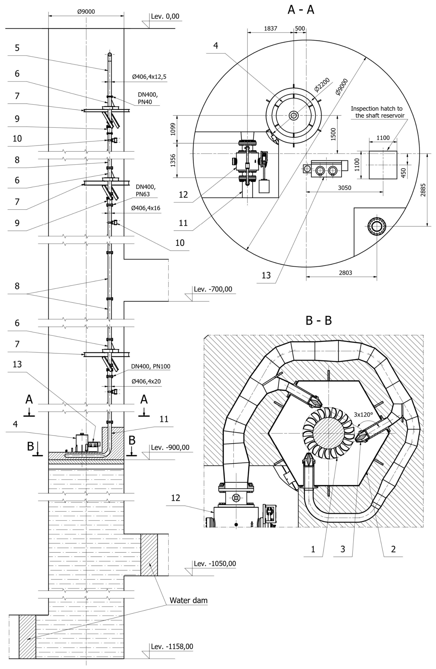
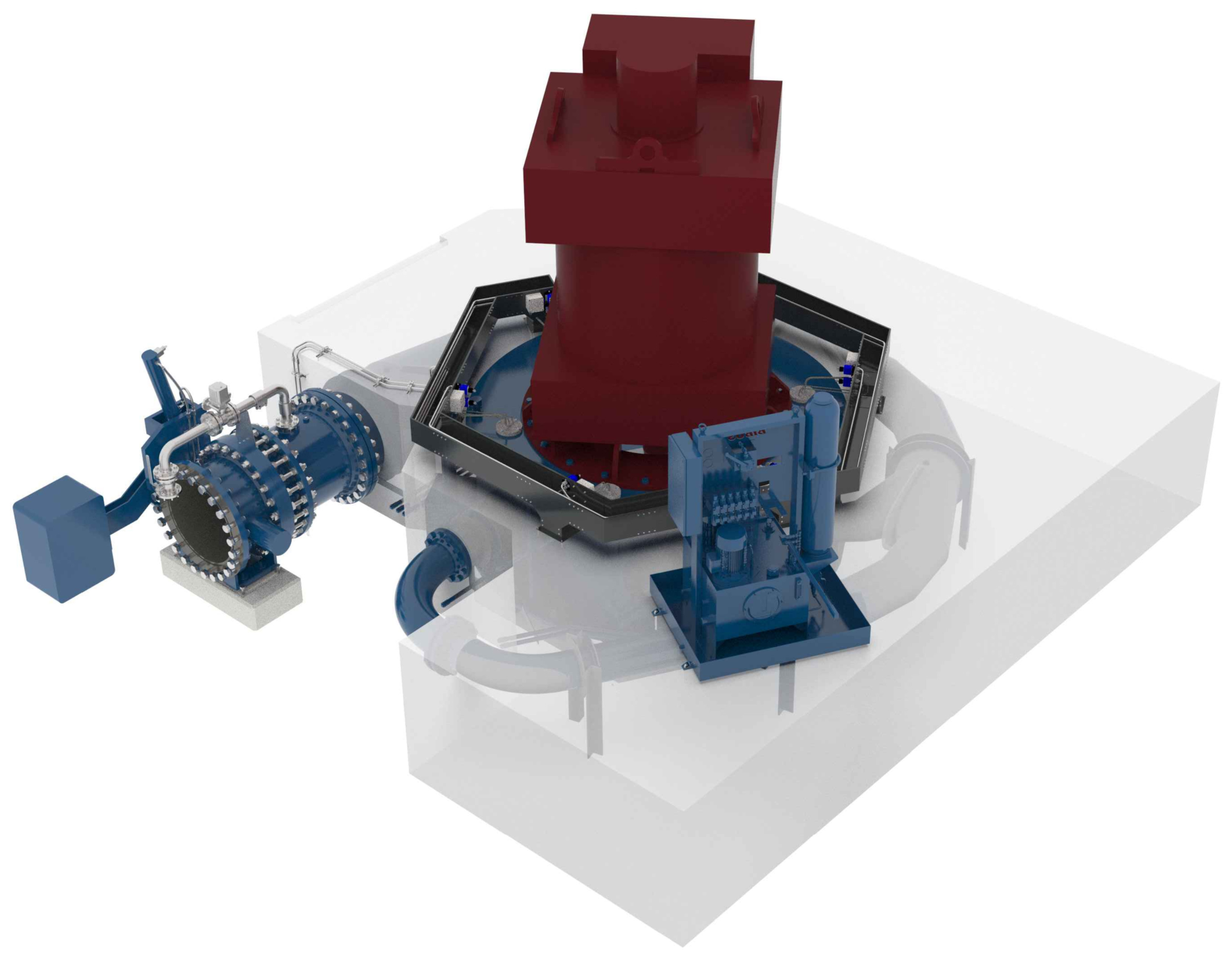
The resulting turbine-generator configuration integrated with the shaft lower reservoir is shown in
Figure 4.
The numbered items in
Figure 4 identify the principal components of the adopted layout: 1—vertical Pelton turbine; 2—turbine housing with distribution manifold; 3—regulating nozzle with jet deflector; 4—synchronous generator; 5—inlet pipe; 6—support pipe; 7—support structure; 8—pipe section; 9—gland-type expansion joint; 10—guiding support; 11—supply pipe; 12—DN400 PN100 ball valve; and 13—hydraulic power unit. Functionally, these components form the energy-conversion, water-conveyance, flow-control, structural-support, and auxiliary-control systems of the generating unit.
The turbine is supplied through an approximately 900 m-long DN400 penstock. The penstock is divided into PN40, PN63, and PN100 pressure zones to account for the increase in hydrostatic pressure with depth. Directly upstream of the turbine distribution manifold, a DN400 ball valve with a design pressure of 100 bar is installed to provide hydraulic isolation of the generating unit. The distribution manifold divides the flow between three internally regulated nozzles arranged symmetrically around the Pelton runner. Needle regulation enables continuous control of the discharge, whereas the corresponding jet deflectors allow the torque acting on the runner to be reduced rapidly without the immediate closure of the nozzles [
15,
16].
The main technical parameters of the adopted turbine-generator unit are summarised in
Table 2.
The preliminary installation arrangement places the turbine-generator unit in the shaft at approximately the −900 m level. The unit is supported by a load-bearing reinforced-concrete foundation structure integrated with the shaft. In the adopted civil-engineering concept, the turbine housing and distribution manifold, together with the terminal section of the DN400 inlet pipeline, are incorporated into the concrete support arrangement. This solution provides stable anchoring, transfers static and dynamic loads to the shaft structure, and limits the transmission of vibrations to the surrounding infrastructure [
15,
16]. The arrangement represents a preliminary integration concept and remains subject to detailed structural and geomechanical verification.
The preliminary installation layout of the turbine-generator unit is shown in
Figure 5.
During generation, water flows from the surface reservoir through the DN400 penstock and turbine inlet valve to the distribution manifold. The flow is divided between three needle-regulated nozzles, which form high-velocity jets directed onto the Pelton runner buckets. The resulting mechanical torque is transmitted directly to the synchronous generator. After passing through the runner, the water is discharged into the lower shaft reservoir, for which a working water volume of 12,000 m
3 was adopted in
Section 3.1.
The turbine output is regulated by changing the positions of the nozzle needles. During transient operating states, including sudden load rejection, an overspeed signal, or a rapid power-reduction command, the jet deflectors first divert the water jets away from the runner. The nozzle needles are then closed gradually, and, where required, the operating sequence is completed by closing the main DN400 ball valve. This sequence rapidly reduces the torque acting on the turbine shaft while avoiding an abrupt interruption of flow in the high-head penstock, thereby limiting pressure surges and the risk of water hammer [
15,
16].
3.3. Lower Reservoir, Hydraulic Isolation, and Underground Service Infrastructure
The lower reservoir is formed within the section of Budryk Shaft II located below the reinforced-concrete machine foundation of the turbine–generator unit. During generation, this reservoir receives water discharged from the Pelton turbine, whereas during pumping, it serves as the water source for the first stage of the return system. The working water volume of 12,000 m
3 adopted in
Section 3.1 was assigned to this part of the shaft and used consistently in the staged pumping-energy assessment presented in
Section 3.4 [
16,
17].
The use of the existing shaft makes it possible to obtain the required lower-reservoir volume without constructing a new underground cavern. It also allows the generating unit and lower reservoir to be integrated within the same vertical structure. However, this configuration requires the existing shaft lining, connections with horizontal workings, installation penetrations, and supporting structures to be adapted to cyclic changes in water level and the resulting hydrostatic loading.
The analysed shaft has a reinforced-concrete lining and an adopted internal diameter of approximately 9 m. Its conversion into a water reservoir requires a detailed condition survey, local repair, or reinforcement where necessary, sealing of joints and penetrations, and the application of suitable protective systems to limit leakage and deterioration of the concrete. Continuous or periodic monitoring of the water level, leakage, lining deformation, and the condition of sealing systems should also be provided [
16,
17].
A quantitative geomechanical analysis performed within the HESS project provides a preliminary reference for the expected response of a reinforced-concrete shaft lining to cyclic internal loading. These results should, however, be interpreted only as a project-level reference case. The applied 2–8 MPa internal-pressure cycle was an idealised loading scenario used in the UDEC analysis and should not be interpreted as the actual hydrostatic pressure history of the Budryk Shaft II lower reservoir, where the pressure acting on the lining would depend on the instantaneous water level and vertical position. Moreover, the numerical model represented one assumed rock-mass structure and stress state rather than a site-specific calibration of Budryk Shaft II. Final verification therefore requires a Budryk-II-specific model based on the actual lining condition, rock-mass discontinuities, in situ stresses, groundwater conditions, and the hydrostatic loading range associated with the adopted operating water levels [
17].
The lower reservoir is hydraulically connected to the turbine discharge zone, whereas the DN400 penstock terminates on the upstream side of the turbine. Consequently, the reservoir lining is subjected primarily to hydrostatic loading associated with changes in the stored-water level, while the considerably higher inlet pressure is carried by the penstock, shut-off valve, turbine distribution manifold, and their anchorage. The interfaces between the shaft lining, machine foundation, penstock penetrations, valves, and turbine structure therefore require separate verification with respect to tightness, stiffness, and load transfer.
The adopted concept requires hydraulic isolation of the horizontal workings and shaft–station connections intersecting the lower-reservoir zone. Water-retaining dams are envisaged at the 1050 m and 1158 m levels [
16]. Their principal function is to separate the water-filled shaft section from the access, service, and pump-chamber workings, prevent uncontrolled water migration, and protect personnel and underground infrastructure against flooding.
At the present stage, the dams were treated as necessary functional and safety components rather than as fully designed structures. Their exact locations, geometry, design pressures, concrete classes, anchorage, and sealing systems must be determined on the basis of the final operating-water levels, the condition of the surrounding rock mass, and the geometry of the individual shaft–station connections. Detailed design should also address foundation preparation, possible rock-mass grouting or reinforcement, permissible leakage, and monitoring of the dam structures.
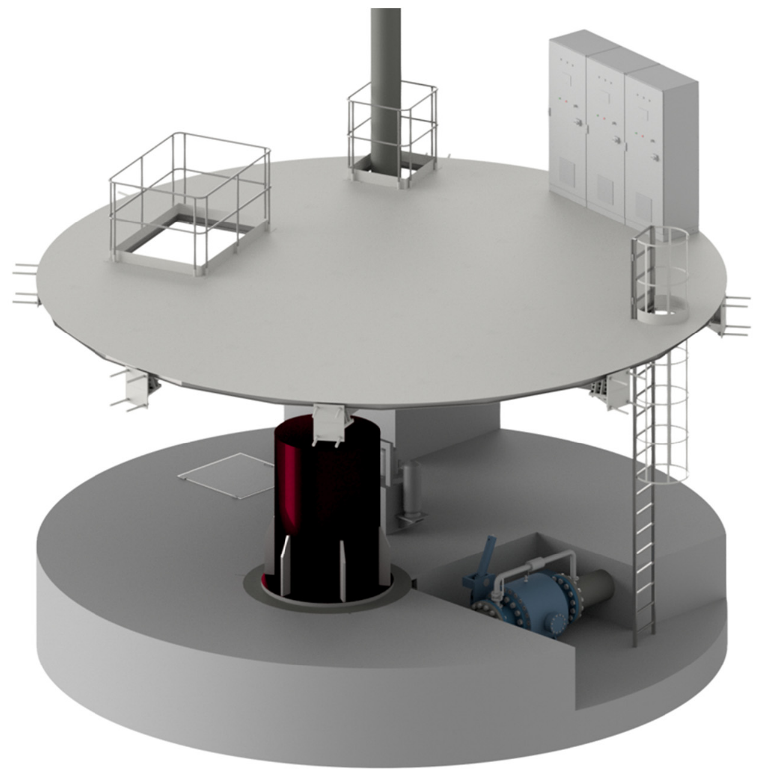
The underground service infrastructure at approximately the −900 m level is required for installation, operation, inspection, and maintenance of the turbine–generator unit and its auxiliary equipment. The initial arrangement comprised upper and lower platform levels, including access to the turbine–generator set, hydraulic power unit, DN400 shut-off valve, control equipment, and inspection areas. The upper steel platform also provides a handling opening and vertical access to the machine level. This preliminary two-level arrangement is shown in
Figure 6.
In the present assessment, the service infrastructure was considered mainly as a spatial, installation, and maintainability constraint. Its detailed structural capacity, anchorage to the shaft lining, access and evacuation routes, handling capacity, and occupational-safety equipment were not independently verified. These elements therefore require further development together with the final arrangement of the turbine–generator unit.
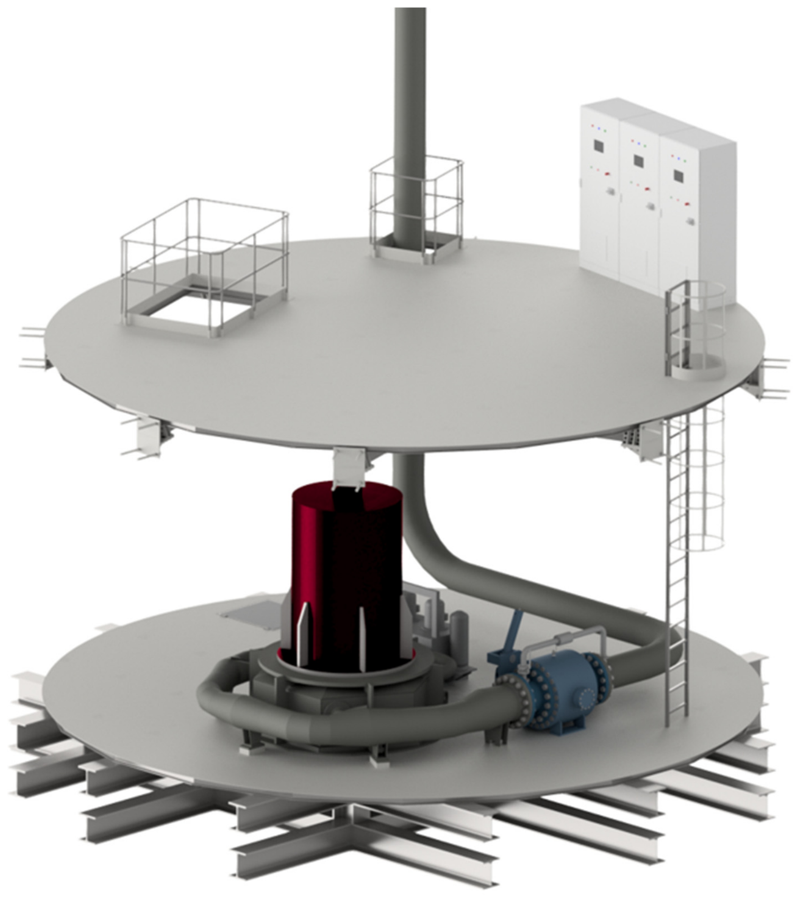
In the original design stage, the lower platform supporting the turbine–generator set was conceived as a steel structure. During subsequent technological review, a massive reinforced-concrete machine foundation was selected as the preferred concept because of the expected static and dynamic loading of the turbine–generator set and the need to limit vibration transmission to the shaft lining and adjacent hydraulic equipment [
16].
Figure 7 presents the original steel-platform arrangement and is retained to illustrate the evolution of the structural concept; it does not represent the foundation solution adopted for the present assessment.
Compared with the original steel concept, the reinforced-concrete foundation provides greater structural mass and stiffness. On this basis, it was selected as the preferred preliminary solution with the expectation of reducing vibration transmission, improving the stability of the turbine–generator alignment, and reducing susceptibility to resonance [
16]. The concept also facilitates anchoring of the turbine housing and associated equipment, load distribution to the surrounding shaft structure, and the incorporation of inspection openings and installation penetrations into the machine-support structure.
These anticipated advantages have not yet been quantitatively verified by a complete structural and dynamic analysis. The final foundation design must therefore include verification of static and transient loads, natural frequencies, damping, turbine overspeed conditions, load transfer to the shaft lining, and interaction with the surrounding rock mass. The reinforced-concrete foundation should consequently be regarded as the preferred conceptual solution and as one of the principal structural constraints governing the underground integration of the generating unit.
3.4. Pumping System from the Lower Reservoir
The return of water from the lower shaft reservoir to the surface is based on a three-stage pumping arrangement using the existing mine drainage infrastructure and intermediate pumping levels. The adopted water-transfer route comprises:
Stage I: pumping from the 1158 m level to the 1050 m level;
Stage II: pumping from the 1050 m level to the 700 m level;
Stage III: pumping from the 700 m level to the surface.
This arrangement enables the water collected in the lower shaft reservoir to be transferred progressively through the existing underground drainage system, as shown schematically in
Figure 3. After reaching the surface, the water would have to be conveyed from the mine water discharge system to the proposed upper reservoir through an appropriate surface-side hydraulic connection.
At the 1158 m level, Stage I is based on four OS-100/5 pumps operating in parallel. Each pump has a nominal capacity of 81 m3/h, a nominal head of 145 m, and a listed nominal power of 47.5 kW. The resulting combined nominal capacity and power of the four-pump arrangement are 324 m3/h and 190 kW, respectively.
At the 1050 m level, the existing pump chamber contains OW-200/7 pumps. For Stage II, the operation of one pump was assumed. Its nominal capacity is 300 m3/h, its nominal head is 420 m, and its listed nominal power is 490 kW. Although additional pumps are available at this level, one unit provides sufficient capacity to accommodate the transfer flow delivered by Stage I.
At the 700 m level, the main drainage pumping station contains pump units equipped with OWH-200/10 pumps or, alternatively, OWH-200M/10Ex pumps. Each OWH-200/10 pump has a nominal capacity of 315 m
3/h, a nominal head of 800 m, and a listed nominal power of 981 kW. The preliminary Stage III calculation assumes the operation of one pump because its capacity exceeds the transfer flow delivered from the lower pumping levels [
19,
22].
The transfer-flow range for the complete pumping route was determined by Stage I, which has the lowest available capacity. An operating range corresponding to 50–80% of its combined nominal capacity was adopted, giving a transfer flow of 162–259.2 m3/h. The same flow range was subsequently assigned to Stages II and III to maintain continuity between the successive pumping stages. This corresponds to estimated pump-load ranges of 54.0–86.4% for the OW-200/7 pump and 51.4–82.3% for the OWH-200/10 pump.
According to Equation (2), for the adopted working water volume of 12,000 m3, the time required to transfer the entire volume through each stage is approximately 74.07 h at a flow of 162 m3/h and 46.30 h at a flow of 259.2 m3/h. These values describe the operating time of each individual stage. The actual elapsed time for returning water to the surface will depend on the available intermediate storage volumes and the extent to which the three stages can operate concurrently.
The operating times and powers were estimated using Equations (2) and (3), respectively. The stage-specific pumping-energy demands were then calculated using Equation (4) from the estimated operating powers and the corresponding pumping times for the adopted working water volume of 12,000 m
3. The resulting values are summarised in
Table 3.
According to Equation (5), the total energy required to transfer the adopted working volume of 12,000 m3 through all three pumping stages is 64.008 MWh, calculated as the sum of 7.037, 19.600, and 37.371 MWh.
The stage-specific pumping-energy demands of 7.037, 19.600, and 37.371 MWh were calculated from the nominal power-to-flow ratios of the adopted pump configurations and the proportional power–flow assumption described in
Section 2.6. They should therefore be interpreted as preliminary calculation-based estimates rather than measured electrical-energy consumption. The simplified model does not explicitly reproduce variations in pump and motor efficiency, hydraulic losses, or deviations of the operating points from the nominal characteristics. Complete pump-performance curves and verified hydraulic-network data would be required for a measurement-validated energy assessment.
The existing mine drainage infrastructure therefore provides a technically plausible route for returning water to the surface, but it was designed primarily for mine dewatering rather than energy-efficient pumped-storage operation. Further design work should include verification of the actual pump operating points, electrical input powers, efficiencies, intermediate-reservoir capacities, coordination between pumping stages, and the hydraulic connection between the mine–water discharge system and the upper reservoir.
3.5. Consolidated Hydraulic and Pumping-Energy Indicators
The preliminary pumping-energy indicators calculated for the adopted assumptions are summarised in
Table 4. The analysis was based on a working water volume of 12,000 m
3 and the calculated energy demand of the three-stage water-return system.
For the adopted working water volume of 12,000 m
3, the total estimated energy required by the three-stage pumping system is 64.008 MWh, as determined in
Section 3.4. This corresponds to a specific pumping-energy demand of 5.334 kWh/m
3 within the adopted calculation boundary.
The calculation covers the transfer of water from the lower shaft reservoir to the surface through the three underground pumping stages. It does not include any additional energy that may be required to convey the discharged mine water from the surface outlet to the proposed upper reservoir. The final system assessment must therefore also account for the layout, elevation difference, hydraulic losses, and pumping requirements of this surface-side connection.
Stage III, extending from the 700 m level to the surface, accounts for approximately 58.4% of the calculated pumping-energy demand. Stage II contributes approximately 30.6%, whereas Stage I accounts for approximately 11.0%. The third stage therefore represents the principal contribution to the calculated demand and should receive particular attention when considering alternative pumps, hydraulic routing, or operating strategies.
The percentage contributions of Stages I–III (11.0%, 30.6%, and 58.4%, respectively) were calculated from the stage-specific pumping-energy demands presented in
Table 3. They represent the allocation of the modelled pumping-energy demand among the three stages and should not be interpreted as a component-level loss breakdown. In the absence of complete pump-performance curves, verified operating points, motor-efficiency data, and hydraulic-network characteristics, pump, motor, frictional, and local hydraulic losses cannot be quantified separately. Because complete pump-performance curves are unavailable, the actual error introduced by the proportional power–flow assumption cannot be quantified directly. An illustrative sensitivity analysis was therefore performed by varying the calculated pumping power, and consequently the pumping-energy demand, by ±20% relative to the baseline estimate. This gives a total pumping-energy range of 51.206–76.810 MWh compared with the baseline value of 64.008 MWh. For the turbine-shaft energy of 24.822 MWh, the corresponding upper-bound energy-return indicator varies from approximately 48.5% to 32.3%. This ±20% range is a parametric sensitivity case rather than a statistically determined uncertainty interval and does not substitute for calculations based on complete Q-H-η-P pump characteristics.
For the adopted working water volume of 12,000 m3 and a turbine discharge of 0.71 m3/s, the theoretical generation time is 4.695 h. Multiplication of this time by the reported rated turbine shaft output of 5287 kW gives 24.822 MWh of mechanical energy at the turbine shaft. Because verified generator-efficiency data were unavailable, the corresponding electrical-energy output could not be determined. Comparison of the turbine-shaft energy with the calculated pumping-energy demand of 64.008 MWh gives an upper-bound single-cycle energy-return indicator of 38.78%. This value is not a verified electrical round-trip efficiency because it compares mechanical shaft output with a calculation-based pumping-energy demand and excludes generator losses, auxiliary consumption, transient operation, and any additional energy required for surface-water transfer.
The single-cycle energy indicators derived in the present study should not be interpreted as an independent economic assessment of the UPSH installation. A separate techno-economic pre-feasibility assessment was completed within the HESS project [
33]. For the PSH subsystem, it estimated a total overnight cost of approximately EUR 64.90 million. Using 2024 Polish Day-Ahead Market prices and the operating assumptions adopted in that assessment, annual PSH electricity consumption was approximately 13.11 GWh, corresponding to an electricity-purchase cost of approximately EUR 0.896 million, while annual electricity production of approximately 7.87 GWh generated an estimated revenue of EUR 1.171 million. The complete economic analysis also included OPEX, NPV, IRR, simple payback time, and LCOE for the two integrated HESS variants. Under the assumptions of that project-level analysis, the NPV values of the two integrated HESS variants were approximately EUR −210.3 million and EUR −193.3 million, respectively, and no finite simple payback time was obtained [
33].
These project-level economic results are not directly transferable to the stand-alone UPSH configuration analysed in the present paper. The techno-economic assessment adopted a PSH production efficiency of 60.01% and an operating schedule of 8 h pumping and 4 h generation within a broader hybrid-system boundary. In contrast, the present study uses a calculation-based pumping demand of 64.008 MWh and an upper-bound turbine-shaft energy of 24.822 MWh for the same 12,000 m3 working volume, corresponding to an upper-bound energy-return indicator of 38.78%. The latter is not a verified electrical round-trip efficiency. A consistent stand-alone economic assessment would therefore require recalculation of the project-level cost and revenue model using the revised energy balance, verified generator and pump performance, auxiliary loads, the complete surface–water transfer requirement and a common system boundary.
The environmental implications should be interpreted with similar caution. A project-level life-cycle assessment of the integrated HESS configurations showed that the reuse of existing post-mining infrastructure can reduce the need for new large-scale underground construction and supports the repurposing of existing industrial assets [
34]. However, the same assessment showed that the climate-change impact is strongly influenced by the electricity consumed during system operation and, under the analysed Polish-grid scenario, is dominated by the fossil-based electricity mix. Consequently, a specific carbon-emission reduction cannot be attributed to the stand-alone UPSH configuration analysed in the present paper without defining an appropriate reference system, electricity-supply scenario, and consistent life-cycle boundary. Likewise, the reuse of the mine shaft may contribute to the broader revitalisation of post-mining infrastructure, but the present study does not provide a quantitative assessment of mine ecological restoration.
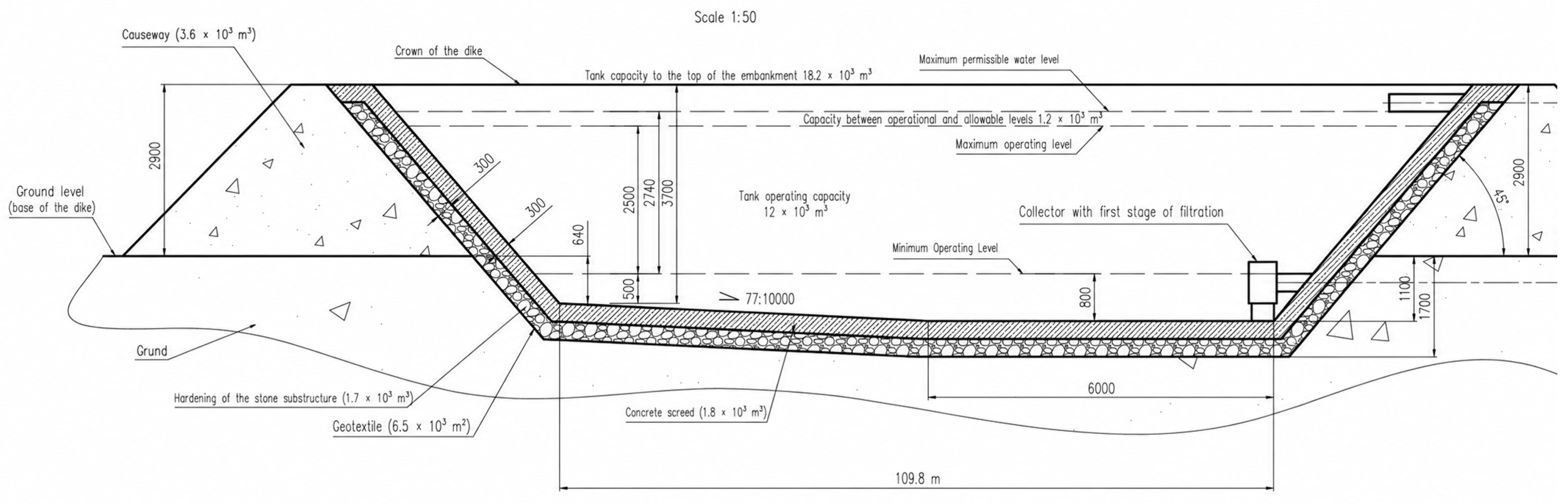
3.6. Upper Reservoir and Water-Intake System
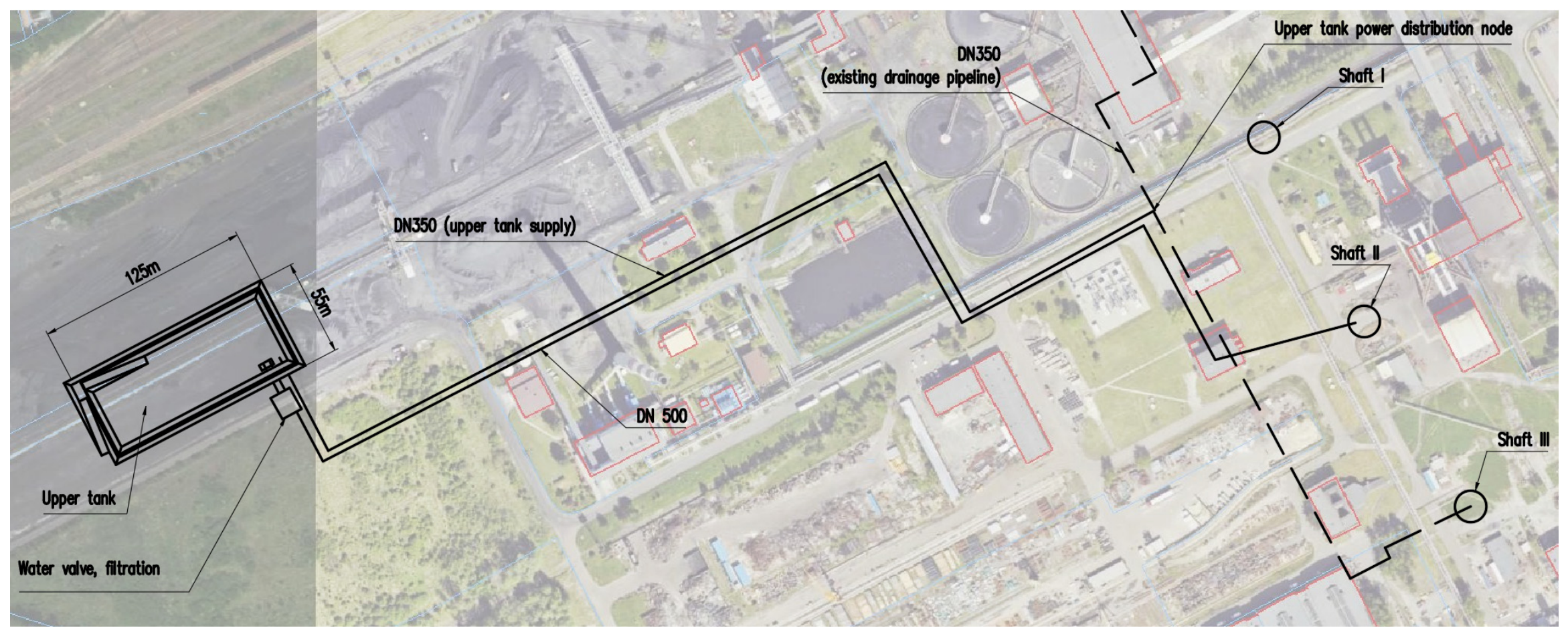
The upper reservoir is located on the surface in the western part of the Budryk coal mine area, next to the stockpile area for coal slurry concentrate No. 3. Its location is shown in
Figure 8.
The upper reservoir was designed as a shallow surface basin with a sealed bottom and slopes, service access, and a water-intake zone directed towards the pressure-pipeline system. In the present assessment, the upper reservoir was considered mainly as the surface storage element required to accommodate the adopted working water volume of 12,000 m
3 and to ensure hydraulic continuity of the system. Its construction details were therefore treated as site-specific design assumptions, while the analysis focused on its hydraulic function within the overall UPSH system. The cross-section of the reservoir is shown in
Figure 9.
The water intake and reservoir supply point are located in the southeastern part of the reservoir. The intake also acts as the first filtration stage for water supplied to the turbine. It consists of a grate and filtration mesh selected to prevent larger solid particles from entering the pressure-pipeline system. According to the adopted turbine-supplier criterion, the maximum permissible impurity size is 12 mm.
Downstream of the intake, the flow is directed through the surface pipeline system towards Shaft II and then to the DN400 shaft pipeline supplying the turbine–generator unit [
16]. In the present study, this arrangement was considered mainly with respect to maintaining the required flow rate, protecting the turbine system against solid impurities, and ensuring hydraulic continuity between the upper reservoir and the underground generation unit.
3.7. Summary of the Resulting System Configuration
At the preliminary design level, the analysed underground pumped-storage concept forms a technically coherent system comprising the following main elements:
a lower reservoir formed within Budryk Shaft II;
a high-head Pelton turbine installed at approximately the −900 m level;
a 6.3 kV synchronous generator with a rated power reported as 5800 kW and a rated power factor of 0.9, directly coupled to the turbine;
a DN400 pressure pipeline divided into PN40, PN63, and PN100 pressure zones;
needle nozzles, jet deflectors, and a hydraulic power unit for flow regulation;
a reinforced-concrete machine foundation and service platforms within the shaft;
watertight dams isolating the shaft reservoir from the horizontal workings;
a three-stage pumping system using intermediate mine levels; and
a surface upper reservoir connected to Shaft II through the water-intake and pipeline system.
The gross design head of 900 m and the corresponding rated net head of 837.81 m provide suitable operating conditions for a high-head Pelton turbine. At the rated operating point, the selected turbine provides an output of 5287 kW at a discharge of 0.71 m3/s.
For the adopted working water volume of 12,000 m3, the preliminary three-stage pumping assessment gives a total energy demand of 64.008 MWh within the calculation boundary extending from the lower reservoir to the surface discharge point. The results indicate that the staged water-return system, particularly Stage III, represents the principal area requiring further hydraulic and energy optimisation before the concept can progress beyond the preliminary technical-feasibility stage.
4. Discussion
The results of the case study indicate that Budryk Shaft II has geometrical and preliminary hydraulic characteristics that support its further consideration as the lower reservoir of a high-head underground pumped-storage hydropower system. The substantial shaft depth provides a gross hydraulic head of 900 m and a rated net head of 837.81 m at the turbine, while the shaft section below the underground machine zone can accommodate the adopted working water volume of 12,000 m3. These findings confirm the geometrical compatibility of the shaft with the proposed arrangement. They do not, however, constitute final confirmation that the complete system is ready for implementation because its feasibility also depends on the pumping system, hydraulic transients, shaft tightness, structural integrity, and integration with the surface reservoir.
The selected generation-side configuration is consistent with the high-head and relatively low-discharge conditions of the site. At the supplier-defined rated operating point, the vertical Pelton turbine provides a shaft output of 5287 kW at a discharge of 0.71 m3/s. For the adopted working water volume of 12,000 m3, the corresponding generation time is 4.695 h, giving 24.822 MWh of mechanical energy at the turbine shaft. The available project documentation reports a synchronous generator rated power of 5800 kW, a rated voltage of 6.3 kV, and a power factor of 0.9, but it does not provide a verified generator efficiency or unambiguously establish 5800 as an apparent-power rating. The electrical energy generated during one cycle therefore cannot be determined reliably from the available data. Because the electrical output must be lower than the turbine-shaft mechanical energy, 24.822 MWh is treated as an upper bound on generated electrical energy. Comparison with the calculated pumping-energy demand of 64.008 MWh gives an upper-bound single-cycle energy-return indicator of 38.78%, rather than a verified electrical round-trip efficiency.
The analysis also demonstrates that the suitability of a post-mining shaft cannot be assessed solely from its depth and available internal volume. This observation is consistent with previous studies indicating that site selection for underground pumped-storage systems must additionally consider the usability and hydraulic behaviour of the underground reservoir, the stability of the surrounding infrastructure, groundwater exchange, hydraulic isolation, and the possibility of adapting existing mine systems to cyclic operation [
23,
24,
25,
26,
27,
28]. In the Budryk case, the use of the shaft itself as the lower reservoir provides a comparatively well-defined geometry, unlike concepts based on extensive goafs or interconnected underground galleries. However, it also concentrates the cyclic hydraulic and structural loads within the shaft lining and at the connections between the reservoir, machine foundation, pressure pipeline, and isolated shaft stations.
The use of a separate pumping system is an unavoidable consequence of selecting a Pelton turbine, which cannot operate reversibly as a pump. The adopted three-stage arrangement provides a technically plausible water-return route using the existing mine drainage infrastructure and intermediate underground levels. This solution reduces the pumping head assigned to an individual pump stage and makes use of infrastructure already available within the mine. Nevertheless, the existing drainage system was designed primarily for mine water removal rather than for repeated and energy-efficient transfer of a fixed working water volume between the lower and upper reservoirs.
For the adopted working volume of 12,000 m
3, the calculated pumping-energy demands are 7.037 MWh for Stage I, 19.600 MWh for Stage II, and 37.371 MWh for Stage III, giving a total of 64.008 MWh. These values are obtained from the nominal power-to-flow ratios of the adopted pump configurations under the proportional power–flow assumption described in
Section 2.6. Stage III accounts for approximately 58.4% of the total calculated demand, Stage II for 30.6%, and Stage I for 11.0%, identifying the transfer from the 700 m level to the surface as the dominant contribution to the calculated pumping-energy requirement.
These stage percentages describe the distribution of the calculated pumping-energy demand and should not be interpreted as a component-level decomposition of energy losses. The simplified model does not separately quantify pump hydraulic losses, motor losses, pipeline-friction losses, or local hydraulic losses. The operating-range diagrams available in the project documentation do not constitute complete pump-performance curves and cannot be used to reconstruct the Q-H-η-P relationships required for a full off-design energy calculation. The ±20% sensitivity case presented in
Section 3.5 therefore illustrates the dependence of the system-level energy result on the assumed pumping power, rather than providing a quantified error bound for the linear approximation.
Such a decomposition would require complete pump-performance curves, verified operating points, motor-efficiency data, and detailed hydraulic-network measurements or modelling. The present calculation also ends at the surface discharge point and excludes any additional energy required to convey water from that point to the final upper-reservoir location.
The calculation boundary is also important for the interpretation of the pumping results. The present estimate covers the three underground pumping stages from the lower shaft reservoir to the surface discharge point. Depending on the final surface–system arrangement, additional energy may be required to convey the discharged water to the proposed upper reservoir. The final assessment must therefore include the elevation difference, pipeline routing, hydraulic losses, required flow rate, and operating strategy of the surface connection between the mine–water discharge system and the upper reservoir.
The project-level techno-economic assessment employed a separate annual operational model and PSH performance assumptions developed for HESS integration and electricity-market analysis. It reported a PSH production efficiency of 60.01%, derived from the annual electricity production and consumption adopted in that model. These assumptions are not directly consistent with the single-cycle pumping-energy calculation presented in the present study, and therefore the corresponding economic indicators cannot be transferred to the stand-alone UPSH configuration without recalculation using a consistent energy-performance basis and system boundary.
Further development of the pumping subsystem should begin with verification of the actual operating points of the OS-100/5, OW-200/7, and OWH-200/10 pumps within the proposed hydraulic network. Particular attention should be given to the compatibility of the capacities of consecutive stages, the required volumes of the intermediate reservoirs, pump-start sequencing, and the prevention of either overflow or insufficient water supply between stages. The analysis should also compare the continued use of the existing mine pumps with alternative arrangements based on pumps selected specifically for cyclic energy-storage operation. Potential improvements include more appropriate pump sizing, variable-speed control, reduction of throttling losses, optimisation of the pipeline route, and consideration of a dedicated water-return system.
The proposed reinforced-concrete machine foundation represents an appropriate preliminary response to the dynamic loads generated by the turbine–generator unit. Compared with the original steel-support concept, the concrete foundation provides greater mass and stiffness, improves alignment stability, and reduces vibration transmission to the shaft infrastructure. However, its final design requires a coupled structural and geomechanical analysis that accounts for static equipment loads, rotational forces, transient hydraulic loads, shaft-lining interaction, and the long-term effects of the humid underground environment.
Shaft sealing and hydraulic isolation remain equally important constraints. The water-filled shaft section must be reliably separated from the horizontal workings by water dams, particularly at the 1050 m and 1158 m levels. The final design of these structures should account for hydrostatic pressure, rock-mass quality, shear resistance, load transfer into the surrounding rock, permissible seepage, and the durability of the sealing materials. Where the surrounding rock is fractured or insufficiently competent, additional grouting, anchoring, or multi-stage retaining structures may be required. The condition of the existing reinforced-concrete shaft lining and the effectiveness of any protective or sealing coating should also be verified before cyclic operation is considered.
Although the use of needle nozzles and jet deflectors provides a technically appropriate means of controlling a Pelton turbine during load changes and emergency shutdowns, the present assessment does not quantitatively verify transient pressures in the approximately 900 m-long DN400 penstock. The preliminary penstock strength calculation nevertheless included an assumed surge allowance equal to 35% of the static pressure, resulting in design pressures of 4.324, 7.549, and 11.919 MPa for the three successive pressure zones. This allowance represents a preliminary design assumption rather than the result of transient-flow modelling. A complete transient-flow analysis is therefore required to determine the pressure changes caused by start-up, load rejection, deflector activation, needle closure, and operation of the main DN400 ball valve. This analysis should be used to verify the PN40, PN63, and PN100 pressure-zone division, valve-closing sequences, support loads, and the need for any additional pressure-control or surge-mitigation equipment.
The repeated filling and emptying of the shaft introduce coupled hydraulic, structural, and hydrogeological risks that have not been quantified at the complete-system scale in the present preliminary assessment. Nevertheless, a quantitative geomechanical reference analysis performed within the HESS project used a UDEC model of a 0.45 m reinforced-concrete lining interacting with a layered-block rock mass under cyclic internal pressures between 2 and 8 MPa. Under the adopted rock-mass structure, material properties, and in situ stress conditions, no crack propagation was observed during the simulated pressure cycles, the lining and surrounding rock mass responded predominantly elastically, and the maximum calculated lining displacement was approximately 10.1 mm. These results provide a preliminary reference for the response of the lining–rock-mass system under the analysed cyclic internal-pressure scenario, but they do not constitute a site-specific verification of Budryk Shaft II. In particular, the 2–8 MPa pressure cycle used in the UDEC model should not be interpreted as the actual hydrostatic loading cycle of the proposed lower reservoir, which depends on the operating water level and vertical position along the shaft lining. The material-level tests performed within the HESS project additionally support the selection of sealing and protective solutions, but they do not replace detailed verification of the complete shaft-lining–rock-mass system. Transient pressures may act together with cyclic changes in hydrostatic loading, while pre-existing cracks, construction joints, service penetrations, and interfaces with the isolation structures may provide preferential leakage paths. A Budryk-II-specific geomechanical analysis based on the actual lining condition, rock-mass discontinuities, in situ stresses, and hydrogeological conditions is therefore required before implementation. The principal remaining parameters and verification activities are summarised in
Table 5.
The preliminary pipeline pressure zoning and the proposed lining, foundation, and dam arrangements should therefore be regarded as conceptual design choices rather than as confirmation of implementation-ready safety. Practical implementation requires demonstration that transient pressures remain within allowable limits, cyclic stresses, and deformations satisfy structural and serviceability criteria over the design life, and leakage remains below a defined permissible value under both normal and emergency operating conditions. The upper reservoir and water-intake system also require further development. The final arrangement must provide hydraulic continuity between the surface reservoir and the underground turbine while limiting the entry of solid impurities into the DN400 penstock and the turbine nozzles. The grate, filtration screen, and any optional basket strainers should therefore be selected on the basis of verified supplier requirements, expected water quality, and permissible hydraulic losses. The completed HESS material tests should be considered together with site-specific water chemistry, suspended-solid content, corrosion potential, scaling tendency, and possible biological contamination when defining the material-selection and maintenance strategy for the complete hydraulic circuit.
Long-term operation should also account for a possible reduction in effective reservoir capacity due to the accumulation of suspended solids, sediment, and deposits within the hydraulic circuit and reservoir zones. The operational and maintenance strategy should therefore include periodic monitoring of water quality and usable reservoir volume, inspection, and cleaning of the intake and filtration system, control of sediment and deposits, and regular inspection of the shaft lining, sealing systems, and hydraulic components for leakage, corrosion, and deterioration.
International research on underground pumped-storage hydropower has progressed from general feasibility studies towards site-selection methods and detailed analyses of underground reservoirs, structural stability, and groundwater interaction, with case studies reported for abandoned mines in China, Spain, and Belgium [
23,
24,
25,
26,
27,
28]. In Poland, research on the energy use of post-mining infrastructure has included the earlier Budryk mine-shaft gravity-storage concept [
8] and mine water hydropower applications [
13]. In addition, the operating profiles and performance characteristics of the conventional Żarnowiec and Porąbka-Żar pumped-storage plants were used within the HESS project as national operational reference points for PSH system analysis; however, these are conventional surface-reservoir installations and should not be regarded as direct analogues of the shaft-based UPSH configuration considered here. These Polish developments demonstrate the potential for energy recovery and storage in underground mine infrastructure, but they differ from the present concept, in which a deep vertical shaft is used directly as the lower water reservoir of a cyclic pumped-storage system. The present Budryk case therefore complements international UPSH studies by examining the integration of a shaft-based lower reservoir, an in-shaft high-head generating unit, and the existing multilevel mine drainage infrastructure within one site-specific configuration.
From a methodological perspective, the principal contribution of the study lies in integrating shaft geometry, lower-reservoir volume, turbine selection, generator nameplate parameters, pressure-pipeline configuration, structural adaptation, hydraulic isolation, and staged pumping within one site-specific assessment. Previous studies have demonstrated the potential use of abandoned mines, goafs, and underground workings for pumped-storage applications [
4,
5,
6,
7,
8,
23,
24,
25,
26,
27,
28]. The present case complements this literature by examining a configuration in which a deep, large-diameter shaft serves directly as the lower reservoir and accommodates the underground generation unit and associated service infrastructure.
The Budryk II case should therefore be regarded as the engineering-assessment stage following an earlier MCDA-based site-screening process rather than as an independently selected case [
14]. Compared with previous screening, reservoir, and economic studies, the transferable contribution of this case study is the explicit treatment of shaft-based UPSH as a coupled system rather than as a storage-potential calculation based only on hydraulic head and available volume. The assessment links reservoir geometry, turbine operating conditions, penstock pressure zoning, hydraulic isolation, and multilevel pumping, thereby identifying the interfaces that control further feasibility. Under the adopted preliminary assumptions, Stage III accounts for approximately 58.4% of the total calculated pumping-energy demand and therefore represents the principal target for further optimisation.
The results should not be generalised directly to other post-mining sites. The feasibility of shaft-based pumped storage depends on the individual shaft geometry, lining condition, depth, accessibility, available mine drainage infrastructure, location of intermediate levels, groundwater conditions, and possibilities for constructing an upper reservoir. The assessment framework may be transferred to other sites, but the equipment selection and resulting technical constraints must be established independently for each location.
Overall, the proposed configuration should be regarded as a coherent preliminary technical concept rather than a verified energy-storage system. The generation-side equipment is compatible with the adopted hydraulic design point, and the shaft can geometrically accommodate the adopted working water volume. The main unresolved issue is the water-return subsystem, particularly the energy demand and operating conditions of Stage III. Before economic performance or complete system efficiency can be assessed, further work is required to verify pump operating points, model hydraulic transients, design the shaft-sealing and water-dam systems, confirm the structural behaviour of the shaft lining and machine foundation, and define the complete hydraulic connection between the surface discharge point and the upper reservoir.
5. Conclusions
This study applied a site-specific preliminary assessment framework to determine whether Budryk Shaft II could be considered for further development as the lower reservoir of a high-head underground pumped-storage hydropower system. The assessment integrated shaft geometry, hydraulic conditions, lower-reservoir capacity, turbine–generator selection, pressure-pipeline configuration, structural adaptation, hydraulic isolation, and staged water return. The results should be interpreted as a preliminary technical assessment rather than confirmation of implementation-ready feasibility.
Budryk Shaft II has a total depth of approximately 1158 m and a diameter of approximately 9 m. For the adopted 200 m high lower-reservoir section, the simplified geometrical volume is approximately 12,720 m3. A working water volume of 12,000 m3 was adopted as the common basis for the pumping calculations. The maximum geometrically available useful head was estimated at approximately 950 m, whereas a gross design head of 900 m and a rated net head of 837.81 m were adopted for the selected hydraulic configuration.
The high-head and relatively low-discharge conditions support the selection of a vertical Pelton turbine. The supplier-defined rated operating point comprises a discharge of 0.71 m3/s and a rated turbine shaft output of 5287 kW. For the adopted working water volume of 12,000 m3, the calculated generation time is 4.695 h, corresponding to 24.822 MWh of mechanical energy at the turbine shaft. Because verified generator-efficiency data are unavailable, the generated electrical energy cannot be determined exactly. Comparison of the turbine-shaft energy with the calculated pumping-energy demand of 64.008 MWh gives an upper-bound single-cycle energy-return indicator of 38.78%; the actual electrical round-trip efficiency would be lower.
The approximately 900 m-long DN400 pressure pipeline, divided into PN40, PN63, and PN100 pressure zones, provides a preliminary means of supplying water to the turbine under the high hydrostatic pressures occurring in the shaft. Needle nozzles, jet deflectors, and the main DN400 ball valve form a technically appropriate preliminary flow-control and shutdown arrangement. However, the effectiveness of this configuration must be verified through transient-flow and water-hammer analysis before the pipeline pressure classes, valve-closing sequence, and support loads can be confirmed.
The adopted three-stage pumping arrangement provides a technically plausible route for returning water from the lower reservoir through the existing mine drainage infrastructure. For the adopted working volume of 12,000 m3, the calculated pumping-energy demands are 7.037, 19.600 and 37.371 MWh for Stages I–III, respectively, giving 64.008 MWh in total. The corresponding stage contributions are 11.0%, 30.6%, and 58.4%, with Stage III representing the dominant contribution and therefore the principal target for further optimisation.
These values are calculation-based estimates derived from nominal pump capacities and powers using a simplified proportional power–flow assumption; they are not operational measurements. The available data do not permit a separate quantification of pump, motor, frictional, and local hydraulic losses. Complete pump-performance curves, verified operating points, motor-efficiency data, and detailed hydraulic-network modelling are required before the electrical pumping demand and complete system efficiency can be validated.
The use of the shaft as a cyclic lower reservoir also requires substantial structural and hydrogeological verification. A reinforced-concrete machine foundation was identified as the preferred conceptual support for the turbine–generator unit because of its mass, stiffness, and vibration-damping capacity. Nevertheless, the final design must account for static and dynamic equipment loads, transient hydraulic forces, shaft-lining interaction, and surrounding rock-mass conditions. Reliable water dams and sealing systems are also required to isolate the water-filled shaft section from horizontal workings, particularly at the 1050 m and 1158 m levels. Before practical implementation, the remaining system- and site-specific parameters listed in
Table 5 must be verified for the intended water-level range, filling and emptying rates, operating-cycle frequency, and design life through transient hydraulic modelling, structural and geomechanical analysis, leakage assessment and an appropriate monitoring programme.
Overall, the assessment indicates that Budryk Shaft II provides a geometrically compatible basis for the proposed high-head underground pumped-storage configuration, and that the selected generation-side equipment is consistent with the adopted hydraulic operating point. The principal unresolved issues concern the performance of the staged pumping system, hydraulic transients, shaft tightness, structural integrity, and the complete connection between the mine water discharge system and the upper reservoir.
Further development should therefore include verification of pump operating points using complete performance curves, optimisation of pump selection and hydraulic routing, measurement or reliable modelling of electrical input power, transient-flow and water-hammer analysis, geomechanical assessment of the shaft lining, detailed design of the reinforced-concrete machine foundation, final design of water dams and sealing systems, and development of the surface hydraulic connection. Further work should validate the preliminary single-cycle energy balance and determine the electrical round-trip efficiency using complete pump-performance curves, manufacturer-confirmed generator efficiency, measured electrical input and output powers, auxiliary-energy demand, and the final hydraulic connection to the upper reservoir.



 ,
,