1. Introduction
Low-grade thermal energy remains one of the largest underutilized energy resources due to weak thermodynamic driving forces and the complexity of conventional heat-engine technologies [
1,
2]. Beyond established renewable energy technologies, increasing attention is being directed toward unconventional approaches that utilize low-grade and widely distributed thermal resources [
3]. A significant portion of primary energy is dissipated as low- or moderate-temperature waste heat, motivating the development of technologies capable of harvesting such diffuse energy streams [
4,
5].
Several approaches have been proposed for converting low-grade heat into useful work. Thermoelectric generators provide direct solid-state conversion [
6], while Organic Rankine and Kalina cycles rely on working-fluid-based thermodynamic processes optimized for low temperature differences [
7,
8]. Despite their maturity, these systems typically require working fluids, pressure vessels, and rotating components, thereby limiting their applicability in small-scale or maintenance-constrained environments. In general, thermoelectric generators offer relatively low conversion efficiency but benefit from compact solid-state operation, whereas ORC and Kalina systems generally achieve higher energy-conversion efficiencies at the expense of increased system complexity associated with working fluids, heat exchangers, and rotating machinery [
6,
7,
8].
Solid-state thermal expansion provides an alternative pathway for harvesting low-grade thermal energy by directly converting the reversible expansion and contraction of structural materials into mechanical work. Existing research on thermoelastic energy harvesting has followed two principal directions. The first direction is based on shape-memory alloys (SMAs), which utilize reversible phase transformations to produce recoverable deformation and mechanical output from thermal cycling. Although SMA-based systems can achieve relatively high energy density, their practical application is constrained by material cost, thermal hysteresis, cyclic durability limitations, and the need for careful thermo-mechanical system optimization [
9,
10]. Recent studies have further demonstrated that the efficiency of thermoelastic harvesters strongly depends on the coupled optimization of material properties, thermal cycling, and system design parameters [
10]. The second direction employs constrained thermal expansion of conventional structural materials governed by classical thermoelasticity and thermal-stress theory [
11,
12]. Within this framework, the present authors previously proposed a column-type actuator that converts reversible thermal elongation into mechanical output through constrained expansion [
13]. However, existing studies have primarily focused on theoretical thermoelastic behavior or individual device concepts, while systematic analysis of modular thermoelastic energy harvesting, including scaling behavior, structural constraints, and techno-economic performance, remains limited. To address these gaps, this study develops a physically consistent modeling framework for modular thermoelastic energy harvesting based on constrained thermal expansion. The proposed framework extends previous device-level concepts by establishing system-level scaling relationships that explicitly account for coupled yield and buckling constraints in modular thermoelastic systems. Specifically, the study makes three principal contributions: (i) formulation of a physics-based framework linking thermoelastic work generation with coupled yield and buckling limits; (ii) derivation of scaling laws governing energy output, active mass, and cost within a modular architecture; and (iii) development of a techno-economic assessment supported by sensitivity and scenario analyses. A key engineering feature of the proposed architecture is the use of sleeve-coupled column segments, which enable scalable assembly while maintaining mechanical alignment and structural integrity.
The remainder of the paper is organized as follows.
Section 2 presents the governing thermoelastic model and its finite-element verification.
Section 3 develops the scaling framework and modular architecture.
Section 4 evaluates structural feasibility and operating constraints.
Section 5 presents the techno-economic assessment and sensitivity analysis.
Section 6 discusses engineering implications and practical positioning, followed by the conclusions presented in
Section 7.
2. Thermoelastic Governing Equations, Structural Limits, and FEM-Based Verification
For clarity and consistency, all symbols, abbreviations, and technical terms are defined at their first occurrence and are used consistently throughout the manuscript and appendices. The proposed concept converts reversible thermal expansion of solids into mechanical work under constrained conditions. The governing behaviour follows classical linear thermoelasticity [
14,
15,
16]. For a uniform temperature change, the free thermal strain is
where α is the coefficient of linear thermal expansion and ΔT is the change in temperature.
When thermal expansion is constrained, the resulting strain generates internal stress.
In the linear elastic regime, the corresponding axial stress is
where E is Young’s modulus. This thermoelastic stress generates the axial force available for mechanical work extraction under constrained conditions [
15,
16].
The admissible force is governed by material strength and structural stability. To ensure elastic operation and adequate fatigue resistance under cyclic loading [
14,
17], the axial force must remain below the yield limit, which depends only on material properties and cross-sectional area. According to Euler’s buckling theory, the critical load decreases with increasing structural length and depends strongly on geometry and boundary conditions [
18,
19]. Beyond this limit, structural response becomes unstable [
20]. The maximum usable force is therefore governed by the more restrictive of the yield and buckling limits, defining a force envelope for thermo-mechanical operation. The available displacement follows directly from thermal strain. For an element of length L, the thermal elongation is
This displacement represents the maximum stroke available per thermal cycle, independent of the specific conversion mechanism.
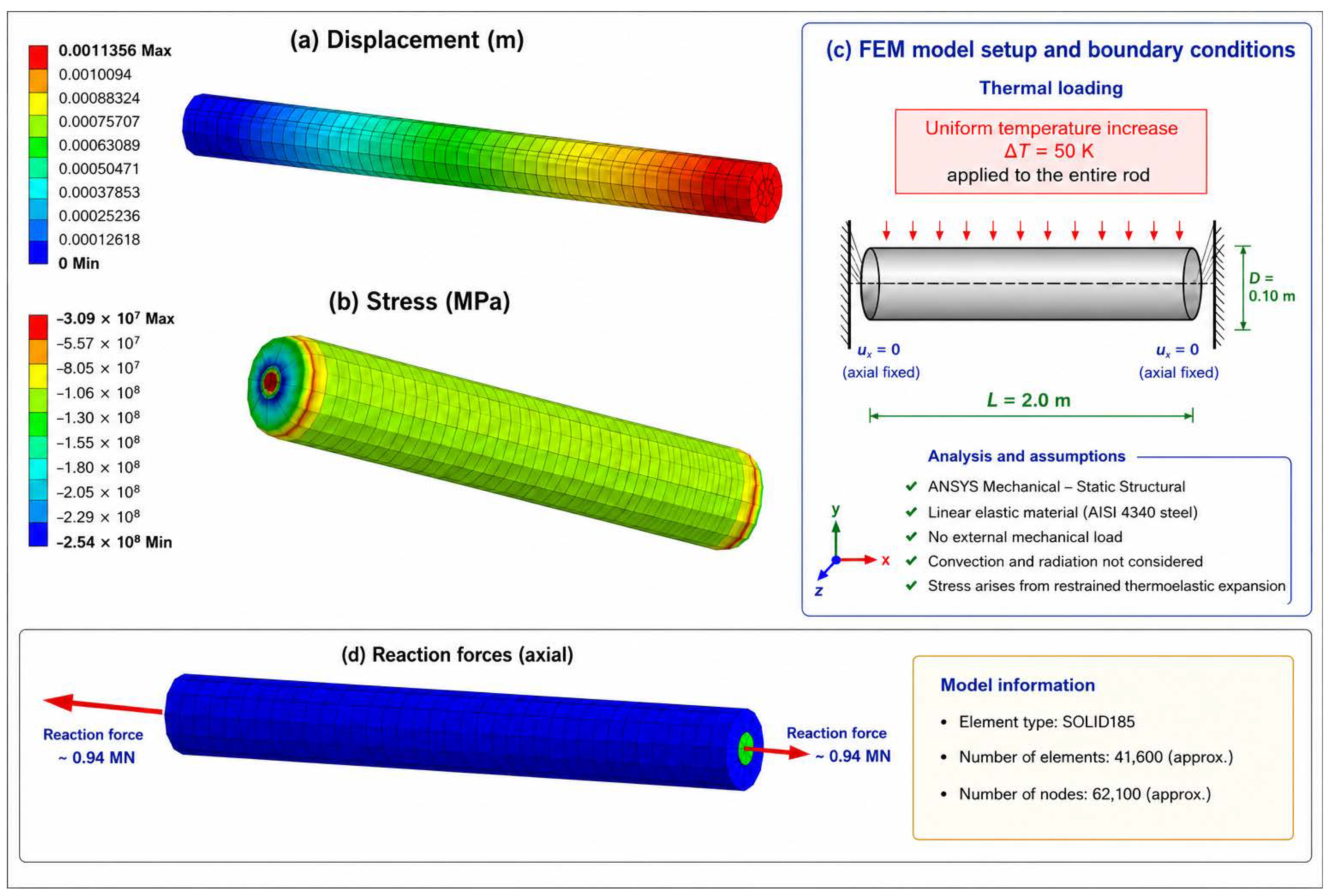
To verify the analytical thermoelastic formulation, a three-dimensional finite element model was developed in ANSYS Mechanical 2025 R2 using the Static Structural solver. A uniform temperature increase was applied to the entire steel rod, corresponding to the prescribed temperature difference adopted in the analytical model. The rod was modelled as an isotropic linear-elastic AISI 4340 steel member. Both end faces were axially constrained to reproduce the restrained thermal expansion assumed in the theoretical derivation. No external mechanical loads were applied, and thermal convection and radiation were neglected. Consequently, the computed stresses arose exclusively from restrained thermoelastic expansion. The objective of the finite-element model was to verify the analytical thermoelastic solution rather than to simulate the complete heat-transfer process. The numerical solution is based on the governing equations of small-strain linear thermoelasticity together with the analytical thermoelastic relations presented in Equations (1)–(3), while detailed derivations are provided in
Appendix A. The corresponding thermal loading, boundary conditions, and reaction forces are illustrated in
Figure 1.
The finite-element results confirm the analytical thermoelastic formulation. As shown in
Figure 1a, the axial displacement increases approximately linearly along the rod length under a uniform temperature increase. The corresponding axial stress remains nearly uniform throughout the rod, with localized stress concentrations near the restrained end faces caused by the imposed axial constraints (
Figure 1b). For E = 210 GPa, α = 11.3 × 10
−6 K
−1, and ΔT = 50 K, Equation (2) predicts an axial thermoelastic stress of 118.65 MPa. The finite element model yielded an average axial compressive stress of 119.3 MPa in the uniform central region of the rod, corresponding to a relative difference of approximately 0.5% from the analytical prediction. This close agreement provides strong validation of the analytical thermoelastic formulation. The equal reaction forces at the restrained ends confirm static equilibrium and the consistency of the imposed boundary conditions. For numerical verification, AISI 4340 steel was selected as a representative high-strength material; the rationale for this material selection is presented in
Section 4.1. The reaction forces shown in
Figure 1d represent the resultant thermoelastic force generated by restrained thermal expansion. Their equal magnitudes at the two restrained ends confirms the expected static equilibrium of the finite element model and provides further verification of the adopted boundary conditions and thermoelastic formulation. The geometry of the finite element model, including the adopted dimensions, thermal loading, axial restraints, and principal modeling assumptions, is summarized in
Figure 1c. At the system level, the admissible thermoelastic force directly determines the upper bound of mechanical work per cycle, linking structural mechanics with system-level energy output. The extractable mechanical work per cycle is fundamentally bounded by the product of admissible force and thermal displacement, establishing an architecture-independent limit on thermoelastic energy conversion. This mechanical constraint forms the basis for the system-level scaling analysis developed in the next section. A detailed derivation of the governing force limits is provided in
Appendix A. The derivation of the work expression and scaling relations is presented in
Appendix B. The theoretical background follows classical stability theory and thermoelasticity [
19,
21].
2.1. Thermodynamic Consistency of Thermoelastic Work Extraction
Although the system is formulated in mechanical terms, its driving mechanism is inherently thermodynamic and requires a time-varying temperature field rather than a uniform thermal state. Mechanical work is generated during both heating and cooling phases. During heating, constrained thermal expansion produces force and displacement, enabling work extraction; during cooling, contraction generates additional displacement in the opposite direction, which can also be utilised. Consequently, the system operates over a complete thermal cycle, rather than relying on a single phase.
The temperature variation may originate from diurnal fluctuations, direct solar heating of exposed elements, or low-grade waste heat, thereby allowing significantly larger temperature excursions than ambient variation alone. From a thermodynamic perspective, the maximum extractable work is limited by the available temperature change and associated heat input [
3]. At the same time, mechanical constraints such as yielding and buckling restrict admissible force and displacement. Consequently, system performance is governed by both thermodynamic and structural limits, with the more restrictive limit determining the attainable output. The thermodynamic implications of these limits are further quantified through efficiency and exergy analysis in
Section 5. The present framework evaluates the theoretical upper bound of recoverable mechanical work under quasi-static thermoelastic loading. Accordingly, the work expression is formulated as an idealized limit based on the admissible thermoelastic force and corresponding thermal displacement. In practice, the recoverable energy may be lower because of transmission flexibility, mechanical compliance, friction, generator coupling, and other irreversible losses. These effects influence the actual conversion efficiency but do not alter the governing thermoelastic force limits or the scaling relationships derived in this study. Their quantitative evaluation requires detailed dynamic system modeling and experimental validation and is therefore beyond the scope of the present physics-based scaling framework. Accordingly, the energy-conversion pathway considered in this study comprises four successive stages: absorbed thermal energy, available thermal exergy, recoverable thermoelastic mechanical work stored as elastic strain energy, and the corresponding electrical energy after mechanical transmission and generator conversion.
2.2. Finite-Element Verification
To verify the finite-element implementation, the numerical results were compared with analytical solutions for a cylindrical steel rod subjected to a uniform temperature increase of ΔT = 50 °C. Two benchmark cases were considered.
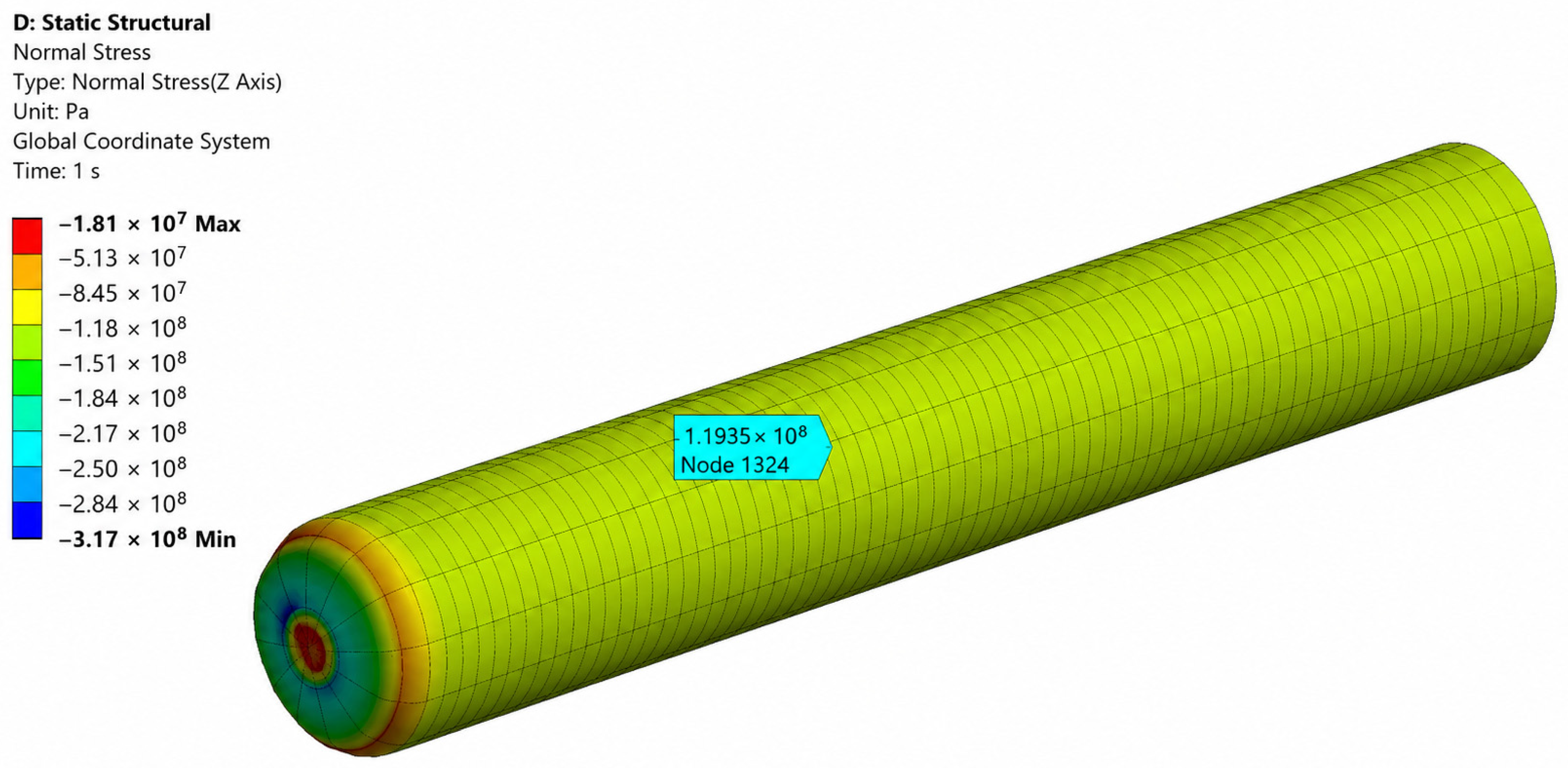
In the first case, both ends of the rod were fixed, resulting in restrained thermal expansion and a nearly uniform axial compressive stress distribution throughout the rod. The maximum compressive stress predicted by the finite element model was 119.3 MPa, which is in close agreement with the analytical value of 118.7 MPa. The corresponding stress distribution is shown in
Figure 2.
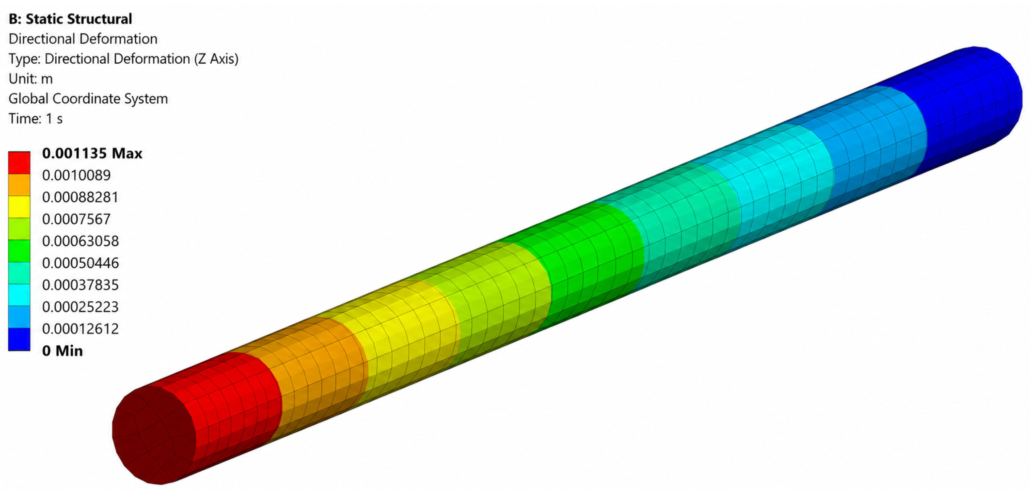
In the second case, one end of the rod was left unconstrained to allow free thermal expansion. The finite element simulation predicted a maximum axial expansion of 1.135 mm, which is in excellent agreement with the analytical prediction of 1.130 mm. The resulting axial displacement field is presented in
Figure 3.
The close agreement between the analytical and numerical solutions confirms the correctness of the finite element model and demonstrates that the adopted modelling assumptions are suitable for the subsequent thermoelastic energy harvesting analysis. The analytical and numerical results are compared quantitatively in
Table 1. The present finite-element model is intended to verify the fundamental thermoelastic response of the proposed concept rather than to simulate the complete modular energy-harvesting assembly. Detailed analyses of sleeve couplings, contact interfaces, cyclic loading, friction, and transmission components are beyond the scope of the present study and are reserved for future engineering optimisation studies.
The relative differences between the analytical and finite-element solutions are 0.55% for the restrained thermoelastic stress and 0.44% for the free thermal expansion, demonstrating excellent agreement and confirming the predictive capability of the proposed analytical model within the adopted assumptions.
The finite-element results presented in this study are validated against the corresponding analytical thermoelastic solutions rather than experimental measurements. Direct quantitative comparison with published experimental studies is not appropriate because the available thermoelastic energy-harvesting concepts generally employ different materials, structural configurations, boundary conditions, and energy-conversion mechanisms. Consequently, the present numerical verification is intended to confirm the correctness of the proposed analytical framework. Experimental validation of the modular thermoelastic architecture using a dedicated laboratory prototype constitutes the next stage of this research and will enable direct assessment of the complete thermo-mechanical and electromechanical energy-conversion process.
The scope of the present numerical analysis should be clearly emphasised. The finite-element simulations presented in this study are intended solely to verify the governing thermoelastic formulation by evaluating the restrained and free thermal response of a representative AISI 4340 cylindrical rod under linear-elastic conditions. Accordingly, the numerical model does not represent the complete modular energy-harvesting system and therefore does not include sleeve-coupled joints, rack-and-pinion transmission, cyclic contact behavior, friction losses, generator dynamics, or electromechanical energy conversion. These components involve additional contact mechanics, structural nonlinearity, and multi-physics coupling that are beyond the objectives of the present physics-based scaling study. Although these components are not explicitly modelled in the present study, they are recognised as important engineering design considerations and will be investigated in detail during subsequent numerical and experimental studies.
3. Scaling Laws and Modular Architecture
The theoretical bounds derived in
Section 2 provide the basis for understanding the scaling behavior of thermo-mechanical energy harvesting systems based on constrained thermal expansion. The extractable work per cycle is governed by the combined influence of admissible force and thermal displacement, leading to two distinct operating regimes: a yield-controlled regime and a buckling-controlled regime [
16,
19]. The transition between these regimes defines a characteristic structural length. For sufficiently long and slender elements, elastic instability dominates because of its strong dependence on structural geometry, whereas for shorter elements, the admissible force is limited by material strength [
19].
To overcome this limitation, a modular architecture is introduced. The system is divided into N identical segments of length lm, such that the total deployed length is the sum of individual modules. By selecting an appropriately short module length, buckling is suppressed and yield-controlled operation is ensured. Under these conditions, the admissible force becomes independent of structural length and is governed solely by material strength. The total displacement remains proportional to system length. As a result, modular segmentation preserves the total thermal stroke while suppressing elastic instability at the element level.
An essential outcome of this analysis is that, once buckling is structurally suppressed, the extractable mechanical work scales linearly with total active length and material cross-section. This establishes an approximately linear scaling of extractable work with system size under yield-controlled operation [
19]. Buckling is therefore a structural, not thermodynamic, limitation and can be mitigated through modular design.
System Architecture and Working Principle
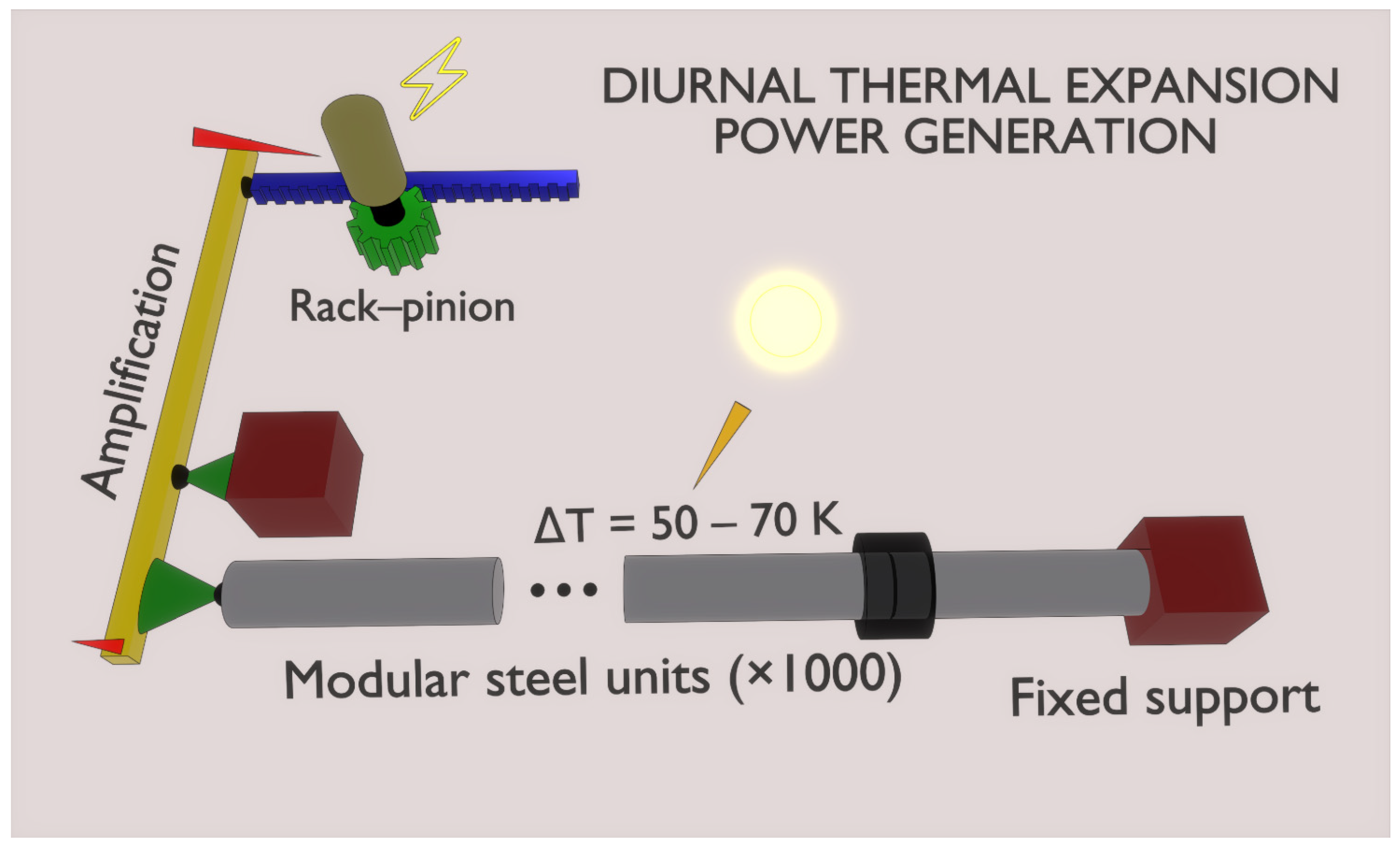
The configuration and operating principle of the proposed system are illustrated in
Figure 4. The system utilises diurnal temperature variations to generate mechanical work through constrained thermal expansion of modular steel elements, consistent with prior thermo-mechanical concepts [
13].
As illustrated in
Figure 4, the system consists of horizontally arranged column modules connected in series and anchored to a fixed support. Thermal expansion and contraction generate axial displacement, which is amplified and converted into mechanical work through a rack-and-pinion mechanism coupled to an electric generator.
The structural elements are implemented as modular segments connected via sleeve-coupled joints, allowing the total length to be adjusted through assembly. The sleeve-coupled joints maintain alignment and stable load transfer across the assembly. Each module undergoes cyclic expansion and contraction in response to cyclic temperature variations (ΔT ≈ 50–70 K). Under constrained boundary conditions, thermal deformation generates internal stress while producing axial displacement, forming the basis of energy conversion. Possible thermal sources, including diurnal fluctuations, solar heating, and low-grade industrial waste heat, are discussed in
Section 2.1. The displacements of individual modules accumulate along the chain and are converted into rotational energy through a rack-and-pinion transmission. One end of the assembly is anchored to a fixed support, whereas the opposite end is connected to a displacement transmission mechanism. This configuration provides partial constraint of thermal expansion, allowing force development while avoiding fully free deformation. The modular design enables scalable increases in total displacement and extractable work while maintaining yield-controlled operation. The primary energy-conversion process relies on solid-state thermo-mechanical deformation and does not require working fluids or thermodynamic cycles.
An important consequence of the proposed scaling formulation is that the obtained scaling laws are geometry-independent once the operating regime has been identified. After normalization with respect to the active structural mass and operation within the yield-controlled regime, the governing relations become independent of the absolute number of modules and depend primarily on material properties, temperature swing, cycle frequency, and conversion efficiency. This generalized formulation allows the derived relationships to be applied to modular systems of different sizes without repeating the structural derivation.
4. Structural Feasibility and Operating Constraints
The scaling relations established in
Section 2 and
Section 3 are meaningful only when the assumed operating regime is physically realisable. In particular, repeated thermoelastic cycling requires verification of yield-controlled operation, thermal response adequacy, fatigue durability, and negligible auxiliary energy consumption. This section defines a physically consistent feasibility envelope using AISI 4340 as a representative high-strength material.
4.1. Material Selection and Module-Level Feasibility
Once elastic instability is suppressed, system performance is governed primarily by material properties and deployed mass. The combined performance index α∙σ
y serves as a first-order indicator of extractable work, but feasibility depends on additional factors including stiffness, cyclic durability, manufacturability, and cost. Structural steels and low-alloy steels (S355, AISI 4140, AISI 4340) offer a favorable balance of strength, stiffness, and cost [
22,
23], whereas aluminum alloys are limited by lower strength and stiffness [
24], and shape-memory alloys by high cost and limited scalability. Material properties are listed in
Table A1 [
18,
22,
24] (
Appendix C).
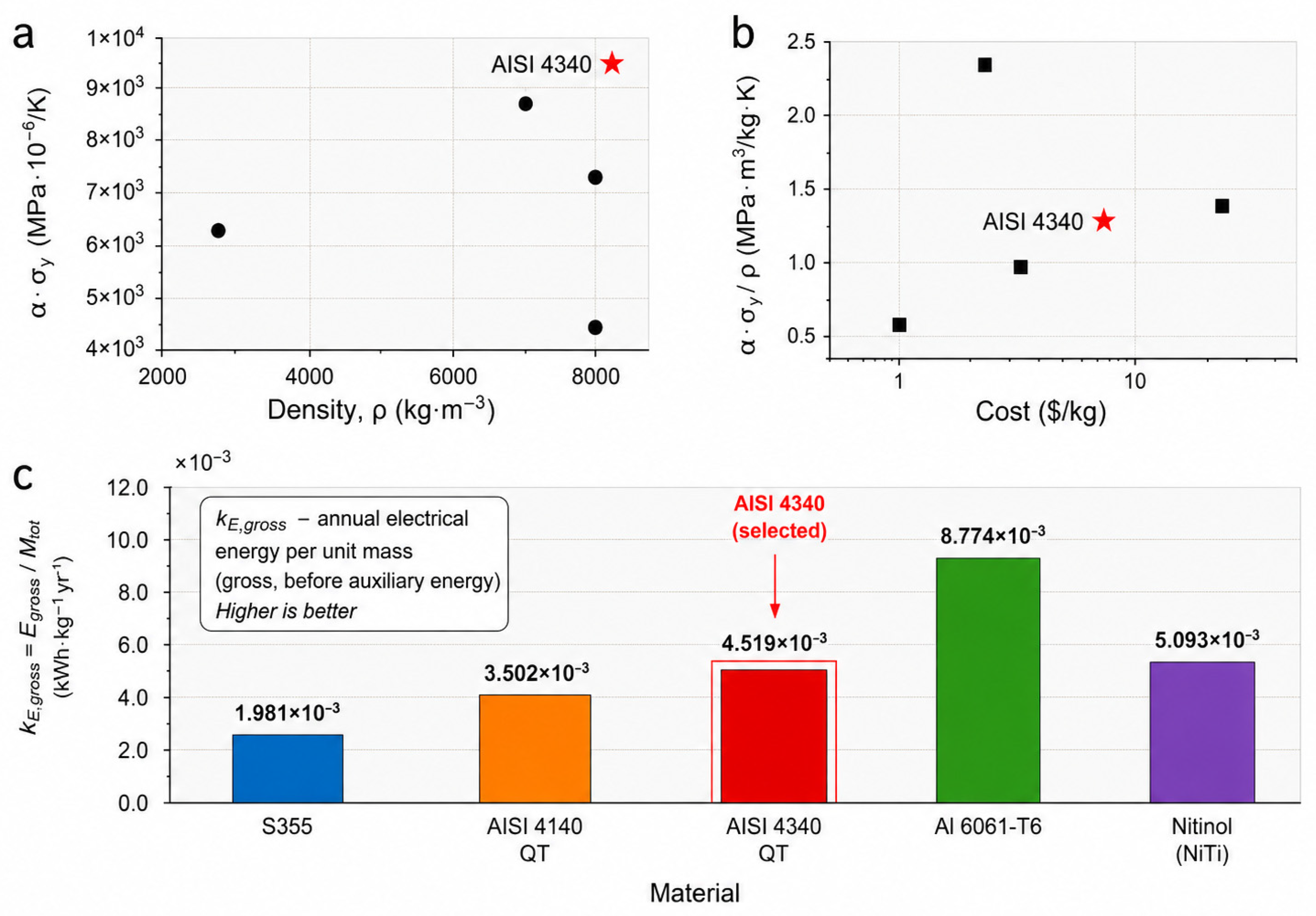
A first-order comparison of performance index values is shown in
Figure 5, where steels occupy a favorable region when performance and cost are considered jointly. Material performance alone is insufficient; stability constraints must also be satisfied. As shown in
Section 3, elastic buckling imposes a geometry-dependent limitation that defines the admissible module length.
Figure 5 illustrates the trade-off between thermoelastic performance and material cost. As shown in
Figure 5a, materials with higher yield strength exhibit a larger thermoelastic strength index (α∙σ
y), indicating greater force-generation capability under constrained thermal expansion. High-strength steels therefore occupy the upper region of the performance map.
Figure 5b further incorporates material cost, revealing a performance–cost trade-off among candidate materials. While some materials achieve high specific performance (α∙σ
y/
ρ), their elevated cost limits practical applicability. To complement the comparative material assessment,
Figure 5c presents the annual recoverable electrical energy per unit mass, calculated using Equations (A15)–(A17). This metric reflects the intrinsic energy-generation capability of each material independently of the module dimensions and depends primarily on the material index (
σy α/
ρ). As expected, Al 6061-T6 exhibits the highest mass-specific energy output because of its low density and relatively high thermal expansion coefficient. However, material selection for thermoelastic energy harvesting cannot be based solely on the mass-specific energy metric. Structural strength, elastic stiffness, buckling resistance, manufacturability, durability, and cost must also be considered. Considering all these criteria together, AISI 4340 provides the most favorable overall engineering compromise for modular thermoelastic energy harvesting systems.
Among the evaluated options, AISI 4340 provides a favourable combination of strength, density, and relative material cost, making it a practical engineering candidate for scalable thermoelastic energy harvesting systems.
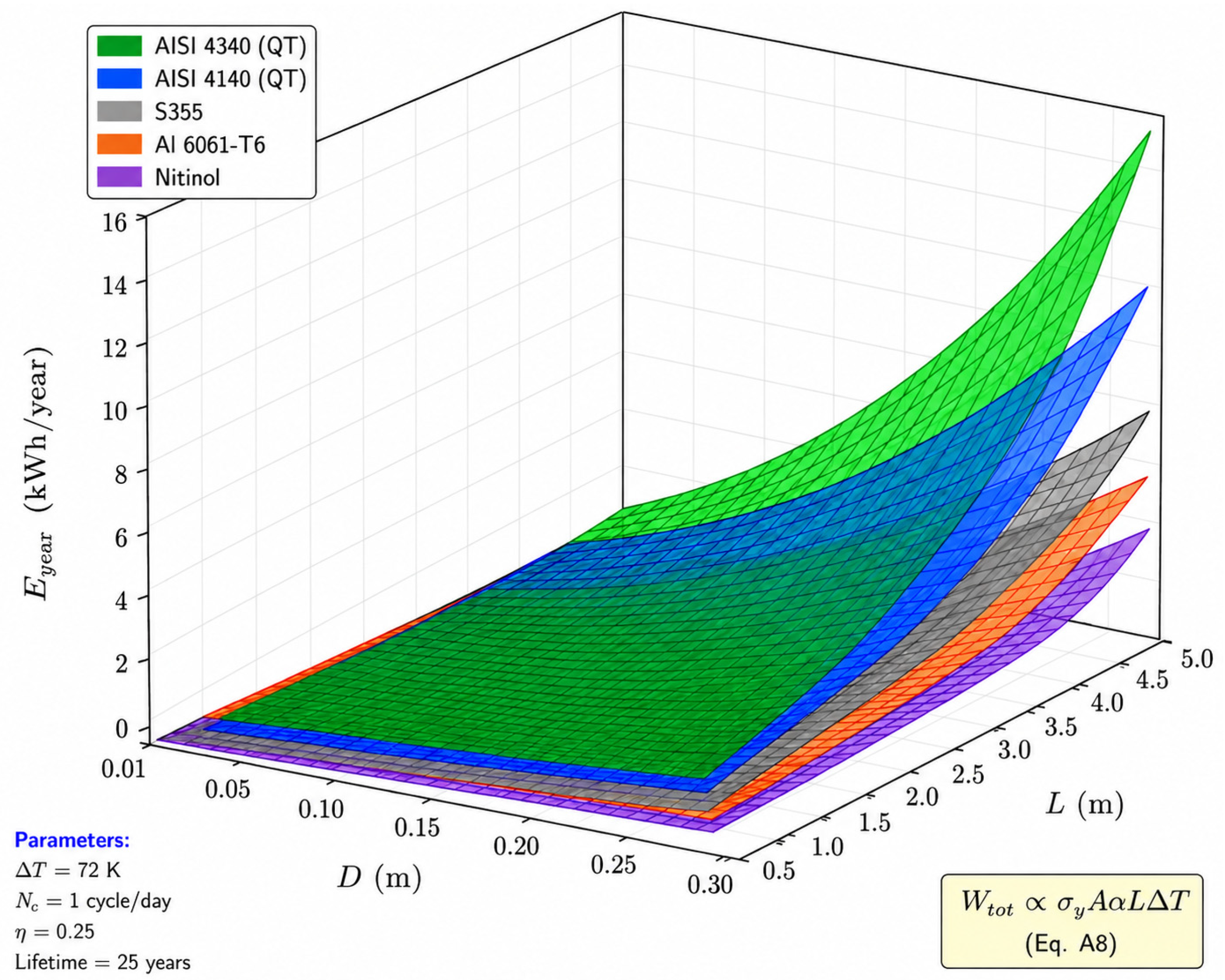
To further illustrate the influence of structural geometry and material properties on the achievable annual energy generation,
Figure 6 presents system-level scaling surfaces for the five representative structural materials over the investigated ranges of module diameter and length. Consistent with the governing scaling law (Equation (A8)), the predicted annual electrical energy increases approximately proportionally with both the active cross-sectional area and module length. Among the investigated materials, AISI 4340 (QT) consistently provides the highest annual energy output throughout the design space owing to its favorable combination of yield strength and thermal expansion characteristics. The figure therefore serves as a practical engineering design map for preliminary material selection and module sizing.
The maximum admissible axial force is governed by the lower of the material yield limit, F
yield, and the Euler buckling limit, F
buckling,
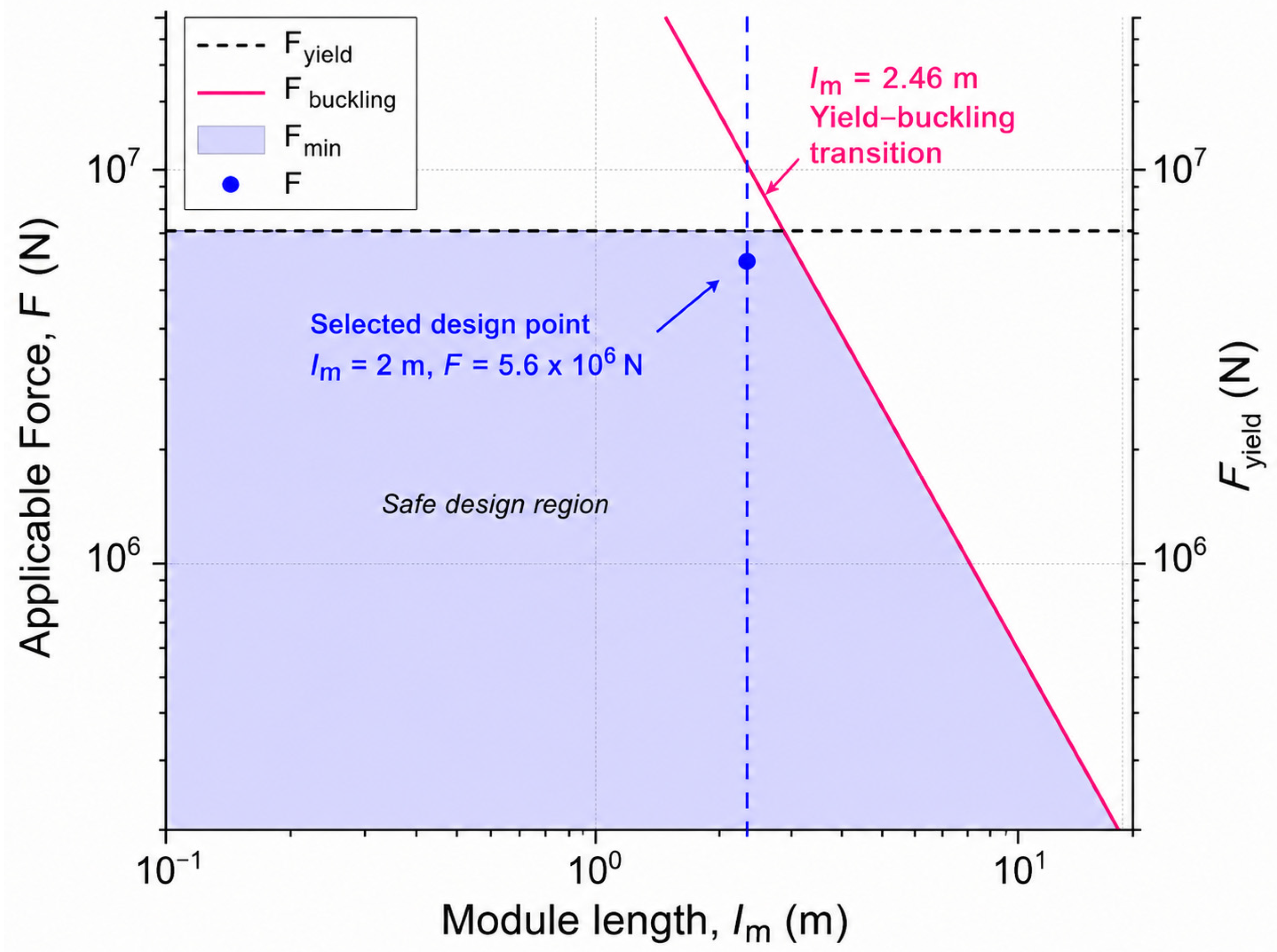
which defines the transition between yield-controlled and stability-controlled regimes and supports the basis for the subsequent parametric analysis. For the selected geometry (D = 0.1 m) and restrained boundary conditions (K = 0.5), the transition between yield and buckling occurs at approximately l
m ≈ 2.46 m. The adopted module length (l
m = 2.0 m) ensures operation within the yield-controlled regime, as indicated in
Figure 7.
As shown in
Figure 7, the intersection of the yield and buckling curves occurs at approximately l
m ≈ 2.46 m, marking the transition between strength-limited and stability-limited behavior. For module lengths below this threshold, the admissible force is governed by material yielding, whereas for longer elements, buckling becomes the limiting factor. The selected module length (l
m = 2.0 m) maintains operation within the yield-controlled regime, avoiding buckling-induced limitations while maintaining a high admissible force level. This result highlights that feasibility is governed by the coupled interaction between material strength, stiffness, and geometry. Structural steels provide a robust design space due to their high modulus and yield strength, whereas aluminum alloys exhibit a significantly reduced feasible domain when stability is enforced.
Figure 7 therefore serves as a regime map that partitions the design space into yield-controlled and buckling-controlled operating regions, providing a practical design criterion for selecting module dimensions.
4.2. Thermal Response, Fatigue Durability, and Practical Operating Conditions
Thermoelastic operation is governed by coupled thermal, mechanical, and operational constraints. The feasibility of multiple daily cycles depends on the transient thermal response of the modules. For the adopted geometry (D = 0.1 m), the characteristic diffusion time is on the order of minutes, indicating rapid internal heat conduction.
The Biot number is estimated as
where L
c ≈ D/4 for a cylinder. For typical values of k ≈ 40–50 W/m∙K and h ≈ 50–100 W/m
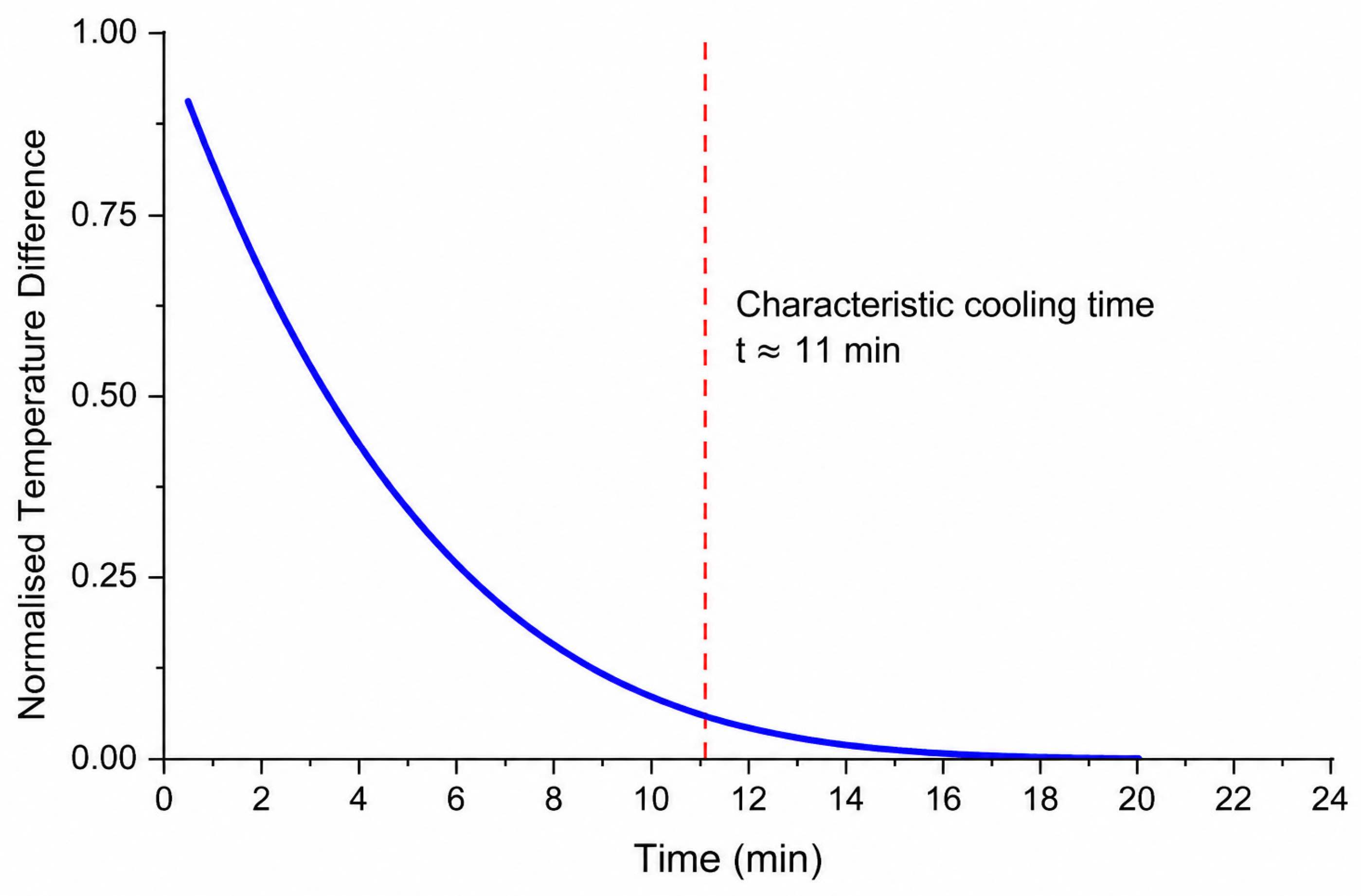
2∙K, Bi remains below 0.1, confirming that internal temperature gradients within the rod are negligible and that lumped thermal behavior is valid. The transient response therefore follows an exponential approach to equilibrium, as shown in
Figure A1 of
Appendix C [
21].
Consequently, multi-cycle daily operation (e.g., N
c ≈ 4) is physically feasible for meter-scale modules, provided sufficient environmental or process-driven heat exchange is available. The value N
c ≈ 4 is considered as an upper-bound illustrative scenario representing enhanced heat-transfer conditions rather than a universal operating assumption. The system operates under long-term elastic cyclic loading. For the adopted 25-year lifetime, the total number of cycles remains within the intermediate fatigue regime for structural steels, even at multiple daily cycles. Fatigue-resistant operation requires that the alternating stress amplitude remains below a fraction of the yield strength, typically in the range of 0.5–0.7 for alloy steels [
14,
25]. Under elastic limits, high-strength steels such as AISI 4340 are expected to sustain the required cycle counts [
14].
For a 25-year lifetime and four cycles per day, the cumulative cycle count is approximately 3.65 × 10
4, well below the very-high-cycle fatigue regime for structural steels. Elastic operation is expected to limit fatigue damage accumulation [
14,
23,
25].
Because internal thermal response is rapid, the dominant limitation on cycle frequency is external heat transfer rather than conduction within the material. Under passive conditions, natural convection and radiation provide sufficient heat exchange for low-frequency operation, while higher cycle frequencies require enhanced heat transfer through environmental exposure or process integration.
Cycle frequency is therefore governed primarily by heat transfer rather than structural constraints. Accordingly, baseline operation assumes no continuous auxiliary energy consumption, and multi-cycle performance reflects utilization of naturally available temperature variations rather than externally driven heating or cooling.
To avoid treating auxiliary demand as universally negligible, three operating cases are distinguished. In the passive case, temperature cycling is driven by ambient variation or existing waste-heat streams, so auxiliary energy is negligible. In the assisted case, low-power airflow or heat-exchange enhancement may accelerate thermal equilibration, and its energy demand must be subtracted from gross output. In the forced case, active heating or cooling can increase cycle frequency, but net output depends strongly on auxiliary consumption. Accordingly, the baseline analysis considers only passive and low-assist operation, whereas forced operation requires a separate net-energy assessment that explicitly accounts for auxiliary energy consumption.
The present fatigue discussion is limited to the global thermoelastic response of the structural members operating within the elastic regime. Local fatigue phenomena associated with threaded sleeve couplings, contact interfaces, stress concentrations, fretting wear, corrosion, manufacturing tolerances, and surface finish were not explicitly analyzed. These effects depend on detailed joint geometry and contact mechanics and therefore require dedicated finite-element contact analysis together with experimental S–N characterization. Such investigations are beyond the scope of the present physics-based scaling study and represent important topics for future numerical and experimental investigations.
5. System-Level Techno-Economic Analysis
This section integrates the structural scaling relations (
Section 2 and
Section 3) with a techno-economic framework based on standard discounted cash-flow methods widely used in energy system analysis [
26,
27].
5.1. System-Level Scaling and Cost Framework
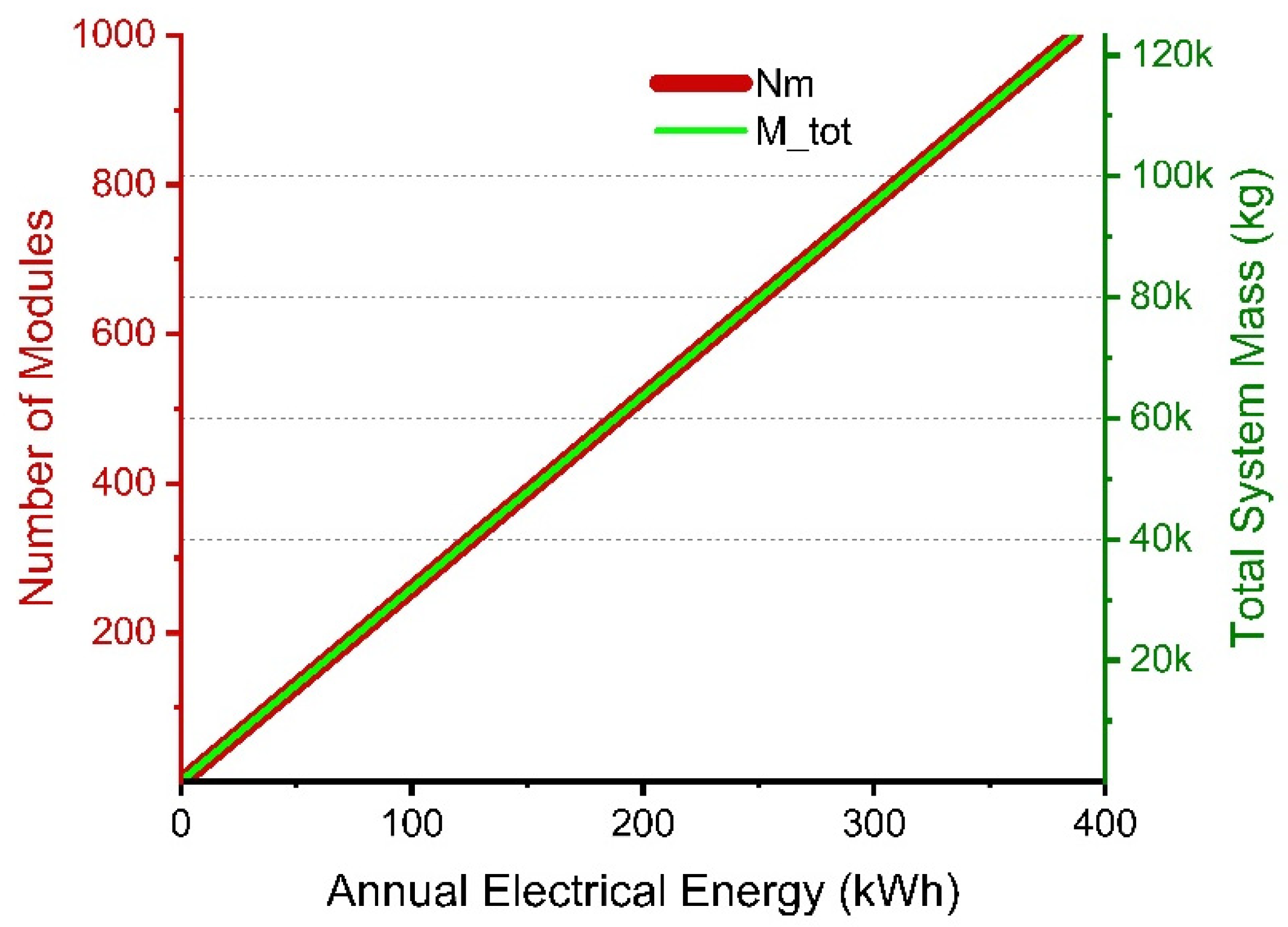
The system-level performance and economic viability are intrinsically linked through the linear scaling of energy output and capital cost with deployed structural mass. For yield-controlled operation, the annual electrical output of the system scales linearly with the number of modules and, equivalently, with total active mass.
Similarly, total system mass scales linearly with the number of modules, leading to a direct proportionality between annual energy output and deployed material mass. In the material-dominated regime, capital cost can be approximated as a linear function of total mass, with an additional constant term representing balance-of-system components. As a result, both annual energy production and capital investment scale linearly with system size [
26,
28]. This linear relationship is illustrated in
Figure 8, which shows a near-proportional increase in energy output with module count and total mass.
The levelized cost of electricity (LCOE) is evaluated using the standard discounted cash-flow framework [
26,
27,
29,
30]. This value reflects a conservative baseline and illustrates the low energy density associated with thermoelastic energy conversion under the adopted assumptions. In early-stage systems with relatively simple mechanical design, operating costs are expected to be small compared to capital recovery and are accordingly neglected in first-order estimates. The baseline LCOE should therefore be interpreted as a first-order engineering estimate rather than a commercial benchmark, since the primary objective of this study is to identify physical scaling limits and design trends rather than to optimize a market-ready energy system.
Under these assumptions, LCOE reduces to a simplified form in which cost is primarily determined by the ratio of material cost to energy produced per unit mass. This highlights a key limitation of thermoelastic systems: the relatively low energy density associated with thermal expansion processes. For the baseline configuration (AISI 4340, D= 0.1 m, L = 2.0 m, ΔT = 72 K, N
c = 1, η = 0.25, lifetime = 25 years, discount rate = 8%), the estimated electricity cost is approximately 10.4 USD/kWh. The assumed material cost (≈0.5 USD/kg) represents an illustrative large-scale structural steel fabrication cost adopted for the present techno-economic case study rather than the market price of specialty alloy steels. The simplified LCOE formulation, together with the case-study equations used for the
Appendix D results, is provided in
Table A2 and
Appendix D.1 [
26,
27,
29]. Additional thermodynamic performance metrics, including heat-input estimation, thermodynamic efficiency, exergy-based assessment, and comparison with the corresponding Carnot limit, are provided in
Appendix D.2.
The present framework is intentionally simplified and is intended for comparative engineering assessment. Site-specific installation costs, maintenance logistics, financing conditions, and application-dependent balance-of-system costs are beyond the scope of the present analysis.
The present LCOE formulation intentionally represents a first-order, material-dominated engineering estimate intended for comparative evaluation of the proposed thermoelastic concept. Additional cost components, including fabrication, sleeve couplings, bearings, rack-and-pinion transmission, electrical generator, installation, maintenance, control systems, and heat-transfer enhancement, were not explicitly modeled because they are highly application-specific and depend on the final engineering implementation. These balance-of-system costs may increase the absolute LCOE but do not modify the governing scaling trends established in this study.
5.2. Sensitivity and Scenario Evaluation
System performance is primarily governed by three multiplicative parameters: cycle frequency, temperature variation, and conversion efficiency. Increasing any of these parameters improves annual energy output per unit mass and reduces LCOE, while coordinated improvements produce a compounded effect [
4,
5,
31,
32,
33].
Baseline and advanced performance scenarios for different combinations are shown in
Table 2. All performance metrics reported in
Table 2 are evaluated using the thermo-mechanical and economic framework defined in
Appendix D.
Specifically, the gross annual electrical energy, Egross, is calculated using Equation (A15), the net annual electrical energy, Enet, using Equation (A16), and the mass-specific net annual energy yield, kE,net, using Equation (A17). The levelized cost of electricity is evaluated using Equations (A18)–(A21). This formulation ensures that all scenarios are evaluated using a consistent analytical and economic framework, allowing direct comparison of the governing parameters. The selected scenarios are not intended to represent successive development stages but rather independent parametric cases illustrating the individual and combined influence of temperature swing, cycle frequency, and conversion efficiency on system performance.
Net electrical output must account for auxiliary energy consumption associated with heat exchange. However, this contribution remains relatively small and does not alter the fundamental scaling behavior. From a thermodynamic perspective, performance may also be evaluated relative to the available thermal exergy. Exergy provides a complementary thermodynamic measure of performance, and the corresponding metrics presented in
Appendix D.2 exhibit trends consistent with those obtained from energy-based indicators. The results summarized in
Table 2 demonstrate that increasing cycle frequency and temperature swing significantly improves performance, while combined optimization produces a compounded improvement because the governing parameters contribute multiplicatively to annual energy generation. In the most advanced scenario (S
3), the estimated electricity cost decreases to approximately 1.1 USD/kWh, illustrating the theoretical upper-bound potential of the concept under favorable operating conditions. The S
3 scenario should therefore be interpreted as an illustrative upper-bound scenario rather than an expected operating condition. The thermodynamic and exergy efficiencies associated with the analyzed scenarios remain substantially below the corresponding Carnot limit, consistent with the limited exergy content of low-grade heat sources. This behavior reflects the intrinsic limits of thermoelastic energy conversion rather than a limitation of the modular architecture.
Importantly, the architecture exhibits strict linear mass scalability: increasing system size raises both energy output and capital cost proportionally. As a result, geometric scaling alone cannot reduce LCOE. These observations provide the engineering basis for the improvement pathways discussed in
Section 6.2. Meaningful cost reduction requires increasing energy extracted per unit mass through improved utilization, higher temperature gradients, and enhanced conversion efficiency.
The sensitivity analysis further indicates a clear hierarchy among the governing parameters. Cycle frequency provides the largest practical improvement because it directly increases annual energy production without increasing structural mass. Increasing temperature swing provides a secondary benefit, although it is constrained by the availability of suitable heat sources and material operating limits. Improvements in conversion efficiency contribute proportionally but remain bounded by the relatively small amount of available thermoelastic work. Consequently, practical performance enhancement should prioritize increased utilization of naturally available thermal cycles before pursuing more aggressive thermal or conversion-system optimization.
Although the present analysis is deterministic, the principal sources of engineering uncertainty arise from variability in material properties (Young’s modulus, thermal expansion coefficient, and yield strength), operating temperature swing, cycle frequency, and practical conversion efficiency. The governing scaling relations indicate that annual energy generation varies approximately linearly with temperature swing, cycle frequency, and conversion efficiency, whereas the admissible thermoelastic force depends primarily on the material properties. Consequently, moderate uncertainties in these parameters mainly affect the quantitative magnitude of the predicted energy output without changing the governing scaling behavior, operating regimes, or the principal engineering conclusions presented in this study.
6. Discussion
6.1. Practical Performance and Energy Density Considerations
Previous studies have demonstrated stable and repeatable force generation under constrained thermoelastic cycling, confirming the physical realisability of the operating principle [
34]. A conservative temperature swing of ΔT = 60 K is considered, representative of typical industrial waste-heat streams (≈80–100 °C source and ≈20–30 °C ambient). A system with 1000 modules (total mass ≈ 1.23 × 10
5 kg) operating at two cycles per day produces approximately 928 kWh/yr (see
Table A2 in
Appendix D). This result highlights the low energy density characteristic of thermoelastic energy conversion and should be interpreted as a quantitative upper-bound estimate rather than a target for commercial deployment. Although modest, the output reflects intrinsically low thermoelastic work density. The system should be interpreted as a distributed solid-state heat-recovery technology rather than a primary power-generation system. The absence of fluids and pressure vessels enables operation where conventional heat engines may be impractical.
System performance is governed by intrinsic thermoelastic work density, independent of geometric scale. Energy output should be normalised by active material mass. For the reference configuration, the net annual energy density is on the order of 0.009–0.018 kWh/kg, consistent with the fundamental limits of elastic strain energy storage. This value is significantly lower than flux-driven renewable systems such as photovoltaics and wind, which are governed by high natural energy flux [
35,
36].
Unlike PV and wind systems, thermoelastic devices rely on internally stored strain energy rather than high natural energy flux. Accordingly, the proposed concept should be interpreted as a structurally integrated, solid-state heat-recovery solution and not as a direct competitor to flux-driven renewable technologies.
6.2. Scaling Implications and System-Level Improvement Pathways
Compared with previously reported thermoelastic energy harvesting concepts, which primarily focus on demonstrating individual thermo-mechanical actuators or material-level behavior, the present work extends the analysis to the system level by establishing analytical scaling laws, identifying the transition between yield-controlled and buckling-controlled regimes, introducing a modular sleeve-coupled architecture, and integrating structural, thermodynamic, exergy, and techno-economic analyses within a unified framework. Rather than proposing a new thermoelastic material or actuator, this study provides a comprehensive engineering methodology for evaluating the physical limits, scalability, and practical feasibility of modular thermoelastic energy harvesting systems. The principal distinctions between representative previous studies and the present work are summarized in
Table 3.
The parameter hierarchy identified in
Section 5.2 provides a practical roadmap for future system development and optimization. The observed scaling behavior defines both the fundamental limitations and the available pathways for system-level performance improvement. The analysis establishes robust system-level scaling laws: both annual energy output and capital cost scale linearly with active structural mass, leading to an LCOE that is approximately independent of system size [
26,
27]. This behavior arises from the fundamental relation between thermoelastic force and displacement, both of which are bounded by material properties and temperature variation. Consequently, increasing system size proportionally increases both cost and energy output without improving energy density.
Meaningful performance improvement must come from increasing energy extracted per unit mass. As shown in
Section 5, this can be achieved through higher cycle frequency, larger temperature variation, and improved conversion efficiency, which act multiplicatively [
32,
33]. Key challenges include fatigue, wear, and thermal-management trade-offs [
25].
Further improvements may be achieved through material optimisation [
37], improved mechanical transmission efficiency and electromechanical energy conversion [
38,
39,
40,
41], enhanced thermal management [
42], lightweight structural design [
43,
44], balance-of-system optimization [
26,
27], and higher utilization of transient thermal gradients [
45,
46]. These conclusions are expected to remain valid irrespective of absolute system size because the governing scaling relations are normalized with respect to active structural mass.
6.3. Positioning Relative to Solar PV and Onshore Wind
Photovoltaic and wind technologies achieve low LCOE due to high natural energy flux and technological maturity [
47]. However, they are optimized for applications characterized by abundant solar or wind resources, whereas thermoelastic systems target fundamentally different operating environments [
48,
49]. The proposed thermoelastic system is not intended to compete with PV or wind in bulk generation. Instead, it targets niche applications characterized by low-grade heat availability, modular deployment requirements, and harsh operating conditions. As summarized in
Table 4, the concept offers a solid-state, structurally integrated alternative with potentially high robustness and low maintenance, but inherently limited by low energy density.
The objective of the comparison in
Table 4 is not to position thermoelastic harvesting as an alternative to utility-scale photovoltaic or wind generation. Instead, the comparison highlights the fundamentally different operating domain of the proposed concept. Thermoelastic harvesting is most suitable where low-grade thermal energy is already available but remains unused, particularly on inaccessible industrial waste-heat surfaces, pipelines, pressure vessels, furnaces, and other high-temperature structural components where conventional renewable technologies cannot directly recover thermal energy. Additional niche applications include structurally integrated self-powered sensing, distributed condition monitoring, remote industrial infrastructure, and auxiliary low-power systems operating in harsh environments requiring high mechanical robustness and minimal maintenance.
This work establishes a physics-based framework for thermoelastic energy harvesting and provides quantitative scaling relations, thermodynamic performance limits, and engineering design guidance for evaluating modular solid-state heat-recovery systems.
The temperature swings and daily operating cycles considered in this study represent scenario-based engineering assumptions rather than predictions for a specific installation. Their practical realization depends on the characteristics of the available heat source, ambient conditions, thermal inertia, heat-transfer coefficients, and the selected passive or active cooling strategy. Consequently, the present results should be interpreted as generalised performance envelopes intended for preliminary system design rather than site-specific performance predictions. Detailed transient thermal analyses using representative industrial heat-source profiles constitute an important subject for future work.
6.4. Study Limitations and Experimental Validation Roadmap
The present study is intentionally limited to a physics-based analytical framework supported by finite-element verification. Although the analytical predictions are internally consistent and the finite-element simulations closely reproduce the governing thermoelastic response, no experimental prototype has yet been constructed. Consequently, practical issues such as transmission compliance, friction losses, backlash, cyclic durability of sleeve couplings, generator matching, thermal contact resistance, and long-term environmental effects remain to be quantified experimentally.
Future work will therefore focus on a staged experimental validation programme. The first stage will involve laboratory-scale verification of thermoelastic displacement, force generation, and recoverable mechanical work using a single constrained modular element under controlled thermal cycling. The second stage will evaluate complete electromechanical energy conversion, including the rack-and-pinion transmission, generator coupling, and electrical output. The final stage will investigate long-term cyclic durability, thermo-mechanical reliability, and field validation under representative industrial waste-heat conditions. These experiments will provide quantitative validation of the analytical scaling laws developed in the present study and support future engineering optimization of the proposed system.
While the baseline fatigue assessment presented in this study evaluates the global elastic cyclic loading of the primary AISI 4340 thermoelastic rod, localized fatigue behavior at critical structural junctions also requires explicit engineering consideration. In particular, threaded sleeve couplings and rack-and-pinion transmission interfaces are expected to represent the most fatigue-sensitive regions because geometric discontinuities and repeated contact loading may generate localized stress concentrations. Consequently, the local fatigue strength of these components may be lower than that of the smooth cylindrical members forming the primary thermoelastic structure. From an engineering perspective, these risks should be mitigated through appropriate thread geometry, generous root radii, high manufacturing quality, suitable surface engineering, effective lubrication of moving contacts, and periodic inspection during service. Although these local mechanisms are not explicitly simulated in the present finite-element model, they are recognized as practical design constraints that must be considered in the engineering design and long-term reliability assessment of modular thermoelastic energy-harvesting systems.
7. Conclusions
This study developed a physics-based framework for modular thermoelastic energy harvesting based on the reversible thermal expansion and contraction of structural materials. The proposed methodology integrates analytical thermoelastic modeling, finite-element verification, thermodynamic assessment, and techno-economic analysis to establish physically consistent performance limits for solid-state energy harvesting from low-grade heat.
The results demonstrate that the maximum recoverable mechanical work is fundamentally constrained by material yield strength, elastic buckling, and the available temperature difference. Modular segmentation enables yield-controlled operation while preserving approximately linear scaling of energy output with deployed structural mass. The finite-element simulations showed excellent agreement with the analytical thermoelastic predictions, thereby validating the governing formulation adopted in this study.
The thermodynamic and exergy analyses indicate that the achievable conversion efficiency remains substantially below the Carnot limit because of the intrinsic characteristics of thermoelastic energy conversion. Consequently, the proposed concept is best suited for applications where structural simplicity, modular scalability, robustness, and low maintenance are more important than high energy density, particularly for recovering low-grade industrial waste heat and other slowly varying thermal resources.
The present framework represents a first-order physics-based assessment rather than a complete engineering design. Local contact mechanics, threaded sleeve couplings, fatigue of mechanical interfaces, transmission losses, and complete electromechanical conversion were not explicitly modeled, while the techno-economic assessment was intentionally formulated as a simplified material-dominated scaling analysis. These aspects require detailed numerical investigation and experimental validation in future work.
Overall, the proposed framework establishes quantitative scaling laws, structural feasibility limits, and engineering design guidelines that provide a foundation for the future optimization, prototyping, and experimental development of modular thermoelastic energy-harvesting systems.




 ,
,