1. Introduction
Coal and gas outbursts are one of the most severe dynamic disasters in coal mining. They directly threaten the safety of underground workers and restrict the efficient and sustainable production of mines [
1,
2,
3,
4]. As mining depth increases, geological structures become more complex, and in situ stress and gas pressure continue to rise. These factors increase the risk of outbursts and the frequency of related disasters [
5,
6,
7,
8]. Meanwhile, the strong heterogeneity and spatial variability of coal seam gas occurrence significantly increase the difficulty of gas control [
9,
10,
11].
Under the condition of close-distance coal seam group mining, mining disturbances caused by working face extraction induce overlying strata movement and structural damage, forming complex fracture systems such as bedding separations and interconnected fractures. After pressure relief in adjacent coal seams, the released gas migrates to the goaf under the action of mining stress and fracture networks, becoming the main source of gas accumulation in the upper corner. Therefore, for working faces mainly affected by gas emission from adjacent seams, arranging high-level gas drainage boreholes has become a key technical measure to control gas concentration in the upper corner [
12,
13]. In recent years, large-diameter directional long-borehole drainage technology has been verified in multiple mining areas.
Cheng et al. [
14] studied the fully mechanized mining face of Huajin Jining Coal Industry in Shanxi Province. By combining numerical simulation, theoretical analysis, and field tests, they revealed the gas drainage mechanism of high-level strike long boreholes in the goaf roof and determined the optimal borehole layout horizon.
Hao et al. [
15] focused on the Wangjialing Coal Mine and determined the optimal layout horizon and borehole structure for large-diameter, high-level directional long boreholes through numerical simulation, which effectively solved the problem of gas exceeding limits in the upper corner. To improve gas drainage efficiency in the goaf fracture zone, Li et al. [
16] proposed a large-diameter roof, directional long-borehole drainage technology. They systematically studied its construction process, reasonable layout horizon, and drainage efficiency. The results showed that this technology has high drainage efficiency and low construction cost.
Based on the actual problem of gas exceeding limits in the upper corner and return airway of the Sihe Coal Mine working face, Chen et al. [
17] determined the layout horizon of large-diameter, high-level directional boreholes in the roof by using empirical formulas and achieved efficient gas control through process improvement. Engineering practices show that arranging high-level boreholes on the auxiliary intake airway side of the working face can effectively regulate the gas flow field in the goaf, inhibit gas accumulation toward the upper corner, and have the advantages of simple construction, low cost, and high efficiency of pressure-relief gas drainage.
The mechanical parameters of each rock stratum were determined based on the geological investigation data and overburden conditions of the mining area, together with representative values reported in previous studies under similar geological conditions [
18]. These parameters were directly adopted in the numerical model without additional calibration.
As summarized in
Table 1, existing studies have employed different approaches for determining the drilling horizon of high-level gas drainage boreholes, including empirical formulas, numerical simulation, engineering practice, and integrated theoretical analyses. Although each method has its own advantages, empirical-formula-based approaches remain widely used because of their simplicity and engineering practicality. However, they cannot fully characterize the dynamic evolution of mining-induced overburden fractures under varying geological conditions. Therefore, an integrated approach combining empirical calculation, numerical simulation, and field verification is adopted in this study to improve the reliability of drilling horizon determination.
2. Mine Overview
The Liuzhuang coalfield is a concealed mine completely covered by unconsolidated overburden. Its main coal-bearing strata include the Permian Shihezi Formation and Shanxi Formation. According to the mine production scheduling, during the mining period of the 1505 mining district working face, some working faces in the upper 8# coal seam district had already completed extraction. As the goaf of the 1505 mining district enters the stages of cave zone collapse and fractured zone development, the rock strata between the 8# and 5# coal seams may experience fracture interconnection, leading to the connection of the goafs of the two coal seams. This process easily allows the gas stored in the 8# coal seam goaf to migrate downward into the 1505 goaf along the fractures. Coupled with the large gas emission from the 5# coal seam itself during the mining of the 1505 working face, the risk of gas exceeding limits at the working face is significantly increased.
Within the West-1 mining district, the inter-seam spacing between the 8# and 5# coal seams ranges from 35.81 to 42.56 m. The 7#, 6#, and 4# coal seams (the latter being close to the 5# coal seam) are developed sequentially between them. The average thickness of the 5# coal seam is 6.32 m. Its upper part is mostly characterized by a massive structure, while its lower part is dominated by a powdered structure. The coal lithotypes are mainly bright coal and dull coal, containing a small amount of vitrain. The lower coal has a higher ash content and weaker luster.
The immediate roof of the 5# coal seam is gray mudstone and sandy mudstone, with a thickness of 0.94 to 13.11 m (averaging 3.61 m). The main roof is fine sandstone, with a thickness of 1.80 to 11.50 m (averaging 3.31 m). The immediate floor is dominated by fine-silt sandstone, locally with interbedded sand-mudstone, and the siltstone thickness is 3.04 to 4.59 m. The main floor is fine sandstone with an average thickness of 11.98 m, and its minerals are dominated by quartz and feldspar, with the upper part locally containing silty components.
3. Coal-Rock Strata Conditions and Model Establishment
In the process of selecting coal and rock seam parameters for numerical simulation, referencing the “Comprehensive Stratigraphic Column and Coal-Rock Strata Correlation Diagram of the 1508 and 1505 Mining Districts,” the parameters for each rock stratum were derived from laboratory tests and references to similar rock block parameters. Based on a comparison with the actual conditions of the coal seam overburden, the finalized rock mechanical properties for the model are shown in
Table 2.
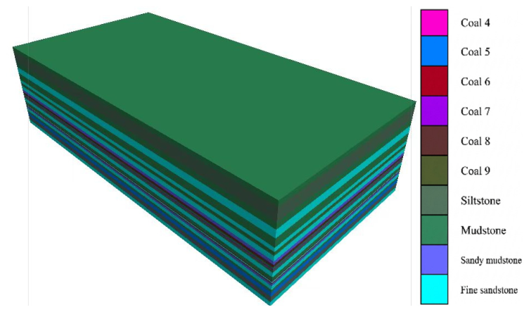
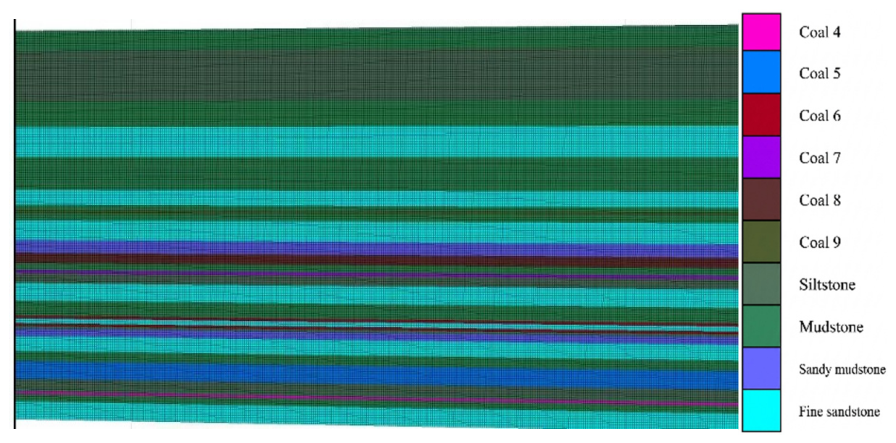
The FLAC3D 6.0 software was utilized to construct a numerical model to simulate the development and evolution laws of mining-induced fractures and to analyze the fracture distribution, deformation displacement, and stress state of the overlying strata under repeated mining conditions. The dimensions of the 3D model established in this study are 600 m × 300 m × 154 m. The coal seams are horizontally bedded, containing six coal seams from 4# to 9#, with the 5# coal seam as the primary research object (
Table 3).
An excavation zone with a width of 100 m was set in the 5# coal seam, advancing along the X-axis direction by 50 m, 100 m, 200 m, 300 m, and 400 m, resulting in five excavation stages. The numerical model was established based on the masonry beam theory, and the Mohr–Coulomb constitutive model was adopted to describe the mechanical behavior of the coal and surrounding rock strata. This constitutive model has been widely used in underground coal mining simulations because it requires only conventional mechanical parameters that can be obtained from geological investigations and previous studies. Since this study focuses on the large-scale evolution of mining-induced overburden deformation and fracture development, the Mohr–Coulomb model is considered appropriate for the present numerical analysis. The Hoek–Brown criterion is more suitable for highly fractured rock masses but requires additional geological parameters (e.g., the Geological Strength Index, GSI) that are unavailable in the present study.
Displacement constraints were applied to the bottom and the X and Y directions of the model, while the Z direction was set as the free displacement direction. Roller support boundaries were applied around the model, and a vertical stress of approximately 15 MPa was applied to the top according to the burial depth of the overlying strata. The mechanical parameters of each rock stratum were determined based on the geological investigation data and overburden conditions of the mining area, together with representative values reported in previous studies under similar geological conditions. These parameters were directly adopted in the numerical model without additional calibration. The established numerical models are shown in
Figure 1 and
Figure 2. To minimize the influence of model boundaries, the excavation panel was arranged near the center of the numerical model, leaving sufficient surrounding rock around the excavation area. The selected model dimensions are consistent with those commonly adopted in similar numerical studies of underground coal mining.
4. Simulation Results of Mining-Induced Fracture Evolution
4.1. Vertical Displacement Laws of Mining-Induced Roof
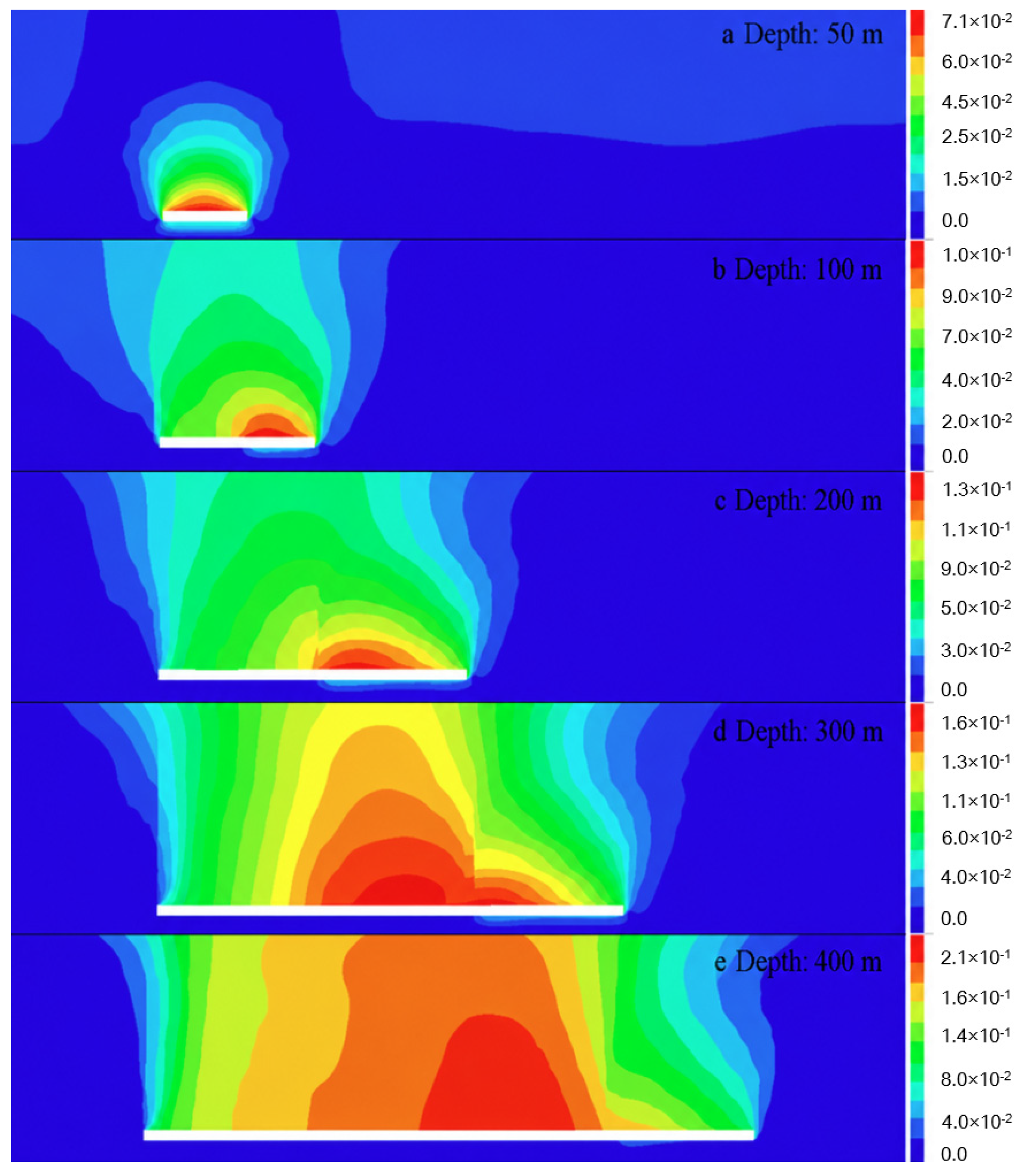
To study the evolution laws of vertical displacement and vertical stress in the goaf overburden, the vertical displacements of the mining-induced roof at different advancing distances were monitored. The vertical cross-sectional displacement contours obtained from mining the 5# coal seam are shown in
Figure 3. According to the results shown in
Figure 3, during the extraction of this coal seam, the overlying strata cave and undergo vertical displacement, and the primary affected zone exhibits an approximately trapezoidal distribution in space. As the advancing distance of the coal seam mining increases, the displacement of the overlying strata shows distinct stage characteristics. As shown in
Figure 3a, when the 5# coal seam mining advances to 50 m, the mining disturbance to the overlying strata is limited, and the scale of the displacement zone is small. As the working face continues to advance, the displacement zone gradually expands along the mining direction. The mining influence is mainly concentrated in the rock strata directly above the coal seam, while the impact on the lateral rock mass is relatively weak. In addition, along the mining strike direction, the roof displacement contours show an asymmetric distribution. The peak displacement points generally shift toward the open-off cut side, and this phenomenon remains consistent across different horizons of the rock strata. The results indicate that the working face support system not only maintains the stability of the rock mass inside the stope but also exerts a significant restrictive effect on the displacement distribution of the adjacent surrounding strata. In terms of the quantitative development of displacement, both the affected range and the magnitude of roof displacement increase with the mining advancement. When the advancing distance is 50 m, the maximum roof displacement is 0.07 m. When advancing to 400 m, the maximum displacement increases to 0.21 m, representing a threefold increase, which demonstrates a clear distance effect. Overall, the vertical displacement increased progressively with the advancement of the working face, accompanied by the continuous expansion of the deformation influence range. The maximum displacement occurred above the center of the goaf, where the overburden experienced the most significant subsidence. These results indicate that the deformation field evolved continuously during mining and reached a relatively stable distribution after sufficient face advancement.
4.2. Vertical Stress Laws of Mining-Induced Roof
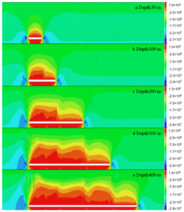
To reveal the dynamic evolution laws of vertical stress during the extraction of the 5# coal seam, this study conducted a systematic quantitative and qualitative analysis by plotting the vertical stress distribution contours at different mining advancing distances, as shown in
Figure 4. The analysis shows that the mining activities of the 5# coal seam break the original stress equilibrium of the overlying and underlying rock strata in the stope, leading to stress redistribution. Distinct stress concentration occurs in the coal and rock mass both ahead of and behind the working face, while a significant pressure-relief effect appears within the goaf area, with the pressure-relief scope gradually expanding as the working face advances. After coal seam extraction, the vertical stress of the overlying strata decreases significantly, forming a pressure-relief zone with an approximately trapezoidal shape. This zone continually develops and expands along the mining direction, and its boundary shape closely corresponds to the mining advancement trajectory. With the progress of mining, the vertical stress variations in the goaf roof strata are relatively small, whereas a stress concentration zone persistently occurs near the open-off cut, and the degree of concentration gradually intensifies with mining advancement. When the mining advancing distance is 50 m, the maximum vertical stress in the stress concentration zone is approximately 27.2 MPa. When advancing to 400 m, this value increases to 28.7 MPa, representing an increase of about 5%, which reflects a continuous stress accumulation effect at the open-off cut during long-term mining.
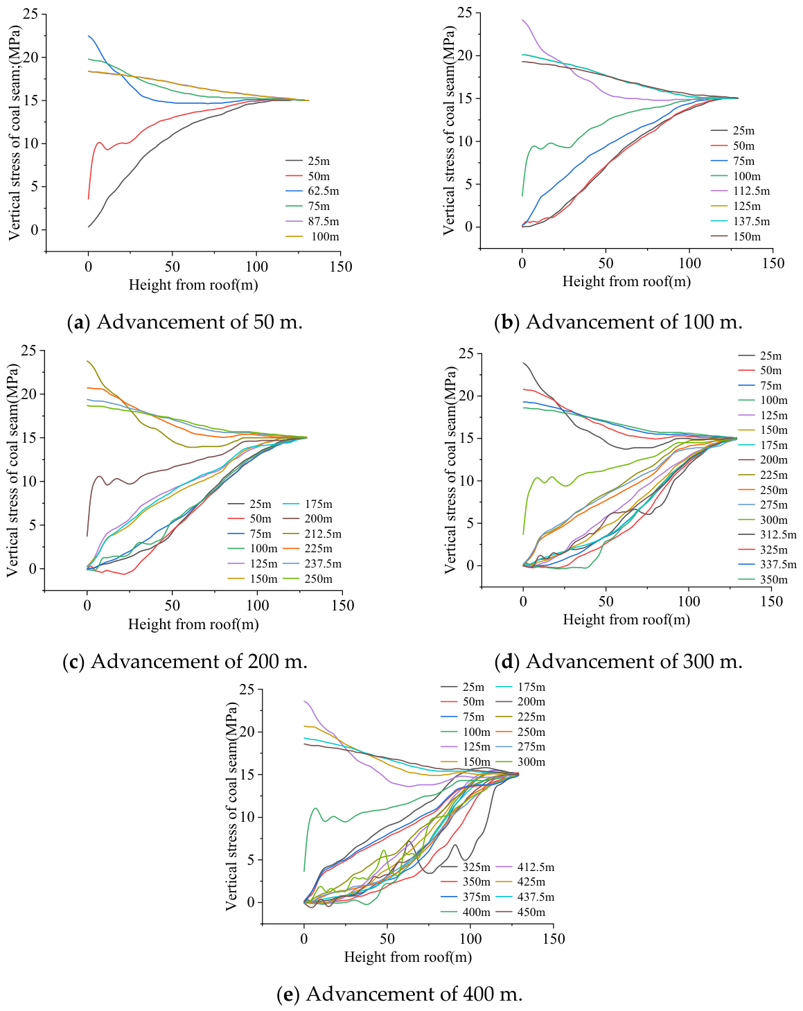
To accurately monitor the stress distribution laws, vertical stress monitoring lines extending from above the roof to the top of the model were arranged at different positions from the open-off cut, as shown in
Figure 5. The results show that based on the characteristics of stress variations, the stress distribution at different distances can be divided into three typical zones: directly above the roof, near the terminal mining line, and ahead of the goaf. Within the zone ahead of the goaf, four monitoring lines were deployed with a spacing of 12.5 m. The analysis indicates that the mining distance has a relatively limited impact on stress in this zone, and each monitoring line presents a basically consistent trend of stress variation, generally showing a gradual increase in stress from the top of the model toward the roof. Notably, the stress variation at 12.5 m ahead of the goaf is the most significant, reaching the highest peak stress of approximately 24 MPa, which indicates a distinct stress concentration phenomenon in this area. Meanwhile, the stress curves at 25 m, 37.5 m, and 50 m ahead of the goaf exhibit a high degree of overlap, further demonstrating that the scope of stress influence tends to be consistent in the far field. The stress variations near the terminal mining line display a similar law and are minimally affected by the mining distance. The stress in this zone generally decreases as the height above the roof decreases, dropping sharply at a height of 6 to 8 m, with the minimum stress value reaching approximately 3 MPa. Furthermore, monitoring lines were arranged with a spacing of 25 m in the zone above the roof; the stress response in this zone varies complicatedly with the mining distance but presents an overall decreasing trend, reflecting the pressure-relief effect of the roof strata under mining disturbance.
4.3. Fracture Evolution Laws of Mining-Induced Roof
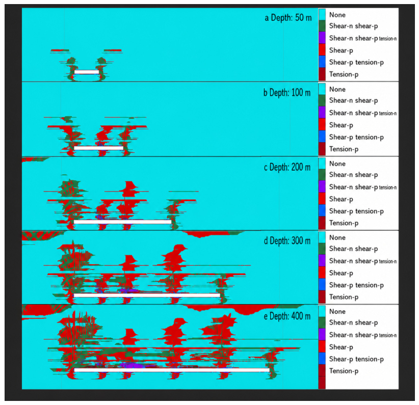
Under the continuous action of mining disturbances, the stress field of the goaf overburden exhibits characteristics of periodic adjustment. The periodic caving process of the roof prompts the gradual formation of a well-connected fracture network in the rock mass above the goaf, providing key channels for gas migration and accumulation. To achieve the goal of efficient gas drainage, large-diameter boreholes must be accurately arranged in the gas enrichment zones within the overburden fractured zone. The core of reasonably determining the horizon of large-diameter boreholes lies in systematically analyzing the dynamic development laws of mining-induced overburden fractures during working face advancement (see
Figure 6) and carrying out scientific design of borehole positions based on this.
Based on the dynamic evolution characteristics of the rock plastic zone during working face advancement, the damage degree of rock strata can be identified. Rock failure modes can be mainly divided into four categories: shear-p, shear-n, tension-p, and tension-n (where “p” represents the past damage state and “n” represents the current damage state). According to the results shown in
Figure 6, during the extraction of the 5# coal seam, the plastic zone of the rock strata presents a continuous expansion trend, and the spatial morphology of the roof plastic zone stably exhibits a “spoon-shaped” distribution. Affected by the supporting effect of the working face support system, the damage degree of the rock mass close to the working face side is significantly lower than that on the open-off cut side. This difference primarily stems from the fact that the rock mass on the open-off cut side is long exposed to a periodic cyclic stress environment accompanied by a significant pressure-relief effect, resulting in a much higher accumulation of damage than that on the working face side, which in turn causes the center of the plastic zone to shift toward the open-off cut side. Regarding the spatial distribution of failure types, the outer boundary of the plastic zone is dominated by shear failure, reflecting that the stress state in this area is dominated by shear stress. Tensile failure mainly occurs around the goaf, which is closely related to the tensile deformation of the rock mass induced by goaf pressure relief.
Coal seam extraction initially triggers the initiation of fractures in the overlying strata, and their developmental characteristics exhibit a stage-wise evolution law with increasing advancing distance. As the 5# coal seam working face advances from 50 to 400 m, the damage evolution of the overlying strata demonstrates significant spatiotemporal heterogeneity and a transition in mechanical mechanisms. In the initial mining stage (50 to 100 m), the failure zone is primarily concentrated near the immediate roof of the coal seam. During this stage, affected by mining-induced unloading, the direction of the maximum principal stress rotates, leading to stress concentration at the goaf boundaries, while the central roof enters a pressure-relief state.
As the mining advances to 200 m, the damage mechanism transitions to a tension-shear composite mode. The damage scope expands significantly into the upper rock strata, with the maximum damage height reaching 5 to 6 times the mining height. Interlayer bed separation becomes more pronounced, forming multiple bed-separation fracture zones. A large amount of past shear damage (shear-p) begins to emerge, indicating that some zones have experienced shear slippage and tend toward stress relaxation. Current shear damage (shear-n) is mainly distributed on both sides of the goaf and beneath the high-level key strata, reflecting the shear stress concentration effect at the boundary of the stress shell. The rock mass failure in this stage is not only controlled by tensile action but also significantly influenced by shear slippage and structural plane activation, forming a step-like failure structure with certain self-organizing characteristics.
Upon entering the large-scale mining stage of 300 to 400 m, the overlying strata gradually develop a typical “three-zone” structure consisting of the caving zone, fractured zone, and continuous deformation zone. The damage contours illustrate extensive shear damage in the high-level rock strata, indicating that the far-field rock mass has entered a plastic state and undergone significant shear slippage, with the damage height extending to 8 to 10 times the mining height. Meanwhile, tensile damage continues to develop above the central goaf, indicating that a dynamic deformation process still exists in the lower part of the continuous deformation zone. Overall, the rock strata damage evolves from a localized, single failure mode in the early stage to a global, composite failure system.
This evolutionary process profoundly reveals the spatiotemporal evolution law of mining-induced rock mass failure: tensile fracturing dominates the shallow rock mass, whereas shear slippage governs the deep rock mass. Current damage propagates forward as the working face advances, reflecting a spatiotemporal dynamism, while past damage records the cumulative and permanent process of rock mass failure. According to the degree of rock strata damage, the overlying strata can be divided into the caving zone, fractured zone, and continuous deformation zone. Combining the roof failure morphology after the extraction of the 5# coal seam with the model dimensions and using the plastic zone distribution as the primary criterion for determining the roof failure height, the zones can be preliminarily quantified based on the deformation degree: the region below 12 m above the coal seam belongs to the caving zone, and the maximum development height of the fractured zone can reach 60 m.
The simulated plastic zone exhibits a typical spoon-shaped morphology, which is consistent with the overburden failure characteristics reported in previous numerical simulation studies of longwall coal mining. The progressive upward expansion of the plastic zone with increasing advancing distance indicates the continuous development of mining-induced fractures and provides a reliable basis for identifying the caving zone and fractured zone. Therefore, the plastic zone distribution can reasonably reflect the evolution characteristics of the overburden failure process.
In this study, the identification of the spoon-shaped fracture structure was mainly based on the spatial distribution characteristics of the plastic zone, including its upward extension above the goaf and lateral expansion toward both sides. It should be noted that a unified quantitative criterion for describing the geometric characteristics of mining-induced fracture zones has not yet been established. Therefore, the present study focuses on the evolution trend and spatial distribution characteristics of the fracture zone, while detailed geometric quantification requires further investigation.
5. Theoretical Calculation of Overlying Strata Failure
By investigating the field measurement data of caving zone and fractured zone heights from multiple domestic working faces and through systematic correlation and analysis, the empirical formula applicable for calculating the maximum height of the caving zone after thick coal seam extraction was derived as follows [
19]:
where
Hm is the height of the caving zone,
m; and
M is the thickness of the mined coal seam,
m.
The empirical formula applicable for calculating the maximum height of the fractured zone after thick coal seam extraction is as follows:
where
Hli is the height of the fractured zone,
m, and
M is the thickness of the mined coal seam, m.
By substituting the parameters into the formulas, respectively, the maximum height of the roof caving zone is calculated to range from 8.77 to 34.5 m, and the maximum height of the roof fractured zone ranges from 75.36 to 89.34 m. Through a comparative analysis of the maximum heights of the “two zones” obtained from the numerical simulation and the empirical formulas, it can be concluded that the numerical simulation results differ slightly from the calculation ranges of the empirical formulas; however, the discrepancy is minor, and the two methods can mutually validate each other.
Although direct in situ observations of fracture-zone geometry were unavailable, the numerical simulation results were indirectly validated by both the empirical calculation of fracture-zone height and the satisfactory field gas drainage performance. It should be noted that the lack of independent monitoring data, such as borehole imaging or geophysical detection of fracture-zone boundaries, remains a limitation of the present study. However, the consistency between numerical results, theoretical calculations, and gas drainage performance provides reasonable support for the proposed drilling horizon optimization. Future studies will incorporate more direct monitoring techniques to further verify the spatial evolution of mining-induced fracture zones.
6. Determination of Horizons for Large-Diameter Directional Boreholes
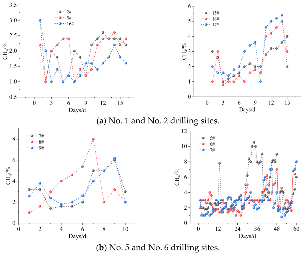
Cross-stripping boreholes were arranged at different heights above the roof of the 5# coal seam to monitor the gas concentration. The No. 1 drilling site was located 15 m above the roof of the 5# coal seam, the No. 2 and No. 5 drilling sites were at 20 m, and the No. 6 drilling site was situated at 25 m. Based on the actual gas drainage data from the cross-stripping boreholes in the mine (see
Figure 7), further analysis reveals distinct differences in the gas drainage concentrations across different drilling sites. The gas concentration at the No. 1 drilling site was generally below 3%, the lowest among all sites; the gas concentrations at the No. 2 and No. 5 drilling sites were at a medium level, with peak values ranging between 5.5% and 8%; the No. 6 drilling site achieved the highest concentration, reaching approximately 11%. This indicates that arranging large-diameter directional boreholes at a position 25 m above the roof can realize high-concentration gas drainage.
It should be noted that the field monitoring data available in this study mainly included comparative gas concentration records, while other statistical indicators such as average extraction rate and cumulative methane production were unavailable. Therefore, the comparison of drilling horizons was conducted based on the available gas concentration data combined with numerical simulation results and geological conditions.
Furthermore, considering the controlling effect of key strata and the lithological mechanical conditions of the roof [
18,
20], the movement of the overlying strata during the extraction of the 5# coal seam is primarily controlled by a 7 m-thick fine sandstone key stratum located 24 to 31 m above the roof. This layer possesses a stable structure and continuous distribution, playing a dominant role in the deformation of overlying strata and fracture development. Arranging the borehole horizon near this key stratum can, on the one hand, efficiently intercept the rising gas from the working face and increase the drainage concentration; on the other hand, the key stratum exhibits strong deformation resistance, which can significantly reduce the risks of mining-induced borehole shear failure and mid-section gas leakage, ensuring that the borehole mouth always remains within the effective drainage range behind the goaf. Concurrently, this rock stratum features high stability and favorable mechanical properties and is not prone to collapse or deformation, meeting the requirements of borehole formation technology. This is conducive to mitigating the risk of borehole wall instability and ensuring the long-term effectiveness of the drainage engineering.
Although direct in situ observations of fracture-zone geometry were unavailable, the numerical simulation results are indirectly validated by both the empirical calculation of fracture-zone height and the satisfactory field gas drainage performance.
From an engineering application perspective, the optimization of the drilling horizon can reduce the uncertainty associated with borehole layout selection and avoid ineffective drilling arrangements in unsuitable locations. Although a detailed economic analysis was not conducted due to the lack of complete field cost data, the proposed method has potential economic benefits by improving the utilization efficiency of directional boreholes and reducing unnecessary drilling operations. In addition, the improvement of gas drainage effectiveness can contribute to reducing gas accumulation risks and enhancing mining safety.
7. Conclusions
(1) The failure and damage of the overlying strata during working face advancement demonstrate remarkable stage-wise characteristics and spatial distribution laws. The plastic zone generally exhibits a “spoon-shaped” distribution, with the damage being more concentrated on the open-off cut side. Numerical simulations indicate that the height of the overburden caving zone is approximately 12 m, and the maximum development height of the fractured zone can reach 60 m, presenting a distinct stratified structure controlled by the key strata. The mechanical stability of the key strata plays a dominant role in determining the development scope and interconnectivity of the fractures.
(2) The drainage performances of boreholes at different horizons vary significantly. Specifically, the boreholes arranged at the 25 m horizon achieve the highest gas drainage concentration of up to approximately 11%, which is markedly superior to that of the boreholes at the 15 m and 20 m horizons. These results fully demonstrate that the zone near the key stratum possesses the comprehensive characteristics of well-developed fractures, significant gas enrichment, and highly continuous seepage channels, identifying it as the optimal placement interval for high-efficiency gas drainage via large-diameter directional boreholes.
(3) This study reveals the development height and distribution characteristics of mining-induced overburden fractured zones by integrating theoretical analysis, FLAC3D numerical simulations, and field measurement data, which finalizes the optimal layout range for the high-level boreholes in the 5# coal seam of Liuzhuang Coal Mine to be between 24 and 31 m. The research findings effectively address the ambiguity of borehole horizon selection under the conditions of contiguous extra-thick coal seam groups, providing a reliable scientific basis for gas control and safe, high-efficiency mining at the Liuzhuang Coal Mine working faces.
The proposed drilling horizon was determined based on the geological conditions of the 150,502 working face in Liuzhuang Coal Mine. Therefore, it is primarily applicable to mining areas with similar geological and mining conditions, while its applicability under different geological settings requires further investigation. In addition, the optimized drilling horizon is expected to improve the effectiveness of gas drainage by locating boreholes within the most developed fracture zone, thereby contributing to safer and more efficient coal mining.