Article

Power Control for Hybrid Isolated Micro-Grids: A Three-Level Converter-Based Experimental Approach

by
Moussa Gaptia Lawan
1,
Ahmed Al Ameri
1,2,*,
Mamadou Baïlo Camara
1 and
Brayima Dakyo
1
1
Groupe de Recherche en Electrotechnique et Automatique du Havre (GREAH), EA3220, Université Le Havre Normandie, 76600 Le Havre, France
2
Electrical Department, Faculty of Engineering, University of Kufa, Najaf 54001, Iraq
*
Author to whom correspondence should be addressed.
Energies 2026, 19(14), 3350; https://doi.org/10.3390/en19143350
Submission received: 24 May 2026 / Revised: 2 July 2026 / Accepted: 11 July 2026 / Published: 16 July 2026

Abstract

An advanced power control and energy management strategy for an isolated hybrid microgrid system is presented in this paper. With the help of a battery energy storage system (BESS), the architecture combines a wind turbine (WT) emulator, photovoltaic (PV) arrays, and a variable-speed diesel generator (VSDG) emulated by a controlled DC source on a 1/22 reduced-scale laboratory platform. Three-level converters are used in a robust power control method to reduce the inherent intermittency of renewable sources and the stochastic nature of isolated loads. These converters are used to improve power quality, lower harmonic distortion, and control dynamic interactions between the sources in real time. The main goal is to minimize the VSDG contribution and estimated fuel consumption while optimizing renewable energy penetration, with fuel consumption reduction assessed through power dispatch analysis rather than direct measurement. Comprehensive simulations and real-time experimental prototyping using the dSPACE (CP1104) controller on a 1/22-scale platform were used to validate the proposed control strategy. Results from both simulations and experiments support the strategy’s viability and efficacy in preserving system stability and maximizing energy dispatch under various load profiles.

1. Introduction

Previous studies on managing isolated hybrid networks have focused on two main areas. The first involves using hierarchical supervisory systems at the transformer level to ensure voltage and frequency stability under varying renewable energy sources. The second area focuses on decentralized coordination, combining coordination among multi-level local transformer controllers with a supervisory power management system that issues reference power values. These values regulate the DC or AC bus output and enable smooth transitions between operating modes.
Historical supervision focuses on optimization techniques and issues control points, while local controllers handle rapid dynamics, as in isolated low-voltage DC systems that use node controllers. A supervisory layer is also used to manage storage and buffering of transient changes. A multilevel inverter with fuzzy logic control was used in a hybrid system comprising wind power, PV power, and a battery. A management system was designed to optimize the quality of power supplied to the AC load to achieve maximum DC bus voltage [1]. Remote Canadian communities face high costs and diesel dependence; recent studies show AC-coupled wind–diesel–battery microgrids can achieve 86.7% renewable penetration with 100% reliability, though battery costs and diesel price volatility remain key economic challenges [2]. These challenges underscore the need for advanced control strategies to improve power quality and stability in such systems.
This inherent volatility of renewable generation in isolated networks represents a significant challenge to the stability of frequency and voltage, which calls for a stronger control architecture [3]. To tackle this issue of stability, [4] presents a hierarchical control framework that guarantees stable voltage and frequency regulation in hybrid microgrids by utilizing coordinated multi-level supervision with a primary level of Finite Set Model Predictive Control (FSMPC) and a secondary level of supervisory Energy Management System (EMS) [5].
The second area focuses on decentralized coordination, enabling smooth voltage drop control for flexible, easy operation, as well as frequency bus signals for power sharing without requiring full centralization. The focus is on ensuring continuous power supply to the load through the design of an intelligent power management system for a small, independent electrical grid using renewable energy (wind and solar) and protecting the battery storage system [6]. A distributed coordinated control approach using neighbor-to-neighbor communication is proposed to address the drawbacks of centralized control in geographically dispersed multi-bus microgrids [7]. A decentralized control framework is presented in which each renewable source and the battery bank independently regulate itself using local measurements while the system is synchronized and keeps the power balance and system stability [8]. In [9], a smooth transition control strategy is introduced to ensure a seamless change of operational mode and stable power delivery in standalone microgrids with variable renewable generation.
Several studies focus on the computational efficiency and dynamic response of control strategies for three-level NPC converters, often utilizing execution time as a primary metric for performance validation. The implementation of the three-level NPC architecture significantly enhances the microgrid’s dynamic response by leveraging reduced voltage steps and a doubled apparent switching frequency. This configuration allows the control loops to operate at higher bandwidth and with superior disturbance rejection, enabling the system to respond more effectively to high-frequency power transients than traditional two-level designs.
Ref. [7] evaluated the computational burden of two simplified model predictive control (MPC) strategies on a dSPACE 1104 platform. They reported that their single voltage vector prediction-based MPC and selective voltage vector prediction-based MPC achieved efficiency improvements of 8.28% and 62.9%, respectively, compared to conventional MPC-based NPC systems. Ref. [10] introduced an MPC-based method that decoupled current and neutral-point voltage balancing, achieving a 29.9% reduction in the assessment of switching states, which contributes to faster DC-link voltage control dynamics. Refs. [11,12] emphasize the dynamic performance of their proposed sliding mode control and observer-based strategies in microgrid applications, specifically noting “fast convergence” and “dynamic response” as key outcomes. However, these studies qualitatively describe these improvements relative to conventional proportional–integral or super-twisting controllers rather than providing specific rise and settling times in milliseconds.
Furthermore, the proposed strategy in the literature focuses on the technical framework necessary to achieve stable operation at high penetration levels. A similar AC-coupled wind–diesel–battery configuration optimized for the remote community of Black Tickle, Canada, achieved a wind penetration rate of 86.7% with 100% supply reliability [2]. This demonstrates that AC-coupled microgrids with appropriate control strategies can significantly reduce diesel dependence in remote, harsh-climate communities.
Compared with two-level converters, which require heuristic optimization such as hybrid PSO GA to reduce THD to 1.07% (PR controller) and 2.70% (PI controller) under unbalanced grid conditions, while also minimizing tracking error indices (IAE, ISE, ITAE, ITSE) and achieving convergence within three iterations [13], three-level topologies inherently achieve significantly lower THD without such complex tuning. Indeed, three-phase voltage source converters employing sinusoidal pulse-width modulation (SPWM) with high-frequency triangular carrier comparison, combined with LCL filters for damping and stability enhancement, have been demonstrated to reduce current and voltage THD in nonlinear microgrid loads effectively [14]. Furthermore, modular interlinking converters for islanded hybrid ac/dc microgrids, validated through hardware-in-the-loop tests, confirm the feasibility of multilevel structures for achieving low harmonic distortion while maintaining high modularity and minimum redundancy in renewable-based distribution systems [15].
Few studies have utilized “converter-generator” approaches to support frequency and voltage via virtual generator simulations and multi-level transformers connected to batteries, enabling temporary disconnection of standby diesel generators and increasing reliance on renewable energy sources. In [16], a control framework is presented that simultaneously maximizes renewable energy harvesting while minimizing diesel generator runtime and fuel consumption in isolated microgrids. An adaptive sliding mode controller is proposed for islanded microgrids that combines the robustness of sliding mode control with real-time parameter adaptation to improve dynamic performance and disturbance rejection [17].
This paper extends the simulation control strategy presented in [18], for which an experimental framework has been implemented. The experimental phase continues by reducing the scale of the PV system, wind turbine, diesel generator, batteries, and DC voltage to align with the available equipment. It investigates in greater detail the challenges associated with maximum power point tracking (MPPT) and voltage control throughout the planning, design, and implementation stages. The study achieves this by focusing on actual microgrid site conditions and incorporating input and analysis from relevant stakeholders. It further explores potential technologies to improve energy management and battery performance, as well as the efficiency and power quality of microgrids.
The limitations of previous studies, which primarily focused on control, optimization, and management, were addressed through simulation in prior work [19]. A combined approach to power management and system control, utilizing three-level converters under varying load profiles, was implemented in a Simulink environment. In our previous work, we simulated power management of an isolated micro-grid using three-level converters, renewable sources, a BESS, and a diesel generator to improve energy transfer quality, dynamic interactions, and renewable utilization while reducing fuel consumption [20].
However, the experimental realization of such frameworks encompassing the physical hardware platform, real-time control implementation, and laboratory-scale validation remains a significant challenge that has yet to be thoroughly investigated. Accordingly, the present work addresses this gap by focusing on the practical implementation of control strategies and power management algorithms at a reduced scale, designed and experimentally validated within the GREAH laboratory facilities.
This paper is organized as follows: Section 1 presents the introduction and a review of recent research related to the topic. Section 2 introduces the main architecture of the hybrid system. In contrast, Section 3 describes the development of MPPT control strategies for both PV and wind systems, as well as the current control loop. Section 4 introduces a DC-bus voltage-balancing strategy based on power extraction from the diesel generator and the battery system. Then, Section 5 demonstrates the use of a three-level converter for VSDG to control the DC-bus voltage. Section 6 describes the experimental test bench and conditions in detail. Section 7 discusses the construction of the experimental platform and presents the experimental results, followed by the conclusions in Section 8.

2. Hybrid Microgrid System Configuration and Architecture

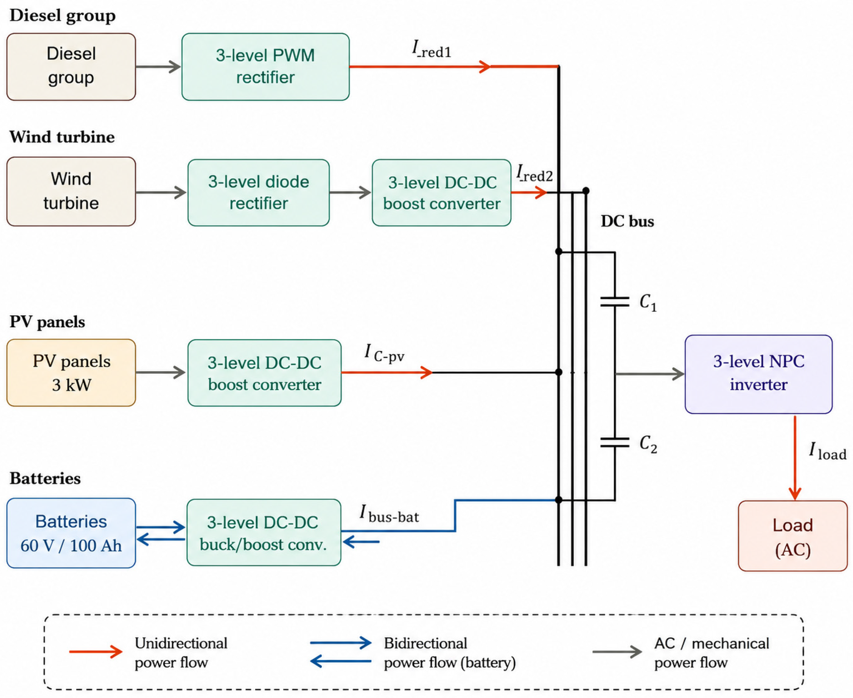
The hybrid system suggested in this work (Figure 1) combines wind and PV energy sources with lithium-ion battery storage and a VSDG to power a separate variable load. The VSDG, unlike traditional fixed-speed units, is used to eliminate excessive emissions, loud noise, and fuel inefficiency when the load is low. Its main control function is to ensure better frequency and voltage performance during transient phases while maintaining DC-bus voltage stability. The use of three-level converters rather than traditional two-level designs is one of the work’s main contributions. To improve power quality, the load current’s Total Harmonic Distortion (THD) is significantly reduced. Furthermore, the control strategy is refined through more precise voltage adjustments and real-time dynamic interaction mastery. The goal of the control strategy is to maximize the penetration of renewable energy sources and to use the battery pack to mitigate the long-term fluctuations associated with solar and wind power. The system minimizes the diesel engine’s operating hours and fuel consumption while guaranteeing dependable energy transfer to the load by coordinating these sources.
While complete theoretical architecture features an isolated AC-side distribution link interface, the physical experimental prototype validated in this stage prioritizes real-time DC-bus voltage stabilization and dynamic power-sharing loops. Accordingly, a programmable DC electronic load is utilized to emulate the exact instantaneous active power demand profile (Pload(t)) of a remote residential cluster. The corresponding AC-side power delivery is governed by a three-level NPC inverter stage utilizing Space Vector PWM. The steady-state power quality indices of this inverter stage (such as terminal voltage regulation, 50 Hz frequency tracking, and strict THD minimization) build directly upon the validated, high-fidelity algorithmic frameworks established in our previous foundational research [20], which serves as the operational baseline for the hardware-level energy management layers presented herein.

3. Proposed Power Control and Ems

This section will present the MPPT control for both PV and wind as follows:

3.1. Incremental Conductance MPPT for PV Arrays

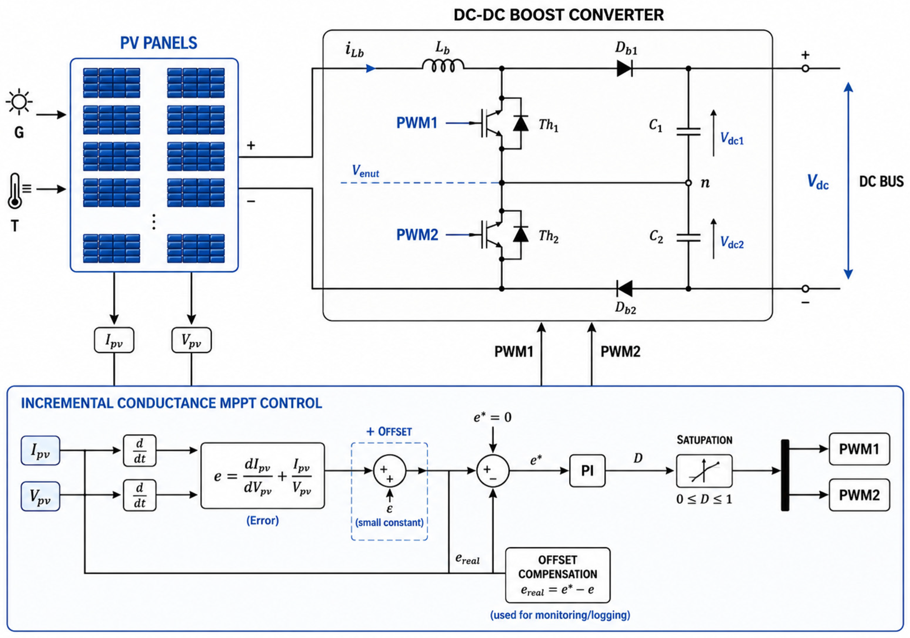
The PV subsystem employs a three-level DC-DC boost converter topology, selected for its ability to achieve high voltage gain while maintaining superior conversion efficiency. This topology offers several distinct technical advantages, including current ripple cancellation and reduced device voltage stress. The interleaved operation of the switching devices inherently cancels input current ripple, significantly reducing electromagnetic interference (EMI) and minimizing the need for bulky input filtering components, thereby enhancing power density. Additionally, each switching device is subjected to only half the output DC bus voltage (Vdc/2), a direct consequence of the series capacitor voltage division inherent to the three-level architecture [19]. This reduced voltage stress allows for the utilization of lower-voltage-rated MOSFETs or IGBTs, which typically exhibit lower switching losses, faster switching transitions, and lower on-state resistance, ultimately improving overall system reliability and reducing cost [21].
For MPPT, the system implements the Incremental Conductance (INC) algorithm as shown in Figure 2. This approach exploits the fundamental characteristic of the PV array’s power-voltage (P-V) curve, where the slope (dP/dV) is zero at the maximum power point (MPP). The algorithm determines the operating point by comparing the incremental conductance (dIPV/dVPV) to the instantaneous conductance (IPV/VPV). This control strategy is discussed in detail in Section 4 [22].
The choice of the incremental conductance (INC) algorithm for implementing MPPT is justified by several major advantages. First, it relies on a rigorous mathematical derivation directly from the current-voltage (I-V) characteristic of the PV panel, thus providing it with a solid theoretical foundation. Second, it allows precise tracking of the maximum power point (MPP) without steady-state oscillation, unlike the classic perturb-and-observe (P&O) algorithm, which continuously generates fluctuations around the MPP and fails to distinguish its own perturbations from actual MPP variations induced by changes in sunlight.
The INC algorithm performs an analytical comparison at each sampling step between the instantaneous conductance (I/V) and the incremental conductance (ΔI/ΔV), enabling it to determine the direction of voltage adjustment deterministically. As soon as the MPP is reached, the perturbation stops, thereby eliminating any steady-state power loss.
Furthermore, in our configuration, this algorithm is deployed on three parallel, three-level DC-DC converters. For each converter, the INC generates a smooth, stable duty-cycle reference, significantly reducing harmonic stress on the power switches and improving the overall quality of the converted power.
Finally, its simple algorithmic structure and low computational cost make it perfectly suited for real-time digital implementation on the dSPACE DS1104 platform. All these properties make the INC the most relevant MPPT strategy for the envisioned island microgrid system, which is subject to highly variable irradiance conditions.

3.2. Variable-Speed Control for Wind Turbines

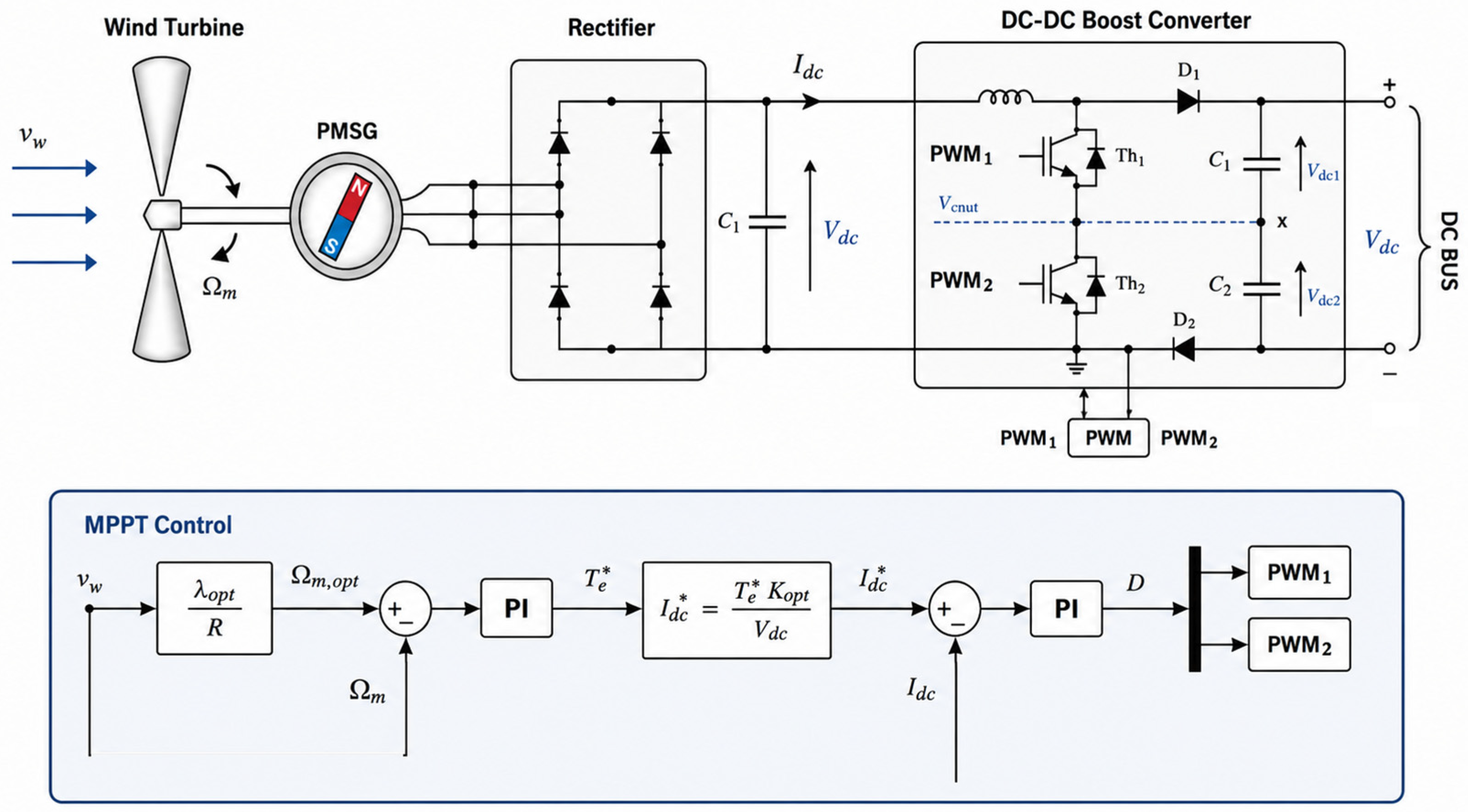
The effectiveness of the control strategy is fundamentally dependent on the hardware architecture. Specifically, the use of a Permanent Magnet Generator (PMG) interfaced through a three-level diode rectifier and a three-level boost converter creates a decoupled interface between the wind turbine and the common DC bus. This hardware arrangement is critical because it allows the converter to independently control the generator speed ( Ω m 1 ) by regulating the current drawn from the generator, regardless of the DC bus voltage or grid conditions [23].
Without this architecture, particularly the boost converter acting as an electronic load, the turbine speed would be dictated by the load, making it impossible to track the optimal tip-speed ratio actively. Thus, the hardware provides the necessary actuation mechanism to enable the control loops to execute their strategies.
The control strategy itself is derived from the mathematical relationship governing wind power to optimize energy extraction [24]. The mechanical power (Pt) captured by the turbine is given by:
P t = 1 2 C p λ , β × ρ × S × V 3
In this equation, the power coefficient CP (λ, β) controls the turbine’s efficiency. For a fixed pitch angle (β), CP is solely a function of the tip-speed ratio (λ), defined as:
λ = Ω m 1 × R t V
The relationship reveals that for any given wind speed V, there exists a unique optimal rotational speed Ω m 1 that maintains λ as the ideal tip-speed ratio (λopt), thereby maximizing CP and, consequently, Pt.
The control strategy, shown in Figure 3, consists of two PI controllers arranged in a cascade structure. The outer loop regulates the turbine speed and outputs the reference current (Idc), while the inner current loop controls the Pulse Width Modulation (PWM) generator to track this reference [25]. This arrangement guarantees maximum power extraction by maintaining the generator at the optimal operating point on the CP curve under varying wind conditions.

4. Control of Three-Level Converters and Energy Storage

Based on the simulation part of this work, the PWM scheme for three-level converters has been described to illustrate load voltage control. Subsequently, the extraction method will be used as a voltage balancing strategy, as outlined below.

4.1. Load Voltage Control Strategy for Isolated Area

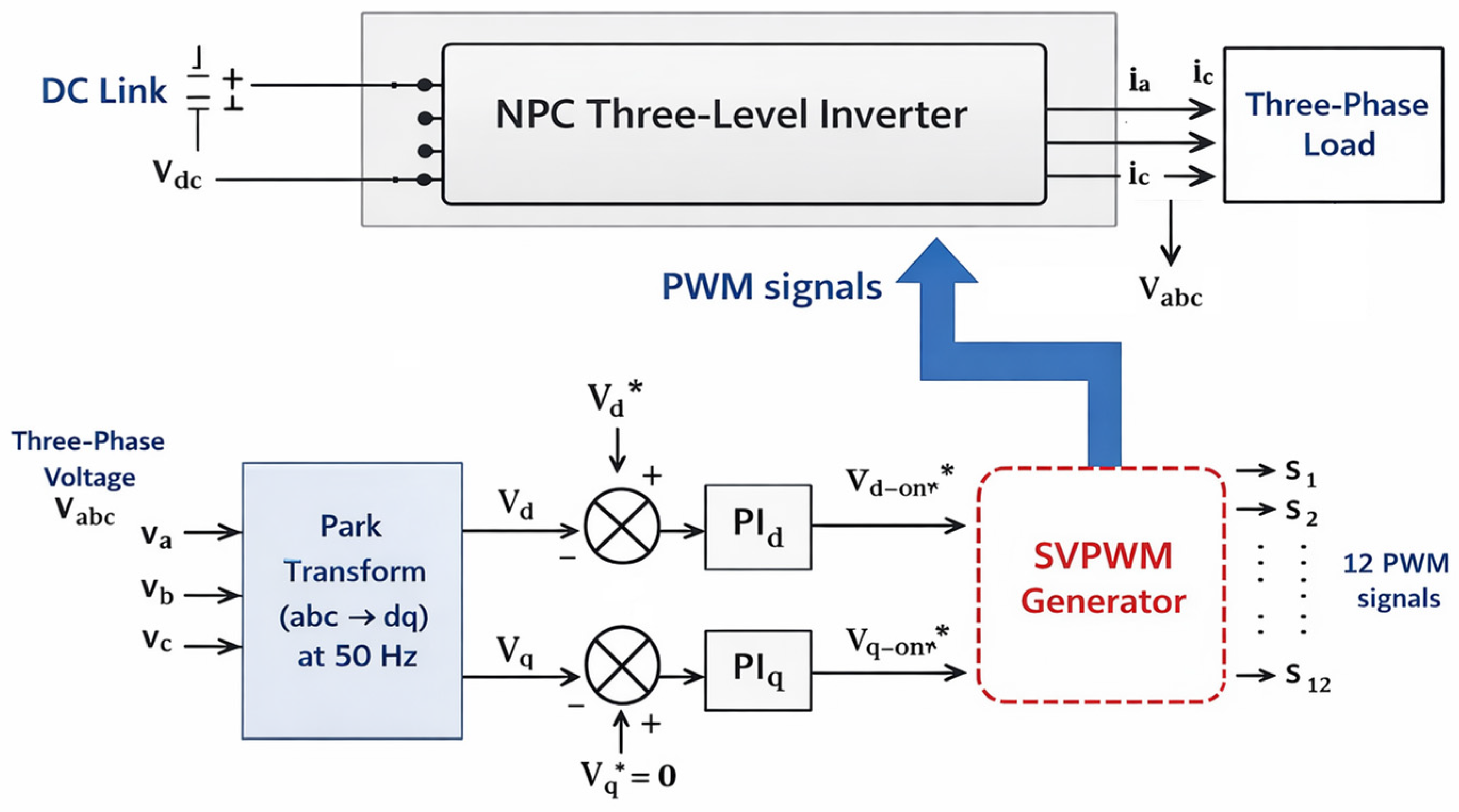
The load voltage control strategy is developed for isolated microgrid applications, where the energy is supplied to the load through a three-level neutral-point-clamped (NPC) inverter [10], as illustrated in Figure 4. The DC-link voltage V d c feeds the NPC inverter, which generates three-phase voltages v a v b v c applied to the load. To ensure stable operation in islanded mode, the control system must maintain a constant voltage despite fluctuations in load [26].
In order to achieve effective voltage regulation, the control is performed in the synchronous reference frame using the park transformation (abc–dq) at 50 Hz. The measured three-phase voltages V a b c are transformed into direct and quadrature components V d V q , enabling decoupled and linear control of the system.
The RMS voltage control is implemented by regulating the d -axis component V d to its reference V d * , while the q -axis component is controlled to zero V q * 0 , ensuring proper voltage orientation and stability [27]. The resulting errors are processed through proportional integral (PI) controllers to generate the reference voltages V d * V q * .
Given the three-level architecture of the NPC, the SVPWM block generates 12 distinct PWM signals ( S 1 , S 2 , , S 12 ) to drive the semiconductor switches, effectively synthesizing the required output voltage to satisfy the load demand. The SVPWM technique ensures optimal utilization of the DC bus voltage and reduced harmonic distortion. This method is preferred for three-level topologies due to its superior harmonic performance and efficient utilization of the DC link voltage [28,29,30,31,32]. This scheme was implemented in our previous simulation [20], which included all parameters related to AC load, THD, DC-link, etc.
The control layout for the three-level NPC inverter stage, illustrated schematically in Figure 4, employs SVPWM to achieve optimal utilization of the DC-link voltage and superior harmonic performance. The quantitative efficacy of this specific dual-loop voltage and current regulation scheme was rigorously verified under severe operating conditions in [20]. The benchmarking results demonstrated that the synchronous dq-frame voltage components (Vd and Vq) track their references with an empirical transient overshoot of less than 5% and minimal steady-state error, while providing inherent, highly significant suppression of the total line-current THD. This validated harmonic performance ensures that when the DC-link voltage is tightly stabilized by the physical hardware EMS, the synchronized 3L-NPC inverter structurally delivers high-quality, grid-compliant AC energy.

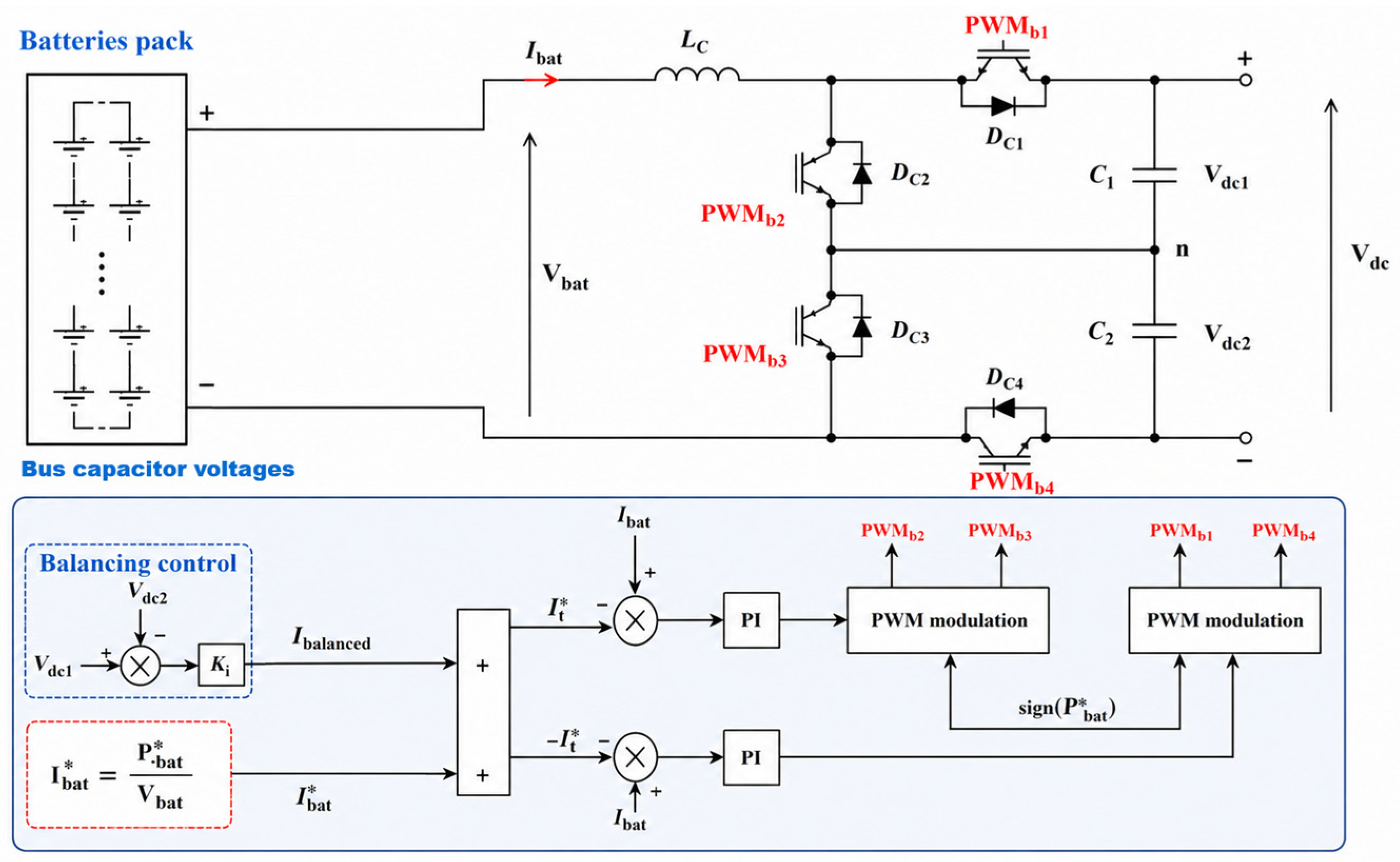
4.2. Batteries Current Control and DC-Bus Capacitors Voltage Balancing

The BESS is interfaced with the DC bus through a three-level bidirectional DC/DC converter, as illustrated in Figure 5. This topology, modeled based on the parameters in [33], is utilized to halve the voltage stress on the semiconductor devices and significantly reduce the current ripple through the coupling inductor (LC).
The control architecture, detailed in the lower portion of this figure, is designed to achieve power tracking while ensuring neutral-point voltage stability. The total battery current reference (It) is synthesized by combining the fundamental current command with a balancing component:
Fundamental Current Reference (Ibat*): derived from the supervisory power dispatch command (Pbat*) and the instantaneous battery voltage (Vbat*), ensuring that the BESS follows the required mission profile.
Balancing Control (Pbalance): to prevent neutral-point drift between the split-bus capacitors (C1, C2), a proportional–integral (PI) regulator processes the differential voltage (Pdc1 − Pdc2). The resulting compensation current (Ibalance) is added/subtracted from the primary reference to maintain voltage equilibrium across the DC bus.
The current error is regulated by dual PI controllers that generate the modulation signals for the PWM stages. To minimize high-frequency EMI and further reduce battery current stress, the PWM signals are interleaved with a 180° phase shift between the switch pairs (PWMb2, PWMb3, and PWMb1, PWMb4, consistent with the modulation strategies in [34,35].
The operational mode of the converter is governed by the polarity of the power reference (Pbat*):
  • Boost Mode (Pbat* > 0): The system operates as a step-up converter to discharge the batteries and support the DC bus.
  • Buck Mode (Pbat* ≤ 0): The system operates as a step-down converter to charge the battery bank from the surplus energy in the microgrid.

4.3. Power Reference Extraction for Batteries and Diesel Generator

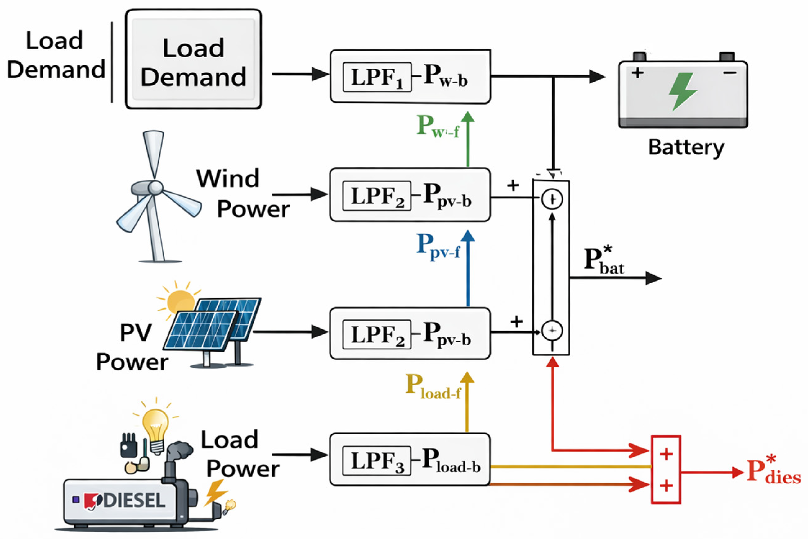
In proposed hybrid renewable energy systems, disturbances interact at the point of common coupling due to the inherent variability of renewable sources and load demand. To mitigate these interactions, the proposed control strategy exploits the frequency-domain characteristics of power fluctuations [36]. By regulating the DC-bus voltage to a constant value, disturbances are effectively transferred to the current signals [37]. Based on that, the goal is to extract the power references for the battery ( P b a t * ) and the diesel generator ( P d i e s * ) by filtering the net power of the hybrid system.
The logic follows a power balance equation where the difference between renewable generation ( P W + P P V ) and the load demand ( P l o a d ) is processed through Low-Pass Filters (LPF) to separate high-frequency fluctuations (handled by batteries) from long-term trends (handled by the diesel generator).
To ensure clarity regarding the system-wide power flow equations, all power sign conventions are defined relative to the shared common DC-bus node. Photovoltaic power ( P P V ) and wind power ( P W ) are defined strictly as positive quantities injected into the bus. In contrast, the total consumer demand ( P l o a d ) is a positive quantity drawn from the bus.
The variable-speed diesel generator power ( P d i e s ) operates as a unidirectional positive source providing low-frequency baseline support. Conversely, the battery storage power ( P b a t * ) is bidirectional; a positive sign (+ P b a t * ) denotes a discharging state (boost operation) supporting the DC link, whereas a negative sign (− P b a t * ) denotes a charging state (buck operation) to absorb excess generation. This unified sign convention strictly governs the reference generation loops and aligns with the empirical polarities observed in the experimental waveforms.
The diagram for this system typically consists of the following mathematical and logical stages:
  • Power Summation: The net power ( P n e t ) is calculated by subtracting the load demand from the total renewable production:
  • P n e t = ( P W + P P V ) − P l o a d
  • Low-Pass Filtering (LPF): The cutoff frequency is chosen based on the desired response time of the diesel engine.
  • The Diesel Reference ( P d i e s * ) is obtained by passing the net power through an LPF. This ensures the diesel generator only responds to slow, steady-state changes in demand or production.
  • Battery Reference Extraction: The battery Reference ( P b a t * ) is the difference between the unfiltered net power and the filtered diesel reference. This represents the high-frequency “ripple” or transient disturbances:
  • P b a t * = P n e t P d i e s *
In the extraction-based method, the battery power reference is used for current control, while the DC voltage across the capacitor balances the voltage control. This results in a cascaded dual-loop control strategy comprising a voltage-balancing loop and a current control loop. Such architecture enables the simultaneous regulation of battery power and the balancing of the DC-link capacitor voltages.
The used battery model is given in [33]. The control method of the three-level buck/boost converter is based on the battery’s current management as presented in Figure 5, where the current reference I b a t * is calculated from the batteries reference power P b a t * , given in Figure 6, and the DC-bus capacitors’ voltage balancing control, to avoid their destruction.
The reference battery current (Figure 5) is obtained from the desired battery power as
I b a t * = P b a t * V b a t
To ensure equal voltage distribution across the split DC-link capacitors, a balancing current is introduced based on the voltage difference between the two capacitors:
I b a l a n c e d = K i V d c 2 V d c 1
The total current reference I t * is then defined as combining the power control objective with a voltage balancing term
I t * = I b a t * + I b a l a n c e d
This formulation enables the controller to regulate power flow while compensating for any imbalance in the DC-link voltages.
The bidirectional operation of the converter depends on the sign of the reference power P b a t * . Specifically, if P b a t * > 0 , the converter operates in boost mode, and the batteries discharge. Conversely, if P b a t * 0 , the converter operates in buck mode, resulting in battery charging.
The current control loop is responsible for accurate tracking of the reference current I t * . It employs proportional–integral (PI) controllers to minimize the error between the measured battery current I b a t and its reference. The control signals generated by the PI controllers are used as inputs to the PWM modulation stage.
To enable bidirectional power flow, a sign function based on the reference power is incorporated:
s = s i g n ( P b a t * )
To properly drive the converter switches, the generated PWM signals follow a phase-shifted pattern. The control signals are phase-shifted by 180 between P W M b 2 and P W M b 3 , and similarly between P W M b 1 and P W M b 4 , as reported in [34,38,39,40]. This phase-shifting ensures proper complementary switching and reduces switching stress, thereby improving converter performance.
The proposed cascaded control structure effectively decouples the slow voltage-balancing dynamics from the fast current regulation loop, thereby enhancing system stability, improving dynamic response, and ensuring reliable operation under varying load and power conditions.

5. Variable Speed Diesel Generator Control Using Three-Level

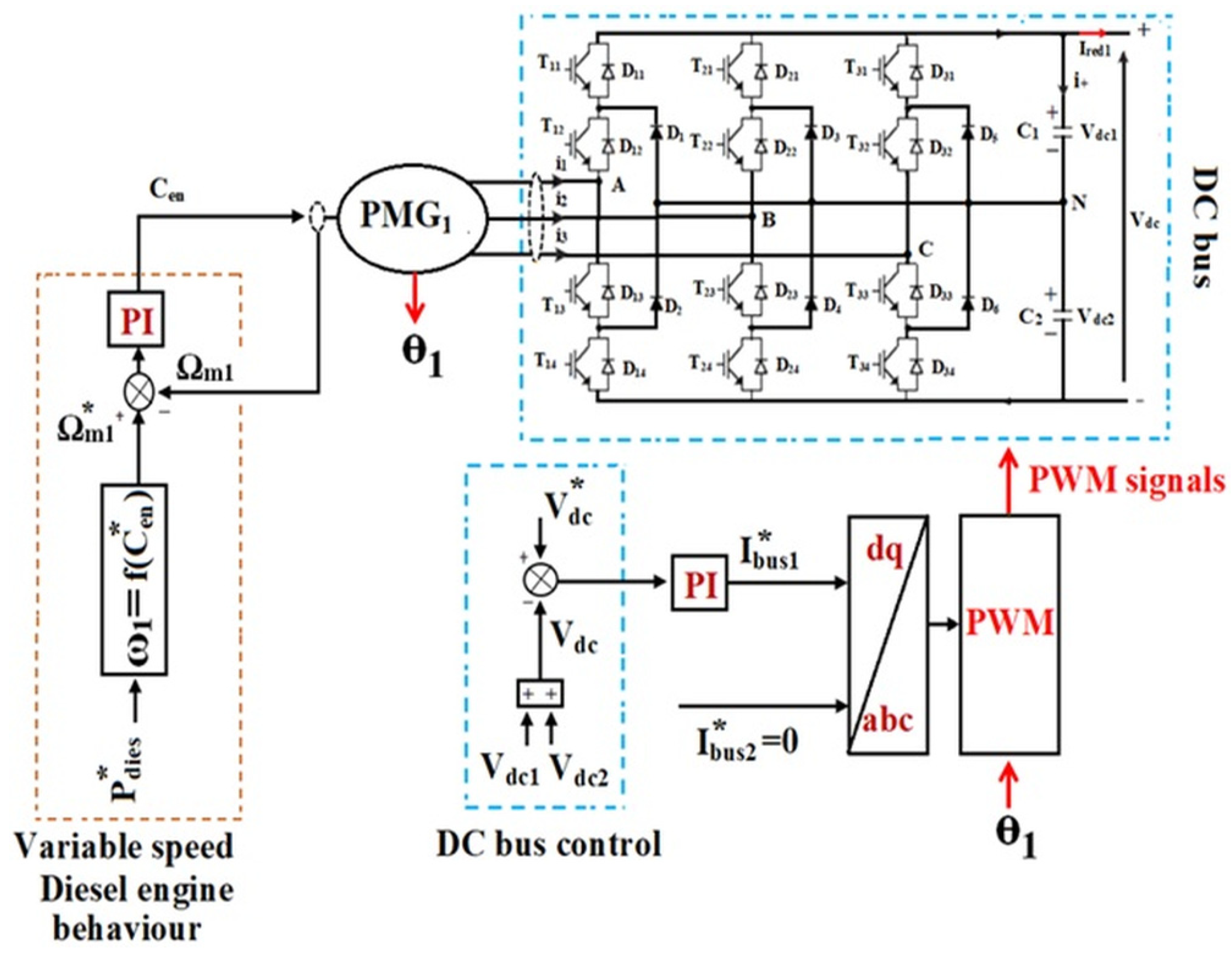
The VSDG serves as the primary stable energy source in the microgrid and regulates the DC-bus voltage. As illustrated in Figure 7, the overall DG control architecture comprises two cascaded loops: an outer DC-bus voltage control loop and an inner PMG1 speed control loop.
The DC-Bus Voltage Control regulates the DC-bus voltage by comparing the measured DC-bus voltage V d c against a reference value V d c * . The voltage error is processed by a proportional–integral (PI) controller, which generates the d-axis bus current reference I b u s 1 * . The q-axis reference is set to zero ( I b u s 2 * = 0 ) to ensure unity power factor operation. These current references are then transformed from the dq reference frame to the abc frame using the rotor position ( θ 1 ), and the resulting signals are fed to a PWM stage to generate the switching signals for the three-phase converter bridge.
The PMG speed control governs the mechanical behavior of the diesel engine generator set. The control input C e n is derived from the energy management layer and feeds into the speed control chain. A polynomial fuel-flow function, ω 1 = f ( C e n ) models the variable-speed diesel engine behavior and yields the speed reference Ω m 1 * . The measured generator speed Ω m 1 is compared with this reference, and a PI controller regulates the speed error. The PI output constitutes the mechanical torque command transmitted to PMG, thereby closing the speed control loop.
The three-phase diode-bridge rectifier connected to PMG supplies the DC bus with capacitors C 1 and C 2 providing the split DC-bus voltages V d c 1 and V d c 2 . The diesel generator rated power P d i e s * is used as a supervisory feedforward signal to schedule the operating point of the speed reference generation function.

6. Experimental Verification of Power Control Strategies

The description of the experimental test bench and conditions will be as follows:

6.1. Experimental Validation of the Control Strategy

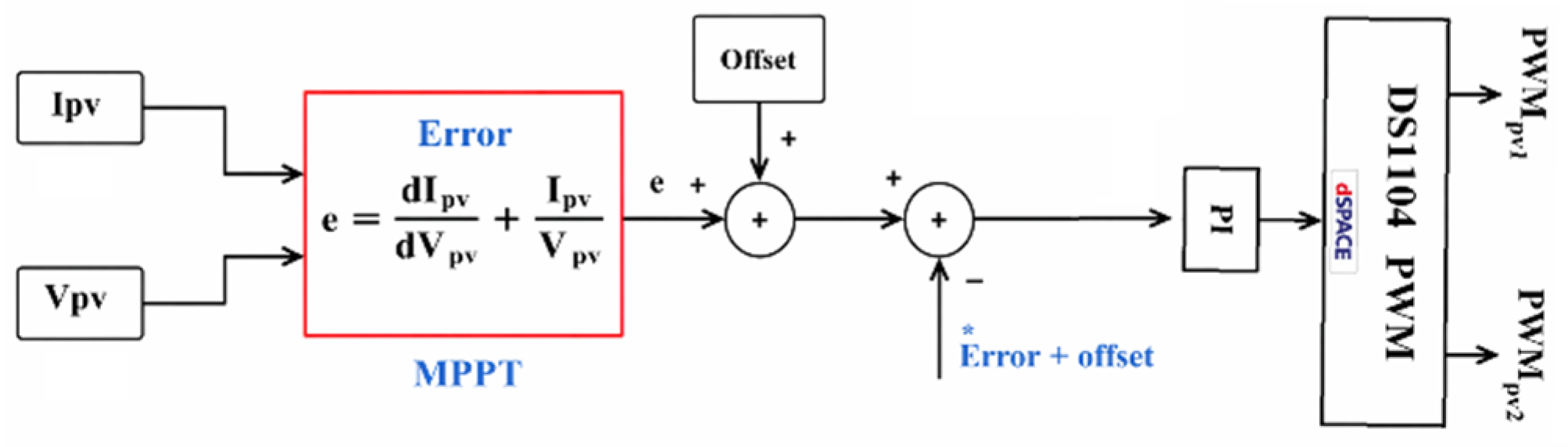
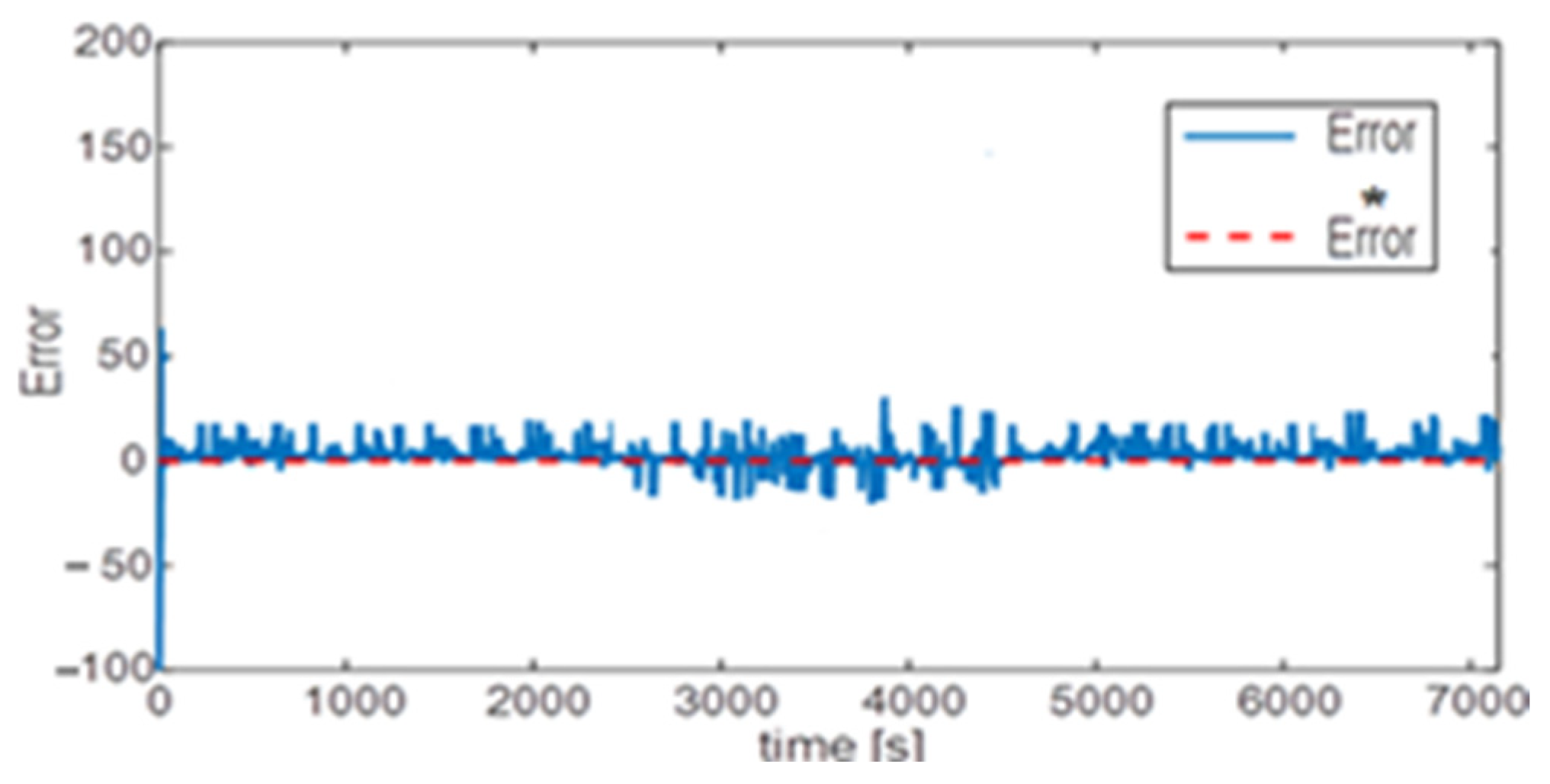
The extraction of the maximum power from panels is based on the incremental conductance MPPT control developed in Section 3.1. A constant offset is added to the control loop, as illustrated in Figure 8, because it is very difficult to drive the error to zero experimentally due to the current/voltage sensors’ sensitivity and the residual errors in the measurement chains. In real-time operations, the offset is subtracted from the system response to obtain the real error.
The Incremental Conductance (INC) algorithm is used to achieve the MPPT as shown in Figure 8. To determine the Maximum Power Point (MPP), the controller compares the incremental conductance (dIpv/dVpv) with the instantaneous conductance (Ipv/Vpv). The following equilibrium condition defines the error (e):I
e = I p v V p v + d I p v d V p v 0
This error is processed by a PI regulator, which drives it toward zero and modifies the converter’s duty cycle (D). Phase-shifted PWM carriers (Vtri1, Vtri2) are used to generate the final control signal, which guarantees a stable DC-link voltage and balanced operation of the three-level architecture.

6.2. Battery Storage Management Based on State of Charge (SoC) Limits

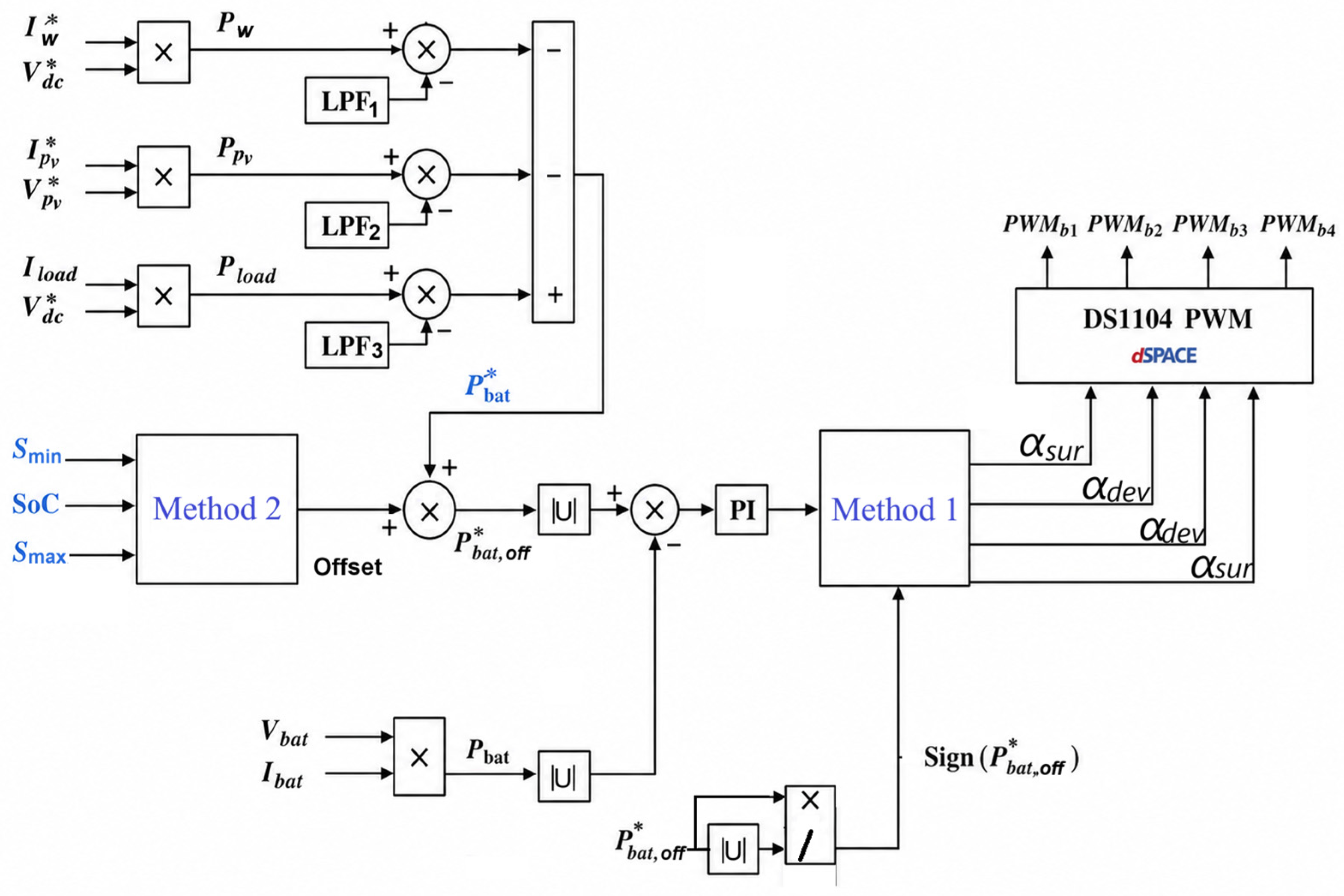
The battery power control strategy incorporating SoC constraints is illustrated in Figure 9. This control approach ensures safe and efficient operation of the battery system within a microgrid by dynamically adapting the battery power reference according to the SoC limits.
The control structure is based on modifying the reference battery power obtained from the mission profile extraction method described in Section 4.3. To achieve this, an additional supervisory layer, referred to as Method 2, is integrated into the converter’s control loop and interfaces with the batteries.
Method 1 determines the operating mode of the bidirectional converter based on the sign of the corrected power reference P b a t - o f f * . Specifically:
  • If s i g n   ( P b a t - o f f * ) 0 , the converter operates in buck mode, during which energy is transferred from the DC bus to the battery bank for charging.
  • If s i g n ( P b a t - o f f * ) > 0 , the converter operates in boost mode, during which the battery bank supplies power to the DC bus to support load demand.
This decision is based on the sign of the adjusted power reference. When the reference power is negative or zero, the converter operates in buck mode, allowing the batteries to absorb energy and charge. In contrast, when the reference power is positive, the converter operates in boost mode, enabling the batteries to supply energy to the DC bus.
Method 2 monitors the battery SoC in real time and applies a corrective power offset to the battery power reference P b a t * , which is obtained from the battery mission profile extraction method described in Section 5. The offset logic operates according to the following three conditions:
  • If S o C < S m i n , a corrective offset of 1 kW is added to P b a t * to limit further discharge and prevent the SoC from falling below the minimum threshold.
  • If S m i n S o C S m a x , no offset is applied and the battery follows the reference P b a t * without restriction.
  • If S o C > S m a x , a corrective offset of + 1 kW is added to P b a t * to limit further charging and prevent the SoC from exceeding the maximum threshold.
The modified power reference, denoted P b a t - o f f * , is the sum of P b a t * and the SoC dependent offset, and it serves as the input to the subsequent converter control stage. The SoC is estimated by integrating the measured battery current I b a t over time, where the initial SoC value S o C 0 is set to 88% and Q denotes the rated battery capacity in ampere-seconds.
The resulting control signals are subsequently used to drive the PWM generation stage, ensuring proper switching of the converter and accurate tracking of the desired power flow.
Overall, the proposed control strategy enhances battery lifetime and system reliability by preventing overcharge and deep discharge conditions, while maintaining effective power management within the microgrid.

7. Experimental Platform and Real-Time Implementation

A comprehensive description of the principal hardware components and experimental infrastructure used in this study is presented in the subsequent sections to provide a clear understanding of the research objectives and the proposed control methodology.

7.1. Hardware-in-the-Loop (HIL) and Prototyping

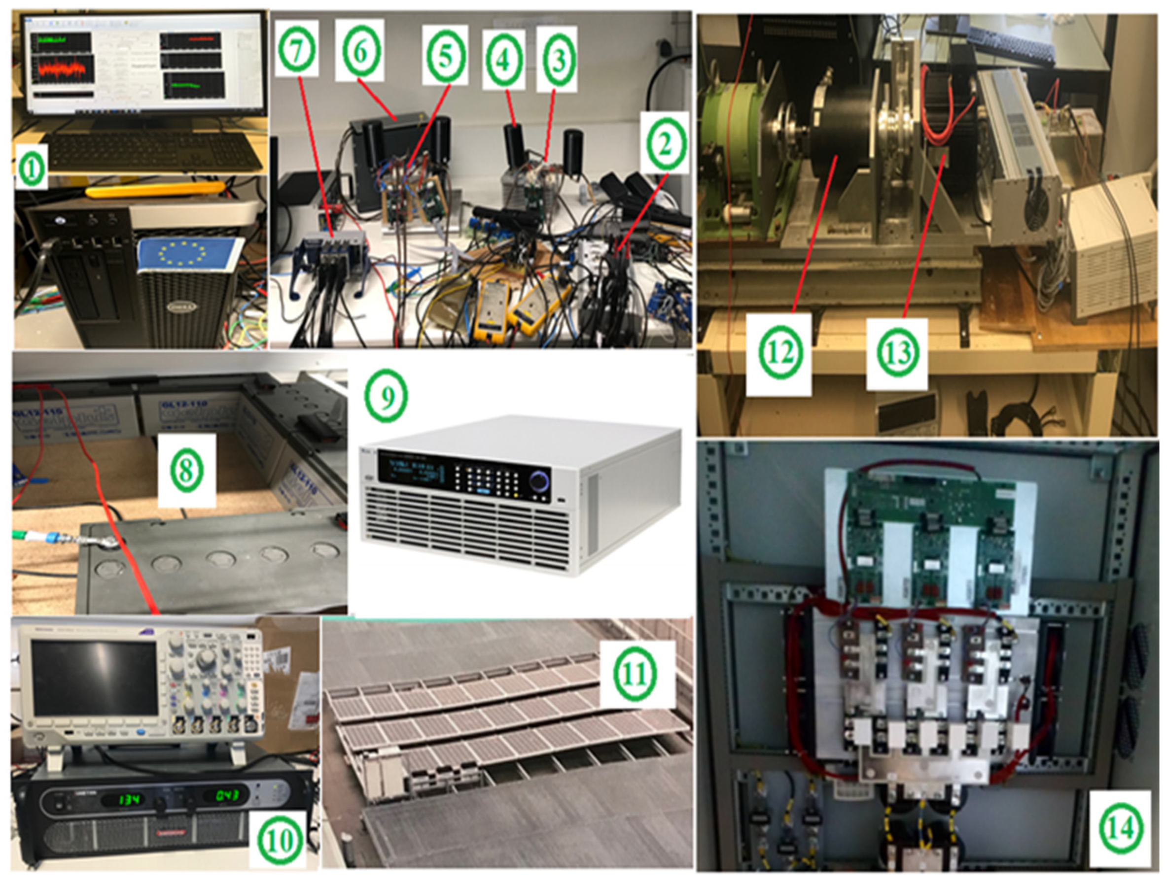
An experimental test bench, scaled to 1:22, was developed to validate the proposed control strategies. The setup, shown in Figure 10, consists of PV panels with a maximum power of 3 kW, a battery pack rated at 60 V/100 Ah, and a laboratory-developed wind turbine emulator based on a PMG with a rated torque of 26 N·m and a rated speed of 420 rpm. Furthermore, a controlled DC source is used to emulate the behavior of a diesel generator. At the same time, a programmable DC electronic load is connected to the DC bus to replicate the energy demand of an islanded microgrid.

7.2. Power Electronics Control System and Real-Time Controller

The main components of the control system comprise three-level converter prototypes and a three-level rectifier, with real-time control implemented on a dSPACE DS1104 platform. All stages of the system architecture employ three-level converter topologies: DC–DC converters interface the batteries and PV system with the DC bus, whereas the VSDG and the wind turbine are connected through three-level rectifiers.
The power management strategies are implemented on the DS1104 controller. The parameters used in the control loops are summarized in Table 1.

7.3. Experimental Test Results and Discussion

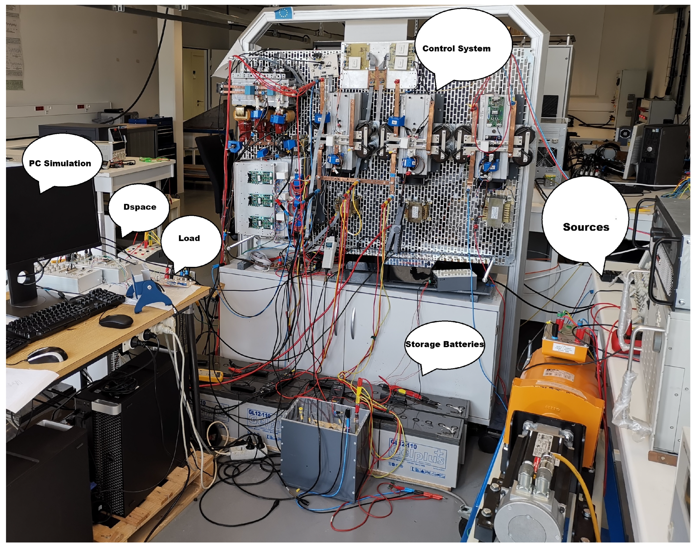
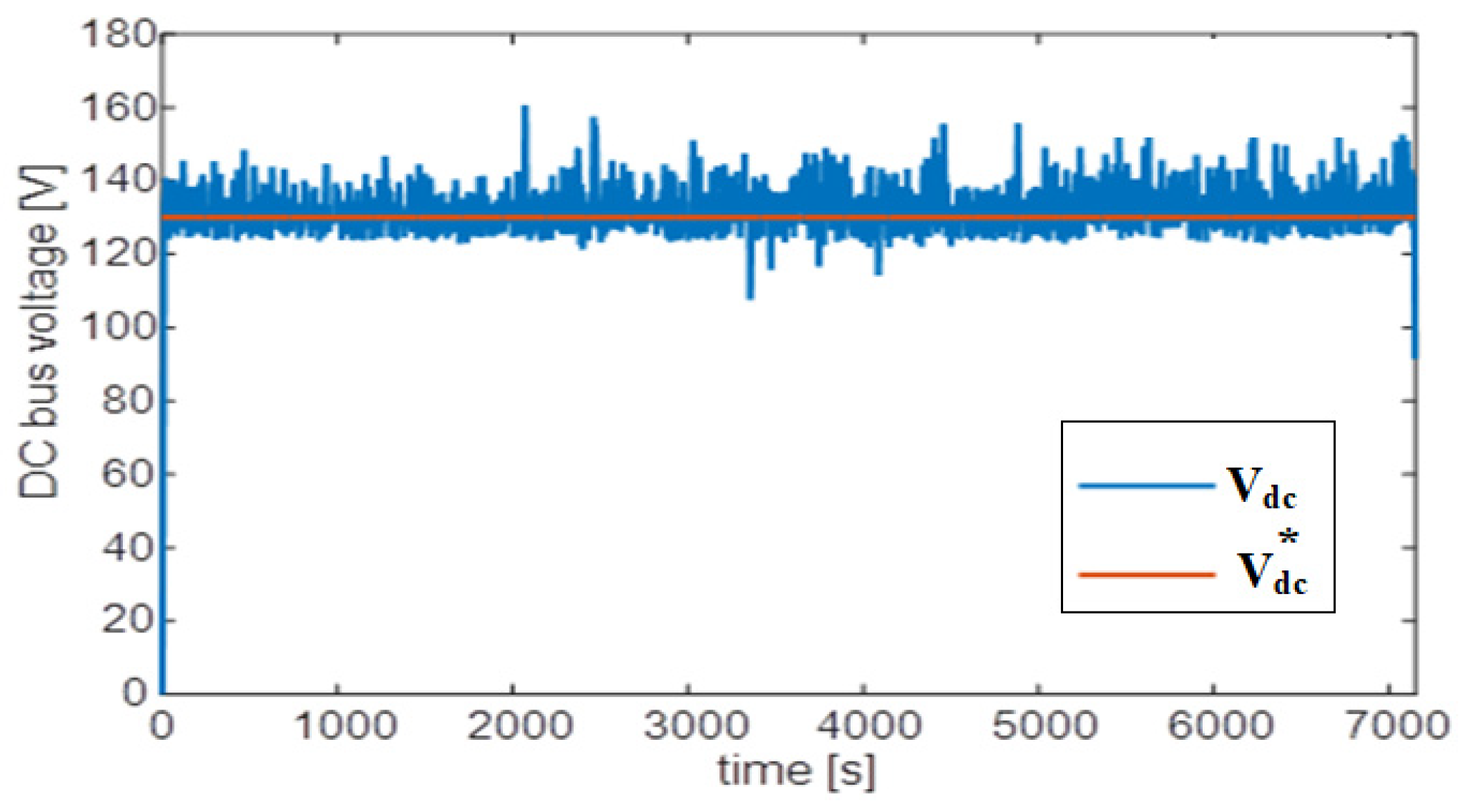
For experimental validation, the DC-bus voltage is regulated at 130 V due to the limited number of batteries available in the laboratory (Figure 11). This voltage has been generated by a controlled DC source used to emulate a diesel generator.
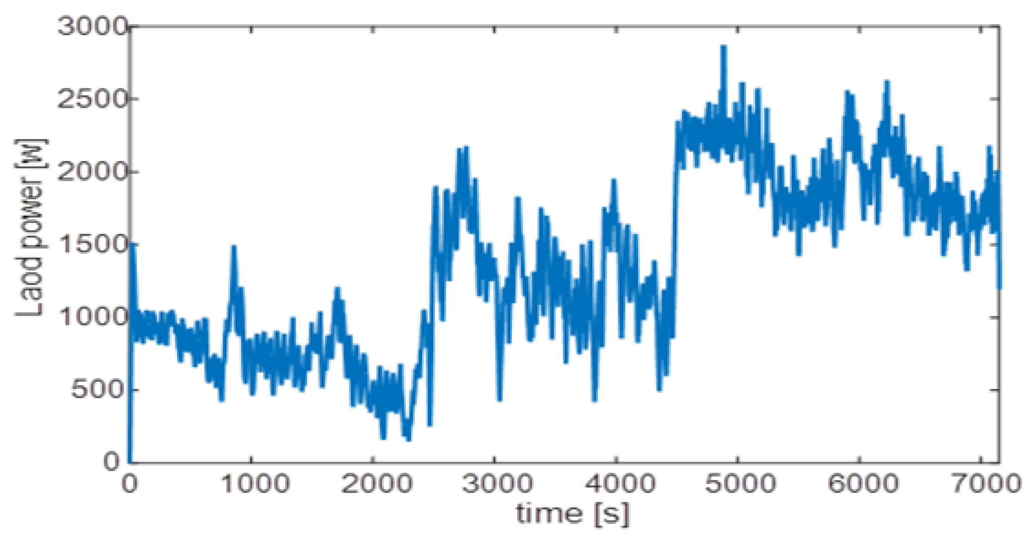
The measured active power at the NPC inverter input, representing the aggregate energy consumption of domestic appliances in the islanded area, is presented in Figure 12. The profile spans a two-hour observation window and reflects typical residential demand behavior in an islanded microgrid.
As shown in Figure 12, the load exhibits noticeable variability, with intermittent peaks and fluctuations, typical of residential consumption patterns. The demand remains relatively moderate during the initial period, followed by increased variations and transient peaks due to the stochastic operation of household appliances. A higher and more sustained power level is observed in the later stage, corresponding to peak usage conditions.
This variable and unpredictable load profile highlights the need for an effective energy management strategy to maintain DC-bus voltage stability and ensure reliable power delivery within the islanded microgrid under dynamic demand conditions.
The real-time tracking performance of the shared DC-link voltage during the 7150 s mission profile is illustrated in Figure 13. As shown, the measured voltage remains close to the reference value, which is fixed at 130 V. This reference tracking is maintained throughout the entire measurement period, with the measured voltage varying between 130 V and 145 V, representing a maximum peak deviation of 11.5% under stochastic load and generation conditions. In contrast, the reference stays constant at 130 V. The control, implemented via a diesel emulator, maintains a constant DC-bus voltage despite potential variations in load or generation. Under steady-state operation, the control loop maintains excellent regulation, keeping the high-frequency switching ripple within a negligible band of +/−1.5% around the nominal reference ( V d c * = 130 V). During periods of severe stochastic stress, where sudden residential load peaks coincide with abrupt drops in PV and wind generation, the maximum dynamic peak deviation reaches a worst-case value of ∆Vmax = 15 V (Vdc,max approx. 145 V), which corresponds to a maximum transient error of 11.54%.
This localized deviation represents an acceptable transient band for this 1:22 reduced-scale laboratory bench. Because the nominal reference was downscaled to 130 V due to physical limitations of the battery bank, instantaneous power imbalances result in a higher percentage error than in a standard full-scale high-voltage link. Crucially, the control loops demonstrate strong damping, preventing voltage runaway or collapse and rapidly restoring the DC-link potential to its steady-state reference once power balance is reestablished.
The experimental MPPT tracking error of the PV panels is presented in Figure 14. The figure shows the tracking error over time for three different conditions, represented by solid, dashed, and dotted lines. In all cases, the average value of the error is regulated to zero, indicating that the MPPT algorithm successfully maintains the operating point at the maximum power condition. This behavior corresponds to satisfactory conditions for extracting the maximum available power from the PV panels. The incremental conductance algorithm demonstrated high precision, with the average tracking error converging to zero across all tested irradiance profiles.
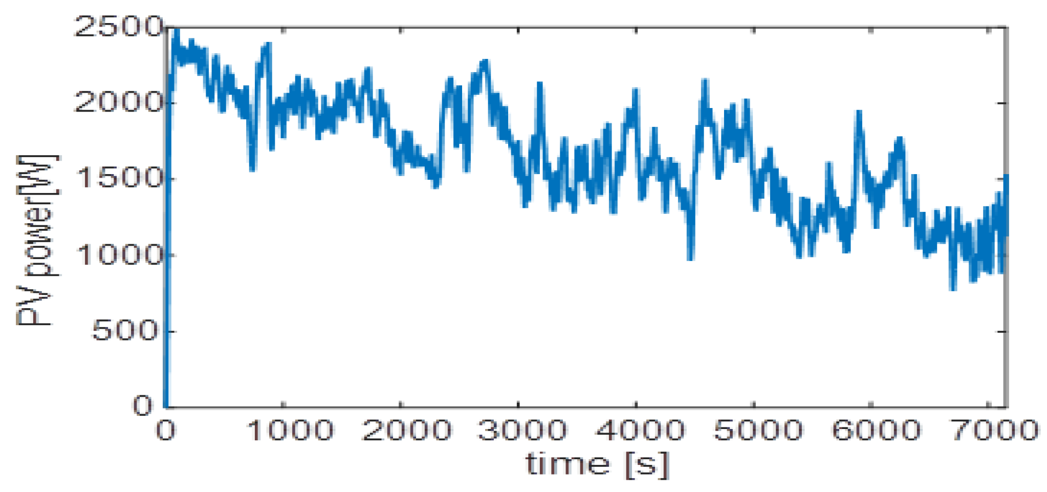
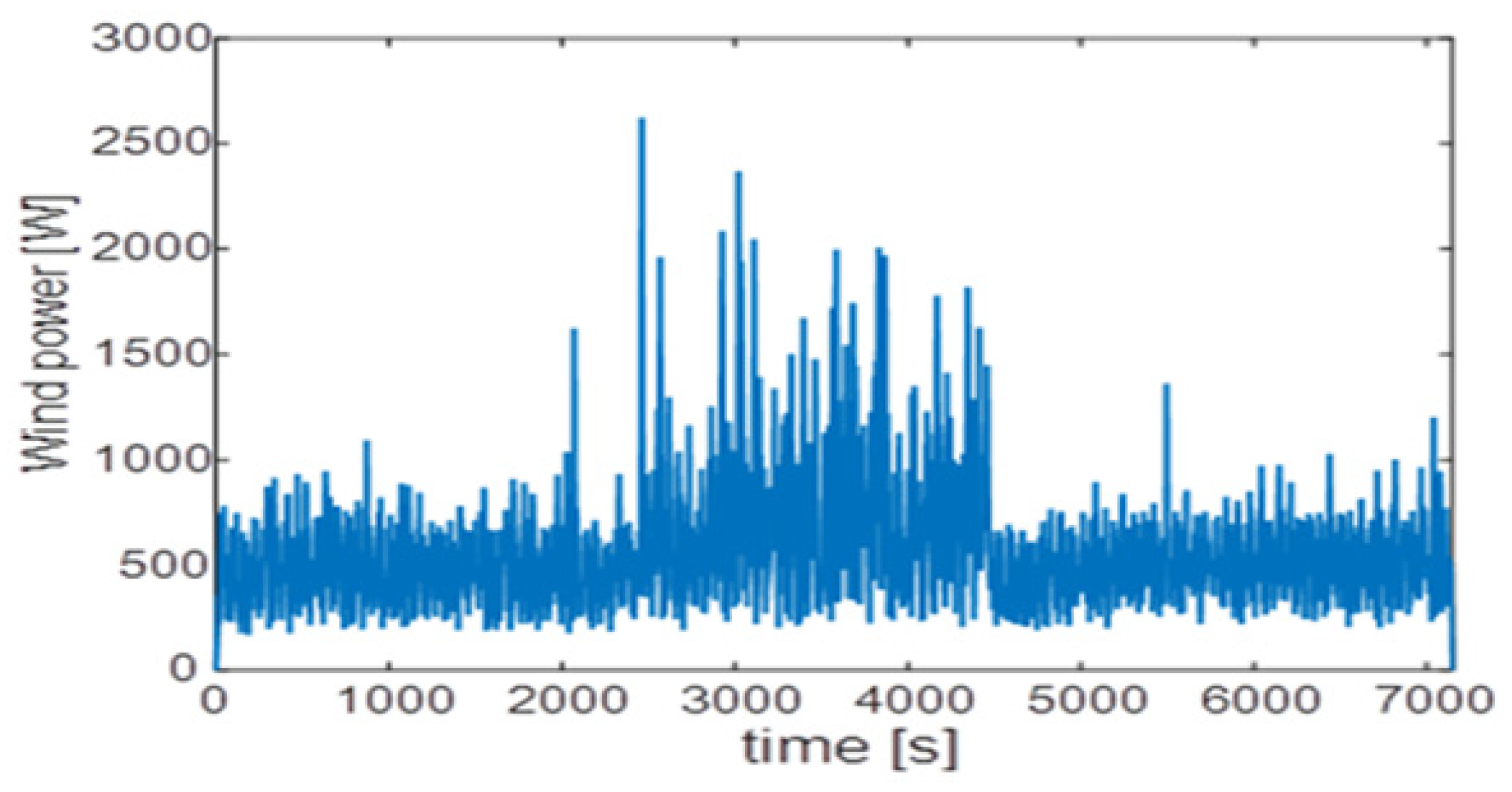
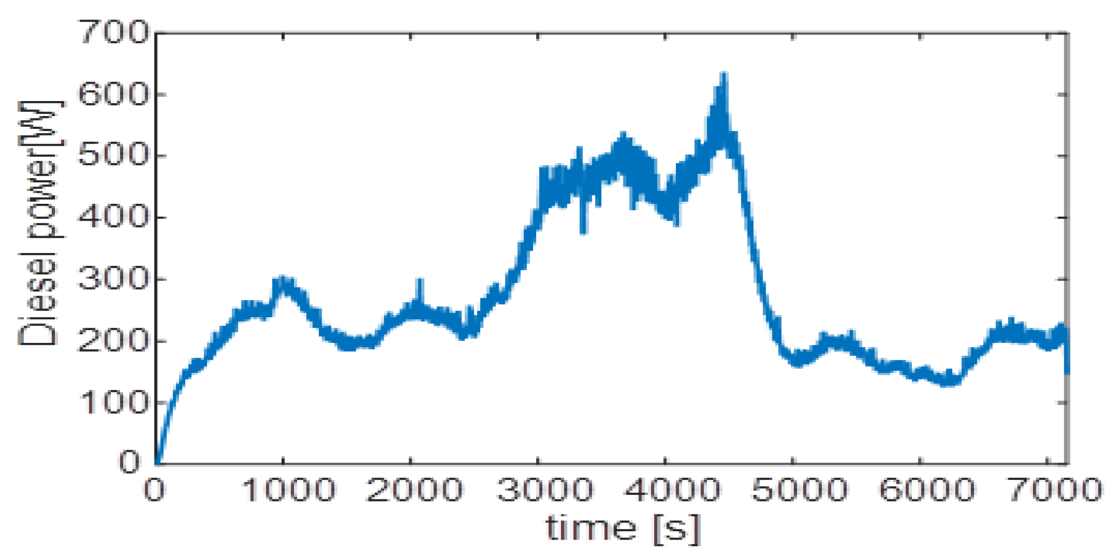
The measured output power of the PV panels and the wind turbine is shown in Figure 15 and Figure 16, respectively. Both profiles exhibit significant time-varying fluctuations attributable to changes in solar irradiance and wind speed over the two-hour measurement period. The PV power decreases progressively from approximately 2400 W to around 1000 W, reflecting a declining irradiance trend, while the wind power oscillates between 200 W and 2600 W with high-frequency intermittency throughout the profile. The diesel generator effectively compensated for low-frequency imbalances, peaking at 630 W and settling at a steady-state level of 200 W.
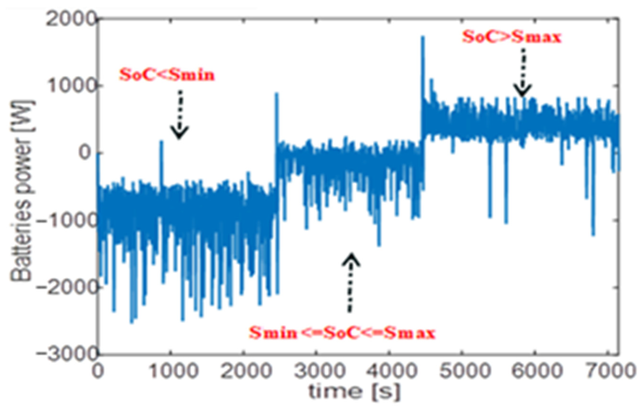
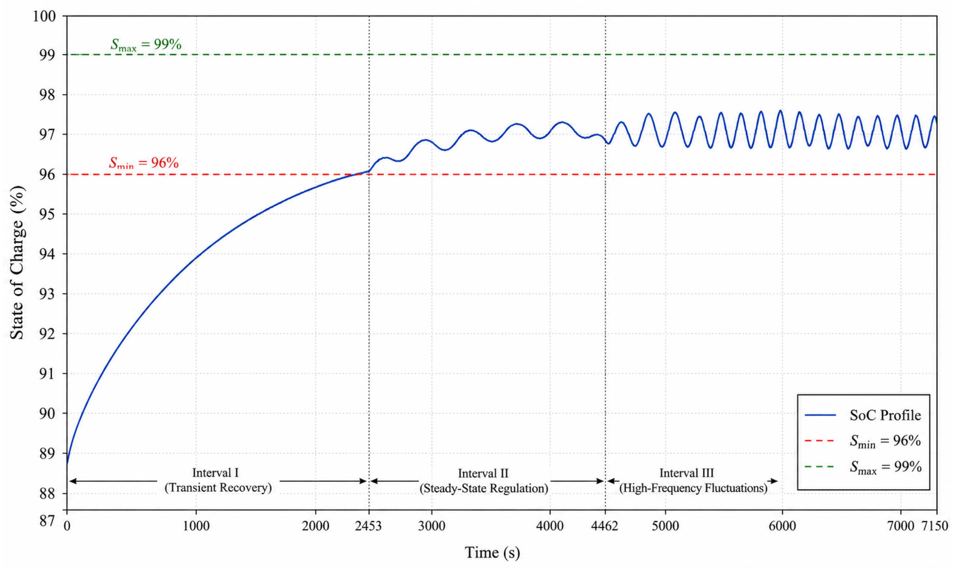
The battery power contribution to microgrid power fluctuation compensation is shown in Figure 17. In contrast, the corresponding temporal trajectory of the battery SoC is explicitly tracked in Figure 18. As observed, the battery bank effectively absorbs and releases power in response to the combined fluctuations of the PV and wind sources, while respecting the SoC boundaries enforced by Method 2. Three distinct operating intervals are identified across the 7150 s mission profile:
  • Interval I ( 0 t 2453 s, S o C < S m i n ): The battery predominantly operates in charging mode, storing surplus energy produced by the renewable sources while simultaneously compensating power fluctuations. As validated by the dynamic tracking in Figure 18, the SoC recovers smoothly from its initial depleted state of 88% up to the minimum nominal operational threshold ( S m i n = 96%).
  • Interval II ( 2453 t 4462 s, S m i n S o C S m a x ): The battery operates in normal mode within the prescribed 3% SoC operating window, performing micro charge–discharge cycles symmetrically around zero net power. Method 2 does not apply a corrective offset, confirming that the battery power reference follows the renewable fluctuation signal directly without SoC boundary intervention. This is visually confirmed in Figure 18, where the SoC exhibits stable, minor oscillations perfectly bound between S m i n   a n d   S m a x .
  • Interval III ( 4462 t 7150 s, S o C > S m a x ): The battery transitions to sustained discharge mode, discharging the previously stored energy to the DC bus while continuing to compensate for residual power fluctuations. Despite these prolonged, stochastic micro-cycles, the SoC profile remains tightly regulated and never breaches the upper degradation limit ( S m a x = 99%).
The explicit synchronization of the power profile in Figure 17 with the SoC trajectory in Figure 18 confirms that the proposed battery control strategy successfully manages dynamic power allocation across all three operational regimes while strictly enforcing physical capacity constraints.
It confirms that the proposed battery control strategy successfully compensates for power fluctuations across all three SoC operating regimes while enforcing the prescribed charge limits throughout the microgrid mission profile.
The measured diesel generator power delivered to the microgrid DC bus is presented in Figure 18. As observed, the DG power profile reflects the low-frequency component of the net power fluctuations, consistent with the slow dynamic response characteristic of diesel engine generator sets. The DG output rises gradually from approximately 150 W, peaks at around 630 W, and settles to a steady-state level of approximately 200 W toward the end of the profile. This behavior confirms that the DG effectively handles the slow power imbalance component within the microgrid, while the battery bank manages the higher-frequency fluctuations.
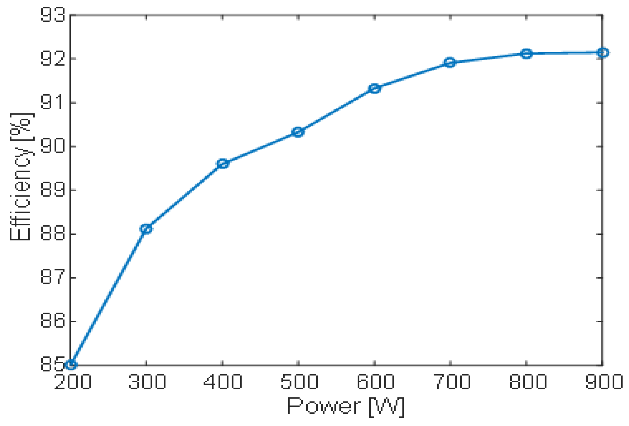
Figure 19 presents the efficiency of the three-level bidirectional DC/DC converter operating in boost mode. The results indicate that efficiency increases with output power and show a robust efficiency range of 85% to 92%, reaching a peak efficiency of 92% at a 900 W rated power point in Figure 20. This demonstrates satisfactory converter performance; however, further improvements can be achieved through electrical design optimization, such as reducing conduction losses and employing low-loss semiconductor devices.
The three-level NPC converter topology adopted throughout the proposed microgrid architecture provides a substantial technical advantage over conventional two-level converters. Under a three-level configuration, the voltage stress across each semiconductor switch is constrained to half of the total DC-link voltage during commutation events. Furthermore, the three-level topology produces an output waveform with lower harmonic content and an effective increase in the dominant harmonic frequencies compared with conventional two-level converters, enabling the use of smaller passive filter components while facilitating compliance with IEEE 519 harmonic distortion limits. Consequently, these reduced voltage steps inherently lower the dv/dt stress on the structural insulation and mitigate system-wide EMI.
In the reduced-scale experimental platform implemented on the dSPACE DS1104 real-time controller, the switching frequencies are selected within the range of 5–20 kHz, which represents an appropriate compromise between control bandwidth, computational burden, and thermal management constraints, to balance control bandwidth requirements against computational constraints and thermal management limitations of the laboratory prototype. Specifically, a wider operational frequency range is allocated to the photovoltaic (PV) and battery energy storage system (BESS) converters to prioritize power quality. In contrast, a lower operational frequency is assigned to the AC/DC converter of the variable-speed diesel generator (VSDG) due to the slower mechanical dynamics of the prime mover.
The total switching losses are governed by switching frequency and the combined semiconductor turn-on and turn-off energy characteristics. Within the proposed microgrid architecture, the distribution of these power losses across the individual conversion stages is asymmetric. The three-level NPC inverter is expected to be the dominant contributor to semiconductor losses, given its continuous operation at full-load current. The bidirectional BESS converter represents a moderate loss component that fluctuates dynamically with active charging and discharging cycles. The reduction in switching losses directly contributes to the converter’s improved efficiency of approximately 92% at rated output power in boost mode, as mentioned above. It supports the primary system objective of minimizing energy waste and maximizing renewable energy penetration in the isolated microgrid.
The selection of the switching frequency and the evaluation of the resulting semiconductor switching losses within a three-level converter-based hybrid microgrid present a fundamental engineering trade-off between dynamic control bandwidth and overall system efficiency. In terms of generation efficiency, minimizing power-electronics losses directly reduces the VSDG’s fuel consumption rate and enhances the utilization factor of the integrated renewable energy sources. Operating at a high switching frequency significantly improves the control loop bandwidth, reduces current and voltage ripples, optimizes maximum power point tracking (MPPT) accuracy, and minimizes the volumetric footprint of the passive filters. Conversely, elevated frequencies increase thermal stress and switching losses in power semiconductors.

8. Conclusions

This paper presents the design, control, and experimental validation of an islanded microgrid integrating a VSDG, PV panels, a wind turbine, and a BESS. The system is designed to supply domestic loads in remote areas where grid connectivity is unavailable. The EMS focuses on maximizing renewable energy penetration while minimizing diesel generator operation to reduce fuel costs and environmental impact. Given the intermittent nature of renewable energy sources, the proposed hybrid configuration ensures a continuous, reliable power supply for isolated regions.
The experimental setup was implemented using emulators, including a controlled DC source representing the diesel generator and emulated wind turbine and PV systems. The tests were conducted at reduced power levels, with the converter efficiency evaluated at an output power of 900 W. Despite the reduced scale, the setup allows a realistic validation of the proposed control and energy management strategies using a dSPACE real-time platform (CP1104).
The DC-bus voltage was regulated at a constant reference of 130 V throughout the two-hour mission profile, with the measured voltage remaining within an acceptable deviation around the reference, confirming the effectiveness of the diesel emulator-based voltage control. The incremental conductance MPPT algorithm applied to the PV source demonstrated satisfactory maximum power extraction, with the tracking error average converging to zero under time-varying irradiance conditions. Both PV and wind power profiles exhibited stochastic fluctuations consistent with real environmental variability, further stressing the energy management system under realistic operating conditions.
The battery system plays a key role in managing these fluctuations. Experimental results confirm that the batteries effectively compensate for the high-frequency variations in renewable power while respecting the imposed SoC limits. Three operating scenarios were validated: energy storage when the SoC is below its minimum threshold, normal operation with small charge–discharge cycles within the acceptable SoC range, and energy restitution to the DC-bus when the SoC exceeds its maximum limit. This demonstrates the robustness of the proposed energy management strategy.
The three-level bidirectional DC/DC converter interfacing the battery bank ( V b a t = 60 V; V d c = 130 V) achieved a measured efficiency of approximately 92% at a 900 W output power level in boost mode, with efficiency increasing monotonically from 85% at light load. Further efficiency gains are anticipated through optimization of wiring resistance and adoption of low-loss wide-bandgap semiconductor devices.
In conclusion, the experimental results at a reduced scale validate the feasibility and robust performance of the proposed islanded microgrid architecture. The synergistic coupling of stochastic renewables, electrochemical storage, and dispatchable diesel generation effectively mitigates the inherent intermittency of individual sources, thereby ensuring a reliable power supply for off-grid applications. The implemented energy management strategy demonstrated high efficacy in minimizing diesel dependency while prioritizing renewable penetration.
Although the proposed control strategy is developed and validated for the three-level NPC converter, its underlying robust control framework is, to a certain extent, topology-agnostic. Adaptation to other multilevel converters is feasible with minor changes to the modulation and balancing stages. However, application to isolated converter topologies would require a more substantial redesign of the system model and control law, and is therefore considered beyond the scope of this work.
While the reduced-scale experimental validation successfully demonstrates the effectiveness of the proposed control strategy, full-scale testing remains an essential step toward comprehensive real-world performance assessment. As such, investigating the system’s scalability to its maximum rated power is a primary focus of our ongoing and future research. This will allow us to explore further the thermal, electromagnetic, and dynamic challenges associated with higher power levels, as well as to validate the long-term reliability and efficiency of the system under realistic field operating conditions. Nevertheless, the per-unit-based control framework validated in this work provides a solid foundation that is expected to remain valid across power scales.
Future research will transition from the current benchmarked control to Model Predictive Control (MPC) and advanced data-driven algorithms to further optimize real-time power dispatch. Additionally, subsequent studies will focus on system scalability to full rated power and on the investigation of long-term battery degradation (State-of-Health) under the identified high-frequency mission profiles.

Author Contributions

Conceptualization, M.G.L. and M.B.C.; Methodology, M.G.L. and M.B.C.; Software, M.G.L.; Validation, M.G.L. and M.B.C.; Formal analysis, M.G.L.; Writing—original draft, M.G.L.; Writing—review & editing, A.A.A.; Supervision, M.B.C. and B.D.; Project administration, B.D. All authors have read and agreed to the published version of the manuscript.

Funding

This work was supported by the University of Le Havre Normandie and the Normandy region in France.

Data Availability Statement

The original contributions presented in the study are included in the article, further inquiries can be directed to the corresponding author.

Conflicts of Interest

The authors declare no conflict of interest.

Abbreviations

The following abbreviations are used in this manuscript:
PVPhotovoltaic panels
VbatBattery voltage in [V]
Ibat & Ibat*Battery’s current and its reference in [A]
Pbat* Battery’s power reference in [W]
VpvVoltage of the PV in [V]
IpvCurrent of the PV in [A]
IdcWind turbine side AC/DC converter output current in [A]
PMGPermanent Magnet Generator
Rs1Resistance of PMG1 (0.2 Ω)
Ld1 ≈ Lq1Inductances of PMG1 (1.5 mH)
Rs2Resistance of PMG2 (0.362 Ω)
Ld2Lq2Inductances of PMG2 (15 mH)
φm1Permanent Magnet flux of PMG1 (0.85 Wb)
φm2Permanent Magnet flux of PMG2 (2.34 Wb)
Ωm1 & Ωm1*Diesel generator speed and its reference in [rad/s]
Ωm2 & Ωm2*Wind generator speed and its reference in [rad/s]
J1Inertia moment of the diesel-generator (0.9 kg/m2)
J2Inertia moment of the wind-generator (1.2 kg/m2)
p1; p2PMG1 pair of pole (3); PMG2 pair of pole (10)
Vdc & Vdc*DC-bus voltage and its reference in [V]
IloadCurrent of the load in [A]
Vd & VqVoltages of the load based on d and q axes in [V]
C1, C2DC-bus capacitors in [F]
Lb & LcPV and battery currents smoothing inductances in [H]
LwWind generator current smoothing inductance in [H]

References

  1. Koulali, M.; Mankour, M.; Negadi, K.; Mezouar, A. Energy Management of Hybrid Power System PV Wind and Battery Based Three Level Converter. Tec. Ital.-Ital. J. Eng. Sci. 2019, 63, 297–304. [Google Scholar] [CrossRef] [Scilit]
  2. Jamil, M.; Li, M.; Etminan, A. Techno-Economic and Operational Reliability Assessment of an AC-Coupled Hybrid Distribution Microgrid for Remote Communities in Canada. Appl. Sci. 2026, 16, 4327. [Google Scholar] [CrossRef] [Scilit]
  3. Asghar, F.; Talha, M.; Kim, S.H. Robust Frequency and Voltage Stability Control Strategy for Standalone AC/DC Hybrid Microgrid. Energies 2017, 10, 760. [Google Scholar] [CrossRef] [Scilit]
  4. Toularoud, M.S.; Rudposhti, M.K.; Bagheri, S.; Salemi, A.H. A hierarchical control approach to improve the voltage and frequency stability for hybrid microgrids-based distributed energy resources. Energy Rep. 2023, 10, 2693–2709. [Google Scholar] [CrossRef] [Scilit]
  5. Pedersen, A.; Ahmed, I.; Mihet-Popa, L. Hierarchical Control of an Islanded AC Micro Grid Using FS-MPC and an EMS. In Smart Grids Technology and Applications; IntechOpen: London, UK, 2023. [Google Scholar]
  6. Aghmadi, A.; Hussein, H.; Mohammed, O.A. Enhancing Energy Management System for a Hybrid Wind Solar Battery Based Standalone Microgrid. In Proceedings of the 2023 IEEE International Conference on Environment and Electrical Engineering and 2023 IEEE Industrial and Commercial Power Systems Europe (EEEIC/I&CPS Europe), Madrid, Spain, 6–9 June 2023; pp. 1–6. [Google Scholar]
  7. Alam, M.; Murphy, G.; Ndoye, M.; Mohammed, A.; Md Jahidul, I. Distributed Coordinated Multi-Microgrid System: Optimization Strategies for Enhanced Renewable Energy Integration and Voltage Control. In Proceedings of the 2024 IEEE Kansas Power and Energy Conference (KPEC), Manhattan, Kansas, 25–26 April 2024. [Google Scholar]
  8. Kim, M.; Bae, S. Decentralized control of a scalable photovoltaic (PV)-battery hybrid power system. Appl. Energy 2017, 188, 444–455. [Google Scholar] [CrossRef] [Scilit]
  9. Han, Y.; Xia, M.-C.; Hong, X.; Ye, M. A Smooth Transition Control Strategy for Microgrid Operation Modes. Energy Procedia 2014, 61, 760–766. [Google Scholar] [CrossRef] [Scilit]
  10. Cai, X.; Zhang, Z.; Zhang, J.; Li, Z.; Kennel, R.; Zhang, Z. Improved Predictive Control of Three-Level-NPC Power Converters. In Proceedings of the 2021 IEEE International Conference on Predictive Control of Electrical Drives and Power Electronics (PRECEDE), Jinan, China, 20–22 November 2021; pp. 393–402. [Google Scholar]
  11. Liu, L.; Zhang, Z.; Yin, Y.; Li, Y.; Xie, H.; Zhang, M.; Zhao, Y.; Kennel, R. A Robust High-Quality Current Control With Fast Convergence for Three-Level NPC Converters in Microenergy Systems. IEEE Trans. Ind. Inform. 2023, 19, 10716–10726. [Google Scholar] [CrossRef] [Scilit]
  12. Liu, L.; Yin, Y.; Zhang, Z.; Chen, H.; Xie, H.; Liu, Y.; Zhao, Y.; Kennel, R. Multidisturbances Compensation for Three-Level NPC Converters in Microgrids: A Robust Adaptive Sliding Mode Control Approach. IEEE Trans. Ind. Inform. 2024, 20, 8917–8931. [Google Scholar] [CrossRef] [Scilit]
  13. Dorji, P.; Gondal, T.M.; Lachowicz, S.; Bass, O. Harmonic Mitigation in Unbalanced Grids Using Hybrid PSO-GA Tuned PR Controller for Two-Level SPWM Inverter. Electronics 2025, 14, 4351. [Google Scholar] [CrossRef] [Scilit]
  14. Bayazid, M.H.; Rahman, D.; Akter, M.; Moniruzzaman, M.; Ahmed, E.; Nondy, R.; Karim, S.M.; Sifat, S. Hybrid Switching Control-Based DC to AC Inverter for Microgrid Using Renewable Energy Sources. IUBAT Rev. 2023, 6, 25–46. [Google Scholar] [CrossRef] [Scilit]
  15. Gutiérrez-Escalona, J.; Roncero-Clemente, C.; Husev, O.; Matiushkin, O.; Milanes-Montero, M.; Romero-Cadaval, E. Novel Interlinking Converter Approach for Islanded Hybrid Microgrids Based on the Modular Dual-Purpose Power Converter. In Proceedings of the 2025 International Aegean Conference on Electrical Machines and Power Electronics (ACEMP) & 2025 International Conference on Optimization of Electrical and Electronic Equipment (OPTIM), Timișoara, Romania, 15–17 May 2025; p. 7. [Google Scholar]
  16. Matragi, I. Optimizing Diesel Generator Operation and Control in an Isolated Power Grid with High Renewable Energy Integration. Available online: https://theses.hal.science/tel-05172752v1 (accessed on 27 January 2026).
  17. Prakash, M.B.; Sahoo, P.R. Adaptive sliding mode controller design for islanded microgrid. Energy Rep. 2025, 14, 969–977. [Google Scholar] [CrossRef] [Scilit]
  18. Udoha, E.; Das, S.; Abusara, M. A power management system for interconnected AC islanded microgrids using back-to-back converter. In Proceedings of the Renewable Power Generation and Future Power Systems Conference 2023 (RPG 2023 UK), Glasgow, UK, 15–16 November 2023; Volume 2023, pp. 177–183. [Google Scholar]
  19. Rezkallah, M.; Hamadi, A.; Chandra, A.; Singh, B. Design and Implementation of Active Power Control With Improved P&O Method for Wind-PV-Battery-Based Standalone Generation System. IEEE Trans. Ind. Electron. 2018, 65, 5590–5600. [Google Scholar] [CrossRef] [Scilit]
  20. Lawan, M.G.; Camara, M.B.; Sabr, A.S.; Dakyo, B.; Al Ameri, A. Power Control Strategy for Hybrid System Using Three-Level Converters for an Insulated Micro-Grid System Application. Processes 2022, 10, 2539. [Google Scholar] [CrossRef] [Scilit]
  21. Singaravel, M.M.R.; Daniel, S.A. MPPT With Single DC–DC Converter and Inverter for Grid-Connected Hybrid Wind-Driven PMSG–PV System. IEEE Trans. Ind. Electron. 2015, 62, 4849–4857. [Google Scholar] [CrossRef] [Scilit]
  22. Chen, H.-C.; Lin, W.-J. MPPT and Voltage Balancing Control With Sensing Only Inductor Current for Photovoltaic-Fed, Three-Level, Boost-Type Converters. IEEE Trans. Power Electron. 2014, 29, 29–35. [Google Scholar] [CrossRef] [Scilit]
  23. Khan, M.J.; Naqui Akhtar, M.; Kandregula, K.K.; Afthanorhan, A.; Malik, H.; Amir, M. A Novel MPPT Approach for Wind Turbine Management Under Perturb Conditions. In Renewable Power for Sustainable Growth; Malik, H., Mishra, S., Sood, Y.R., Iqbal, A., Ustun, T.S., Eds.; Springer Nature: Singapore, 2026; pp. 169–180. [Google Scholar]
  24. Majout, B.; Saady, I.; Karim, M.; EL Alami, R.; Bossoufi, B. Design and real time implementation of intelligent MPPT and pitch control strategies for grid-connected WECS-PMSG under highly dynamic and uncertain wind conditions. Unconv. Resour. 2026, 13, 100391. [Google Scholar] [CrossRef] [Scilit]
  25. Comprehensive Modeling and Control of Grid-Connected Hybrid Energy Sources Using MPPT Controller. Available online: https://www.mdpi.com/1996-1073/14/16/5142 (accessed on 12 May 2026).
  26. Mondal, S.; Biswas, S.P.; Hosain, M.K.; Islam, M.R.; Muttaqi, K.M.; Hossain, S.; Shila, S. An Enhanced Level-Shifted Carrier and Modulation Waveform Based CAS-PWM Technique for Three-Level NPC Inverters. IEEE Trans. Ind. Appl. 2026, 62, 5456–5471. [Google Scholar] [CrossRef] [Scilit]
  27. Ganesh, M.; Thirumoorthy, R.; Lee, S.R.; Joo, Y.H.; Jeong, J.H. A Simplified 3-D Coordinate-Based SVPWM with Adjustable Switching Periods of Redundant Vectors for Three-Level NPC Converters in WECS. J. Electr. Eng. Technol. 2026, 21, 2763–2786. [Google Scholar] [CrossRef] [Scilit]
  28. Teymour, H.R.; Sutanto, D.; Muttaqi, K.M.; Ciufo, P. Solar PV and Battery Storage Integration using a New Configuration of a Three-Level NPC Inverter With Advanced Control Strategy. IEEE Trans. Energy Convers. 2014, 29, 354–365. [Google Scholar] [CrossRef] [Scilit]
  29. Merabet, A.; Tawfique Ahmed, K.; Ibrahim, H.; Beguenane, R.; Ghias, A.M.Y.M. Energy Management and Control System for Laboratory Scale Microgrid Based Wind-PV-Battery. IEEE Trans. Sustain. Energy 2017, 8, 145–154. [Google Scholar] [CrossRef] [Scilit]
  30. Pradhan, S.; Singh, B.; Panigrahi, B.K.; Murshid, S. A Composite Sliding Mode Controller for Wind Power Extraction in Remotely Located Solar PV–Wind Hybrid System. IEEE Trans. Ind. Electron. 2019, 66, 5321–5331. [Google Scholar] [CrossRef] [Scilit]
  31. Zhang, F.; Zhu, L.; Jin, S.; Cao, W.; Wang, D.; Kirtley, J.L. Developing a New SVPWM Control Strategy for Open-Winding Brushless Doubly Fed Reluctance Generators. IEEE Trans. Ind. Appl. 2015, 51, 4567–4574. [Google Scholar] [CrossRef] [Scilit]
  32. Le, Q.A.; Lee, D.-C. Reduction of Common-Mode Voltages for Five-Level Active NPC Inverters by the Space-Vector Modulation Technique. IEEE Trans. Ind. Appl. 2017, 53, 1289–1299. [Google Scholar] [CrossRef] [Scilit]
  33. Wang, C.; Mi, Y.; Fu, Y.; Wang, P. Frequency Control of an Isolated Micro-Grid Using Double Sliding Mode Controllers and Disturbance Observer. IEEE Trans. Smart Grid 2018, 9, 923–930. [Google Scholar] [CrossRef] [Scilit]
  34. Njoya Motapon, S.; Dessaint, L.-A.; Al-Haddad, K. A Comparative Study of Energy Management Schemes for a Fuel-Cell Hybrid Emergency Power System of More-Electric Aircraft. IEEE Trans. Ind. Electron. 2014, 61, 1320–1334. [Google Scholar] [CrossRef] [Scilit]
  35. Dusmez, S.; Hasanzadeh, A.; Khaligh, A. Comparative Analysis of Bidirectional Three-Level DC–DC Converter for Automotive Applications. IEEE Trans. Ind. Electron. 2015, 62, 3305–3315. [Google Scholar] [CrossRef] [Scilit]
  36. Kamal, E.; Aitouche, A.; Oueidat, M. Fuzzy Fault-Tolerant Control of Wind-Diesel Hybrid Systems Subject to Sensor Faults. IEEE Trans. Sustain. Energy 2013, 4, 857–866. [Google Scholar] [CrossRef] [Scilit]
  37. Tani, A.; Camara, M.-B.; Dakyo, B. Energy Management in the Decentralized Generation Systems Based on Renewable Energy—Ultracapacitors and Battery to Compensate the Wind/Load Power Fluctuations. IEEE Trans. Ind. Appl. 2014, 51, 1817–1827. [Google Scholar] [CrossRef] [Scilit]
  38. Kanth, S.A.; Gupta, N. Comparative Analysis of DC-DC Topologies Applied to Solar PV Systems: Architectures, Technology Readiness Level, and Future Directions. In Proceedings of the 2026 International Conference on Electric Power and Renewable Energy (EPREC), Bhilai, India, 2–4 January 2026; pp. 1–6. [Google Scholar]
  39. von Appen, J.; Braun, M. Sizing and Improved Grid Integration of Residential PV Systems With Heat Pumps and Battery Storage Systems. IEEE Trans. Energy Convers. 2019, 34, 562–571. [Google Scholar] [CrossRef] [Scilit]
  40. Mendis, N.; Muttaqi, K.M.; Perera, S. Management of Battery-Supercapacitor Hybrid Energy Storage and Synchronous Condenser for Isolated Operation of PMSG Based Variable-Speed Wind Turbine Generating Systems. IEEE Trans. Smart Grid 2014, 5, 944–953. [Google Scholar] [CrossRef] [Scilit]
Figure 1. Hybrid system architecture.
Energies 19 03350 g001
Figure 2. Three-level boost converter-based MPPT control for PV system.
Energies 19 03350 g002
Figure 3. Three-level boost converter-based MPPT control for wind turbine system.
Energies 19 03350 g003
Figure 4. Three-level NPC inverter with SVPWM for load voltage control.
Energies 19 03350 g004
Figure 5. Battery current control and DC-bus capacitor voltage balancing control method.
Energies 19 03350 g005
Figure 6. Extraction Method of DG and Battery Power Reference.
Energies 19 03350 g006
Figure 7. Three-level PWM rectifier control method.
Energies 19 03350 g007
Figure 8. PV power error control in experimental test conditions, where “*” indicate reference of Error.
Energies 19 03350 g008
Figure 9. Battery power control method taking into account the SoC limits.
Energies 19 03350 g009
Figure 10. Experimental tests bench: (1) Computer, (2) dSPACE box, (3) Three-level boost converter, (4) Capacitor, (5) Three-level buck/boost converter, (6) Inductance, (7) Data acquisition system, (8) batteries, (9) DC load, (10) Diesel engine with converter emulator, (11) PV series, (12) wind emulation system, (13) three-level rectifier, (14) Three-level rectifier.
Energies 19 03350 g010
Figure 11. GREAH laboratory equipment.
Energies 19 03350 g011
Figure 12. Measured power at NPC inverter input corresponding to load power demand.
Energies 19 03350 g012
Figure 13. Measured voltage in the DC-bus.
Energies 19 03350 g013
Figure 14. Incremental conductance MPPT control result, where “*” indicate reference of Error.
Energies 19 03350 g014
Figure 15. PV power obtained by incremental conductance MPPT control.
Energies 19 03350 g015
Figure 16. Measured power on the wind turbine emulator based on torque MPPT control.
Energies 19 03350 g016
Figure 17. Battery power control result.
Energies 19 03350 g017
Figure 18. Measured battery SoC profile during three intervals.
Energies 19 03350 g018
Figure 19. Power of the Diesel generator corresponding to the low frequency component.
Energies 19 03350 g019
Figure 20. Efficiency of the three-level bidirectional DC/DC converter in boost mode for Vbat = 60 V; Vdc = 130 V.
Energies 19 03350 g020
Table 1. Parameters for power management.
ParametersValues
DC-bus capacitorsC1 = C2 = 400 uF
Current smoothing inductancesLb =1 mH, Lc =1 mH, Lw = 1 mH
Sampling period1 ms
PI for PV power controlKppv = 20, Kipv = 45
Vdc1 and Vdc2 control parameter Ki = 12
PI for Pbat power controlKpbat = 65, Kibat = 160
Limits of SoCSmin = 0.96 pu, Smax = 0.99 pu
Offset for Error control100
Switching frequencyFd = 12 kHz
Disclaimer/Publisher’s Note: The statements, opinions and data contained in all publications are solely those of the individual author(s) and contributor(s) and not of MDPI and/or the editor(s). MDPI and/or the editor(s) disclaim responsibility for any injury to people or property resulting from any ideas, methods, instructions or products referred to in the content.