Article

Development of an Innovative Electrical Circuit Solution for a Specialised Wind Turbine to Provide Energy to Remote Agricultural and Industrial Facilities


by
Sultanbek Issenov
1,*,
Dainius Steponavicius
2,
Felix Bulatbayev
3,*,
Gulim Nurmaganbetova
1,
Damir Kayumov
4,* and
Jasurbek Nizamov
5
1
Institute of Energy, Saken Seifullin Kazakh Agrotechnical Research University, 62, Zhenis Ave., Astana 010000, Kazakhstan
2
Institute of Agricultural Engineering and Safety, Faculty of Agricultural Engineering, Vytautas Magnus University Agriculture Academy, Studentų Str. 15A-301, Kaunas District, LT-53362 Akademija, Lithuania
3
Energy Faculty, Abylkas Saginov Karaganda Technical University, 56, Nazarbayev Ave., Karaganda 100024, Kazakhstan
4
Light Engineering LLP, 18, Republic Ave., Karaganda 100018, Kazakhstan
5
Department of Electrical Engineering, Andijan State Technical Institute, Babur Str., 56, Andijan 170119, Uzbekistan
*
Authors to whom correspondence should be addressed.
Energies 2026, 19(14), 3300; https://doi.org/10.3390/en19143300
Submission received: 6 March 2026 / Revised: 2 July 2026 / Accepted: 6 July 2026 / Published: 13 July 2026
(This article belongs to the Section F: Electrical Engineering)

Abstract

The course of altering “wind flow energy” into mechanical energy by means of two counter-rotating wind helms is considered in this article. Mechanical energy is then transformed into electrical energy in a generator where the carcase and the inductance switch are in reverse order. This counter-rotation principle increases the relative speed between the magnetic field and the armature, thereby improving the overall efficiency of energy conversion. The key purpose of this investigation is to advance an effective power source system for independent customers grounded on a specifically planned wind power enterprise with an improved wind energy use constant. The emphasis of the paper is to fix the best strategy parameters of the wind turbine by performing mathematical modelling of the electricity generation process based on the counter-rotation principle and the developed physical prototype. In order to evaluate the key performance parameters for efficient power supply to autonomous consumers, agriculture experimental studies were conducted on the prototype. The key project and techno-economic dials comprised the optimisation of wind power enterprise data, wind helm extents, their comparative placement, and producer control production as purposes of the predictable wind rapidity. The practical implementation of the proposed design was demonstrated by patents granted for a wind generator with variable rotor torque (Patent of the Republic of Kazakhstan No. 36903; Eurasian Patent No. 047230). The results demonstrated that the developed wind turbine achieved higher energy efficiency compared to the conventional single-rotor systems. Thus, the proposed design is suitable for applications in alternative energy and decentralised power supply for remote agrarian customers.

1. Introduction

The rising use of electricity in engineering making in the Republic of Kazakhstan has made it crucial to decrease prices in the power source system [1]. This issue is particularly important for self-directed (off-grid) customers and the agricultural sector, where electricity demand is often seasonal, resulting in increased energy costs [2].
Partially replacing fossil fuels with renewable energy sources offers a practical solution [3,4]. The climatical and natural settings of the Republic of Kazakhstan offer constructive openings for the effective exploitation of wind energy [5,6].
One promising solution to this challenge is the development of a specially designed wind turbine. A novel principle is proposed in this study. At this time the carcase and inductance of the generator are determined by detached counter-rotating wind helms. The innovation of this investigation is promoted by the “Patent of the Republic of Kazakhstan No. 36903” (Application No. 2023/0313.1. dated 8 November 2024) [7,8].
Several studies and patents have reported developments aimed at improving wind turbine performance [9,10,11]. Much of the research on aerodynamic enhancement has focused on reducing the slog constant to advance the lift-to-drag proportion of air halts. For example, Abdulkareem et al. [12] examined the aerodynamic concert of an air foil equipped with wedge-shaped tails on both sides, applied to vertical-axis wind turbines (VAWTs). They successfully optimised the height-to-length ratio of the wedge tail, achieving maximum aerodynamic performance, where the lift coefficient was increased by more than 38% and the lift-to-drag ratio by 28.8%. Similarly, Azadani et al. [13] showed that increasing the blade aspect ratio improved the power coefficient of a straight-bladed vertical-axis wind turbine. Their results showed that the relationship between power output and the blade aspect ratio was dependent on turbine solidity.
Most of the related research has focused on addressing specific technical issues. A recent review highlighted key challenges faced by power system operators, including evolving grid code requirements for fault ride-through capability, synthetic inertia, and fast frequency response. The review also presented potential solutions from various technologies, such as “battery energy” storing arrangements, flywheels, electric vehicles, keen loads such as heat pumps, and de-loaded wind turbines. The authors concluded that achieving secure operation with very high or 100% renewable energy generation required rethinking grid codes and market mechanisms. They emphasised that coordinated contributions from multiple technologies were essential, as no single solution could address all stability challenges [14].
Due to their intermittent nature, renewable energy sources require efficient storage systems or supplementary conventional energy sources. For example, in Romania, wind and solar power could potentially meet up to 40% of annual electricity demand [15]. Wind and solar resources are particularly affected by seasonal variations. Design parameters and control strategies are of great importance in renewable energy systems, particularly in wind power applications. Hybrid PV/wind systems have been proposed for off-grid regions. Nsafon et al. [16] examined the optimisation of wind turbine hub height and PV tilt angles. Their results showed improved system reliability and reduced “greenhouse gas releases”.
The chief problem of conventional wind turbines is their narrow operating wind speed range, generally between 3–6 m/s (cut-in) and 11–25 m/s (valued power) [17].
A typical wind power plant has a cut-in wind speed of 2–3 m/s, at which the rotor begins to rotate, and a rated wind speed at which the generator delivers its nominal power output [18,19]. At wind speeds exceeding 25 m/s, protective measures are required to prevent structural harm. It is essential to border the rotor rotational rapidity using electrical braking (e.g., ballast resistors) or mechanical techniques, such as adjusting the blade angle of bout or applying inflexible locking mechanisms [9,20].
Small wind turbines have several characteristics that limit their effectiveness in low wind speed conditions [21,22,23]. Madroñero et al. [24] reviewed the most influential factors affecting SWTs’ performance outside their optimal wind speed ranges. In addition to their narrow operating wind speed range, their analysis of different SWT models revealed a predominance of fixed-pitch rotors with simple blade geometries (constant twist and chord distributions in many cases). These features lead to reduced aerodynamic efficiency at low wind speeds. Furthermore, small rotors typically operate at low Reynolds numbers, which exacerbates these limitations because of the creation of laminal parting suds on conventional air foils. This phenomenon causes early flow separation, reduced lift, and substantially increased drag. Most models rely on passive yaw and fixed-pitch control, offering limited adaptability to fluctuating or weak winds compared with more advanced active pitch systems. Consequently, in wind regimes characterised by narrow distributions and frequent wind speeds below the cut-in threshold, these turbines exhibit low capacity factors and reduced annual energy production, making them less viable in suboptimal sites [25,26,27].
Various mechanical concepts have been described for the enhancement of the performance of small wind turbines. For instance, Vashchenko and Sokolov [28] described a device (Patent RU 2518783) in which the bloc of the wind spin rotor is aligned with the airstream course. In this device, the generator is driven through a planetary gearbox powered by two wind wheels (external and internal) sharing a common axis and capable of counter rotation. Despite this advantage in energy capture, their model has several significant drawbacks, including a complex and costly transmission system, the need for synchronisation of mechanism elements and a specialised apparatus for engineering a universal device, spread losses and abridged efficacy, the necessity for precautionary conservation of a motorised spread, and sensitivity to climatical situations, such as seasonal lubrication requirements, etc.
Herein, the device investigated uses a counter-rotating wind wheel configuration, as detailed in the presented patent [7]. This “wind generator” has a bloc of spin associated with the wind course, joining two counter-rotating wind helms. One helm is linked to the generator blade, though the additional is attached to the stator coil. The blade chute is located inside a hollow external stator coil chute furnished with blunder rings for flow gathering. The outer shaft is mounted to the nacelle via bearing supports. In addition, electrical energy making can be improved by means of wind helms with a minor brushed part and briefer blade span. This results in reduced weight and dimensions, as well as enhanced structural reliability. Consequently, the wind generator can achieve its rated power output at lower wind speeds. Moreover, the proposed system requires no synchronisation mechanism and is relatively simple to manufacture and maintain.
Particularly in remote agricultural areas, the incorporation of wind control plants into remaining power source apparatuses is both practical and essential for their widespread adoption [29,30,31,32]. A wide range of wind turbine generator technologies has been developed to satisfy various operational requirements [18,33,34]. Furthermore, numerous system configurations and electrical solutions have been proposed for incorporating wind power plants into electrical networks serving agricultural consumers [35,36,37,38,39,40,41].
The proposed wind turbine design provides more efficient use of wind energy and allows mechanical energy making at small wind rapidity. However, the chief strictures have not yet been adequately examined. Consequently, it is essential to progress consistent means for their purpose and optimisation, taking into justification the received wind energy and the general working manner of the connexion.
In this paper, it was significant to assess the impact of wind current on the process of the counter-rotating wind helms and the contact amongst them. “Horizontal-axis wind turbines” are now the most extensively utilised in the industry, accounting for approximately 90% of the global fleet. However, conventional designs have several critical disadvantages: a limited operating wind rapidity variety, very low efficiency at wind speeds below 4 m/s, and the need to shut down during strong gusts exceeding 25 m/s [42,43,44]. In addition, reliability issues arise at high wind speeds, where large aerodynamic loads act on the blades. These loads cause accelerated mechanical wear and increase the risk of system failure. Consequently, higher loads lead to reduced overall system reliability [45,46,47,48,49].
From an economic perspective, the most promising approach is not the development of entirely new installations but rather to modernise the conventional horizontal-axis configuration. This principle forms the basis of the present work.
To expand the operating wind speed range, a new scientific and technical solution based on a specially designed wind turbine is proposed, incorporating an innovative operating principle. The key feature of this design is the use of a second wind helm put on the generator stator.

2. Materials and Methods

2.1. Wind Turbine Design

The investigation offers an advanced project of a “wind generator with counter-rotating wind helms”. The distinctive traits of this project are the positioning of 2 wind helms within the same airflow, rotating in opposite directions. Each wind wheel independently drives either the generator armature or the inductor, resulting in counter rotation of the generator’s active components.
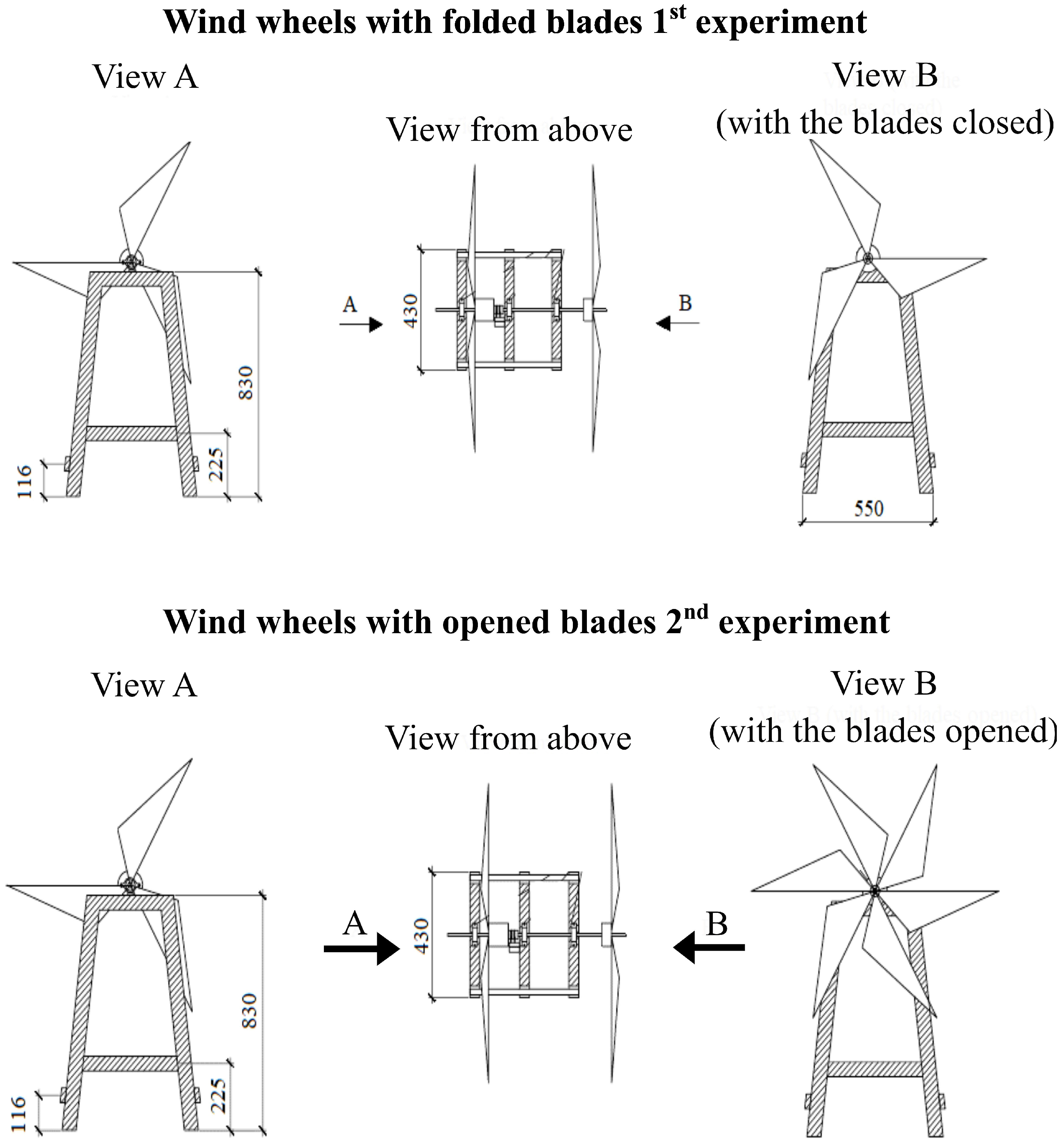
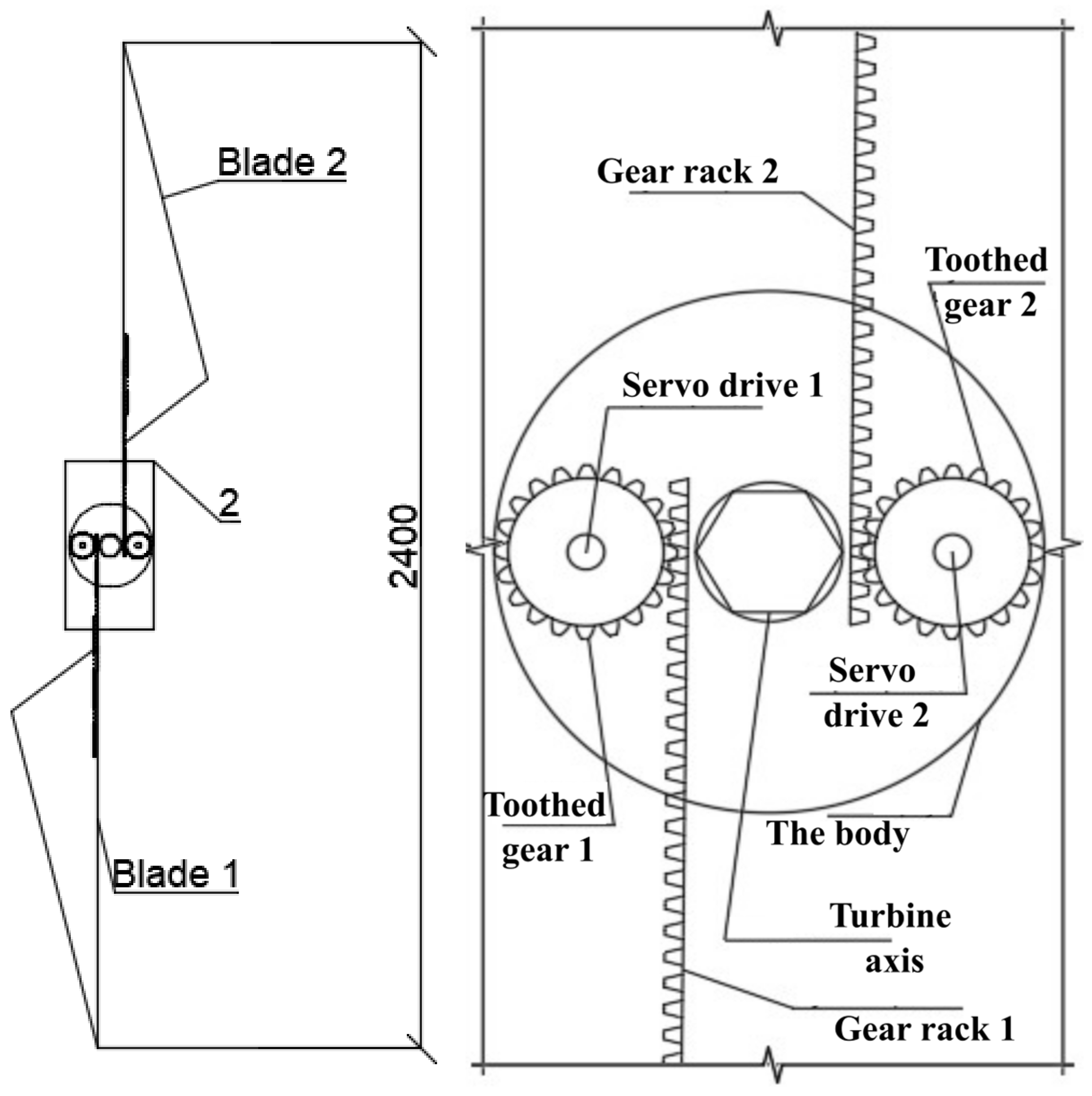
In accordance with our project objectives, project certification was advanced for a laboratory-scale sample of this explicit wind turbine. The general scheme of the dual wind wheel design, showing the rotating inductor and generator armature, is shown in Figure 1 for both configurations: folded (non-extended) and open blades (extended).
The device’s project comprises 2 “wind wheels”, 1 linked to the stator coil and the 2nd to the blade bloc, a metal base, and a current gathering system. Throughout the trials, a laboratory-scale investigational model and a semi-industrial sample were utilised. The investigational inquiries established the notional upsurge in the electrical energy generation. In rehearsal, the projected project is envisioned for high-efficiency electrical energy manufacture at low wind rapidity.
Table 1 demonstrates the industrialised requirement of project certification for the assemblage of this precise wind farm project.
Numerical modelling results guided the development and construction of the laboratory-scale model. This model supported subsequent experimental studies and served as the basis for the prototype.

2.2. Assembly and Experimental Setup

As shown in the project layout revealed in Figure 1, the counter-rotating wind turbine was fabricated. A metallic tube having dimensions of (20 × 20 mm) was used as the supporting frame. Bearings were installed on the upper section of each pillar to ensure smooth axis rotation. A dielectric coupling element (tube with expansion) equipped with copper contact rings was attached to the generator. These rings were soldered to ensure stable electrical connection during rotation. Two rotor systems were manufactured, each consisting of three blades (polymer-made, 0.5 m length). In order to achieve counter rotation, the blade sets were configured with opposite angles of attack.
One rotor was mounted directly on the generator shaft, while the other was attached via an intermediate disk (200 mm in diameter). All components were assembled to ensure continuous electrical connection and sufficient mechanical rigidity during operation. The output wires (lead wires, approximately 1–1.5 m in length) were soldered to the slip contacts to ensure connection with the measuring instruments.
Figure 2 shows the final “laboratory model” and the key basics of the planned “wind turbine”. The main principle of the proposed system is the increase in relative velocity between airflow and blades, resulting in enhanced energy extraction.
Three configurations were used and compared when measuring the start-up (cut-in) wind speed: a single rotor with three blades, a dual counter rotating rotor, and a modified blade distribution. All measurements were conducted under identical conditions, and the cut-in speed was recorded for each case.
For the preliminary laboratory experiments, a “wind generator” with counter-rotating wind helms was utilised, as shown in Figure 2. This design was obtained by modifying the conventional wind turbine configuration and adding a second wind wheel rotating in the opposite direction within the same airflow [7,35,38].
The experimental tests were conducted in a controlled laboratory environment using an axial airflow to simulate different wind speeds. The wind velocity was gradually increased within the operational range of 5–10 m/s. The wind rapidity was obtained with the help of a numerical anemometer positioned upstream of the turbine rotor (GT8907 Digital Multifunctional Anemometer). The rotational speed was measured by means of a digital tachometer (DT-2234C+ Digital Laser Photo Tachometer). The generated voltage was measured by means of a voltmeter (3-digit LED display, operating voltage from DC 3.5 V to 30 V). The current was recorded by means of a digital AC ammeter. All measuring instruments were selected according to the operational prototype range and calibrated in accordance with the manufacturers’ specifications.

2.3. Experimental Configurations

2.3.1. Progress of a Model of the Wind Motorised Portion of a “Wind Turbine” Built on Two Wind Helms with Specifics of the Project of the Blade Dispersal Device

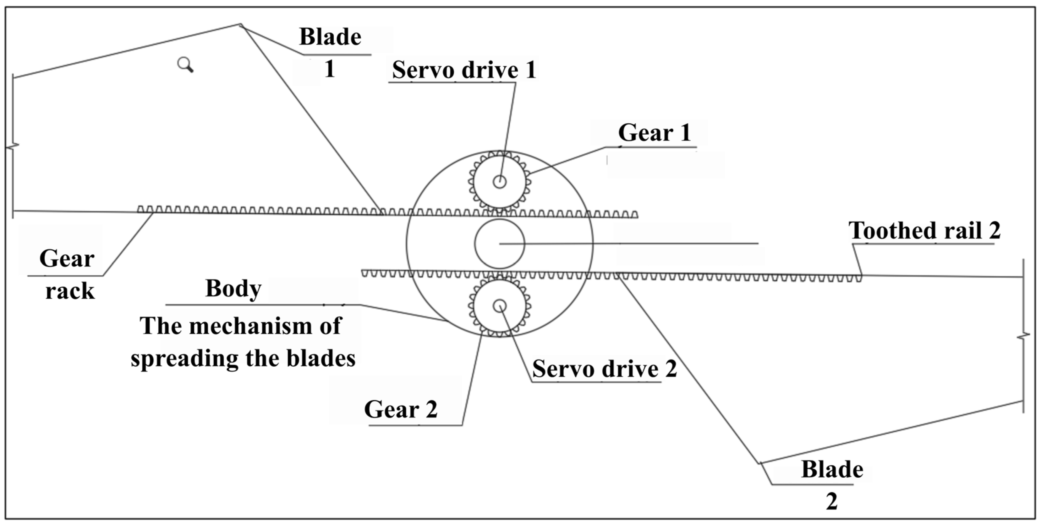
The device of edge dispersion contains numerous main operational mechanisms. All the specifics of this project can be separated into 2 key parts, the electric and motorised subsystems.
The electric tour comprises: 2 servo motors and blunder links.
The motorised cable comprises: 2 jagged bars, two notched mechanisms, and a key mechanical edge.
Organisationally, the device is as follows:
(1)
The device is furnished with 2 servomechanisms, which are motorised from a 220 V source through blunder links.
(2)
At the tops of the servo shaft, mechanisms are static, which convey a rotating wave to the equipment frame by frame and trap broadcast.
(3)
The jagged frames adapt the rotating wave into direct wave.
(4)
An edge is involved in the tackle frame, and at the instant of changing the rotating wave into translational wave, the edge spreads to a predefined location strongminded by the project.
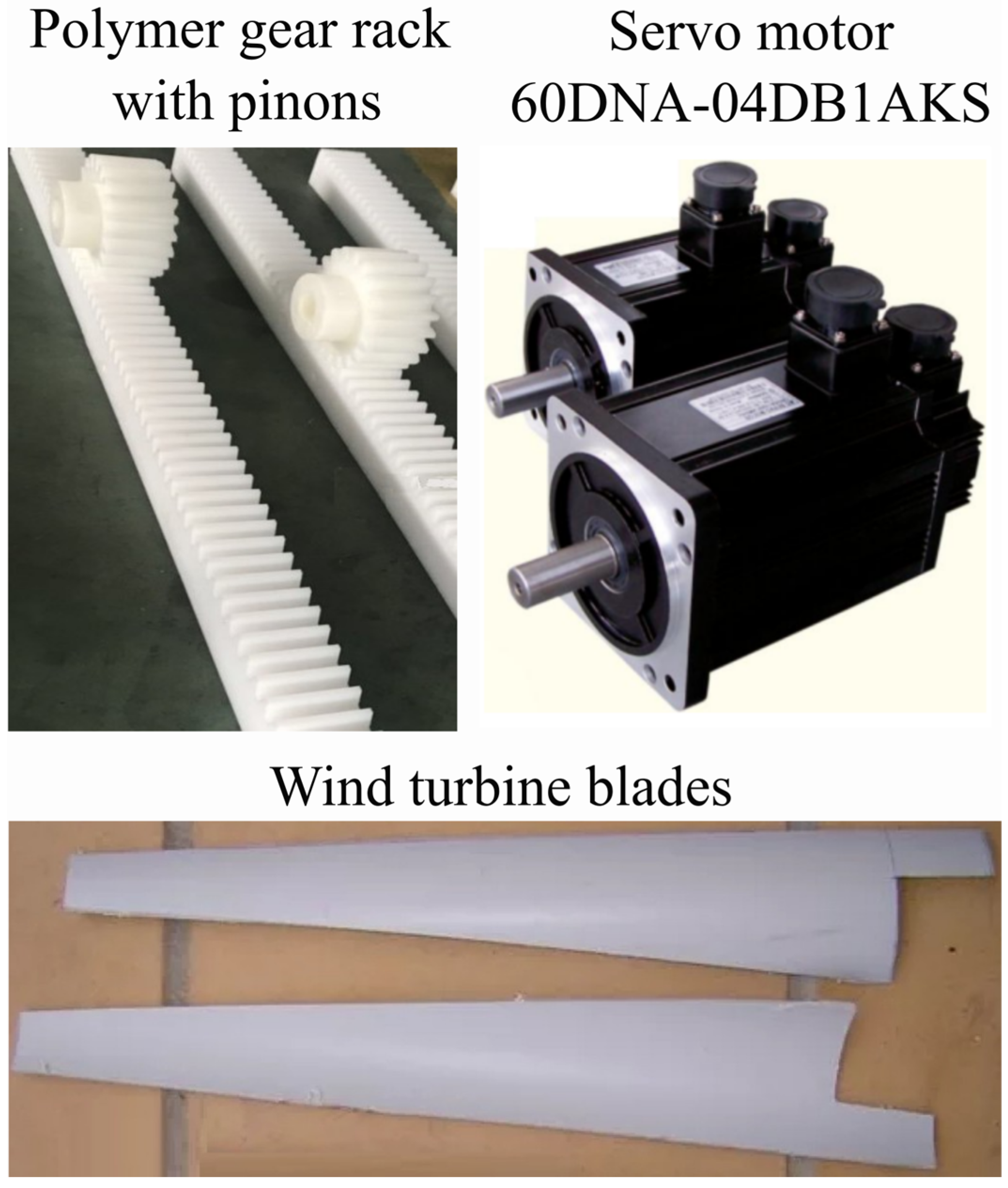
In this project, a polymer-made frame was utilised as the tackle frame to abridge the manufacturing. A polymer tackle helm was similarly utilised in the wind turbine assemblage. Metal mechanisms can be efficiently substituted by polymer constituents due to their high current motorised asset and appropriateness for frivolous constructions. Figure 3 displays the polymer tackle frame furnished with a notched apparatus and the “60DNA-04DB1AKS servo motor”.
The model “60 DNA-04 DB 1 AKS servo drives” was utilised in the edge postponement device. These energies were designated because of their compressed extent, small mass, and constructive practical features. These servomechanisms use perpetual electromagnets on the blade, which make an electromotive force (EMF) in the stator coil winds. Moreover, they bargain high placement correctness. Giving the constructer’s stipulations, the tube spot blunder is only 2 angular minutes.
These servomechanisms are fully enclosed and equipped with an auto-refrigerating system, which allows long-term operation with minimal maintenance. The wind turbine blades are manufactured from high-strength polymer materials and are carefully designed to attain the compulsory angle of bout. The industrialised edges are exposed at the bottommost region of Figure 3.
To provide a more comprehensive understanding, a detailed sketch of the completely collected wind generator is shown in Figure 4. It shows the entire blade-spreading mechanism, where it is housed inside the rotor cap.
Grounded on the industrialised model of the “wind turbine” motorised system, which incorporates two counter-rotating wind wheels and a detailed blade extension mechanism, the experimental study was conducted.

2.3.2. The First Experimental Setup for Non-Extended Blades

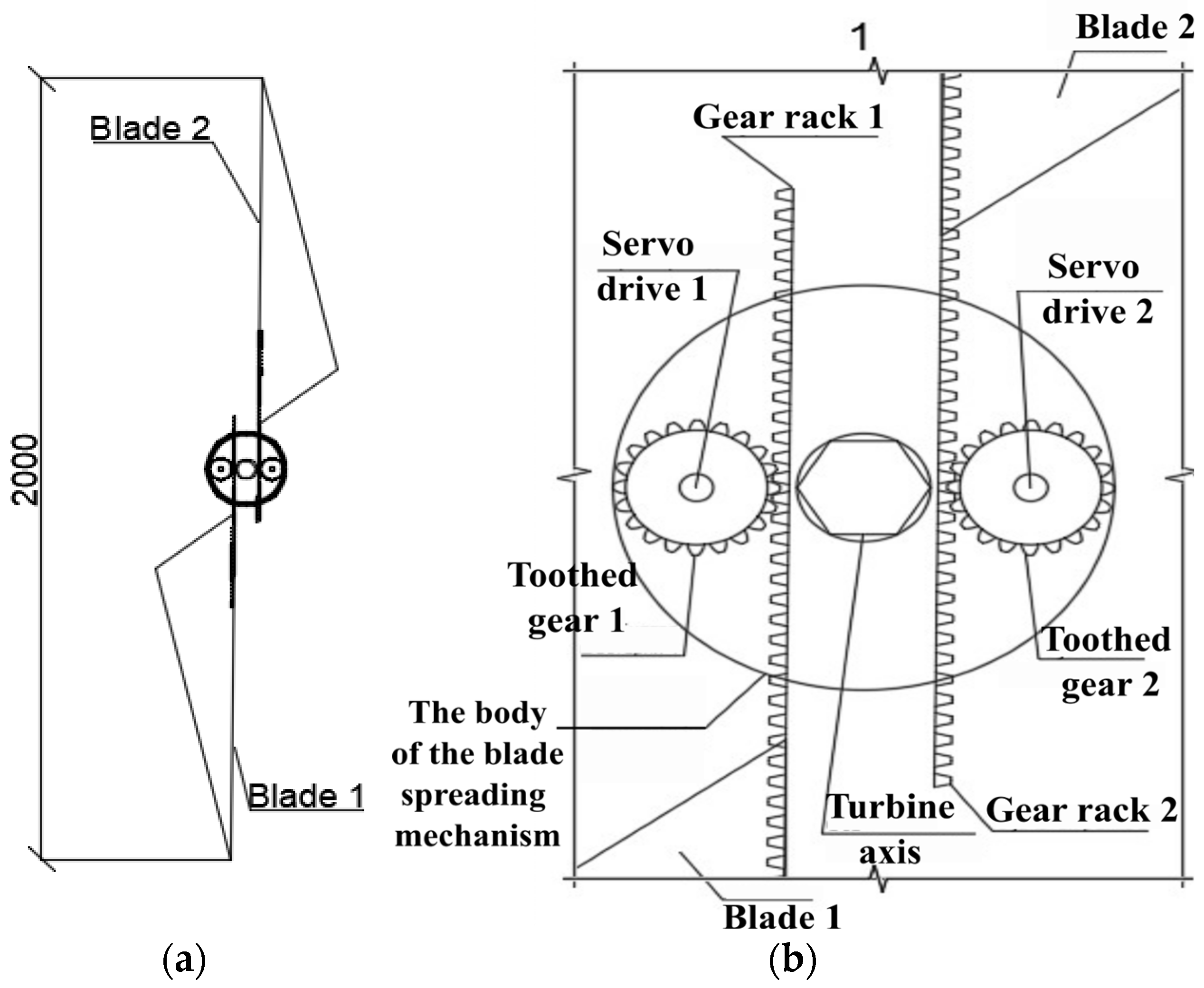
The experimental setup throughout the 1st test is shown in Figure 5. To enable additional examination and the development of performance features, the rotational rapidity of the wind wheels was measured at diverse wind rapidity.

2.3.3. The Second Experimental Setup for Extended Blades

In the second experiment, tests were carried out on the “extended-blade” arrangement shown in Figure 6. Theoretically, the generated current and voltage are expected to increase because the effective lever arm of the applied aerodynamic force becomes longer at the same wind speed.
In both experimental setups, 5 dimensions were engaged to each wind rapidity. The experimental installation used in the second experiment is shown in Figure 6.
By equivalence with the 1st test, the spin rapidity at diverse wind rapidity was measured.

3. Results and Discussion

3.1. Set-Up Presentation

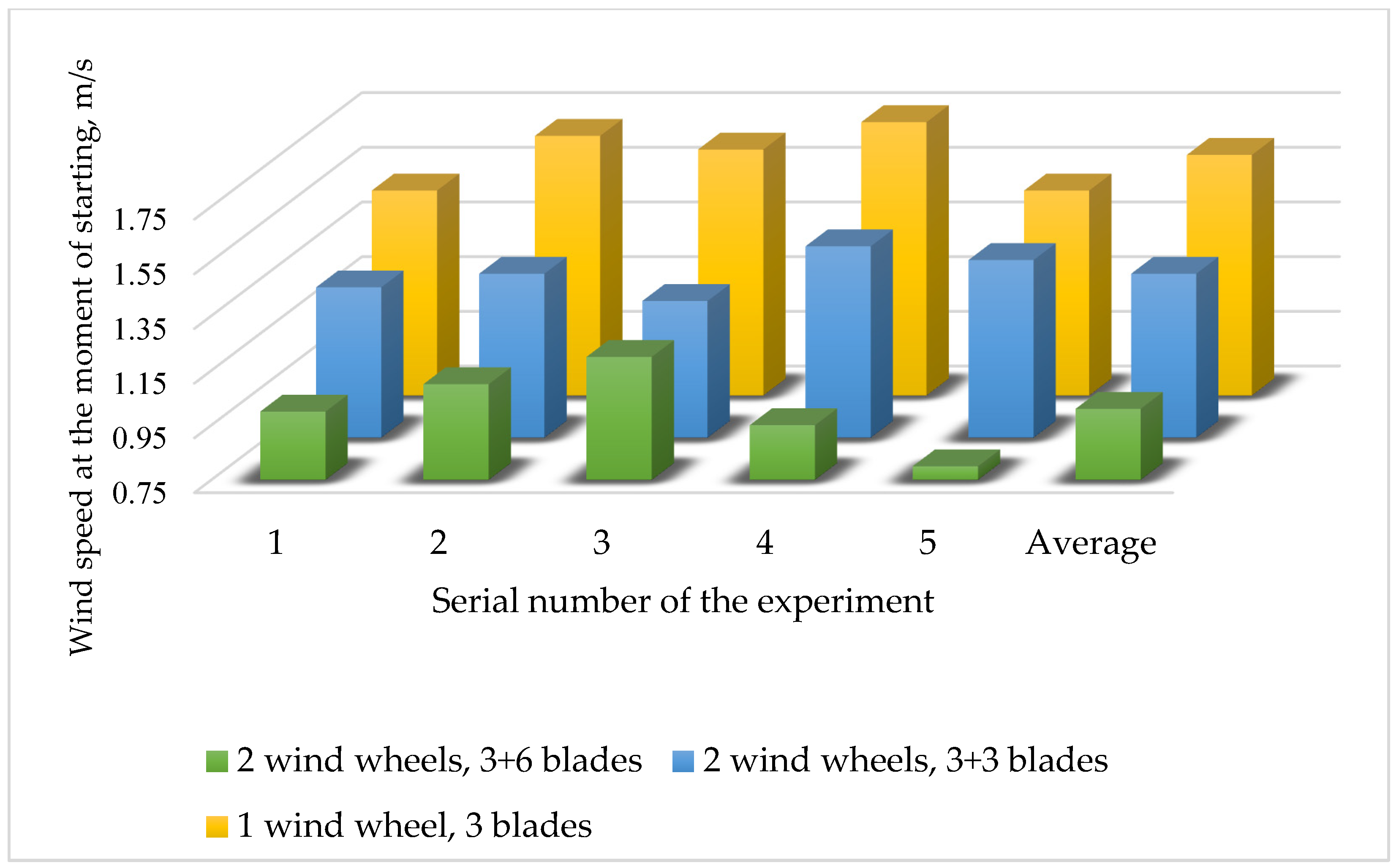
Figure 7 displays the outcome of “wind wheels” quantity (and the conforming quantity of edges) on the setup features of the turbine. As shown in Figure 7, there is a strong association amongst the quantity of edges intricated and the preliminary rotating rapidity of the “wind wheel”. When one solitary ”wind wheel” was utilised (3 edges), the usual preliminary rapidity was 1.63 m/s. When both “wind wheels” with three edges each were dynamic, the normal preliminary wind rapidity reduced to 1.35 m/s, which was about 17% more inferior than the solitary “wind wheel” case. In the third shape, the kind of dimension was made when three edges were arranged on one of the “wind wheels”. This prearrangement attained the lowermost regular preliminary wind rapidity of 1.01 m/s, which was more than 25% more inferior than the second situation and more than 38% more inferior than the “single-wheel” configuration.
These results show that the increase in the blades’ number and the use of the two counter-rotating wind wheels decreased the “cut-in” wind rapidity (wind rapidity compulsory to twitch the turbine).
Table 2 shows the recorded values for the three configurations used in this study, along with the number of trials, errors, and deviation errors.

3.2. Airflow Analysis

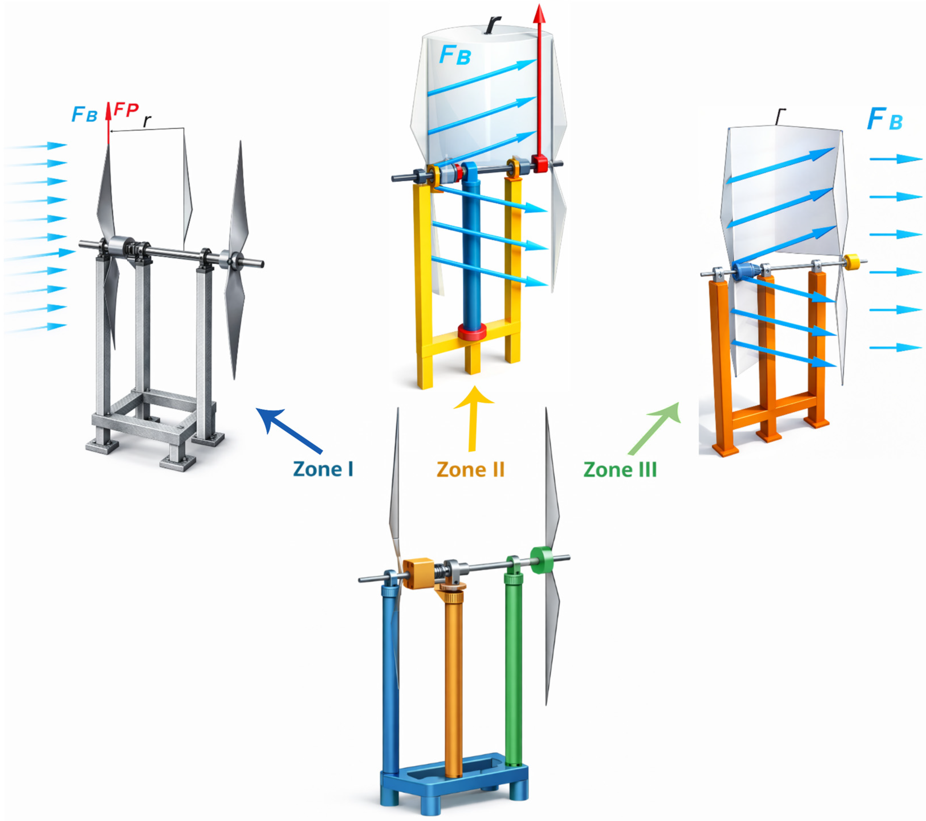
When operating the laboratory-scale wind turbine, three characteristic airflow zones were formed, as shown in Figure 8. These zones governed the aerodynamic interaction between the counter-rotating wind wheels and significantly influenced the efficiency of energy conversion. These three zones thus can be defined as follows:
(1)
The upstream region, where the airflow is located before its interference with the first “wind wheel”;
(2)
The intermediate or “inter-rotor” region, located between the two wind wheels;
(3)
The downstream region, situated after the second “wind wheel”.
For the upstream region, the airflow in this region does not vary from the anterior part of a conventional “wind generator”. The airflow remains undisturbed and exhibits a linear velocity profile. When the airflow transfers on the dynamic bolt of the “wind wheel”, the edges form slogs. Given “Newton’s 3d law”, the power acting on the edges, which is transformed into the rotating wave of the propellor, is equivalent to the power of slog of the edges. These two forces are focused on conflicting orders. A ”wind generator” with a parallel axis of spin (utilised in scientific study) gets its spin from the elating force Fn, which has a course of 90°, comparative to the course of wind flow [35].
In the intermediate or inter-rotor region, there is a winding of airflows transitory over the part of revolution of the first “wind wheel”. Due to the counter-rotating configuration, the airflow undergoes a change in rotational direction before interacting with the second wind wheel. Scientifically, you can define the course of the airflow with reverse ciphers.
To assess the flow regime in the inter-rotor region, the Reynolds number (Re) was estimated using the following formula:
R e = ρ . v . D μ
where ρ is the air thickness, v is the comparative rapidity between the airflow and the edges, and D is the distance between the two rotors. The dynamic viscosity of the air is labelled μ. The calculated Reynolds number (Re) remained below the typical threshold for transition from laminar to turbulent flow in the investigated configuration. This supports the laminar flow to be predominant in the space between the counter-rotating blades. Yet, some localised turbulence may still occur.
At the instant of altering the course of drive, twirl constructions are made. These whirlpools harmfully touch the change in “wind energy” into “electrical energy”, meanwhile the second wind wheel does not obtain an equal even airflow, in contrast with the first wind wheel.
The third sector—downstream area—does not partake in energy making, since only the energy of the air flow passes there.
The amount of undeveloped wind energy is determined by the Betz limit [49]. The wind energy use rate is 0.593 (efficiency of energy extraction) [50], which is approximately 59% of the total wind energy that passes through the rotor swept area.
To fix the best detachment amid wind wheels, the investigational model was adapted to allow for the alteration of the inter-wheel detachment. The optimal separation was selected to maximise wind energy transfer (the distance at which the wind flow stabilises after passing through the first wind wheel and exerts the maximum possible impact on the second one [35]). Therefore, when calculating the power output of the system, it is necessary to consider that the second wheel receives less available wind energy than the first one by a factor of k [38].
This coefficient (k) depends on several parameters: the wind speed V (m/s); the air density ρ (kg/m3); the number of blades n; the wind wheel rotation speed v (rpm); and the distance between wind wheels l (m).
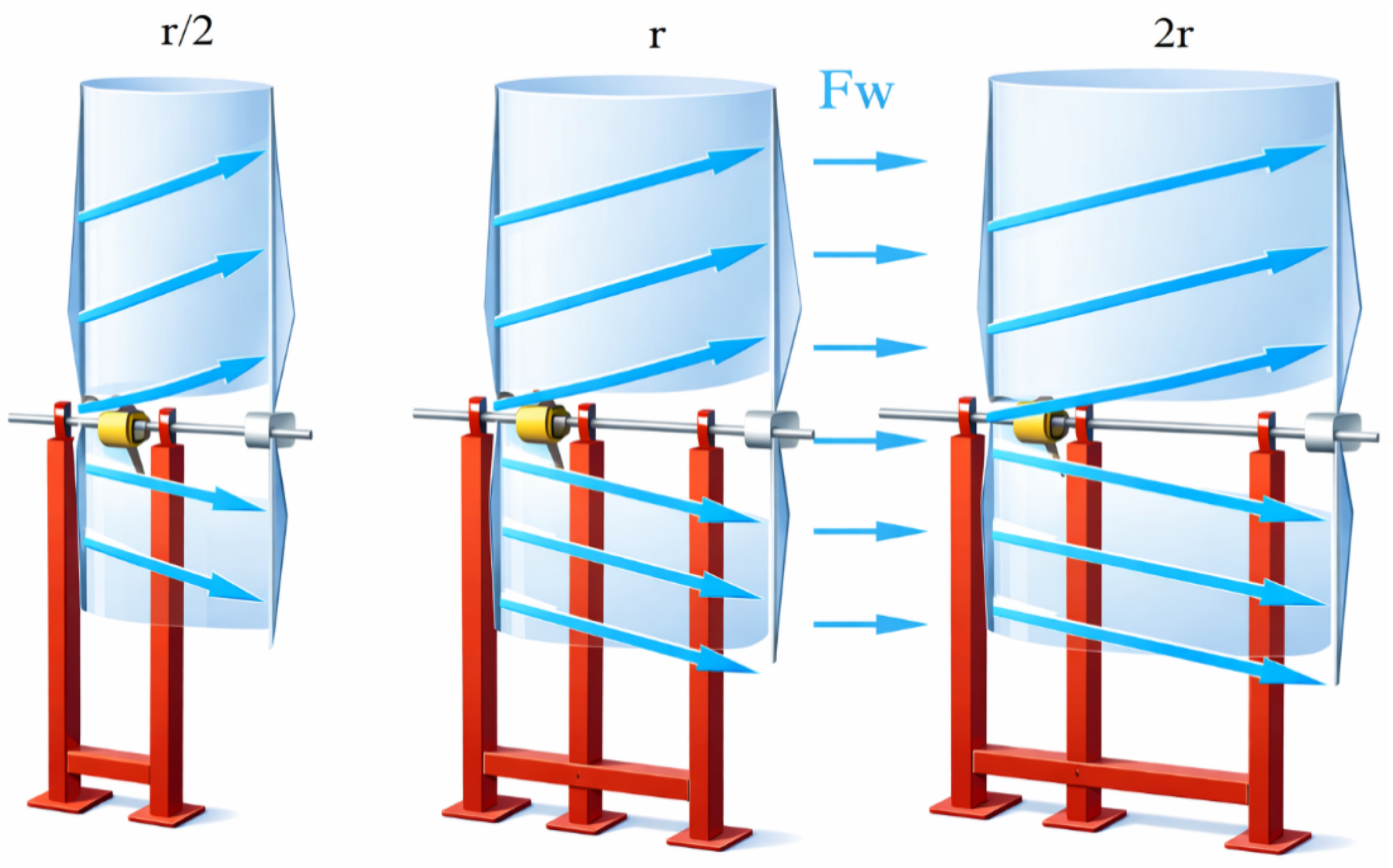
Based on the above, the distance between the wind wheels is the most practical parameter for optimising the system performance. Increasing the inter-wheel distance reduces the aerodynamic interaction between the two rotors. This occurs due to the delayed time of the distributed airflow from the first wind wheel to recover its original characteristics, which will really mark the spin of the second “wind wheel”. The flow of air power at diverse inter-wheel detachments is shown in Figure 9.
Under ideal conditions, the counter rotation of the stator and rotor could theoretically double the generated power. However, this is practically unattainable due to the influence of multidirectional eddy currents and other aerodynamic losses. Consequently, the constant of supplementary force created by the second wind helm has the next charge:
1 < k < 2.
Meanwhile, there is a straight relative relationship amid the wind energy captivated by the second wind wheel and the power created by the wind generator; it should be expected that the energy advance constant related to the counter-rotating arrangement Pww comparative to a typical wind generator Pw has the subsequent rapport:
Pww = kPw,
where k is the constant of the extra energy made because of the counter-rotating rotating scheme:
Pww—power production of the wind generator with counter-rotating wheels;
Pw—power of a typical single-wheel wind generator.
To confirm the theoretic worth of the constant of energy made by a wind generator with counter-rotating wind helms, the investigational labour was accomplished with the “wind generator model”, and standards obtained were examined.
The electrical power was calculated as
P = U × I
where voltage (U) and current (I) were measured simultaneously.
The straightened airflow enhances the aerodynamic forces on the edges of the second rotor, with subsequent higher rotational speed and greater electrical power output. The distance between the two wind wheels is a key design parameter affecting energy production. The results showed that the optimal distance is equal to one radius (r), corresponding to the diameter of a single wind wheel.
It must be noted that the aerodynamic flow field between the two counter-rotating wind wheels was not characterised quantitatively in this study. Detailed CFD simulations or flow visualisation experiments are recommended in future work to provide more insights into the wake interaction and vortex dynamics.

3.3. The Aerodynamic Features of Wind Helms with the Willpower of the Key Restrictions and Dials

This paper analyses an alternative wind turbine project, mainly, the outcome of descending (folding) edges on the force production of the laboratory-scale wind control enterprise. The all-out presentation attainable by means of wind helms with diverse widths was assessed. The width of the wind helm is nominated giving the valued force of the fixed generator. For low-power schemes, large-diameter blades are not required, as a comparatively small spin device is enough to indorse such an electric unit. In comparison, wind helms with greater ranges are characteristically used to power wind turbines of various kW levels.
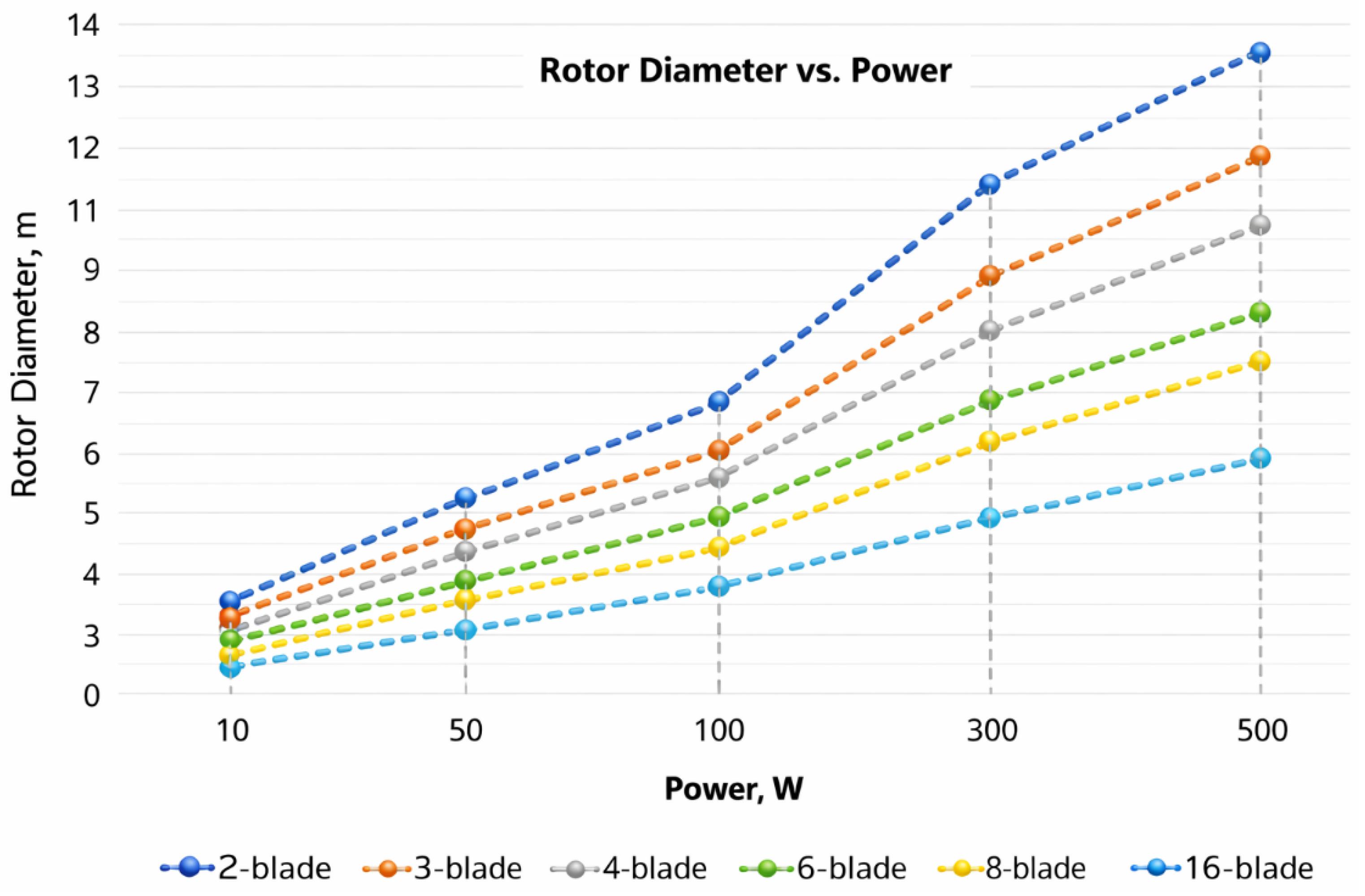
Figure 10 displays charts of the relationship of wind wheel width and the power created for different blade configurations.
As shown in Figure 10, an advanced number of edges permits the similar force production to be attained with a minor blade width.
Wind helms with two and three edges were examined in more detail, as they have the greatest cooperation amid aerodynamic presentation and general mass.
When the force upsurges from 10 W to 50 W, the width of the two-bladed wind helm upsurges by a reason of 2. This connexion is likewise detected for a three-bladed shape, though the preliminary edge span is better.
By overlaying the investigational statistics obtained with the descending edges project onto the statistics accessible above, it is hypothetically conceivable to evaluate the supplementary force made when the device is started. Meanwhile, the laboratory model was intended for about 60 W, and the investigational statistics for the two-bladed shape were scaled up. Seeing that the constant of dispersal the wind turbine is 1.2, it is conceivable to hypothetically make a prediction for creating growing force. To establish the statistics for the gathered and feast edge shapes of the laboratory model, Table 3 was accumulated, and the subsequent statistics were obtained.
As shown by the considered results, preliminarily from 30 W of made power, the “wind generator” with lengthy (feast) edges shifts to a higher power output level compared to the standard design. For example, at an initial radius of 3.44 m, producing an output of 30 W, extending the edges increases the range to 4.13 m and raises the probable power output to 40 W. This design has a non-linear inclination, which permits us to determine that this project hypothetically permits an upsurge in electric energy making.
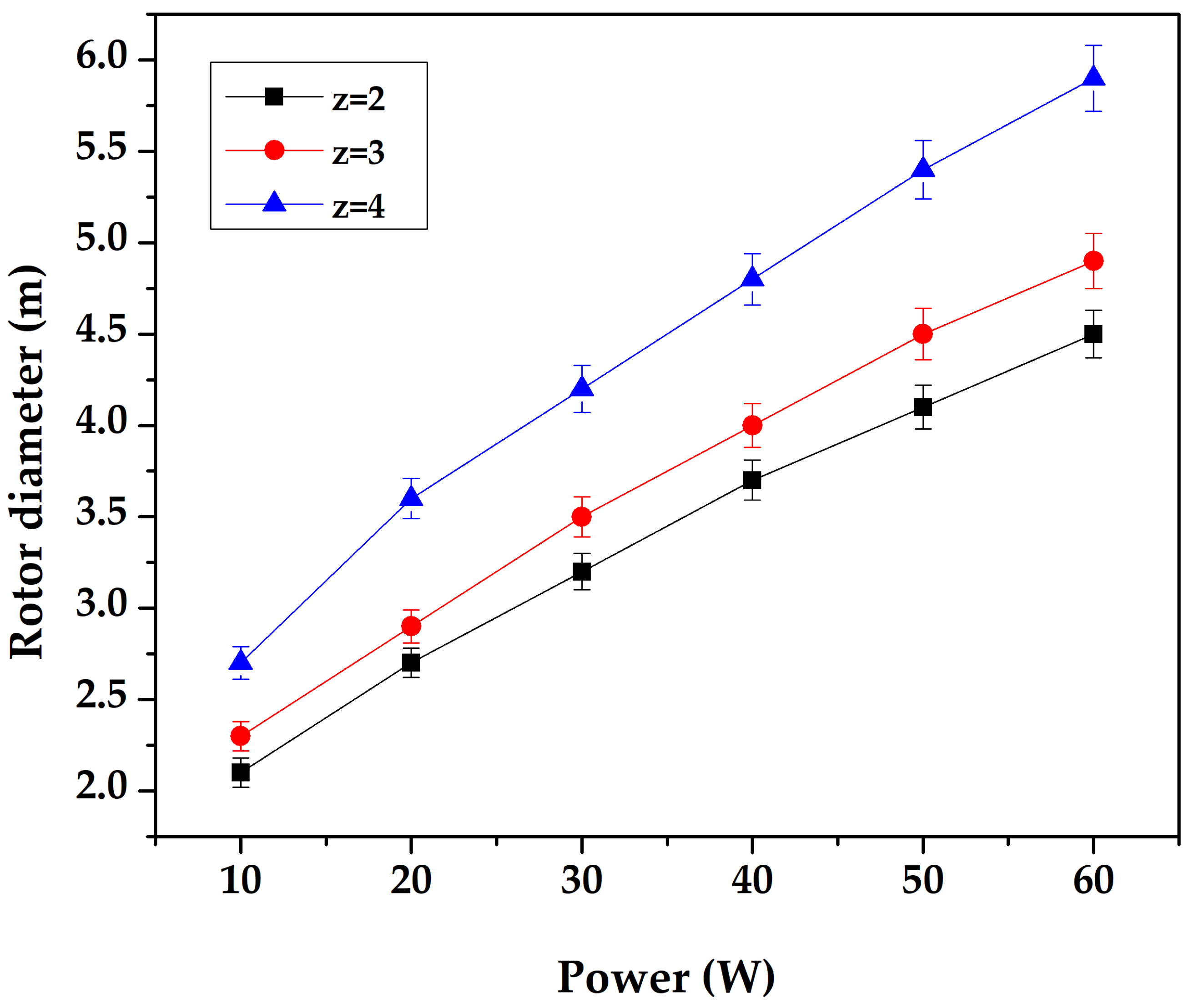
To examine this relationship in more detail, the power output of a two-bladed wind generator was examined at diverse points on the descending device, as exposed in Figure 11.
Hypothetically, the proposed wind turbine project offers clear practical potential. The results demonstrate that a three-fold increase in power output can be achieved by increasing the diameter of the wind wheel by a factor of 1.5.
Figure 11 displays the requirement of rotor diameter on generated power for different numbers of blades (z = 2, 3, and 4). The comparison was carried out under identical operating conditions. The discrepancy observed between the curves is attributed to variations in rotor structural strength and aerodynamic loading. Increasing the quantity of edges enhances the structural strength of the rotor and improves torque generation under comparable operating conditions. Consequently, a larger rotor diameter is required to achieve the same power output level.
To validate the obtained data, practical modelling was conducted on an experimental prototype. Modelling on an investigational model of a “wind farm” of a distinct project was led in laboratory settings, and the outcomes gained are measured and are established in the subsequent sections.

3.4. Experimental Results of the Designed Wind Farm with Non-Extended Blades

The first experiment was led on the investigational arrangement with the edges in the non-spread place, as revealed in Figure 5. This provided baseline performance characteristics for comparison with the results of the second experimental setup.
To ensure accuracy and minimal measurement errors, five repeated dimensions were engaged at each level of wind rapidity. Table 4 displays the normal standards, to avoid statistical confusion.
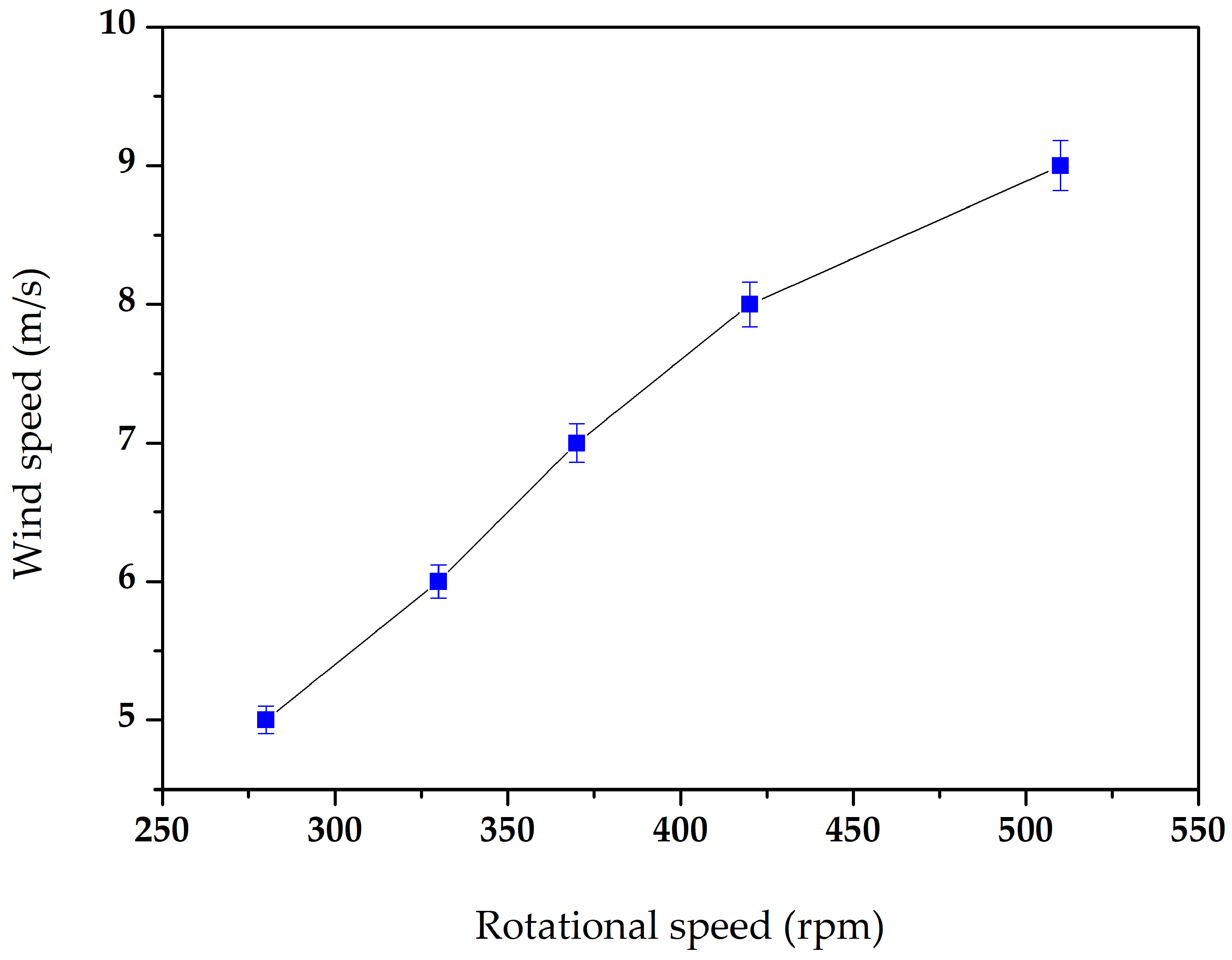
Based on the measured rotational speeds, the relationship between rotor speed and wind speed was determined. As shown in Figure 12, the rotational speed increases almost linearly with wind speed. The minor deviations from this linear pattern are attributed to instrument error and imperfect experimental conditions.
When gaging the rapidity of spin, the limits of current (I) and voltage (U) were concurrently slow. The outcomes obtained from these experimentations are shown in Table 5.
Based on the data obtained (Table 5), the connection between the blade turning rapidity and the current and voltage used was investigated.
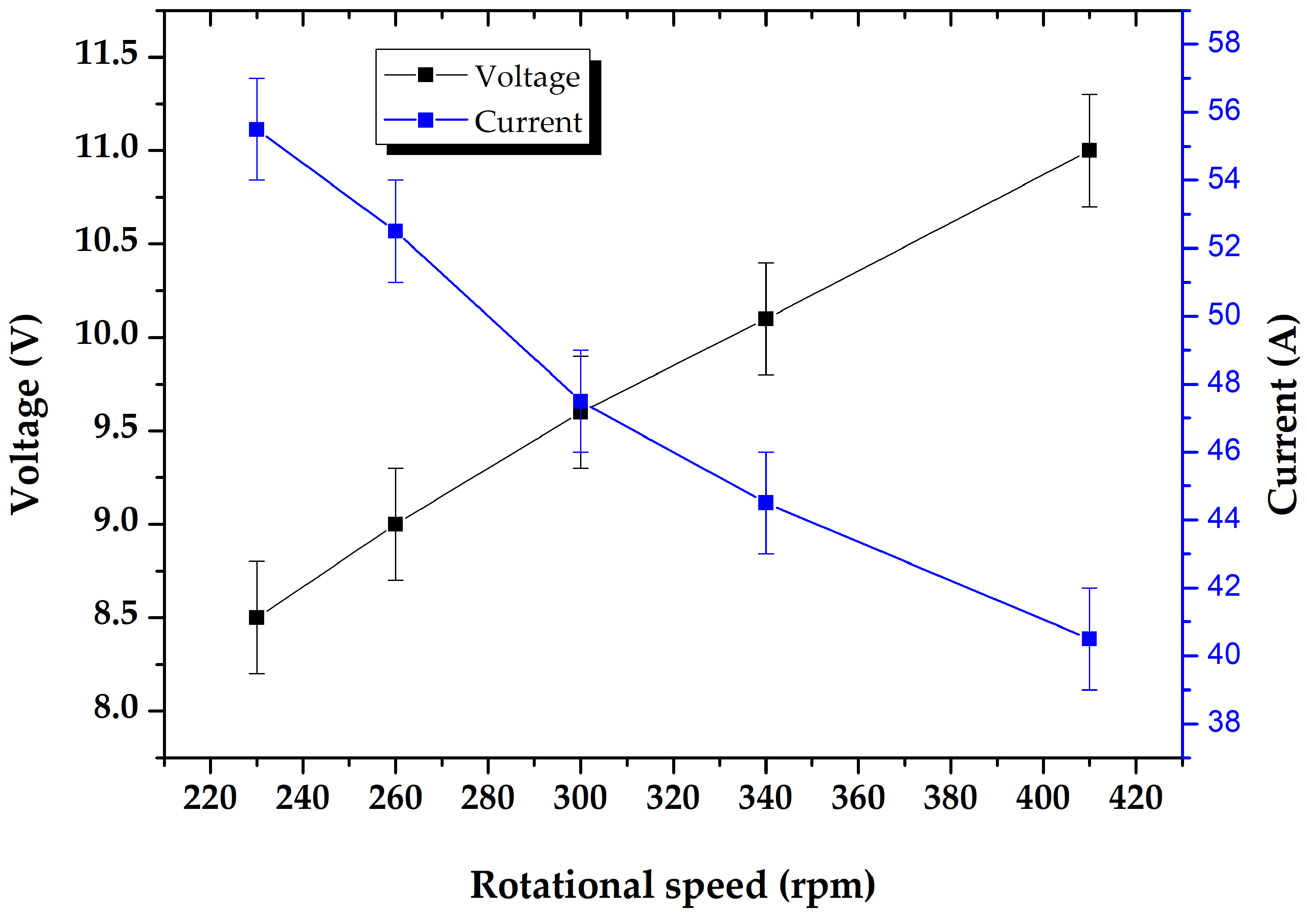
As revealed in Figure 13, at the commencement of the dimensions, when the wind rapidity reached 5 m/s (which matches to a spin rapidity of 230 rpm), the noted voltage was about 8 V. As the rotating rapidity was additionally augmented, the power continued to increase. In comparison, the current made is contingent mainly on the produced voltage, and, given Ohm’s law, it has conflicting design from the spin rapidity. When the produced voltage upsurges, the current decreases.
Given the fallouts obtained, an upsurge in voltage generation is predictable in the next trial. Since the project with lengthy edges (augmented range of the wind helm) forecasts an advanced spin rapidity, higher voltage output is expected.

3.5. Experimental Results of the Wind Farm with Extended and Sliding Blades

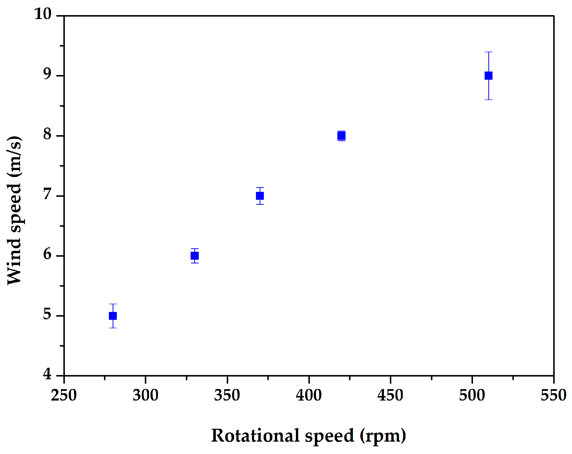
Figure 14 shows the relationship between rotor speed and wind speed. The rotational rapidity dimensions display that, at similar wind rapidity, the rotor with spread blades achieved an average 20% higher rotational speed compared to the standard configuration. This result confirms that the wind generator with spread blades provides higher rotational performance under the same wind conditions.
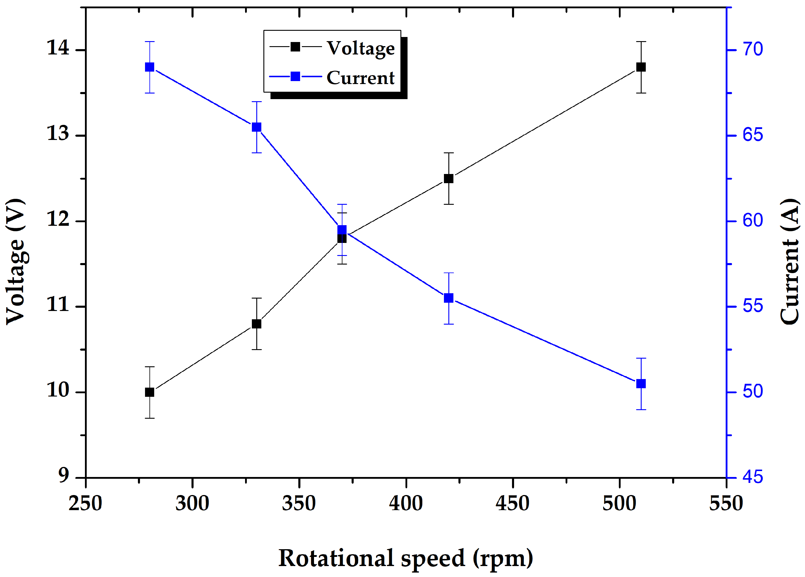
Figure 15 presents the association between rotating rapidity and the generated voltage and current.
The results presented in Figure 15 indicate that the tendency of direct requirement of voltage and current endured from the first trial, but the produced pointers augmented.
A thorough contrast of the outcomes obtained throughout the experimentations is assumed in the next subcategory.

3.6. Assessment of Investigational Features of the Non-Extended and Extended Systems

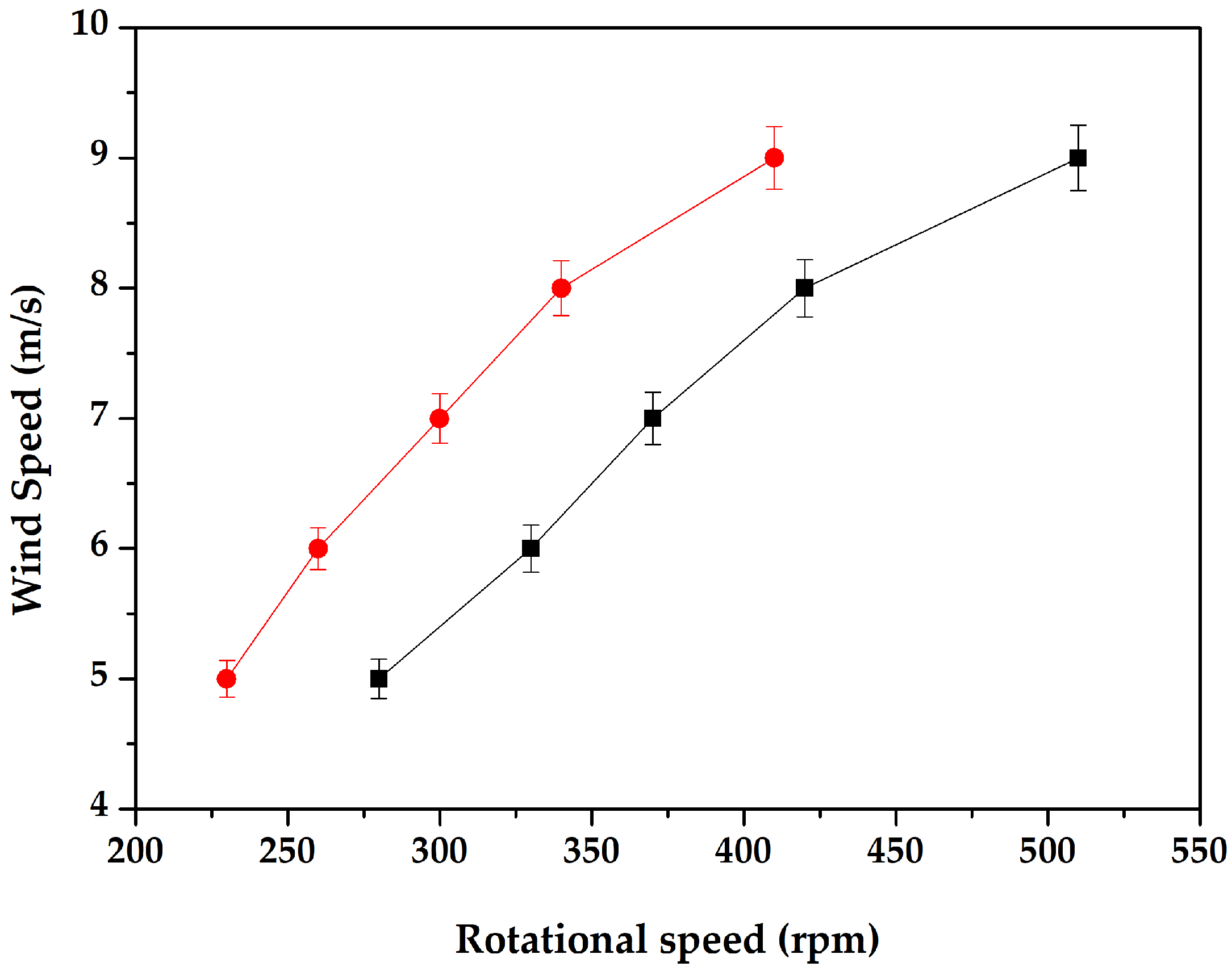
When likening the features obtained throughout the first and second trials, a summary Figure 16 was made.
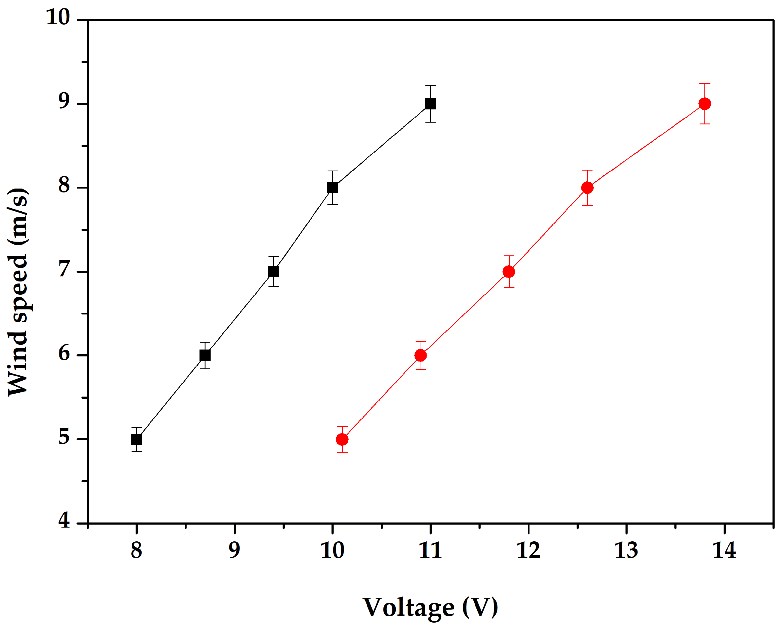
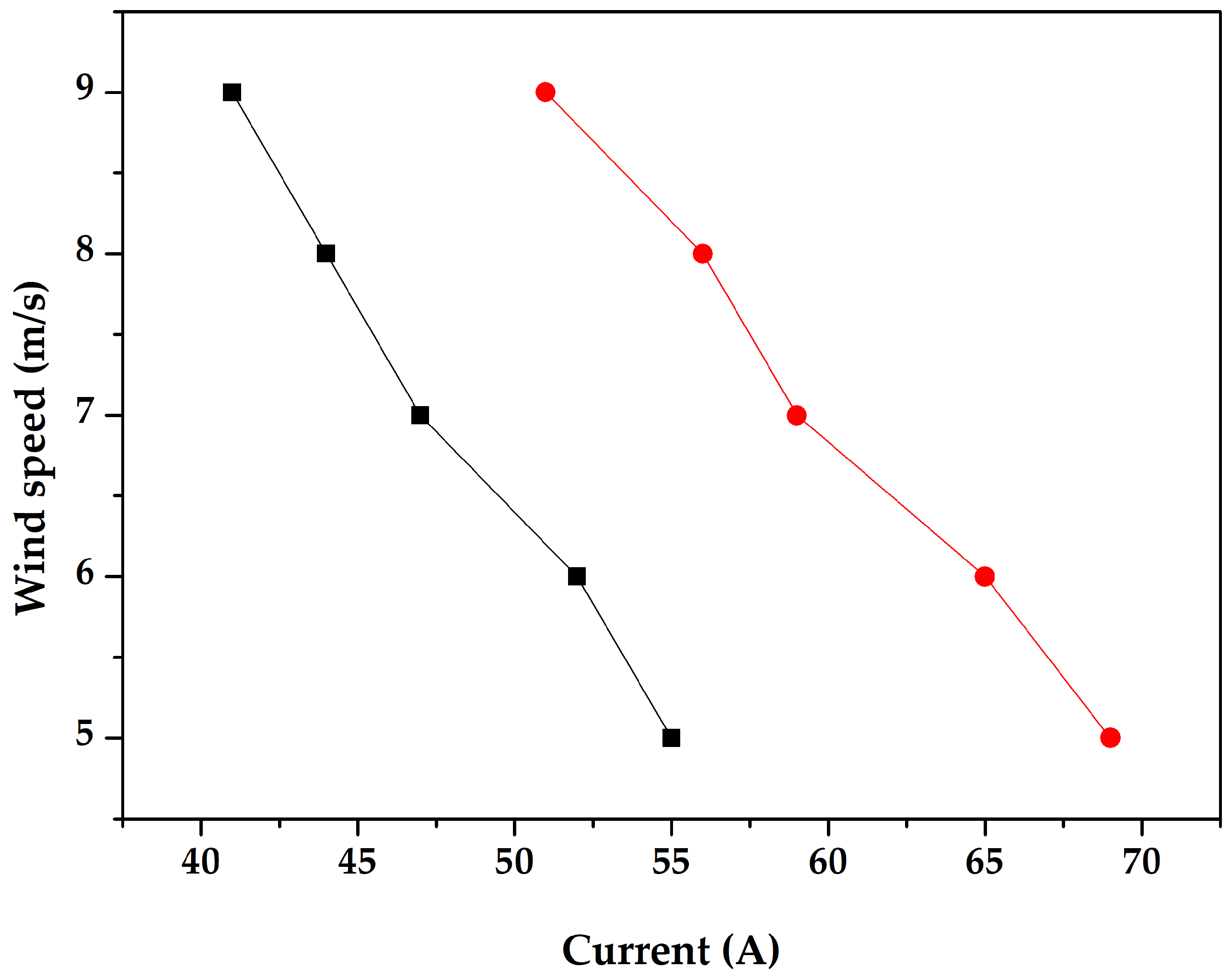
Charts likening the features of the first and second trials are made to vividly show the statistics obtained throughout the study. Figure 16 displays spin rapidity contrast graphs; Figure 17 displays voltage contrast graphs; and Figure 18 displays present contrast graphs.
The concluding investigational outcomes display that the greatest generation charges are detected in a wind maker with six edges on the blade and three edges on the stator coil. Table 6 compares the electrical generation characteristics (voltage and currents) of different rotor–stator blade configurations under both studied conditions. In all tested configurations, the measured output in the extended blade design configuration was higher than under the non-extended blade configuration.
Wind turbines with two multidirectional (counter-rotating) wind helms were examined in this article. Given the results obtained throughout applied trials, the constant of energy produced by a wind generator with counter-rotating wind helms was found within the range of 1.5–1.6, as shown in Table 6. The additional power gain provided by the counter-rotating experimental setup was quantified by the k coefficient. As mentioned in the methodological section previously, Pw is the electrical power output of the baseline (non-extended blades) and Pww is for the two counter-rotating wind wheel setup. The obtained values of k ranged consistently between 1.55 and 1.56, as shown in Table 6. The experimentally validated range confirms the theoretical assumption, stating that the additional gain coefficient should be 1 < k < 2. While remaining below the ideal values of 2, these lower values are due to aerodynamic interactions between the rotors.
In agreement with the investigational revisions, the hypothetical forecasts were established, and the correctness of the constant was augmented. However, further research is required to fully understand the behaviour of counter-rotating wind turbine systems. “Wind turbines with counter-rotating wind helms” are not completely disclosed. This type of counter-rotating wind turbine presents significant opportunities for future research and technological development. The outcomes advise that the cumulative quantity of blade edges may enhance electrical output within the investigated operating range.
Our results collectively show that the innovative blade with a counter-rotating wind wheel configuration reduced the cut-in wind rapidity. The outcome of the wind rapidity on rotor rotational speed in all cases showed a progressively increasing trend. In the meantime, the extended-blade configuration has shown a higher performance, as noted by the decreased cut-in wind speed compared to the fixed-blade configuration. This behaviour is probably attributed to the increase in the effective swept area and the enhancement in the aerodynamic torque. Increasing the blade radius also improves the interaction between airflow and the rotor surface. This will result in an increased generated voltage with increasing wind speed, which is directly related to the direct coupling between the rotor and the electrical generator in a counter-rotating motion.
Furthermore, the comparative analysis shown in Figure 10, Figure 11, Figure 12, Figure 13, Figure 14, Figure 15, Figure 16, Figure 17 and Figure 18 confirms that the counter-rotating design improves the airflow and the rotational behaviour, which leads to improved operational characteristics residing in a reduced cut-in speed, which is the main focus of this paper: a design that can be used in small wind turbine systems for agricultural implementation.

4. Conclusions

Grounded on the presented data analysis, the subsequent brief assumptions can be proposed as follows:
  • Extendable blade design efficiency.
The results showed that the proposed wind turbine configuration with extendable blades improved the startup and rotational speeds of the system. Compared to the fixed-blade configuration, an approximate 20% enhancement was measured in rotor rotational speed at identical wind velocities. This expands its applicability in regions with low and moderate wind environments.
2.
Electrical parameters and power.
A direct relationship was observed between rotor rotational speed and generated voltage.
Stability: A decrease in current strength with an increase in voltage was due to the operation within the valued control of the generator (~0.7 kW), which confirmed the correct operation of the electrical system without overloads.
3.
Operational adaptability and monitoring.
The use of active parameter control systems (dynamic regulation) showed adaptive aerodynamical control under varying wind conditions. This allowed the turbine to be adapted to the current wind conditions in real time, ensuring constant energy production. However, additional investigations under real operating conditions are required to evaluate long-term performance.
4.
The potential of counter rotation.
The counter-rotating design demonstrated improved startup performance and higher power output, likely associated with improved airflow use, and contributed to increased energy conversion.
The generation enhancement coefficient k was in the range of 1 < k < 2.
The mathematical dependence was expressed by the formula Pbb = k Pb.
Experimental data confirm that the proposed special design (sliding blades + counter rotation) effectively solved the problem of generating energy in conditions of low wind activity, increasing the overall efficiency of the installation under laboratory conditions. Further experimental validation under broader operating conditions is necessary for future studies.
The present study’s results provide preliminary experimental validation of the counter-rotating design with extendable blades.
Although the laboratory prototype showed promising performance, scaling the system to industrial power levels could introduce several mechanical challenges. The counter-rotating configuration will induce additional loads on the bearing supports on both the rotor and stator shafts. Additionally, further issues could rise, including misalignment due to differential thermal expansion values, increased radial and axial loadings, and pulsating mechanical moments. All these factors together will accelerate bearing wear and reduce system reliability. Our findings show promising aerodynamic and electrical characteristics, but further investigations are needed. Large-scale testing, long-term operational evaluation, and advanced aerodynamical simulations are necessary to optimise the system for practical uses in real agricultural fields.

Author Contributions

Conceptualisation, S.I.; methodology, S.I. and F.B.; software, D.S. and J.N.; validation, D.K. and G.N.; formal analysis, S.I., F.B. and G.N.; investigation, D.S. and D.K.; resources, S.I. and G.N.; data curation, F.B. and G.N.; writing—original draft preparation, S.I., F.B., G.N. and D.S.; writing—review and editing, S.I.; visualisation, S.I., D.K. and J.N.; supervision, S.I.; project administration, S.I., F.B. and G.N.; funding acquisition, S.I., F.B., D.K. and G.N. All authors have read and agreed to the published version of the manuscript.

Funding

Participation in the research of by the authors S.I., F.B., and G.N. was funded by the Science Committee of the Ministry of Science and Higher Education of the Republic of Kazakhstan (Grant No. AP32715297, 2026).

Data Availability Statement

The data presented in this study are available upon request from the corresponding author.

Conflicts of Interest

Author Damir Kayumov was employed by the company Light Engineering LLP. The remaining authors declare that the research was conducted in the absence of any commercial or financial relationships that could be construed as a potential conflict of interest.

References

  1. Petrenko, Y.; Denisov, I.; Koshebayeva, G.; Biryukov, V. Energy Efficiency of Kazakhstan Enterprises: Unexpected Findings. Energies 2020, 13, 1055. [Google Scholar] [CrossRef]
  2. National Statistics Bureau of the Agency for Strategic Planning and Reforms of the Republic of Kazakhstan Fuel and Energy Consumption in Households in the Republic of Kazakhstan. Available online: https://stat.gov.kz/ru/industries/business-5statistics/stat-energy/publications/5188://stat.gov.kz/ru/industries/business-statistics/stat-energy/publications/ (accessed on 30 June 2023).
  3. Osman, A.I.; Chen, L.; Yang, M.; Msigwa, G.; Farghali, M.; Fawzy, S.; Rooney, D.W.; Yap, P.-S. Cost, Environmental Impact, and Resilience of Renewable Energy under a Changing Climate: A Review. Environ. Chem. Lett. 2023, 21, 741–764. [Google Scholar] [CrossRef]
  4. Dalei, N.N.; Gupta, A. Adoption of Renewable Energy to Phase down Fossil Fuel Energy Consumption and Mitigate Territorial Emissions: Evidence from BRICS Group Countries Using Panel FGLS and Panel GEE Models. Discov. Sustain. 2024, 5, 52. [Google Scholar] [CrossRef]
  5. Jianzhong, X.U.; Assenova, A.; Erokhin, V. Renewable Energy and Sustainable Development in a Resource-Abundant Country: Challenges of Wind Power Generation in Kazakhstan. Sustainability 2018, 10, 3315. [Google Scholar] [CrossRef]
  6. Ministry of Energy of the Republic of Kazakhstan. Available online: https://www.gov.kz/memleket/entities/energo?lang=ru (accessed on 23 August 2024).
  7. Issenov, S.S.; Kaidar, A.B.; Shapkenov, B.K.; Nurmaganbetova, G.S. Wind Generator with Variable Torque Wind Wheel. Republic of Kazakhstan Patent for Invention No. 36903. 2023/0313.1, 5 May 2023. [Google Scholar]
  8. Issenov, S.S.; Kaidar, A.B.; Shapkenov, B.K.; Nurmaganbetova, G.S. Wind Generator with Variable Torque of Rotation of Wind Wheel-All Databases. Innovative Patent for Invention No. KZ36903-B. KZ000313, 8 November 2024. [Google Scholar]
  9. Moleón Baca, J.A.; Expósito González, A.J.; Gutiérrez Montes, C. Analysis of the Patent of a Protective Cover for Vertical-Axis Wind Turbines (VAWTs): Simulations of Wind Flow. Sustainability 2020, 12, 7818. [Google Scholar] [CrossRef]
  10. Xiao, X. Decontamination of Tritiated Water. Patent No. US10381121B2, 13 August 2019. Available online: https://patents.google.com/patent/US10381121B2/en (accessed on 5 July 2026).
  11. Wang, G.; Petitjean, B.P.A.; Drobietz, R. Serrated Noise Reducer for a Wind Turbine Rotor Blade. Patent No. EP3553307B1, 1 September 2021. Available online: https://patents.google.com/patent/EP3553307A1 (accessed on 5 July 2026).
  12. Abdalkarem, A.A.M.; Abdullah, A.F.; Sopian, K.; Haw, L.C.; Muzammil, W.K.; Wong, K.H. The Effect of Trailing-Edge Wedge-Tails on the Aerodynamic Characteristics of Wind Turbine Airfoil. IOP Conf. Ser. Mater. Sci. Eng. 2023, 1278, 12011. [Google Scholar] [CrossRef]
  13. Azadani, L.N.; Saleh, M. Effect of Blade Aspect Ratio on the Performance of a Pair of Vertical Axis Wind Turbines. Ocean Eng. 2022, 265, 112627. [Google Scholar] [CrossRef]
  14. Al kez, D.; Foley, A.M.; McIlwaine, N.; Morrow, D.J.; Hayes, B.P.; Zehir, M.A.; Mehigan, L.; Papari, B.; Edrington, C.S.; Baran, M. A Critical Evaluation of Grid Stability and Codes, Energy Storage and Smart Loads in Power Systems with Wind Generation. Energy 2020, 205, 117671. [Google Scholar] [CrossRef]
  15. Paraschiv, L.S.; Paraschiv, S. Contribution of Renewable Energy (Hydro, Wind, Solar and Biomass) to Decarbonization and Transformation of the Electricity Generation Sector for Sustainable Development. Energy Rep. 2023, 9, 535–544. [Google Scholar] [CrossRef]
  16. Nsafon, B.E.K.; Owolabi, A.B.; Butu, H.M.; Roh, J.W.; Suh, D.; Huh, J.-S. Optimization and Sustainability Analysis of PV/Wind/Diesel Hybrid Energy System for Decentralized Energy Generation. Energy Strateg. Rev. 2020, 32, 100570. [Google Scholar] [CrossRef]
  17. Spiru, P.; Simona, P.L. Wind Energy Resource Assessment and Wind Turbine Selection Analysis for Sustainable Energy Production. Sci. Rep. 2024, 14, 10708. [Google Scholar] [CrossRef] [PubMed]
  18. Kaverin, V.; Nurmaganbetova, G.; Em, G.; Issenov, S.; Tatkeyeva, G.; Maussymbayeva, A. Combined Wind Turbine Protection System. Energies 2024, 17, 5074. [Google Scholar] [CrossRef]
  19. Alam, F.; Jin, Y. The Utilisation of Small Wind Turbines in Built-Up Areas: Prospects and Challenges. Wind 2023, 3, 418–438. [Google Scholar] [CrossRef]
  20. Qin, S.; Cao, Z.; Wang, F.; Ngu, S.S.; Kho, L.C.; Cai, H. Design of Optimal Pitch Controller for Wind Turbines Based on Back-Propagation Neural Network. Energies 2024, 17, 4076. [Google Scholar] [CrossRef]
  21. Data from the International Renewable Energy Agency IRENA. Available online: https://www.irena.org/-/media/Files/IRENA/Agency/Publication/2024/Jul/IRENA_Renewable_Energy_Statistics_2024.pdf (accessed on 5 July 2026).
  22. Tummala, A.; Velamati, R.K.; Sinha, D.K.; Indraja, V.; Krishna, V.H. A Review on Small Scale Wind Turbines. Renew. Sustain. Energy Rev. 2016, 56, 1351–1371. [Google Scholar] [CrossRef]
  23. Johnson, K. Doldrums: Siemens’ New Wind Turbine Tackles Low-Wind Areas-Environmental Capital-WSJ. The Wall Street Journal, 23 March 2009.
  24. Torres-Madroñero, J.L.; Alvarez-Montoya, J.; Restrepo-Montoya, D.; Tamayo-Avendaño, J.M.; Nieto-Londoño, C.; Sierra-Pérez, J. Technological and Operational Aspects That Limit Small Wind Turbines Performance. Energies 2020, 13, 6123. [Google Scholar] [CrossRef]
  25. Chioncel, C.P.; Spunei, E.; Tirian, G.-O. The Problem of Power Variations in Wind Turbines Operating under Variable Wind Speeds over Time and the Need for Wind Energy Storage Systems. Energies 2024, 17, 5079. [Google Scholar] [CrossRef]
  26. Früh, W.-G. Assessing the Performance of Small Wind Energy Systems Using Regional Weather Data. Energies 2023, 16, 3500. [Google Scholar] [CrossRef]
  27. Dobrin, E.; Ancuti, M.-C.; Musuroi, S.; Sorandaru, C.; Ancuti, R.; Lazar, M.A. Dynamics of the Wind Power Plants at Small Wind Speeds. In Proceedings of the 2020 IEEE 14th International Symposium on Applied Computational Intelligence and Informatics (SACI), Timisoara, Romania, 21–23 May 2020; pp. 187–192. [Google Scholar]
  28. Vashchenko, Y.F.; Sokolov, G.E. Planetary Drive of a Wind Farm Electric Current Generator of Wind Power Plant. Patent RU2518783C1, 10 June 2014. [Google Scholar]
  29. Benzohra, O.; Echcharqaouy, S.S.; Fraija, F.; Saifaoui, D. Integrating Wind Energy into the Power Grid: Impact and Solutions. Mater. Today Proc. 2020, 30, 987–992. [Google Scholar] [CrossRef]
  30. Oyekale, J.; Petrollese, M.; Tola, V.; Cau, G. Impacts of Renewable Energy Resources on Effectiveness of Grid-Integrated Systems: Succinct Review of Current Challenges and Potential Solution Strategies. Energies 2020, 13, 4856. [Google Scholar] [CrossRef]
  31. Jonaitis, A.; Gudzius, S.; Morkvenas, A.; Azubalis, M.; Konstantinaviciute, I.; Baranauskas, A.; Ticka, V. Challenges of Integrating Wind Power Plants into the Electric Power System: Lithuanian Case. Renew. Sustain. Energy Rev. 2018, 94, 468–475. [Google Scholar] [CrossRef]
  32. Ahmed, S.D.; Al-Ismail, F.S.M.; Shafiullah, M.; Al-Sulaiman, F.A.; El-Amin, I.M. Grid Integration Challenges of Wind Energy: A Review. IEEE Access 2020, 8, 10857–10878. [Google Scholar] [CrossRef]
  33. Behabtu, H.A.; Coosemans, T.; Berecibar, M.; Fante, K.A.; Kebede, A.A.; Mierlo, J.V.; Messagie, M. Performance Evaluation of Grid-Connected Wind Turbine Generators. Energies 2021, 14, 6807. [Google Scholar] [CrossRef]
  34. Zhang, Y.; Ula, S. Comparison and Evaluation of Three Main Types of Wind Turbines. In Proceedings of the 2008 IEEE/PES Transmission and Distribution Conference and Exposition, Chicago, IL, USA, 21–24 April 2008; pp. 1–6. [Google Scholar]
  35. Issenov, S.; Antipov, P.; Koshumbayev, M.; Issabekov, D. Development of a wind turbine with two multidirec-tional wind wheels. East.-Eur. J. Enterp. Technol. 2024, 1, 47–57. [Google Scholar] [CrossRef]
  36. Ren, Y.; Ren, L.; Zhang, K.; Liu, D.; Yao, X.; Li, H. Research on the Operational Strategy of the Hybrid Wind/PV/Small-Hydropower/Facility-Agriculture System Based on a Microgrid. Energies 2022, 15, 2466. [Google Scholar] [CrossRef]
  37. Koshumbaev, M.; Issenov, S.; Iskakov, R.; Bulatbayeva, Y. Development of a vortex wind device. East.-Eur. J. Enterp. Technol. 2023, 1, 22–29. [Google Scholar] [CrossRef]
  38. Antipov, P.; Issenov, S.; Koshumbayev, M.; Auelbek, M.; Nurmaganbetova, G.; Issabekov, D. Regulation of the Power of a Wind Turbine of a Special Design by Changing the Length of the Blades. East.-Eur. J. Enterp. Technol. 2024, 4, 31–41. [Google Scholar] [CrossRef]
  39. Martinho, V.J.P.D. Energy Consumption across European Union Farms: Efficiency in Terms of Farming Output and Utilized Agricultural Area. Energy 2016, 103, 543–556. [Google Scholar] [CrossRef]
  40. Calderon, J.; Cureg, J.; Diaz, M.; Guzman, J.; Rudd, C.; Le, H.T. Smart Agriculture: An Off-Grid Renewable Energy System for Farms Using Wind Power and Energy Storage. In Proceedings of the 2019 IEEE Power & Energy Society Innovative Smart Grid Technologies Conference (ISGT), Washington, DC, USA, 18–21 February 2019; pp. 1–5. [Google Scholar]
  41. Sagyndykova, A.; Khizat, S. Generation of Electricity by Wind Turbines in Autonomous Working Conditions in Rural Areas. KazATC Bull. 2023, 126, 389–397. [Google Scholar] [CrossRef]
  42. Wright, A.K.; Wood, D.H. The Starting and Low Wind Speed Behaviour of a Small Horizontal Axis Wind Turbine. J. Wind Eng. Ind. Aerodyn. 2004, 92, 1265–1279. [Google Scholar] [CrossRef]
  43. Shiah, Y.-C.; Chang, C.H.; Chen, Y.-J.; Reddy, A.V.K. Canard Optimization for Enhancing the Performance of Small Horizontal Axis Wind Turbine at Low Wind Speeds. J. Mech. 2021, 37, 63–71. [Google Scholar] [CrossRef]
  44. Umar, D.A.; Yaw, C.T.; Koh, S.P.; Tiong, S.K.; Alkahtani, A.A.; Yusaf, T. Design and Optimization of a Small-Scale Horizontal Axis Wind Turbine Blade for Energy Harvesting at Low Wind Profile Areas. Energies 2022, 15, 3033. [Google Scholar] [CrossRef]
  45. Zhu, F.; Ding, L.; Huang, B.; Bao, M.; Liu, J.-T. Blade Design and Optimization of a Horizontal Axis Tidal Turbine. Ocean Eng. 2020, 195, 106652. [Google Scholar] [CrossRef]
  46. Alpman, E. Aerodynamic Performance of Small-Scale Horizontal Axis Wind Turbines Under Two Different Extreme Wind Conditions TT—Aerodynamic Performance of Small-Scale Horizontal Axis Wind Turbines Under Two Different Extreme Wind Conditions. J. Therm. Eng. 2015, 1, 420–432. [Google Scholar] [CrossRef]
  47. Zareian, M.; Rasam, A.; Hashemi Tari, P. A Detached-Eddy Simulation Study on Assessing the Impact of Extreme Wind Conditions on Load and Wake Characteristics of a Horizontal-Axis Wind Turbine. Energy 2024, 299, 131438. [Google Scholar] [CrossRef]
  48. Deeney, P.; Nagle, A.J.; Gough, F.; Lemmertz, H.; Delaney, E.L.; McKinley, J.M.; Graham, C.; Leahy, P.G.; Dunphy, N.P.; Mullally, G. End-of-Life Alternatives for Wind Turbine Blades: Sustainability Indices Based on the UN Sustainable Development Goals. Resour. Conserv. Recycl. 2021, 171, 105642. [Google Scholar] [CrossRef]
  49. Burton, T.; Jenkins, N.; Sharpe, D.; Bossanyi, E. Wind Energy Handbook; John Wiley & Sons: Hoboken, NJ, USA, 2011; p. 65. [Google Scholar]
  50. Manwell, J.F.; McGowan, J.G.; Rogers, A.L. Wind Energy Explained: Theory, Design and Application; John Wiley & Sons: Hoboken, NJ, USA, 2010. [Google Scholar]
Figure 1. Technical drawing layout of the “wind generator” with 2 counter-rotating wind wheels. Two configurations are shown: with the blades folded (3 blades–3 blades) and with blades open (3 blades–6 blades).
Energies 19 03300 g001
Figure 2. General view of a laboratory model of a specially designed wind turbine.
Energies 19 03300 g002
Figure 3. Photographs showing the polymer gear rack with its pinons, servo motor 60DNA-04DB1AKS, and the fabricated wind turbine blades.
Energies 19 03300 g003
Figure 4. A “wind generator” with an edge delay device.
Energies 19 03300 g004
Figure 5. An especially planned “wind farm” with an edge delay device, with edges in the preliminary state. (a) General view of the blades; (b) general view of the edge delay device.
Energies 19 03300 g005
Figure 6. A particularly intended “wind farm” with an edge delay device, with the edges in the protracted state.
Energies 19 03300 g006
Figure 7. Comparison of the startup speed (m/s) for the three configurations: two wind wheels with 3 + 6 blades, two wind wheels with 3 + 3 blades, and single wheel with 3 blades.
Energies 19 03300 g007
Figure 8. Schematic representation of the different zones of the airflow location upon interaction with wind wheels.
Energies 19 03300 g008
Figure 9. Schematic representation of the straightness of airflows at diverse helm detachments: Fw—power of air flow; the detachment amid the wind helms equals r; the detachment among the wind helms equals 2r.
Energies 19 03300 g009
Figure 10. The wind helm widths vs. the determined force made by the wind maker.
Energies 19 03300 g010
Figure 11. Force requirement of a 2-bladed wind generator in the range of 10–60 W contingent on the width of the wind helm.
Energies 19 03300 g011
Figure 12. Representation of the spin rapidity requirement from the wind rapidity.
Energies 19 03300 g012
Figure 13. Gained features of the voltage-current rapport contingent on the rapidity of spin (blue—I, black—V).
Energies 19 03300 g013
Figure 14. Association between wind rapidity and blade rotating rapidity.
Energies 19 03300 g014
Figure 15. Voltage and current as functions of rotor rotational speed (blue—U, black—I).
Energies 19 03300 g015
Figure 16. Relative graphs of the spin rapidity of 2 experimentations (black colour designates the first experiment “non extended blades”, red colour indicates the second experiment “extended blades”).
Energies 19 03300 g016
Figure 17. Comparative voltage graphs of two experiments (black colour indicates the first experiment “non extended blades”, red colour indicates the second experiment “extended blades”).
Energies 19 03300 g017
Figure 18. Comparative current plots of two experiments (black colour indicates the first experiment “non-extended blades”, red colour indicates the second experiment “extended blades”).
Energies 19 03300 g018
Table 1. Conditions and chief organisational mechanisms of the planned wind generator system.
Pos.DesignationQtyMass Units kg
1Edge collected from a metal shape 20 × 20 × 2 (1,5)1
2Edges 1, with the option of recounting from 3 to 6 components, switch the bloc of the wind generator1-01
3Edges 2, deprived of the option of recounting, 3 components, switch the stator coil of the wind generator, are involved to generator covering1
4“The wind generator stator coil”1-5-
5Descending interaction chunk1
5.12 interaction rings
5.22 descending links
5.3Stage for installation descending links
6Bloc of the “wind generator”, completed M10 cylindrical lining1
7Air chains, shot the bloc of the wind generator, with the option of spin 3
8Jumper, completed of a metal shape 40 × 202
9Edge portable component1
Table 2. Overall record of standards of the cut-in wind rapidity (m/s).
2 Wheels (3 + 6 Blades)2 Wheels (3 + 3 Blades)1 Wheel (3 Blades)
10.951.351.65
21.051.451.85
31.151.41.75
40.91.551.95
50.781.481.7
Average0.9661.4261.78
Standard deviation0.140.100.12
Table 3. Contrast of theoretic outcomes of the process of the edge dispersal device.
Force, WWind Maker with Shut EdgesWind Maker with Lengthy Edges
1102 ± 0.0682.4 ± 0.139
2202.82 ± 0.1163.38 ± 0.165
3303.44 ± 0.1594.13 ± 0.17
4404 ± 0.1284.8 ± 0.254
5504.48 ± 0.2375.38 ± 0.188
6604.9 ± 0.1475.88 ± 0.233
Table 4. Outcomes of spin speed dimensions.
Wind Rapidity Vv, m/sSpin Rapidity n, rpm
15230
26260
37300
48340
59410
Table 5. Outcomes of dimensions of the limits of the current (I) and voltage (U) of the edge in the preliminary state at the restrained spin rapidity (n).
Rotation Speed n, [rpm]Voltage U, VCurrent I, A
12308.1055.29
22608.7452.14
33009.4647.38
434010.0544.58
541011.0140.71
Table 6. Summary of the results obtained during the experiments for the non-extended and the extended blade design.
Wind Speed (m/s)Non-Extended Blade DesignExtended Blade DesignK Factor
Rotational Speed (rpm)Voltage
(V)
Current
(A)
Power
(W)
Rotational Speed (rpm)Voltage
(V)
Current
(A)
Power
(W)
Pww/Pw
52308.155.29447.8528010.1269.11699.391.56
62608.7952.14458.3133010.9365.17712.31.55
73009.4647.38448.2137011.8259.227001.56
834010.0544.58446.0242012.5655.737001.56
941011.0140.71448.2151013.7650.89700.41.56
Disclaimer/Publisher’s Note: The statements, opinions and data contained in all publications are solely those of the individual author(s) and contributor(s) and not of MDPI and/or the editor(s). MDPI and/or the editor(s) disclaim responsibility for any injury to people or property resulting from any ideas, methods, instructions or products referred to in the content.