Review

Solutions Based on Active Disturbance Rejection Control Applied for Electric Drives—A Review

by
Grzegorz Kaczmarczyk
1,
Jan Kupycz
1,
Danton Diego Ferreira
2 and
Marcin Kaminski
1,*
1
Department of Electrical Machines, Drives and Measurements, Faculty of Electrical Engineering, Wroclaw University of Science and Technology, 50-372 Wroclaw, Poland
2
Department of Automatics, Federal University of Lavras, Lavras 37203-202, Minas Gerais, Brazil
*
Author to whom correspondence should be addressed.
Energies 2026, 19(13), 3217; https://doi.org/10.3390/en19133217
Submission received: 12 June 2026 / Revised: 30 June 2026 / Accepted: 5 July 2026 / Published: 7 July 2026

Abstract

Over the years, industrial demands have determined the main course of electric drives research and development. Modern drive trains are forced to provide extremely efficient operation under a variety of unfavorable circumstances. Moreover, the maintenance of the drive is often a critical factor, including both its reliability in the long-term perspective and deployment costs. In addition, the sophistication of up-to-date industrial machinery increases the number of stochastic disruptions that affect the final control quality. Thus, the Control Theory satisfies the need for a novel, robust strategy by proposing the Active Disturbance Rejection Control (ADRC) algorithm. It stands out with great dynamic performance and versatility. It has been widely tested in a variety of different industrial applications, including aviation, autonomous and unmanned vehicles, marine robots, automotive solutions, renewable energy, and power systems. Many of the above-mentioned applications use electric drive units. This paper elaborates on the review of the current state-of-the-art in the field of electric drive control with the ADRC strategy employed. Then, the ADRC designs regarding multi-mass drive trains are reviewed with emphasis on the speed control issue. This paper evaluates its variants and control approaches depending on the application purpose. Moreover, an exemplary dynamic properties analysis is performed to verify the default effectiveness of the algorithm. Then, the summary section is followed by an indication of possible future research directions.

1. Control Theory Algorithms in Electric Drives

Over the years, technological advancements have continually transformed every aspect of our lives. Those improvements include a variety of industrial factories, technological processes, and specific machines. In many of them, electric motors are used as the primary source of motion. They provide excellent dynamic properties, low maintenance effort, and high reliability. Thus, they are a first choice for providing machinery that keeps up with those demands. Electric motors are found in CNC machines [1], where they are essential for providing precise motion control. They are a basic component of electric cars and electric locomotives’ drive trains, which proves that electric machines are excellent choices in strict applications. The electric motor is also a basic element of wind turbines and robotic arm manipulators [2,3]. The range of possible industrial and non-industrial applications is very broad and continues to expand every day. Moreover, it is noteworthy that to accomplish a specific industrial task or to power a machine, the electric motor needs to be coupled to external machinery. The complexity of the load machines is often very high [4]. Depending on the particular application, electric motors are often attached to further parts of car drive trains, wind turbine shafts, gearboxes, or even simple industrial machine transmissions. Meanwhile, to provide a complex solution for different industrial applications, electric motor construction needs to be improved in parallel with the software controller; for the sake of this paper, this is further understood as a control system.
As the technology evolved, the basic form of a closed-loop control system quickly became an important component in various industrial applications. The basic form of the controller was implemented to control the level of different state variables in different technological processes (e.g., for power systems) [5]. The same was true in the field of electric drives. The first control systems were mainly based on the PID controller topology. It is still applied in many applications, e.g., a paramount speed control loop tool. It provides low numerical complexity and an eligible plant response when tuned accurately [6]. Moreover, its control law is suitable for many electric drive applications, as its output does not exhibit any ripples, which is the reason why it also substituted hysteresis controllers in, e.g., the Field-Oriented Control strategy, which is dedicated to AC motor control. The constant growth of sophisticated mechanical machinery attached to motors forced engineers and scientists to adjust the proposed control systems. The Control Theory offers many tools to deal with such mechanisms, e.g., a full state feedback controller, which enables controlling complex devices. However, the proposed approach to the problem of sophisticated plant control is not enough. It turns out that using a full state feedback-based methodology often requires an elaborate measurement and data acquisition system, as the full state vector feedback needs to be delivered. Moreover, the mentioned strategy is strongly dependent on the plant parameters, which also makes it reliant on the quality of plant parameterization. As the complexity of the controlled process increases, the above-mentioned issues become a significant concern.
At this point, it is observed that due to the complexity of technological processes and particular machines that are to be controlled with control systems, there is a salient risk that their parameters may vary in time. Moreover, across various applications, the external conditions in which the controlled device is placed may also critically affect the achieved control quality and distort the actual plant response. A great example of such a phenomenon is a robotic manipulator, which, after being designed on Earth, is sent to space, where environmental conditions notably deviate from those to which the manipulator’s control system is tuned. The emerging diversity of substantially different plant operating scenarios clearly shows that the conventional approach to control system design is no longer valid, as there is a narrow spectrum of possible scenarios within which its response would remain eligible.
One of the possible solutions offered by the Control Theory to the above-mentioned inconvenience lies in the Robust Control [7]. Robust algorithms are, by definition, control techniques that are used to provide an eligible and satisfying plant response in various operating scenarios. Their main purpose is to provide a stable and precise behavior of the controlled process under the impact of different circumstances, i.e., changed plant parameters, different environmental conditions, etc. However, it should be noted that the term “eligible” is defined by the user or control system designer. That is because Robust Control assumes that both the internal structure of the designed controller and its gain coefficients stay unchanged during the whole control process. Hence, the resilience of the control system to the occurred disturbances can only be provided if the disturbance is in a limited range. The actual plant response in case of disruption will differ slightly from that obtained during default operating conditions. However, despite that, the behavior of the mentioned plant can still be considered satisfactory. Among the Robust Control algorithms group, several of the most popular techniques can be distinguished, e.g., Model Predictive Control, Fuzzy Logic Control, Sliding Mode Control, or H∞ [8,9].
Despite being a promising solution to modern control issue, robust algorithms are not flawless. Considering Fuzzy Logic Control, to be applied in a specific operating scenario, its design process must be properly conducted. Not only does it include gain parameter adjustment, but it also involves creating the rule base. The discretion in the rule base design path opens up a wide area of possible applications of the Fuzzy Logic [10]. However, a lack of a precisely determined rule base design pattern can sometimes make it infeasible. What is more, unlike the PI controller, there is no theorem that defines how to adjust the Fuzzy Logic Controller parameters, which are mandatory for it to work. Thus, to implement the Fuzzy Logic solution, a broad design experience is required. Moreover, to simplify the tuning process, the use of meta-heuristic algorithms is often necessary. However, the design path of Sliding Mode Control seems more straightforward [11]. It is obtained from the mathematical description of the desired plant dynamics, which must be achieved by applying a proper control law. However, its default approach uses a signum function as the main control law, leading to chattering. It is especially intrusive in cases of an electric drive control issue, as chattering may be visible in torque transients. Given potential applications across different industrial machines and drives, a default Sliding Mode Control often requires additional application-specific adjustments. As a consequence, the design process becomes more complex. Moreover, despite being resilient to plant uncertainties during the control system’s deployment, the Sliding Mode Control strategy remains vulnerable to changes in plant parameters, which makes it susceptible to the non-stationary nature of the controlled process.
The lack of ability to adjust to the time-varying parameters of the controlled process is a huge concern for robust control strategies and conventional approaches. Thus, to deal with the described changes, an Adaptive Control is often applied. It turns out that the control issue of non-stationary and advanced processes and objects often requires adjusting the internal structure of the applied control law. Robust algorithms may provide range-limited resilience to these changes. However, their capabilities can be easily maxed out if the plant changes are greater than assumed. Those changes can be found especially in the field of electric drive control. Electric drive systems are complex objects. More importantly, modern drives are often forced to provide extreme dynamic properties and durability. A typical electric drive unit also consists of several crucial components, e.g., a power converter, an electric motor, and a data measurement and acquisition system. There are some parameters whose values may change unexpectedly, e.g., the mechanical time constant of the electric motor, the electromagnetic time constant of the motor windings, the dead-time of the power converter switching sequence, etc. Having assumed that parametric uncertainties in changes to the electromagnetic part of the drive can be compensated by robust strategies, a deviation in the mechanical inertia of the drive can be significant. In that case, adaptation strategies must be employed.
One of the basic forms of Adaptive Control is called Gain Scheduling [12]. It is based on the idea of adjusting controller gain parameters or its internal structure. As the control system operates, disruptions associated with it are acquired. Information about the disturbance that occurred can be inferred from the current measurement analysis. The obtained information is then passed to the decision-making unit, which updates the predefined controller gains based on the estimated disruption level. However, the described approach has many drawbacks: it does not provide continuous correction and lacks feedback on the plant’s actual response. It is usually accomplished using a lookup table with predefined operating scenarios.
The more advanced group of Adaptive Control strategies consists of methods based on a reference model. Model-based methods rely on the concept of an adaptation error. It is defined as the difference between the actual output of the controlled process and its numerical model, which is part of the control system. The purpose of using the model-based adaptation mechanism is to detect a specific state of the system when the actual plant output diverges from the expected output generated by the implemented numerical reference of the controlled process. The main idea of the model-based techniques is to converge the adaptation error to zero on the fly. Because the ensuing difference is caused by changes in plant parameters, the first method is called a Model Following Adaptive System (MFAS) [13,14]. It relies on an earlier-defined estimation error. The error stimulates an identification algorithm that recalculates the model parameters. Based on the obtained information, the controller gains are continuously adjusted even during steady-state operation of the drive. The described approach features great versatility. However, it is numerically sophisticated. The second approach to model-based adaptive techniques is called Model Reference Adaptive Control (MRAC) [15,16,17]. It also uses the adaptation error to activate the adaptation algorithm. If there is a visible difference between the expected dynamics of the controlled process (produced by its numerical model) and the actual output of the object, the adaptation mechanism modifies the controller’s internal structure or its set of gain parameters. The MRAC approach ensures a dynamic adaptation mechanism when the reference signal changes in time. Nevertheless, it requires defining the adaptation law, which determines the way the controller is adjusted.
Currently, the field of electric drives automation struggles to provide control systems and solutions with low maintenance cost and advancement combined with great reliability, durability and high dynamic properties, which is often equivalent to minimizing their power consumption. To accomplish this, today’s electric drive units are more often equipped with additional diagnostic systems [18], more advanced power converters with sophisticated diagnostic algorithms [19], and improved internal components. However, the will to minimize the risk of potential failure and maintenance costs also forces engineers and scientists to limit the number of mechanical sensors used, as they are the most likely to break down. Nevertheless, the trend mentioned above affects the field of Control Theory, which must provide more advanced algorithms that are not only capable of delivering desired plant or process behavior but also capable of fulfilling all of the above-mentioned requirements of modern automation, which complicates this issue even more.
Today, to satisfy continuously increasing technological and industrial demands, the field of automation is increasingly influenced by artificial intelligence tools, among which neural networks (NNs) are particularly promising. Due to their versatility, using neural structures not only broadens the capabilities of conventional control systems and strategies known from Control Theory but also allows the creation of new complex algorithms to increase the operational safety of the deployed solution. Moreover, the process of adjusting the neural network to a particular application is usually feasible and does not require a lot of effort. Hence, neural structures have already become a willingly chosen tool that simplifies the process of solving several control problems with surprisingly high feasibility and effectiveness. Therefore, neural networks are also a widely used tool in the field of electric drives. The typical topology of a willingly applied network is a straightforward structure. In the field of electric drives, it can be employed as a part of the Adaptive Control Strategy in the form of a controller [20], which eliminates the need for using an additional reference numerical model of the controlled process. Secondly, neural networks can be applied as an adaptation algorithm that tunes the controller [21] or the gains of the state observer [22], which significantly simplifies the tuning and deployment process. As a result, additional flexibility of the control system is provided, as those gains can be adjusted during the system operation. What is also noteworthy is that the presence of neural networks in the control systems allows the omission of the need to modify the internal controller structure or its gains. By combining the classical controller (e.g., PI) with a neural network in parallel, a so-called neural compensator is created. It is also commonly used to compensate for both plant uncertainties and tuning inaccuracies, e.g., the impact of additional non-linearity of the controlled object [23,24]. In particular cases, a neural network can be used to predict the incoming signal that is delivered to the controller input. Thereby, the plant response quality can be accelerated with several numerical samples, which may affect the dynamics of the controlled process positively. However, some electric-drive applications require an electric motor attached to sophisticated external machinery. Then, the issue of accurate control is a complex task that requires multilayer algorithms. The use of a neural network can extend classical control methods (e.g., a full state space feedback controller) to obtain a better plant response without the need to conduct sophisticated real-time measurements and to increase its resilience to the plant parametrization uncertainties. Additionally, the standard approach to the state space controller in the case of two-mass drives requires torsional torque information, which is usually not apparent and easy to acquire. Furthermore, in the case of a sophisticated process control issue, the neural network can be applied to increase the dynamics of the closed-loop control system or state observer during dynamic states of the drive only [25]. As a result, the impact of plant uncertainties can be eliminated in dynamic states of the drive without stimulating the control system in steady states when it is not required. Despite being an excellent tool for control strategies extensions, the field of neural networks finds several different spots for itself in electric drive systems. Using deep neural networks is a common choice in the field of electric drive diagnostics. Deep neural structures are widely used to analyze measured signals and detect information about the upcoming or already appearing electric motor failure. They are typically employed to classify rolling bearing defects [26] or stator and rotor winding faults [27]. In addition to diagnostics, deep neural networks can also be applied to estimate state-space variables in the field of electric drives [28], as they provide high-accuracy estimated signals while being resilient to changing plant parameters. Moreover, the constant improvement of microprocessors and digital processing technology has recently opened new opportunities for integrating deep neural networks with real-time control systems in both diagnostics [29] and state-space variable estimation [30].
Having summarized all of the above-mentioned considerations, it is clearly visible that modern control theory struggles with several challenges posed by industrial demands and requirements. In many cases, the presence of neural networks can be priceless. Their expansion into the world of control systems is inevitable. Neural structures provide a variety of different capabilities that can significantly improve the quality of conventional algorithms, make them more feasible, simplify the deployment process, or compensate for tuning inaccuracies or plant uncertainties occurring during system deployment. However, at this point, all of the control approaches presented are model-oriented, which is an essential fact to remember for the next section of this paper.

2. Evolution of Active Disturbance Rejection Control

A variety of control solutions and techniques presented in Section 1 yield satisfying results under different circumstances. Depending on the nature of the controlled process and the particular task that is to be achieved, a proper control solution can be selected. It can often be equipped with additional extensions to, e.g., increase the robustness of the control system or include additional adaptation capabilities, so it can adjust to a non-stationary plant. However, one feature that the structures presented so far share is a dependency on the plant model. All of the proposed control techniques assume that the design process of a suitable control solution starts with an analysis of the controlled object or process. Then, after the control system was initially developed, an additional extension or improvement is applied to satisfy as many industrial requirements as possible. Many of those approaches also require precise plant parametrization, which is not always favorable. However, according to some reflections regarding the control system demands presented in [31], an advanced control process must meet some of the basic requirements to be determined as a modern one. It needs to feature versatility to different objects and processes as well as ease of use and implementation. It is also expected to provide excellent dynamic properties and resilience to different, time-varying circumstances, e.g., internal plant parameters. Nevertheless, among those requirements, the lack of model dependency is also mentioned.
To construct a model-free control system that would be suitable for various plants, no matter what their mathematical description is, a completely novel approach needed to be designed. However, this required a complete inversion of the control system design approach as known so far. The goal was to construct a universal controller that would be applicable to a variety of different objects and processes to be controlled. At this point, the story of creating a Disturbance Rejection Control (DRC) concept begins.
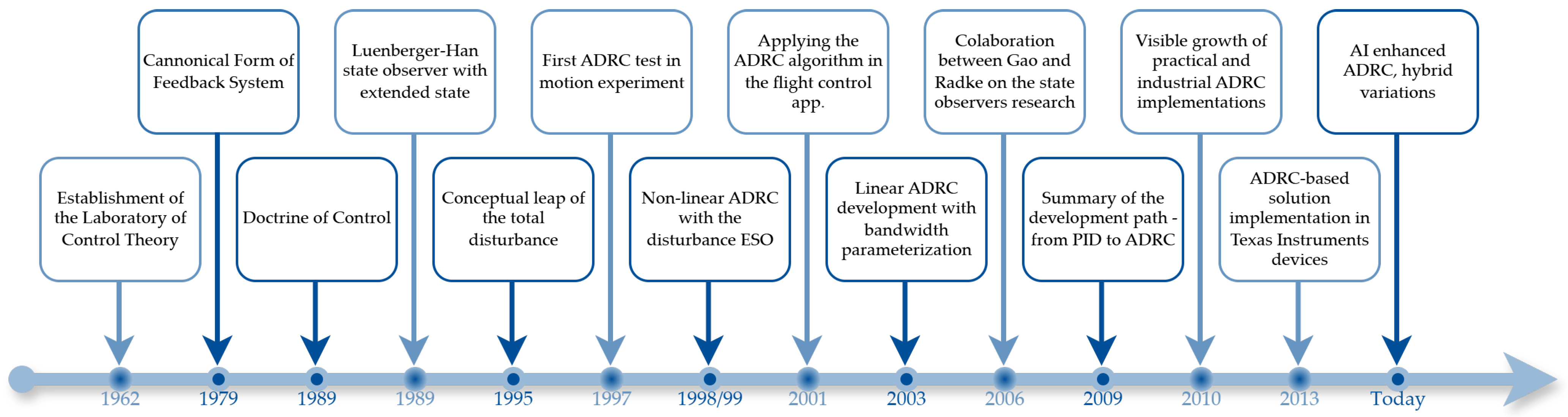
The creation of a controller-focused approach in Control Theory started with prof. Jingqing Han in 1962, when he established the Laboratory of Control Theory at the Institute of Mathematics at the Chinese Academy of Sciences. The work, conducted by prof. Han, leads him to considerations related to the term of the disturbance, which needs to be precisely determined to push the work on the model-free approach forward. Han observes that dividing controlled objects, in general, into smaller, more precisely defined groups is a huge obstacle. By categorizing them into linear, non-linear, stationary, and non-stationary, it is hard to define what a disturbance really is without ambiguity. Han states that all of the mentioned inconveniences can be treated as one, no matter what their nature is, and can be defined as a total disturbance. It should be noted that this is the point where it is said that the total disturbance includes both external and internal disturbances of the controlled process, which is one of the fundamental assumptions of today’s ADRC technique [32]. Having continued his considerations, in 1979, Han showed that the model of the controlled systems can be simplified and reduced to a “Canonical Form of Feedback Systems”. It says that if a proper disturbance definition is assumed, then most of both linear and non-linear plants equipped with state feedback can be simplified to the cascade-integrator concept. As a result, it turns out that it is possible to determine a generalized control law for all of the reduced plant models. That is a crucial breakthrough on the way to obtaining the final ADRC form known today. It is brought up ten years later with a landmark research paper, which for the first time proposes an assumption that in order to carry out a physical control process, a thorough mathematical description of the plant is not necessary [32,33]. The proposed concept is followed by a groundbreaking paper, which was published in 1995 [34]. Han presents a critical discovery. He says that in many processes with some kind of motion, the acceleration can not be fully described with the control signal produced by the controller. It may also consist of an undefined, non-linear, time-varying function. In Control Theory, it may be treated differently, depending on whether it is processed by a non-linear, adaptive, robust control or a system identification issue. Han states that the undefined impact can be treated as a lumped impact of all disturbances (external and internal) and be estimated at once in the form of the extended state. The thorough description of the concept, briefly presented above, is delivered in [31]. The proposed concept of the state observer, consisting of extended disturbance information, is called in the literature a Luenberger–Han observer [31]. The milestones presented are marked on the general timeline shown in Figure 1, which displays the evolution of ADRC.
After several years of conducting initial experiments, Han, in 1998 presented a complete version of the novel control approach. It is called the Active Disturbance Rejection Controller (ADRC). It is considered another breakthrough in the field of Control Theory, as it proposes the entire solution, which is established on the assumption Han had been working on for years. It is a controller-oriented modern control structure, which changes the whole notion of what a control system can be. Its first variation is today known as a non-linear ADRC. It uses a non-linear state feedback and Tracking Differentiator unit, whose main task is to produce the reference signal (and its derivatives). Its main purpose is to increase the ability of the algorithm to follow the reference trajectory and make it physically possible for the system output to follow. However, the non-linear variant of the ADRC algorithm also requires a non-linear Extended State Observer (ESO). That being said, the overall mathematical complexity of the algorithm increases and so does the difficulty of conducting a tuning process. Nevertheless, despite that fact, one of the first applications of the ADRC algorithm is applied as a flight attitude controller, which is another ground-breaking achievement [35]. That was also observed in 2003 by prof. Gao, who proposes a Linear ADRC strategy, which is known today as LADRC [36]. It uses a standard linear State Feedback Controller and Linear Extended State Observer (known as LESO). Furthermore, what is also noteworthy, Gao proposes a bandwidth parameterization approach in the context of ADRC. His paper [36] is considered another significant breakthrough in the field of ADRC strategy. He develops a solution equipped with a simplified controller and state observer. Moreover, both components are parametrized as functions of the controller and state observer bandwidths. The interdependencies of both bandwidths are strictly determined. Thus, at this point, the course of history in the field of Control Theory has been changed completely. The final solution constitutes a universal control framework which does not require the mathematical description of the plant, and its tuning process is reduced to determining a single parameter, which defines the aggressiveness of the control system [31].
At this point, the development and research related to the ADRC technique are rapidly accelerating. There are new collaborations regarding e.g., state observers [37,38], and there is also visible growth in practical and industrial ADRC applications [39,40,41,42,43,44,45,46]. In 2013, Texas Instruments and other companies start replacing the PID controller with ADRC-based solutions in their digital signal processors, which is a mandatory point in the ADRC development path [31,32]. In 2009, all the works related to ADRC development are summarized in another landmark scientific paper, which presents how far ADRC has come from the PID controller to its current form [47].
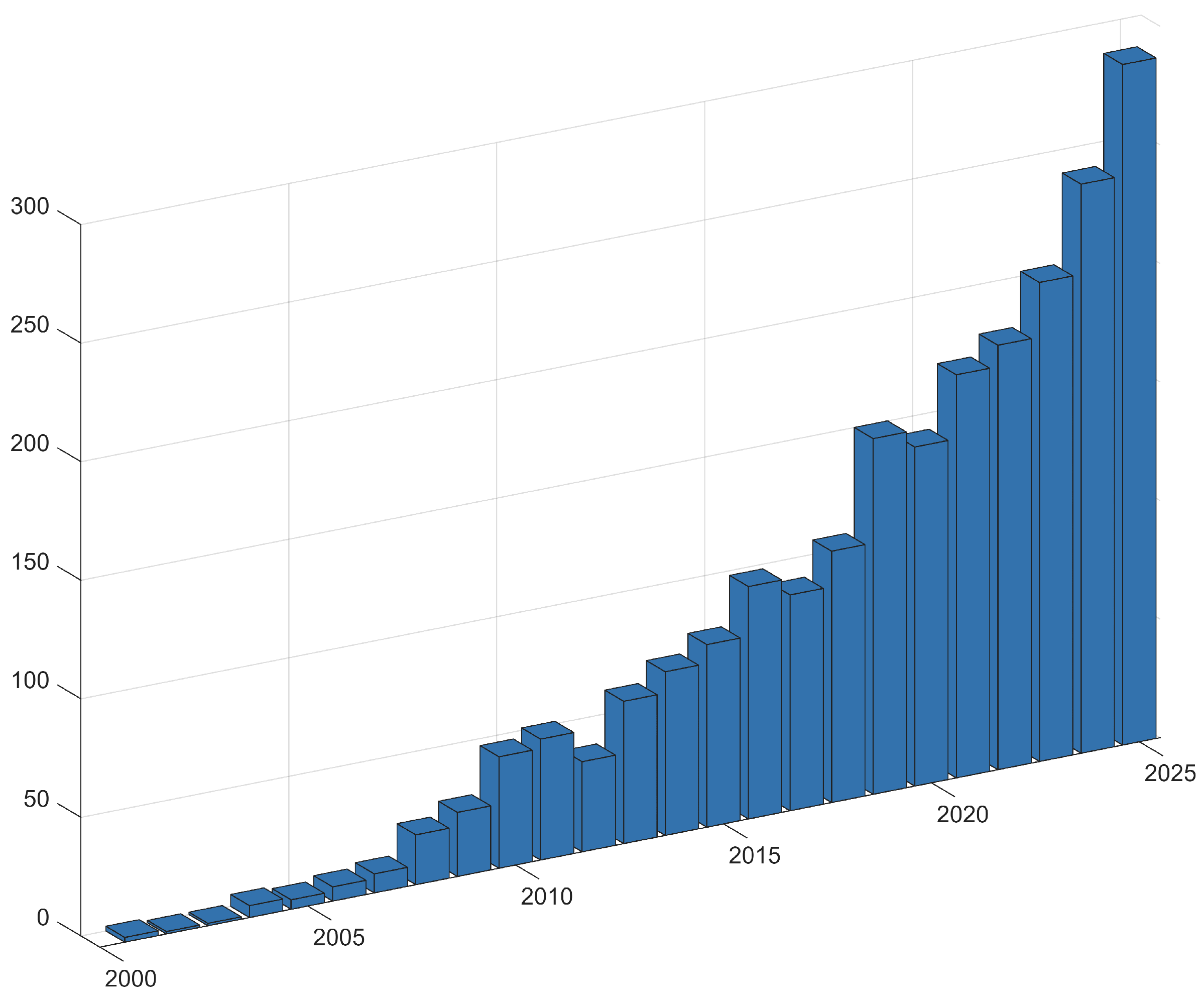
Today, the development of the ADRC strategy has made huge progress. It is known that the Control Theory has gained a completely new and novel design approach. Unlike before, the model-focused design path can be completely inverted. The methodology earned by Han has proven that creating an easy-to-use algorithm, featuring great dynamic properties and robustness combined with a wide range of possible applications, is possible. Imposing a disturbance-free approach to the controlled process is beneficial to the feasibility of the design process. Consequently, the plant can be easily adjusted to the already synthesized controller, which makes it almost immediately ready to operate. Treating all disruptions from both outside and inside the actual plant as a lumped disturbance value redetermines the notion of a modern control system. It shows that every reason for the robust, adaptive, decoupling, and non-linear control to be challenged can now be solved at once [32]. Although the ADRC constitutes enormous progress in the field of control system design perspective, it should be mentioned that it is not flawless. There is still a plant gain coefficient, which creates a bond between the unlimited versatility of the ADRC and actual plant parameters. It needs to be defined during the implementation process, and worse still, its inaccuracy visibly affects the obtained control quality. On the other hand, there are many multilayer and sophisticated plants, which require the use of a non-linear ADRC. This automatically opens up a new blank for incoming improvements of ADRC dynamics, the feasibility of the tuning process, or easiness to implement for both linear and non-linear variants of the control strategy. There is a visible gap in the ADRC excellence that science has been trying to fill since it was created, which will be presented in the further part of the paper. However, this gap is being gradually filled, which is visible in the publication trends, as shown in Figure 2. The interest in the development of the ADRC technique increases from year to year, which only confirms that there is a huge potential in this control strategy, which is yet to be unlocked.

3. Fundamental Principles of the ADRC

3.1. The Core Concept

Active Disturbance Rejection Control is a robust algorithm that is based on the doctrine of control, which is described in Section 2. It provides excellent dynamic properties and feasibility. It also changes the approach of the control system design path. It is based on three main assumptions. The basic idea of the ADRC states that the exact mathematical description of the controlled process is not required, as it can be substituted with a multi-integrator plant interpretation. Thus, all external disturbances are part of a total disturbance, which is estimated online. However, the most crucial part of these assumptions says that all of the modeling uncertainties and internal plant dynamics can be included in the total disturbance value. As a result, the form of the controller can be easily adjusted depending on the order of the controlled process. However, its general structure remains unchanged. To make these statements possible, a more detailed explanation is required. The thorough description of the ADRC theoretical background, which is briefly delivered below, is presented in [48].
The design process of the ADRC algorithm starts with the simplification of the plant, which is needed to include the term of disturbance in it. It can be assumed that the N-th order single-input, single-output object is considered with u as an input and y as an output. Then, the highest derivative (corresponding to the acceleration described in Section 2) of the controlled process output y ( t ) can be described with the control signal and, in some cases, even a non-linear, time-varying function. It is expressed with the following Equation (1):
y ( N ) ( t ) = f ( t ) + b 0 u ( t ) ,
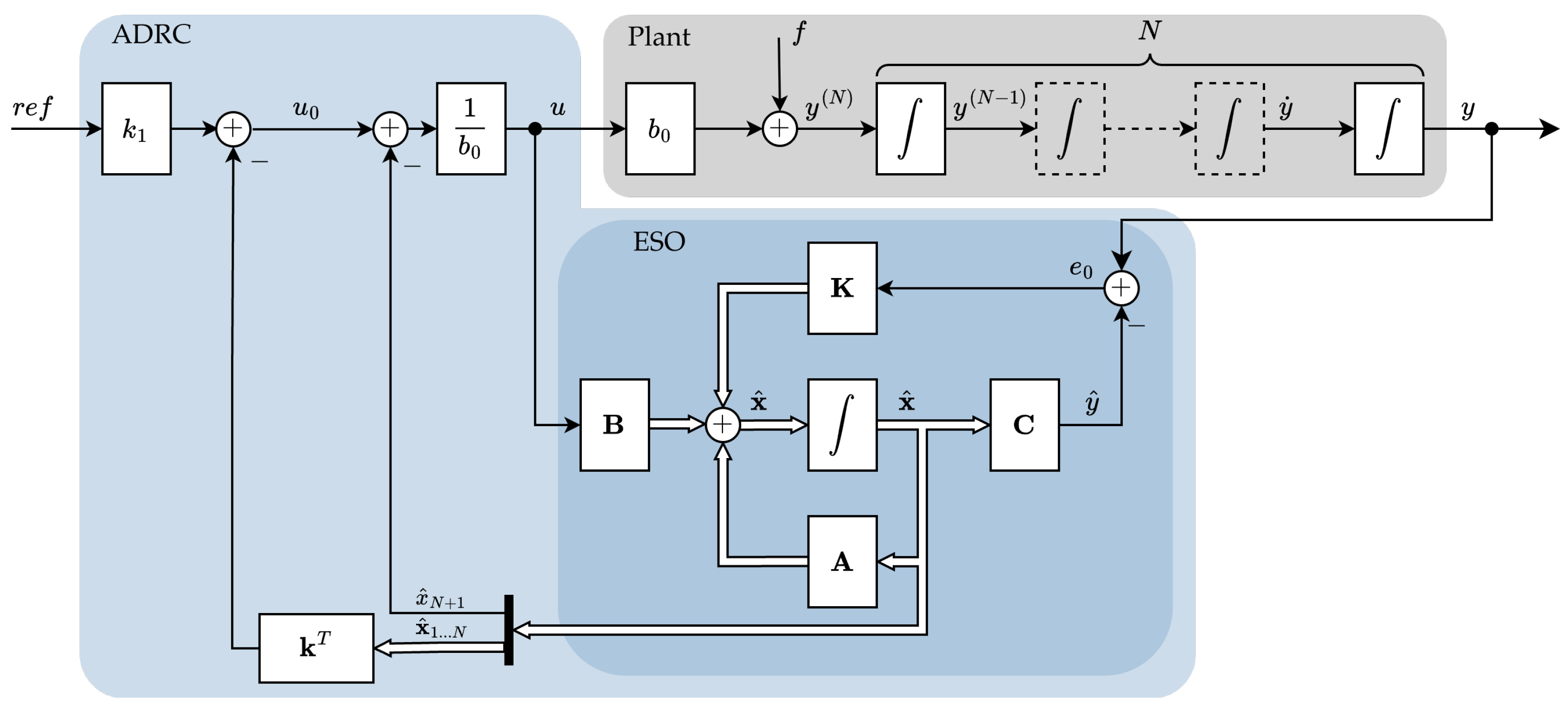
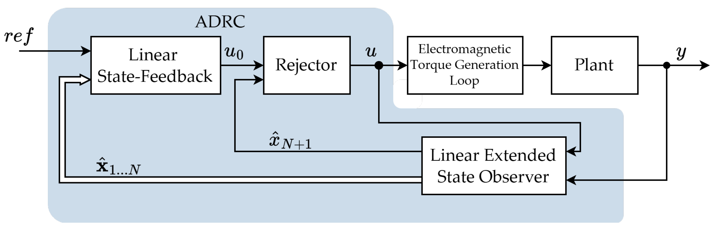
where b 0 is an estimated value of the scaling factor b. It is also called a critical gain parameter, as it directly corresponds to the actual plant parameters (including the estimation error). It is the only parameter in the whole strategy that needs to be known. The f value represents a total disturbance value, which is attached to the controlled plant. It consists of external disturbances that affect the process during operation and the internal plant dynamics with modeling errors. Then, to create a normalized control law, it is required to reduce the plant model to the form of an N-th order cascade integrator structure. To accomplish this, the impact of the disturbance on the plant must be compensated for. Moreover, the influence of the scaling factor b 0 must also be canceled. It is accomplished in the Rejector block. Its internal operation can be presented with Equation (2):
u ( t ) = u 0 ( t ) f ^ ( t ) b 0 .
The normalized plant with the Rejector block operation is presented in Figure 3.
The operation presented above determines what is called an inner loop of the ADRC algorithm. Its main goal is to normalize the plant behavior by compensating the impact of the total disturbance and to invert the plant gain, which is defined by the b coefficient. As a result, the process or the object can be treated as an integrator chain, which simplifies the design of the control law. Thus, taking into account that the control loop is not dependent on the actual plant parameters, from the point of view of the controller, the object is a multi-integrator block. Hence, the controller can be based on the state space vector feedback and a high-order PD controller topology. It uses the control error, defined as the difference between the reference trajectory and actual plant output, and a series of N 1 derivatives included in the state vector y . The control law can be defined with Equation (3):
u 0 ( t ) = k 1 ( r ( t ) y ( t ) ) k y ( t ) ,
where k is a gain matrix of the controller.
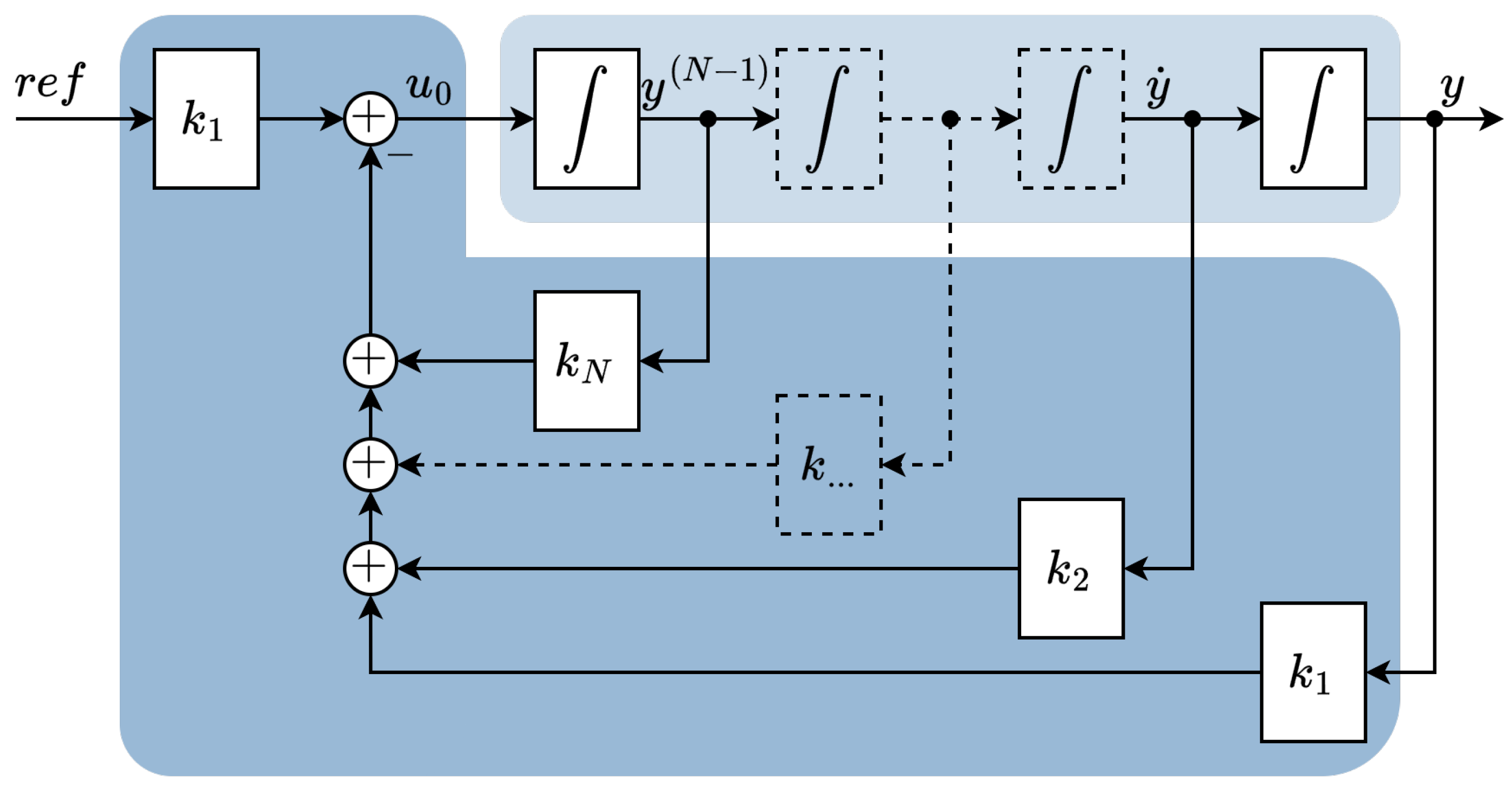
The general diagram of the designed controller is presented in Figure 4. To simplify the overall diagram and general concept of the state feedback controller, the derivatives are taken directly from the plant.
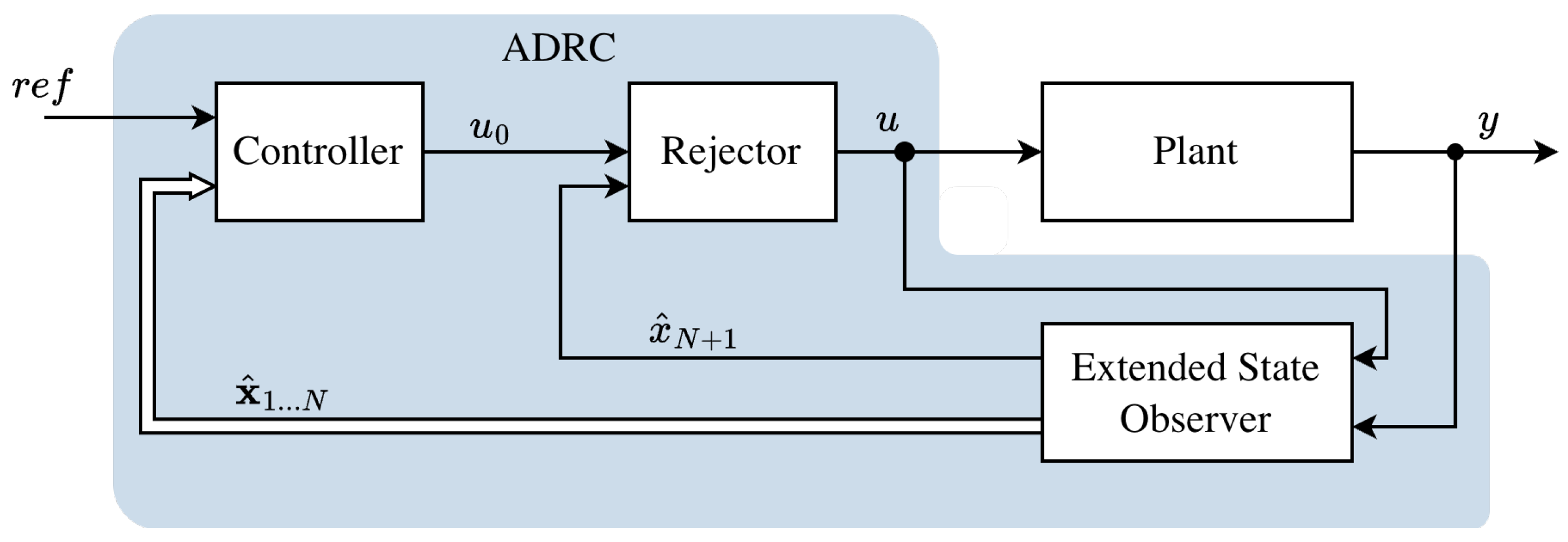
Based on the information provided above, it is concluded that the ADRC topology consists of two control loops, which are shown in Figure 5. The inner loop compensates for the impact of the disturbance and inverts the effect of the plant gain, so the plant can be normalized to the form of a cascade-integrator concept. It is accomplished by using the Rejector block. As a result, a generalized control law can be established. It is achieved by using a state vector feedback controller, which constitutes an outer control loop. Having analyzed Equation (3) and the general diagram of the state-feedback controller, it is known that the desired plant closed-loop dynamics can be defined by the user without the necessity of knowing any parameters related directly to the plant.
Having created the main framework of the ADRC system, it is still crucial to somehow obtain a desired signal, which is essential for the state-space vector feedback. The actual information on the estimated disturbance is required for the inner loop of the control system. In addition, the N 1 plant output derivatives are also needed for the state-feedback controller. All of these signals are acquired by the state observer.
The Extended State Observer is the most crucial component of the whole ADRC structure. It is in charge of delivering all the required real-time information regarding the disturbance and other signals demanded by the controller so that the algorithm framework remains straightforward. It should be mentioned that all of the required feedback information must be obtained by delivering the actual value of the plant output (which can be physically measured) and its input (in the form of the control signal). Considering the normalized plant form of the integrator chain and the need to produce the estimate of the disturbance (including both actual disturbances and modeling uncertainties), it is assumed that the Luenberger-model observer can solve both of the presented challenges. A standard form of the Luenberger state space observer is described with Equation (4):
d d t x ^ ( t ) = A x ^ ( t ) + Bu ( t ) + K [ y ( t ) y ^ ( t ) ] , y ^ ( t ) = C x ^ ( t ) ,
where K is the gain matrix of the state observer.
However, for the purpose of the ADRC algorithm, the default form of the state space vector must be extended with an additional state space variable, which stores the information regarding the estimated disturbance value. As a result, the “virtual input” f ^ ( t ) is omitted. Consequently, the estimated disturbance value plays the role of an integrator state of ADRC, which is mandatory to converge the steady-state error to zero [48]. The closed-loop Luenberger-based state observer with the extended disturbance state space variable is presented with Equations (5) and (6):
d d t x ^ 1 ( t ) x ^ 2 ( t ) x ^ N ( t ) x ^ N + 1 ( t ) = 0 1 0 0 0 0 0 0 0 0 0 0 1 0 0 0 0 0 x ^ 1 ( t ) x ^ 2 ( t ) x ^ N ( t ) x ^ N + 1 ( t ) + 0 0 b 0 0 u ( t ) + K 1 K 2 K N K N + 1 ( y ( t ) y ^ ( t ) ) ,
y ^ ( t ) = 1 0 0 0 x ^ 1 ( t ) x ^ 2 ( t ) x ^ N ( t ) x ^ N + 1 ( t ) .
The Luenberger State Observer is based on an estimation error, which is defined as a difference between the actual and estimated plant output, as shown in Equation (7):
e 0 ( t ) = y ( t ) y ^ ( t ) .
Taking into account the above-mentioned considerations, it is known that the state space vector is extended with one additional state space variable. It stores the estimated value of the combined disturbance. Thus, the estimated vector of state-space variables takes the consecutive form (8):
x ^ ( t ) = x ^ 1 ( t ) x ^ 2 ( t ) x ^ N ( t ) x ^ N + 1 ( t ) = y ^ ( t ) y ^ ˙ ( t ) y ^ ( N ) ( t ) f ^ ( t ) .
The prevalence of the presented approach gives the user the opportunity to shape the dynamics of the state observer, which directly affects the quality of the estimated state space variables. The goal is to achieve a dynamic that allows the estimation error to converge to zero. The general diagram of the ADRC algorithm, including the exact internal structure of the Extended State Observer and the simplified form of the controlled plant, is presented in Figure 6.

3.2. Tuning of ADRC Parameters

In order to provide a satisfying response from the plant, which is controlled with the use of the ADRC algorithm, the parameters of the structure must be adjusted in a specific way. Having analyzed the equations provided in Section 3.1, the estimated value of the plant gain b 0 is a mandatory parameter. Its value significantly affects the way the control signal is scaled to the normalized form of the plant. The inconvenience of the plant gain is the fact that its value directly corresponds to the actual plant parameters, making it the only place in the whole ADRC strategy that is partially dependent on the actual controlled object. It needs to be evaluated during the plant identification and modeling process. Its value does not need to accurately converge to its real-life equivalent b, as it consists of modeling errors. However, there are some cases (presented later), where its significant deviation from the real plant parameters value may visibly deteriorate the quality of the control loop behavior.
After elaborating on the control signal scaling coefficient value b 0 , the gain matrices of the controller k and the state observer K must also be properly adjusted. Considering the linear version of the ADRC technique, prof. Gao proposed a bandwidth-parametrization approach. It is based on a so-called one parameter tuning, which relies on the pole-placement method. As a consequence, there are strict and precisely determined correlations between particular components of each gain matrix. Every single gain also depends on the actual value of the controller ω c or state observer ω o b s cut-off frequency. Sometimes, an additional damping coefficient ξ is also applied to gain another degree of freedom in shaping the final dynamics of the controller or the state observer.
The equation of the outer control loop can be described with Formula (9):
u 0 = k 1 ( r ( t ) y ( t ) ) [ k 2 k N 1 ] · y ˙ ( t ) y ( N 1 ) ( t ) .
Considering that the change in control signal is the N-th derivative of the plant output, Equation (9) can be rewritten in the form of (10):
y N ( t ) k 1 ( r ( t ) y ( t ) ) + [ k 2 k N 1 ] · y ˙ ( t ) y ( N 1 ) ( t ) = 0 .
Thus, determining the final controller gains is accomplished by applying the pole-placement method. After switching the representative polynomial of the controller (10) to the Laplace domain, its coefficients must be compared to the reference polynomial of the N-th order.
The dynamics of the inner ADRC loop is a critical aspect, determining the overall dynamics of the state space vector estimation. It is crucial to provide an accurate estimation of the extended disturbance variable, which directly impacts the quality of the closed-loop control response. The particular components of the state observer gain matrix are also selected using the pole-placement method. The theory of modal control assumes that the state observer can be considered a closed-loop system. Hence, its characteristic polynomial equation is defined with the following expression (11):
m ( p ) = det ( p I ( A KC ) ) ,
where p is the Laplace domain operator. Then, the obtained coefficients are compared with the specific expression obtained by comparing the state observer characteristic polynomial to the reference polynomial of the N + 1 -th order. The most crucial aspect lies in the interactions between the controller and the state observer bandwidth. It turns out that these values can not be independently selected, as the inner disturbance estimation loop must be significantly quicker than the outer control loop. Thus, the cut-off frequency of the state observer should exceed the corresponding parameter of the controller between 3 and 10 times.

4. Control Strategies Based on Rejection Control

4.1. Modifications of ADRC

The algorithm presented in Section 3.1 is a linear variant of the ADRC technique, which was first presented and introduced by Gao in 2003 [36]. Despite providing excellent properties, it needs to be emphasized that it does not qualify for every kind of controlled process. Sometimes, a more sophisticated tool is required, especially in the case of a high-order, non-linear system. The ADRC, however, is by definition a versatile control strategy. Hence, it is known that there are many different analytical modifications that are included in the ADRC family. All of them are thoroughly described by prof. Madoński and prof. Herbst in [48].
The first modification of the linear ADRC algorithm proposed in [48] focuses on adding additional model information. The presented approach may lead to improving the performance of the algorithm if the user stores some information about the controlled process from, e.g., previously conducted identification, experiments, or documentation. At this point, two approaches are distinguished. Additional information about the model can be included in the state observer, but it can also be incorporated into the plant description. Extending the state observer with additional information about the occurring (e.g., periodic) disturbance may increase the estimation performance and the quality of the acquired state space variable estimates. However, it results in more than one extended state space variable, which requires adjusting the additional gain coefficient. On the other hand, it is possible to extend the system matrix A with additional model information. Nonetheless, the second approach leads to the modified form of the controller, which may require a redefinition of the control law and controller gains. However, the authors of the book [48] emphasize the fact that the presented approach should be considered if the effort is worth the additional performance gained with the described method, which needs to be assessed for a particular control case.
The second modification includes an altered form of the reference trajectory generator. In a standard approach, a constant value of the controlled state space variable is set. Then, the state-feedback approach is employed to converge the control error to zero. The control error is, though, defined as the difference between the reference point and the process output. However, considering motion applications, it sometimes may be crucial to impose additional constraints on the estimated derivatives, so, e.g., acceleration or even jerk can be controlled. The tracking performance of the ADRC-controlled plant can be visibly improved if the reference signal is equipped with additional N derivatives of the reference signal r ( t ) . However, the described modification also requires the adjustment of the control law, which is presented in detail in [48]. The described solution works very well with the time-varying reference signal trajectory.
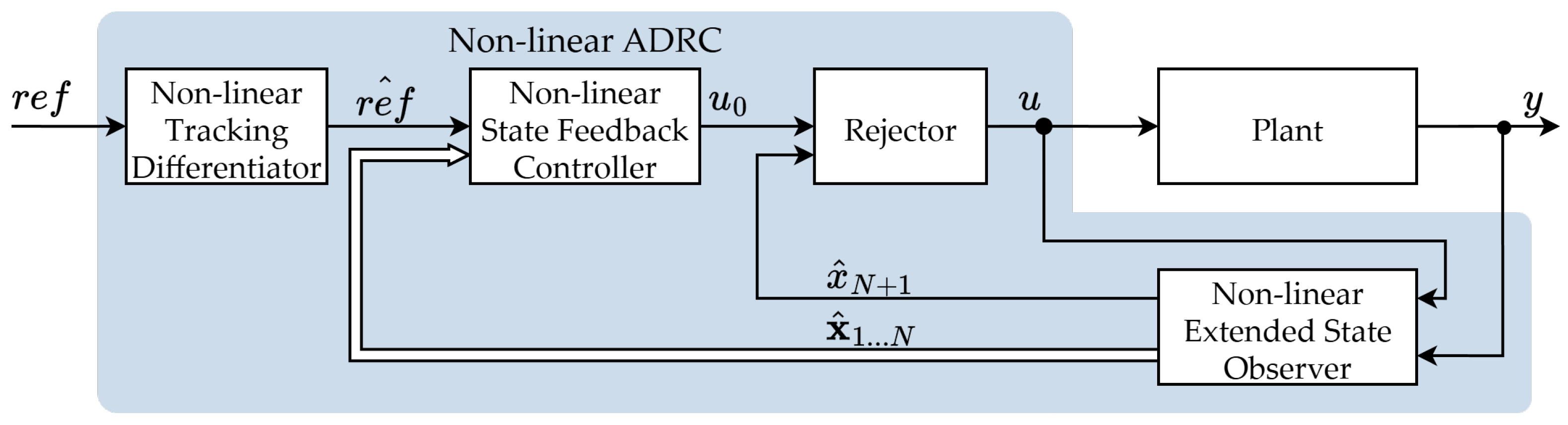
The original variant of the ADRC algorithm, designed and developed by Han [47], is by default a non-linear form. It is marked by the fact that the reference trajectory generator is substituted with a so-called Tracking Differentiator (TD) unit. It is in charge of estimating high-order derivatives of the control signal trajectory. However, unlike the previous ADRC variation, this form of the strategy uses a non-linear weighting function, which impacts the signals in the state-feedback controller and the state observer. The numerical complexity of the described ADRC variant is considerably higher than that described previously. However, the non-linear components of the structure can provide significantly increased performance, especially when it comes to accurate reference signal tracking of high-order systems. The role of the Tracking Differentiator can be used in several ways. First, it can play the role of the reference trajectory generator, which improves the output response when the reference signal derivatives are only known in particular time. Alternatively, a TD block can be applied as a Transient Profile Generator to provide a smooth trajectory of the reference signal and its derivative transients. It is especially essential in the case of, e.g., servo or motion systems with a sophisticated mechanical structure of the drive. The detailed analysis of the briefly presented scenarios is included in [48]. The general diagram of the non-linear variant of the ADRC algorithm is presented in Figure 7.
Another interesting modification of the ADRC strategy, which is also widely tested, is an error-based ADRC. The whole strategy assumes that the derivatives of the reference signals are not available. The actual estimate of the total disturbance value is obtained by deriving the control error signal. The mentioned control error is delivered to the observer as an input. Then, the control law form can be transformed into the transfer function, which simplifies the controller form. Based on that, the modified control law is also redefined. The described ADRC form is suitable for applications that require accurate trajectory tracking capabilities [48,49,50].
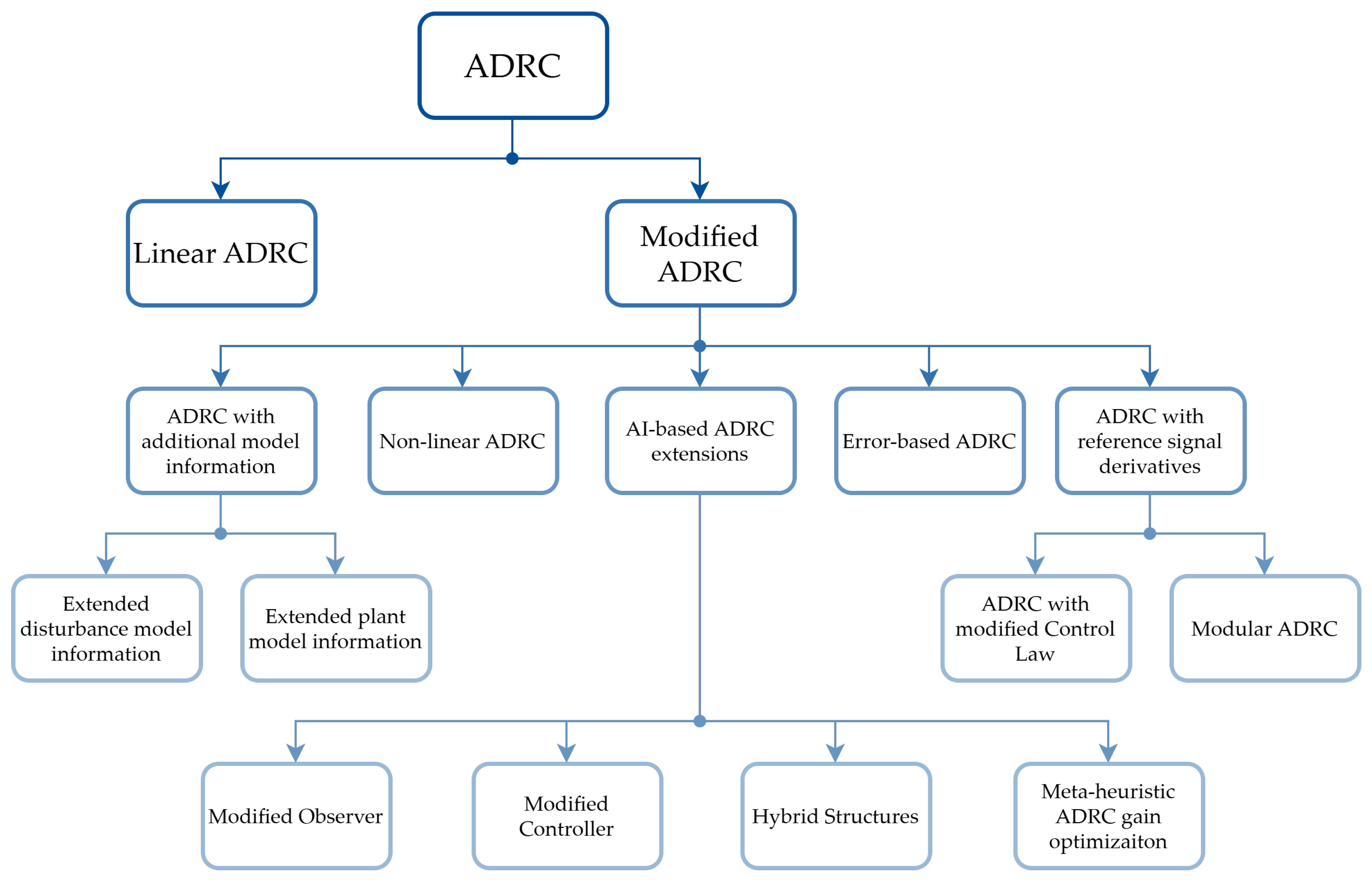
Having combined all of the above-mentioned ADRC variants, summarized in Figure 8, it is concluded that all of the requirements regarding modern control system definitions are fulfilled by the ADR controller.
It is simple to implement and deploy in a real-life scenario, has a wide variety of potential applications, and provides excellent dynamic performance. Moreover, it is a robust control algorithm, which delivers eligible plant response even if the plant or process parameters are not accurately determined. However, there are also many operating conditions and specific industrial applications in which modifying the linear ADRC is not a favorable solution, as it may consume too much numerical resources or the tuning process may seem infeasible. A standard ADRC variation also has some drawbacks. First of all, it is a robust algorithm, which means that it provides a satisfying plant response in a limited, predefined range. Sometimes, especially considering motion and electric drive applications, the parameters of a non-stationary object may vary in time to a larger extent than assumed earlier. Despite the fact that the control approach during the design process is generally correct, it requires additional adaptation capabilities to extend its robustness and response eligibility. Secondly, it may sometimes turn out that the accuracy of the plant gain assessment is not sufficient, as it consists of several hard to identify components [51,52]. Then, the additional adaptation law can be useful, as compensation for plant uncertainty can be achieved during control system operation without the necessity of conducting an additional identification process. What is also crucial is the fact that sometimes, the non-linear variant of the ADRC may be essential. Then, an additional algorithm to simplify the complexity of the tuning process may also be required. In all of the proposed scenarios, the ADRC algorithm needs some kind of extension that would fill the specific requirement gap. To accomplish this, attempting to use artificial intelligence tools can be expected to bear positive results. Hence, the authors consent to extend the overall ADRC variants division and add another group, which is called AI-based ADRC extensions.

4.2. Solutions Based on ADRC Applied for Electric Drives

Considering the increasing number of published articles with an emphasis on the ADRC algorithm shown in Figure 2, it is known that the control strategy has found its way to various industrial applications. It has been intensively tested in many fields. Moreover, the number of modifications applied specifically to tackle particular problems with regard to the ADRC technique is increasing as well. A small modification of the combination of known techniques with ADRC may lead to astonishing results, which may solve an awkward control problem.
The ADRC algorithm is also widely implemented in the field of electric drives. Modern drive systems are expected to provide excellent dynamic performance combined with high reliability. That is often possible due to the presence of permanent magnet motors in today’s electric drive automation. The most common choice in dynamically demanding electric drive applications is a vector control technique (e.g., Field-Oriented Control (FOC) or Direct Torque Control (DTC) strategy). However, despite giving the user the ability to control the electromagnetic torque during dynamic states of the drive, it can sometimes be tough to implement, as it requires tuning several PI controllers, which may not always provide additional robustness to time-varying drive parameters. Nonetheless, some studies prove that substitution of the PI controller in the outer speed regulation loop with the ADRC technique may be a novel and satisfying approach in the field of AC motor control. The general idea of the torque control remains unchanged. Then, the outer speed controller is implemented in the form of the ADRC strategy, which visibly increases the quality of the speed control loop response. The reaction of the system to the occurred disturbance can be easily improved [53,54]. What is more, after performing additional modifications of the ADRC technique, it is possible to handle high-order time-varying disturbances [55], including periodic and aperiodic disruptions of the Permanent Magnet Synchronous Motor (PMSM) [56]. It can also be easily adopted to the issue of efficient position control of sophisticated and complex mechanical systems [57].
On the other hand, considering electric drive applications, the desire to deliver high dynamics to the controlled plant is not the only problem. Time-varying internal parameters or external disturbances may cause significant and visible deterioration of the plant response. Moreover, there is a string of different phenomena that may lead to unfavorable drive behavior (e.g., speed fluctuations). Thus, it turns out that after a minor modification of its structure, using the ADRC technique may visibly mitigate inconvenient scenarios. For example, having combined the ADR controller with the phase-locked loop observer, not only can excellent dynamics of the PMSM motor be achieved, but increased robustness to variation of plant parameters may be easily provided as well [58]. Using a PMSM motor is also expected to deliver smooth speed regulation. However, sometimes due to some internal disruptions of the drive, the motor speed starts to fluctuate aperiodically. To address this problem, the ADRC technique can also be applied. Combining a standard ADRC method with a proportional-resonant controller allows effectively suppressing those fluctuations. Meanwhile, the general simplicity of the ADRC algorithm remains unaffected [59]. In addition, there are also specific scenarios where an accurately modeled and identified plant is not always easily accessible. Then, the ADRC provides robustness against small parameter uncertainty. However, there are some studies providing that by using a slightly modified form of the disturbance observer (fully decoupled ADRC), it is still possible to deliver a good tracking performance combined with efficient disturbance rejection capabilities. The results described in [60] also ensure that the proposed solution provides robustness against imperfectly modeled inertia of the plant. Considering PMSM drive systems, the ADRC technique can also constitute a fundamental component of more complex control systems. For example, after using the ADRC outer speed controller alongside model predictive current control with an additional inductance observer, the capabilities to suppress external and internal disruptions of the system can be increased [61]. The described system can effectively suppress external disruptions in the speed control loop and eliminate the impact of the inductance parameter mismatch. All of the extensions of the ADRC algorithm presented above are meant to improve the ADRC robustness to a variety of unfavorable circumstances and make the ADRC algorithm a feasible choice even for the most demanding real-life applications.
One of the most rigorous applications of the electric drive system is an electric vehicle (especially an electric car). The applied control strategy needs to be resilient to different operating conditions, external environments, and internal parameter variations, depending on the load carried by the car. To handle all of these requirements, ADRC is often applied in the PMS motor control system placed in the propulsion of electric vehicles [45,62]. It is a perfect solution, providing high performance speed response and robustness, even for more advanced PMSM variants [63]. As stated previously, there are also scientific works related to the improvement of dynamic performance achieved with the use of ADRC [64]. It can be, e.g., extended with Fuzzy Logic to conduct a self-adjustment process of the linear ADRC to improve the speed control accuracy [65]. However, in the case of such a sophisticated object, such as an electric car, there are also more complex improvements of the ADRC strategy. For example, in the research described in [66], the authors propose a combination of the two most popular variants of the ADRC technique to derive advantages from each structure at once. The elaborated solution is called an Adaptive Hybrid ADRC strategy. It is designed to handle the problem of PMSM speed control in the electric vehicle drive train. The authors created a hybrid connection of linear and non-linear ADRC forms, which are coupled together with a weighting mechanism. The goal is to obtain a smooth transition between particular control signals, which are generated by each ADRC variant. The purpose of using two ADRCs is to provide better suppressing capabilities of uncertain non-periodic and periodic disruptions. However, what is even more interesting is that in this particular case, the authors also applied an Adaptive Resonant Controller to quickly detect and suppress periodic disturbances with uncertain frequencies. The proposed control strategy, although more sophisticated than a standard LADRC, features a visibly improved resilience of the propulsion to unknown disturbances of different types.
In the field of vehicles, the issue of motor control is not the only case in which the ADRC technique is applied. Considering a speed tracking cruise control solution, ADRC can be a viable approach. In a presented application [67], it controls the speed tracking of the electric motor of a two-wheeled electric vehicle. It is applied as an outer speed controller in the Field-Oriented Control Strategy. As a result, great dynamic performance is combined with ADRC feasibility and robustness, which is a perfect solution for an electric vehicle. However, in modern automation, there are also more complex multi-level control solutions, which can be found in cars in general. One of the great examples of such structures is an Adaptive Cruise Control System. According to the solution proposed in [68], the whole control system consists of two controllers. The first one, the upper level controller, calculates the optimal acceleration value, which is dependent on the actual speed and the speed reference. Then, the ADRC is employed in the form of a lower controller. Its main task is to ensure the tracking of the desired acceleration provided by the first controller. The whole difficulty relies on the necessity of compensating the non-linear dynamics of the vehicle simultaneously. By applying the ADRC technique, it is again possible to provide good dynamics of the system and to ensure that all of the parameter uncertainties and unknown disturbances are suppressed. The proposed solution is a perfect tool, considering the time-varying nature of the car as a plant, including different load values and hypothetical road slopes, which are additional external disruptions.
Having analyzed the real-life applications presented above, it can be noticed that every single example presents a more and more sophisticated process within which the ADRC operates. Industrial applications and processes usually consist of different machinery with multilayer control problems and complex mechanical structures. Wind turbines are another example of a sophisticated machine, where several electric drive units can be distinguished. The wealth of state space variables that need to be controlled requires an impeccable approach to the control system design process. One of the most crucial drive trains that the wind turbine is equipped with is a pitch system. The angle of the pitches attached to the rotor impacts not only the rotor speed but also the total output power and the efficiency of the power conversion process. However, what is even more important is that the pitch positioning system is also responsible for protecting the turbine from damage in case of high wind. It turns out that the above-mentioned tasks can be accomplished effectively using the ADRC technique [69]. What is even more important is that considering such a complex object as the pitch positioning system, the LADRC technique delivers better dynamic performance than the PD and Fuzzy Logic PI controllers used in similar conditions. What is also noteworthy is the fact that this dynamic is achieved while still delivering the feasibility and easiness of the tuning process, which the ADRC is known for [70].
On the other hand, the concern of output power control in the case of a wind turbine is another issue, where the ADRC strategy can be implemented. It is tested in wind turbine applications as a control strategy, which is to guarantee, e.g., an effective damping of power system oscillations [71]. The external environment in which the wind turbine operates is highly unfavorable and unpredictable. Thus, it is a common concern that time-varying conditions may cause frequency oscillation in a power grid. Hence, the ADRC technique is also implemented to reduce frequency oscillations [72]. However, the described phenomenon is particularly dangerous in the case of offshore, floating wind turbines. In that case, the uncertainty of the controlled process and the magnitude of external disturbances in the form of wind and waves constitutes a serious impact on the stability of the power output. It turns out that ADRC can guarantee the stability of the power output while avoiding increasing the platform load by controlling turbine power [73]. The ADRC, however, can also be applied to control the whole wind energy conversion system. The solution presented in [74] is based on a Permanent Magnet Synchronous Generator (PMSG). In this particular application, the wind power and energy efficiency are maximized with the utilization of the ADRC technique, which enforces the reference torque that the PMSG is to maintain. The Active Disturbance Rejection (ADR) strategy is also an excellent choice when it comes to controlling more complex turbines, i.e., a dual-rotor wind power system. By implementing the ADR strategy to mitigate the impact of changes in wind speed, fluctuations in power output can be significantly reduced. In addition, system stability and overall efficiency can be improved [75]. It is worth noting that the impact of the ADRC can also be extended to controlling and synchronizing the power systems. The operation of the wind turbine is not limited to the drive system inside it. For example, the dynamic performance of the DC bus voltage is also crucial, as it can be affected by disturbances from both the wind turbine and the grid itself [76]. Furthermore, the issue of integrating power systems and the offshore power grid is also a huge concern that needs to be controlled [77]. The ADRC algorithm can also be employed to handle the mentioned scenarios.
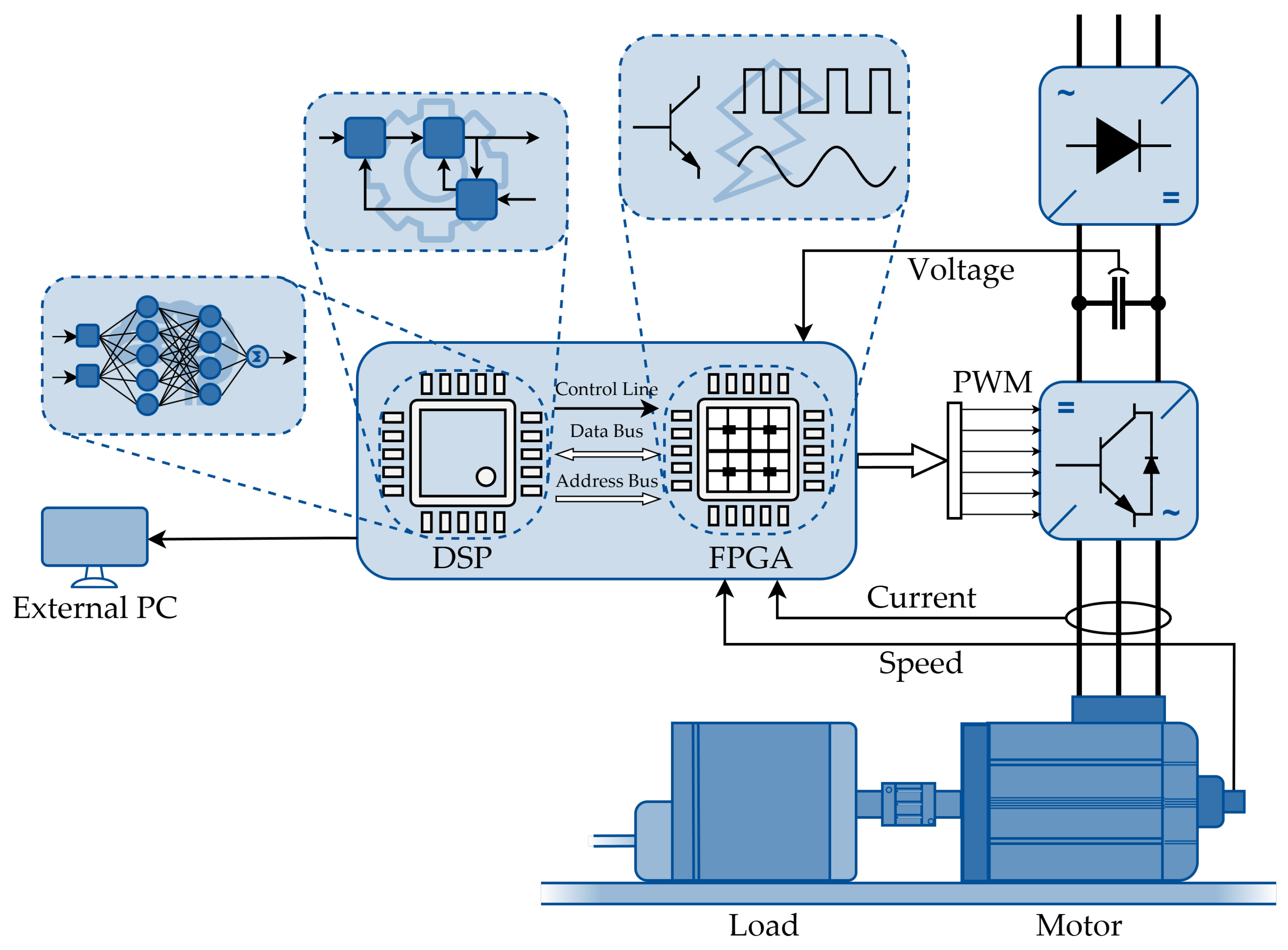
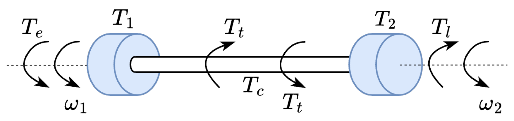
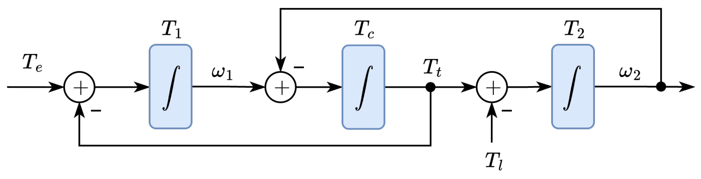
The issue of controlling wind turbines or electric cars is a tough task. Considering the mechanical part of the wind turbine or the electric car propulsion, it can be concluded that it is sophisticated and complex machinery. That is because the electric motor or generator must be coupled with a specific kind of external device, which needs to accomplish a specific task it was designed for. Then, it is known that the whole device needs to be taken into account during the control system design process. However, the amount of different components of these devices makes their parametrization, identification, and control a huge concern. Hence, the modern automation distinguishes a separated branch of control systems, which are dedicated specifically to control so-called two-mass drive systems. The term “two-mass system” is defined as the connection of two rotational machines (an electric motor with an external load machine) with the use of a shaft as a third rotating mass between them. A wind turbine is a great example of an electric drive with a sophisticated mechanical structure [49]. For the sake of scientific research, however, the purpose of using that shaft is not only to transfer the electromagnetic torque from one machine to another but also to introduce torsional torque and impose the presence of torsional vibrations. As a result, it is possible to recreate the worst potential operating scenario on the laboratory stand. The problem of two-mass systems control is a difficult issue from the point of view of Control Theory. In order to provide a satisfying plant response quality, an accurate identification of two-mass drive parameters is demanded. That often forces the need to use a complicated measurement system, as a typical two-mass control approach requires full state-space vector feedback. Standard two-mass control solutions are also not resistant to time-varying plant parameters, modeling uncertainties, and the non-stationary nature of the complex two-mass object. Yet, the ADRC strategy is an excellent solution in two-mass systems control as well. Not only does it perform excellent dynamics, but it also uses only one physically measured feedback, which is an uncommon solution in the field of two-mass drives [78,79]. The ADRC algorithm is implemented to compensate the backlash, which occurs in the connection between two machines [80,81] and causes a significant delay between the motor speed change and the actual load machine response. That delay is an undesired phenomenon, which visibly hinders the issue of accurate speed or position control in the case of two-mass drives [82]. Another reason why ADRC is a promising solution in two-mass systems control is its capability to compensate the presence of torsional vibrations [83,84]. Their presence may lead to fatal consequences in long-term drive operation, e.g., damage of the shaft or clutch.
Complex mechanical couplings are an inseparable part of robots of all kinds, especially considering manipulator robotic arms. Electric motors are attached to the further part of robotic joints, which are exposed to external forces, disruptions, and the impact of torsional torque. That being said, a proper electric drive control system in case of robotic applications also requires a decent approach, providing high accuracy of the accomplished movement and resistance against time-varying parameters of the controlled process. As prof. Madoński stated in his PhD thesis, in the case of robotic applications, a modeling and parametrization of the plant may be a tedious task. That is the reason why minimum-model approaches are willingly chosen. However, the simplicity of the deployment process is obtained at the price of lower precision, which is also not a favorable scenario [85]. The electric drive unit of the robotic arm in modern automation is usually accomplished in the form of a high-precision servo system. The role of the servo drive is nowadays performed by the PMSM motor, as it provides high speed combined with the possibility of high-precision control. It perfectly fits the needs of a robotic application. Having combined the PMS motor with the ADRC strategy, it is possible to achieve high performance and accuracy in the task of following a particular trajectory. Despite the fact that using the ADRC technique is a common choice in robotic application, it is still being improved by the research and scientific community. One of the examples is a load adaptive two-loop drive system based on the ADR controller with a fuzzy self-tuning method. The proposed solution features high speed and positioning accuracy integrated with the ability to adapt to load changes [86]. Robotic control systems with Active Disturbance Rejection are also applied to achieve precise trajectory tracking, as recreating a reference position trajectory is one of the most mandatory robotic tasks that a modern automation must accomplish. The state of the art shows that in case of robotic applications with several modeling uncertainties, the ADRC algorithm is a modern answer to the problem of accurate position control while providing the desired performance level and displacement deviation at the same time [87,88,89,90]. Furthermore, the ADRC is also an eligible choice when it comes to controlling the manipulator with two degrees of freedom with the assumption that the mathematical model of the controlled object is only partially known. As a matter of fact, the controlled device is a multi-input, multi-output system, which enforced the employment of two ADRC controllers. It has been proven that despite significant plant uncertainties, the control system managed to provide satisfactory dynamics. However, what must be emphasized at this point is the fact that the control system based on the ADR strategy obtained better results than the PID controllers in various external conditions and better robustness to time-varying plant parameters [91].
All of the ADRC applications presented above focus mainly on the purpose of an electric drive. However, to emphasize the versatility of the disturbance rejection approach, it must be mentioned that it is a satisfactory technique for many different devices as well. It can be applied as a path-planning controller for autonomous vehicles [92], for self-driving race cars [93], and for unmanned vehicles [94]. In the field of vehicles, it can be also implemented as a various auxiliary control system, e.g., to control the pose of an electric coaxial two-wheeled electric scooter [95], to control the traction control system of an electric car [96], to control a group of autonomous vehicles in zero trust environments as a paramount controller [97], and to handle an electronic differential system of a four-wheel drive electric vehicle [98]. A wide range of possible ADRC applications is also highlighted by the fact that it can also be implemented as an autopilot for tracking a ship course [99,100]. The described application is again vulnerable to highly non-linear disruptions (wind, waves, stream), which are extremely hard to describe mathematically. What is even more difficult is the unpredictable nature of these disturbances. The ADRC technique can also be an answer to aircraft autopilot pitch [101] or attitude control [102]. Moreover, it has the potential to be applied as a controller to unmanned flying vehicles, on-board manipulator arms, or radar as a high-accuracy positioning system [103,104,105,106] or in more sophisticated processes to suppress harmonic uncertainties of different kinds [107,108]. The variety of different applications also includes mobile robots [109].
The analysis of the presented examples of real-life ADRC applications shows both its standard and modified forms. Depending on the particular purpose, the algorithms presented above include modified control law equations, a modified state observer, or even combining several ADRC approaches to create a hybrid structure. No matter what kind of modification is applied in particular cases, it is clearly visible that current research and scientific trends aim to make the ADRC an even more robust and versatile algorithm. There is a visible trend to maintain the easiness and feasibility of the ADR approach while increasing its resilience to time-varying and non-linear phenomena and objects. However, sometimes, the required modification enforces the need to switch to a non-linear variant of the ADRC strategy. Considering a wide gamut of modern AI tools, it is worth considering using such solutions to enhance the capabilities of the ADRC algorithm. As a result, the ADRC algorithm may be equipped with an additional adaptation mechanism, and its robustness can be visibly expanded with low numerical complexity.

4.3. Neural Modifications of Active Disturbance Rejection Controller

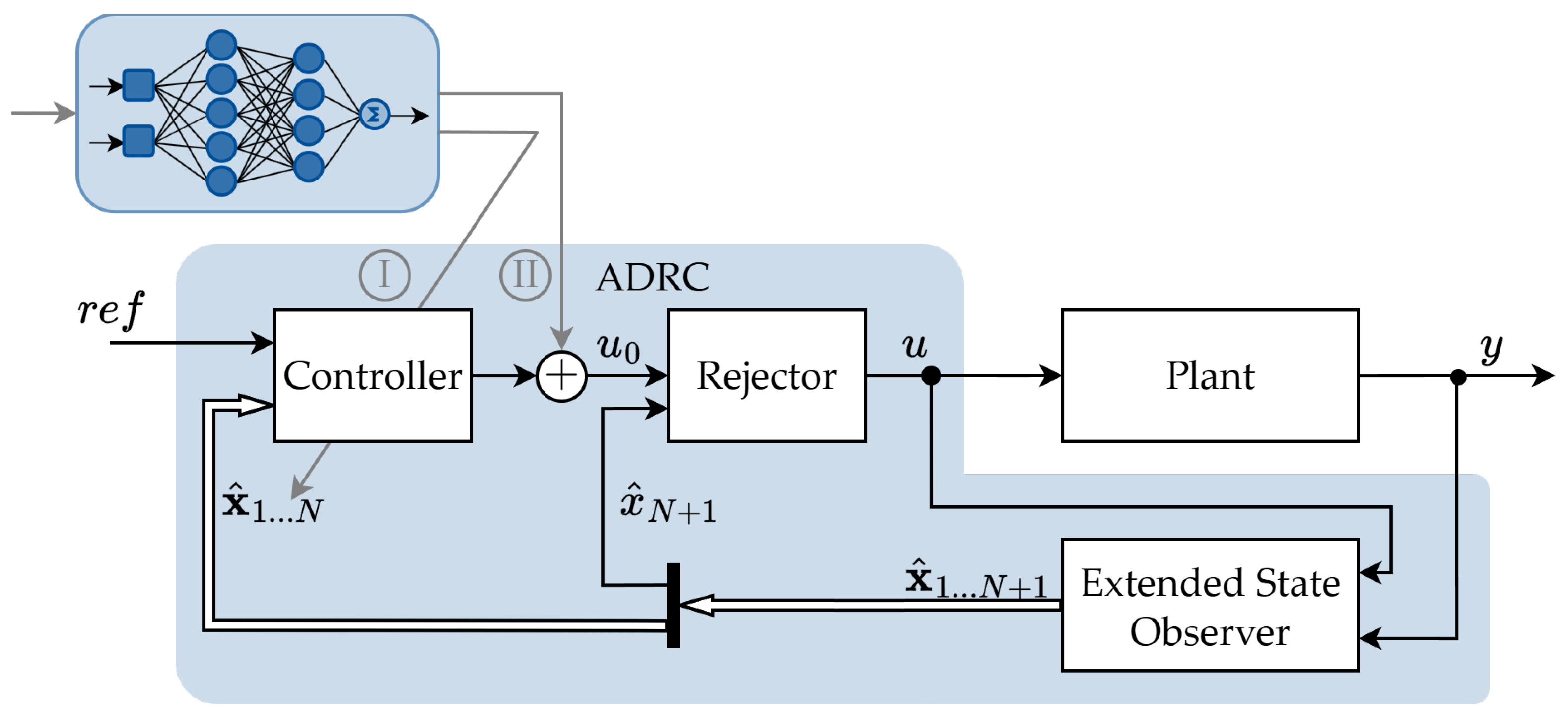
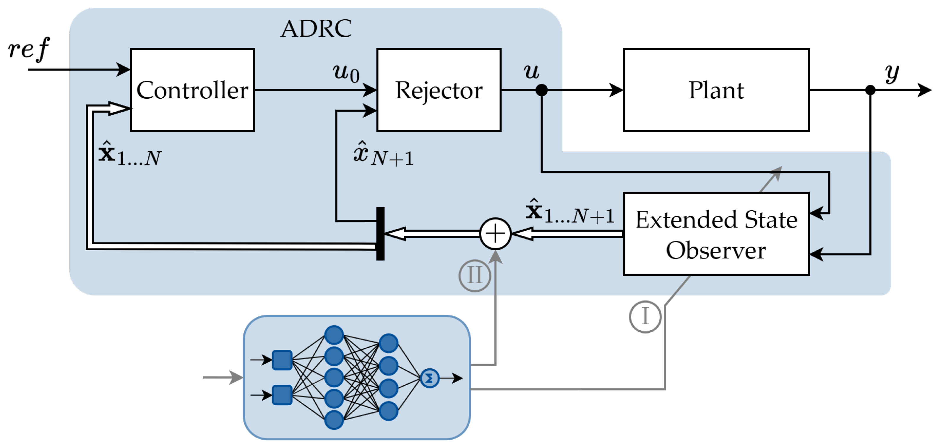
In case of neural modifications of the ADRC algorithm, the outer control loop extensions should be considered. In a standard approach, the paramount loop is equipped with a state-feedback controller, which is possible due to the ADRC assumptions described earlier. As mentioned in Section 3.1, by converting the plant model to the form of a cascade-integrator model, it is possible to obtain a universal control law that is based on a state-feedback approach and a PD controller as its core. However, in the described case, there is a necessity of performing a gain matrix component adjustment to provide the desired dynamics of the outer control loop. In a classical approach, it is accomplished with the use of a pole-placement method and a bandwidth parameterization method. It uses a predefined correlation between particular controller gains and controller cut-off frequency. However, by applying this strategy, the dynamics of the paramount loop are fixed and determined during the design process. If any plant uncertainty exists, it is possible that the obtained control loop dynamics does not meet the desired dynamics criteria. Hence, one of the most popular ADRC modifications, which is widely implemented in the paramount loop, is a neural adaptation of the controller gain coefficients [110,111]. The proposed strategy gives the control system designer the possibility to shape the outer loop dynamics regardless of the dynamics of the state observer. As a result, the accuracy of the recreated state space vector components, including the estimated total disturbance value, remains unbothered. What is also important is that the proposed solution can also be found in many different applications—not only in the field of electric drives. For example, in some scenarios, a separate adaptation of each controller gain may not be favorable. Instead, the overall controller dynamics can be changed by modifying its cut-off frequency in general [112]. In case of unknown plant parameters, modeling errors, and internal uncertainties, the deviation between the actual and estimated plant characteristics may seem significant. In that scenario, applying a neural adaptation mechanism improves the controller reaction during dynamic states of the drive and increases the accuracy with which the system follows the trajectory of the reference state space variable. What is also crucial is that there is a possibility to change the internal structure of the controller itself by substituting the state-feedback approach with a neural network [113]. If the controlled process can be described with a low order model, it may be feasible to replace the PD controller with, e.g., a Radial Basis Function Neural Network (RBFNN), which reduces the necessity of conducting a controller tuning process completely and delivers the adaptation capabilities of the outer control loop. In some cases, particularly in the field of electric drives, sometimes there is a need to increase the controller dynamics only for a while, e.g., during dynamic states of the drive. Then, the neural network can be applied to the controller as well. The purpose of the proposed extension is to increase the controller bandwidth based on the actual system torque demand. As a result, the controller dynamics remains its default level during steady states. The overall robustness of the control system to time-varying parameters and the non-stationary nature of the object is significantly increased. However, the issue of the stability of the proposed solution must be considered, as the controller dynamics cannot be increased with no control.
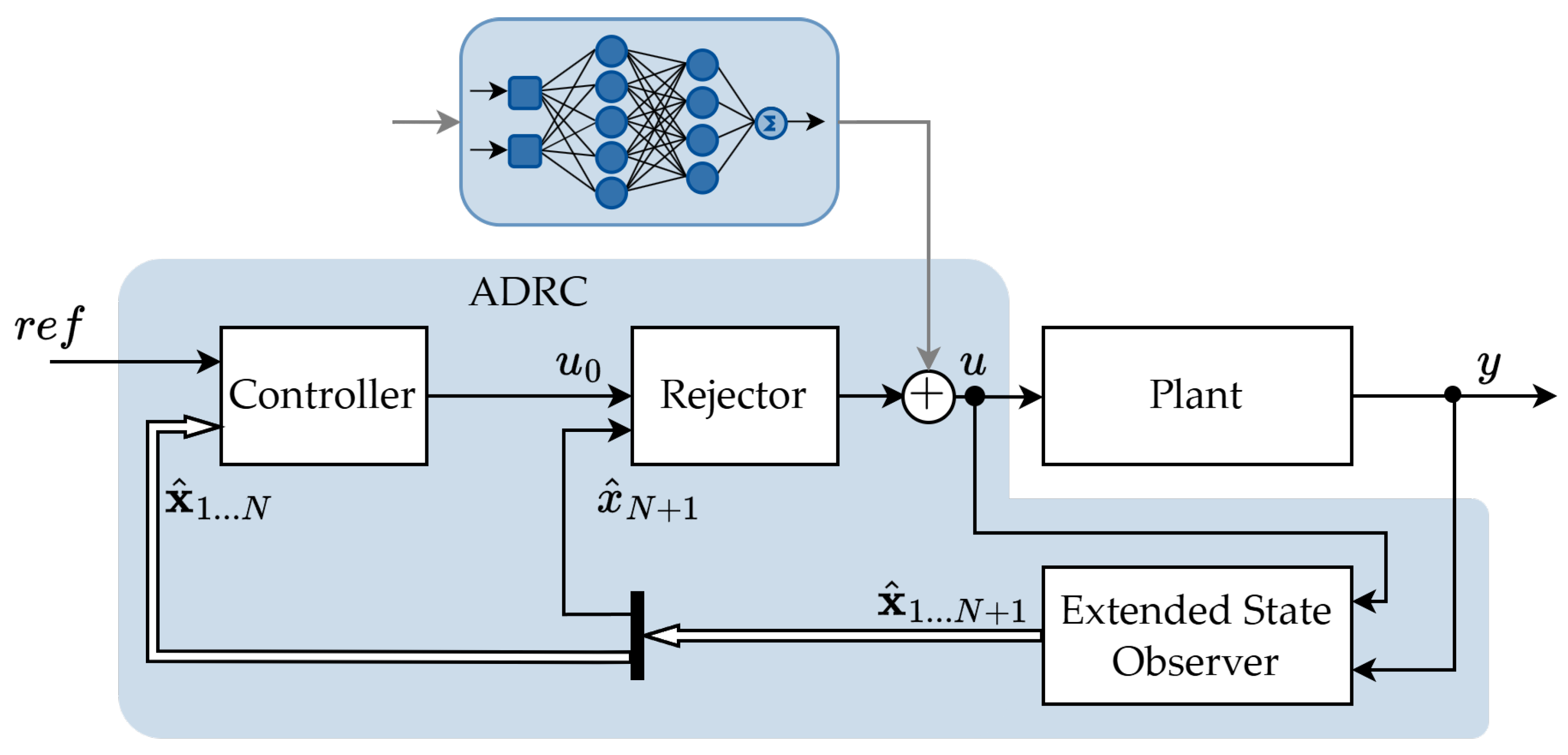
Another popular approach to the issue of outer controller modification is the neural compensation of particular uncertainties. It is based on the idea of generating a virtual signal, produced by a neural structure, which is then added as an additional component of the final control signal, which is produced by the paramount controller. The purpose of using this strategy is to compensate and level the undesired impact of external, undefined, and non-linear factors, which affect the control system response quality. It can be applied to electric drive applications, e.g., to suppress the aperiodic and harmonic disturbances without knowing the specific harmonic frequencies. It can be achieved with the online trained neural structures, e.g., RBFNN [114,115]. By employing a neural compensator inside the controller structure, the general dynamics of the inner disturbance estimation loop remains unaffected. The applied change is attached to the control signal while being unnoticed by the state observer. As a result, the ADRC strategy maintains its assets while offering a possibility to compensate for hard-to-define disruptions. The use of an online trained neural network is a satisfactory solution, as it also broadens the versatility of the ADRC strategy, as the proposed extension can be applied to a variety of different drive systems. The general idea of the described neural modifications of the ADRC controller is presented in Figure 9.

4.4. Neural Variations of Extended State Observer

The extended state observer is the most crucial component of the whole Active Disturbance Rejection approach. It is in charge of estimating the total disturbance value, but most importantly, it is responsible for delivering the actual information about other elements of the state space vector. The state observer in the ADRC strategy is based on the extended space concept, which means that all information regarding the combined disturbance estimate is separated and stored in the extended state space variable. At this point, it must be highlighted that the whole form of the space vector is estimated with the use of a Luenberger observer model. That being said, it is known that all of the space vector components are acquired using the information about the plant input (control signal) and its output only. What is also noteworthy is the fact that the Luenberger concept allows the user to shape the final dynamics of the state space variables estimation. Considering the problem of ADRC robustness expansion, it should be emphasized that it is accomplished by changing the actual values of the observer gain matrix components.
The ADRC algorithm is, by definition, based on the idea of a simplified plant model. By reducing the model of the controlled object to the cascade-integrator concept, it is possible to simplify the control law. As a result, it can be implemented using the PD controller core and utilizing the space vector as its feedback. Applying the described approach, it is possible to transfer all of the numerical complexity of the algorithm to the state observer. However, as mentioned in Section 3.1, the gain parameters of both the controller and state observer are adjusted using the bandwidth parametrization method. Thereby, the cut-off frequencies of both ADRC components share strong interdependencies with each other. The correlation between these parameters is strictly determined and should not be altered. Thus, it is clear that ADRC modifications based on the time-varying controller dynamics are not always a convenient and flawless solution. As a result, there is a significant risk that the dynamics of the outer control loop may exceed the dynamics of the internal disturbance estimation loop, which may lead to critical deterioration of the control quality or even to a sudden stability loss. Thus, having in mind the fact that the observer dynamics affect the overall quality of the conducted control process, extending the state observer with additional modifications may be a more convenient solution in many applications.
The first approach of the ESO modifications involves a neural adaptation of its gain parameters. The whole tuning process is conducted online, during the control system operation, by an additionally applied neural network structure. The purpose of applying an additional adaptation mechanism is to increase the robustness of the ADRC strategy to different disruptions. It is accomplished by dynamically changing the state observer gain coefficients. However, it must be emphasized that in many cases in the field of electric drives, a constant increase of the state observer gains is pointless. Applying a fixed rise of the state observer gain matrix elements may lead to a visible increase of the state observer sensitivity, which can make the state observer recreate the measurement noise. Consequently, it leads to control quality deterioration or stability loss. The active adaptation of the state observer gain parameters is a commonly applied approach that is widely used in the field of electric drives. It is known to improve the disturbance rejection capabilities and increase the accuracy of the state space variables estimation. As a result, the implementation of a neural-based gains adjustment mechanism leads to an increase in the final accuracy with which the plant output follows the reference state space variable trajectory [116]. The combination of the state observer with a neural network also provides promising results in the issue of non-linear phenomenon compensation. At this point, it needs to be mentioned that different neural structures can be utilized to accomplish the described task. Among all of the neural network topologies, a Radial Basis Function NN is willingly chosen. However, the application of Multilayer Perceptron Neural Networks (MLPs) or Wavelet Neural Networks is also commonly employed [117,118]. An additional adaptation mechanism of the state observer is also a feasible choice in position control application [119] as well as in more complex robotics solutions [120].
Nonetheless, not all inconveniences and uncertainties appearing in control systems can be easily eliminated by active adjustment of the state observer gains. Sometimes, it is crucial to implement a more sophisticated structure, which can tackle a specific problem by working as a separate and independent system. It is usually accomplished by creating a so-called neural compensator. The described approach derives from the idea of generating an additional, virtual signal, which is merged with a particular signal (or its part) from the state observer or the controller. Applying this method gives the designer a possibility to omit the necessity of adjusting the state observer to a particular operating scenario or phenomena. Instead, an additional neural network is in charge of estimating a missing or required part of the disturbance, which is then included in the final form of the produced signal. The described strategy is well known and also widely applicable in the field of electric drive solutions. For example, to tackle the problem of torque ripple suppression, a resonant controller is a common choice in PMSM control systems. However, applying the mentioned strategy requires having knowledge regarding the specific harmonic frequency, which is not always apparent. By applying a modified form of the ESO with RBFNN as a neural compensator, there is a chance to achieve good rejection properties and ripple disturbance suppression for a wide range of possible harmonic frequencies [121]. Sometimes, those capabilities of the control system play a crucial role in terms of operating the drive with low speed. Then, after applying a neural compensator inside the state observer, the ESO is responsible for estimating low-frequency disturbances, while torque harmonic disruption, caused by cogging torque or the non-linearity of the power converter, is obtained with the use of a neural network. Then, all of the disruption components are added and compensated [122]. In the case of a neural compensator, there is also a possibility to use different neural network topologies. For instance, a simple Adaptive Linear Neuron (ADALINE) can be used to estimate and compensate various periodic harmonics that may occur in the current control loop of the drive system. These disruptions cannot be captured by the state observer because of its limited bandwidth. By applying a neural compensator inside the state observer, it is feasible to suppress all of the aperiodic and periodic disturbances in the drive current control loop [123]. The general idea of the above-mentioned state observer modifications is presented in Figure 10.
However, all of the above-mentioned neural extensions are mainly based on a simple idea of adjusting the state observer dynamics in several ways or affecting a particular state space variable so that a specific kind of disturbance can be compensated more effectively. However, there is also an opportunity to employ a more sophisticated tuning mechanism to provide better dynamics, depending on different operating conditions. For example, an MLP neural network can be utilized to analyze different quality indicators. Each of them focuses on a different aspect of the conducted control process, e.g., estimation error or a particular state space variable. In the described solution, the neural network analyzes the information gathered from the quality criteria and decides which set of predefined state observer gains should be applied to improve the quality of the control system response [124]. There are also some applications that use even more complex solutions by using two neural networks with an action-dependent heuristic dynamic programming strategy to provide online self-tuning of the state observer [125].
Summarizing all of the presented considerations, it is visible that neural networks are capable of improving the overall quality of the ADRC algorithm. By applying a neural extension of the state observer, there is a possibility to impact the general dynamics of particular state space variables estimation or the general system behavior. All of the presented solutions are meant to increase the general control system flexibility and its robustness to different types of disturbances.

4.5. Hybrid Solutions Based on ADRC

The solutions presented in previous sections highlight specific ADRC modifications focused on solving precisely defined problems. In the case of Extended State Observer extensions, neural networks are employed to compensate for some phenomena by affecting a particular state space variable. They can also change the overall dynamics of the observer to provide a better system response during dynamic states of the drive. Those solutions are adequate if there is a precisely determined goal that can be achieved by affecting a particular part of the ADRC (e.g., compensating harmonic disturbances). However, in the case of the ADRC strategy, its versatility allows the user to equip the algorithm with an additional extension by applying a hybrid controller topology. The presented approach does not demand that the control system designer have specific knowledge of a particular disturbance type. Apparently, it is a feasible choice when the robustness of the algorithm should be increased or when there is a need to compensate some kind of disturbance in general. The hybrid controller topology relies on two parallel controllers or structures, working simultaneously. Then, the outputs of each structure are added to each other, which forms the final form of the control signal. The general idea of the hybrid ADRC controller is presented in Figure 11.
This approach is useful when a specific form of disturbance remains unnoticed from the point of view of the state observer. The proposed topology can also be used as a separate disturbance estimator. As a result, the order of the state observer can be reduced, which simplifies its tuning process [126]. The PMSM drives, on the other hand, are time-varying non-linear systems, which face parameters variations and non-linear friction. Using the hybrid ADRC controller equipped with an RBF neural network, the disturbance estimation process can be accelerated, which has a positive impact on minimizing the estimation error [127]. Hybrid structures in these PMSM drive systems can also be employed to improve the poor tracking performance caused by the mismatch between rotor flux linkage parameter and speed loop parameter, which is also a common problem [128]. In some particular cases, the hybrid topology can be used to compensate for some typical inconveniences which are caused by the unknown nature of the estimated total disturbance. In the case of the research described in [129], the study proposes a neural network designed to compensate for a current-control loop by using the estimated speed derivative value. As a result, the proposed solution allows the drive unit to operate under more complex conditions. In other scenarios, due to the motor parametrization inaccuracy, excessive speed fluctuations can be observed in some PMSM drive systems. The applied neural network is capable of adjusting the parameters of both the controller and state observer at once to reduce the steady-state speed fluctuations and reliability problems [130]. In some cases, it is also convenient to equip a conventional control system with an ADRC controller by using the hybrid topology so that the dynamic performance or additional robustness can be gained. For instance, the combination of a back-propagation neural network with PID and the ADRC technique in a variable pitch controller in a wind turbine allows for observing the state and uncertain disturbance of the system. Consequently, the amplitude of the pitch angle can be reduced, and the speed response is improved [131]. All of the solutions presented above have one main goal in common, which is a visible increase in the ADRC robustness and enhancement of its universality. Using the hybrid solutions to achieve the goal is a general approach, which may provide satisfying results in many scenarios.

5. Hardware Implementations of ADRC Algorithm for Electric Drives

The universality of the ADRC technique broadens its range of applications across many fields in industry, academia, and research and development. The algorithm’s comprehensiveness makes it suitable not only for electric-drive applications, e.g., electric vehicles or wind turbines, but also for many different control solutions. It can be widely applied to control multilayer and complex objects or different technological processes—for example, a vessel autopilot presented earlier in this paper. Each of those applications requires a hardware implementation of the control strategy to make it usable by the executive part of the controlled process.
Considering the electric drive utilization of the ADRC technique, one of the most common choices in this field is a Digital Signal Processor (DSP), which is often specifically designed for electric drive trains. An example of such a processing unit is a Texas Instruments TMS32F28xx series device. The mentioned microprocessor provides excellent performance and high accuracy in numerical operations. The mentioned features are extremely important for controlling such a dynamic plant as an electric motor. Despite the mentioned features, DSP units are also equipped with several built-in peripheral structures, including high-accuracy digital-to-analog and analog-to-digital converters and a variety of timer units. These internal structures are an inseparable component of a modern control system. They provide the possibility to cooperate with external measurement systems and sensors, but they are also responsible for generating high-frequency control signals to control even multilayer inverters or power converters. What is also noteworthy is that digital signal processors are often equipped with an interrupt-prioritization mechanism, which is a crucial component of a high-dynamic control system. For the electric drive control unit, it is mandatory to perform specific operations, e.g., speed or current measurement, within a strict time window, which must be accomplished using external or timer interrupts. Solutions based on DSPs are widely verified and willingly implemented in many electric drive applications [56,132,133].
In case of scientific or design-focused solutions and applications, e.g., in Research and Development departments, the feasibility and facility of the used hardware are critical factors. It allows scientists and engineers to quickly reconfigure the hardware of the laboratory test bench. Thereupon, for the development and assessment of new algorithms and control techniques, rapid prototyping systems are also widely used across many fields. One of the most common devices in the field of electric drive prototyping is the dSpace company, e.g., a universal numerical platform supplied with high-performance DSP and FPGA units, such as dSpace MicroLabBox or dSpace 1103 and 1104 numerical cards. The mentioned platforms ensure all of the above-mentioned demands and requirements that research and development activity enforces. Moreover, they combine all of the DSPs’ strengths with the ability to freely configure the laboratory stand’s hardware components, allowing them to be fully adjusted to specific experiments and the user’s needs. Unlike a standalone digital signal processor, rapid prototyping units can be programmed and configured using high-level programming languages and graphical interfaces, which simplify the design and development process [58,121,125].
On the other hand, the solutions described above are complex, sophisticated numerical platforms that focus on providing high performance, a wide range of configurations, and built-in tools in a professional manner. They offer users an incredibly broad spectrum of industrial and scientific applications. However, the delivered options are expensive tools that are not required in any kind of control system. A standalone DSP forces the user to deploy the designed algorithm using a low-level programming language, which, in the case of sophisticated processing units, is not a feasible or easy task, especially considering amateur applications. Thus, due to the constant growth and development of microprocessing techniques, it is now possible to implement the ADRC structure on a low-cost microcontroller. The proposed devices are usually easy to use and capable of managing even more complex control algorithms than ADRC [134,135]. On the other hand, when it comes to controlling an elaborate technological process comprising several drives and other actuators, the ADRC algorithm can be easily implemented in a Programmable Logic Controller (PLC), which is a common choice for industrial control devices. It offers the possibility of easily integrating and engaging the ADRC algorithm with the further part of the controlled machine or technological path [136,137,138].
In the case of a modern automation system, the hardware layer more often reaches for a Field-Programmable Gate Array (FPGA) processing unit. These devices ensure parallel data-processing capabilities, which are a promising solution. It broadens a control system’s potential, especially when it comes to high numerical complexity algorithms. In the case of electric drive applications, the executive devices are forced to handle quick data acquisition, including operating various sensors and signal filters, to conduct numerical operations of the main control algorithm and to manage the communication procedures with external and paramount control devices. Despite the mentioned obligations, a final stage of each numerical step accomplished by the processing unit includes the need to generate several high-frequency control signals, which are then passed to, e.g., power converters. Due to a visible trend of expanding conventional control approaches with artificial intelligence tools, at some point, there might be a timing problem. Due to the necessity of providing several numerical tasks, handling interrupts, and managing communication channels with other devices, there might be a scenario where the numerical resources of a standard procedural device (e.g., a digital signal processor or a microcontroller) are insufficient. The need to execute specific operations within strictly defined time windows, combined with the high computational complexity of modern algorithms, requires the use of FPGA units as standard hardware in today’s control platforms [139,140,141].
Employing FPGA devices as standalone processing units of control platforms implicates some negative consequences. FPGA matrices are by definition not equipped with internal peripherals, which are essential for managing communication and operation with external executive devices. Moreover, programming FPGAs often involves using low-level programming languages, which is a risky approach. That is because an FPGA, unlike a DSP, is a physically configurable electronic circuit. Hence, even a slight mistake in the built software implies a physical change in the FPGA’s electronic circuitry. Thus, making that mistake may cause internal damage to the programmable gate array. Given the above, when designing a modern control system, the hardware layer typically consists of both DSP and FPGA working simultaneously. The overall diagram of the control platform topology for the electric drive application is presented in Figure 12.
Usually, the FPGA processing unit is responsible for collecting and processing data, which are acquired from the measuring system and sensors. Moreover, it is also in charge of generating several high-frequency control signals, which are directly passed to the executive part of the drive controller (power converter). However, numerical operations related to the implemented control algorithm are accomplished by the Digital Signal Processor. Due to its high performance and built-in floating-point unit, it is capable of handling complex, double- and single-precision data processing instructions. In addition, it often manages communication by receiving commands from paramount controllers and sending information on the current status of a control path. The current development of micro-processing techniques broadens the possibility of using specifically designed libraries and tools to handle artificial intelligence algorithms. There are also dedicated extensions, allowing the user to implement a deep-learning neural network on a low-level microcontroller, which gives the designers the possibility to include deep-learning based algorithms in real-time operating systems. As a result, the implementation of the ADRC algorithms in previously described solutions, including neural network modifications, becomes increasingly feasible [57,142]. The above-mentioned development of microprocessors is also visible in low-cost devices. For example, ARM processors are today often equipped with floating-point units, which makes them also an eligible tool in terms of modern, AI-based control system implementation, which can also be combined with another FPGA device [143].

6. Analysis of Dynamic Properties and Robustness in Application for Electric Drive with Elastic Shaft—An Example

6.1. Mathematical Description of the Model and Numerical Tests

This paper presents the history of the ADRC algorithm, including its main principles and the fundamental difference in the control system design path. The algorithm proposed by Han and Gao offers excellent dynamic properties combined with robustness. Hence, the purpose of both numerical and experimental verification (presented below) is to assess the actual behavior of the two-mass drive unit, including its robustness against the inaccuracies that occurred during drive operation. The proposed tests constitute a reference point for future scientific papers.
To evaluate the dynamic properties and the robustness of the ADRC algorithm with regard to an electric drive system, a two-mass drive is considered a controlled plant. The two-mass system is a drive unit that consists of three rotational masses. Each of them represents the electric motor, the flexible shaft used to transfer the electromagnetic torque, and the load machine, respectively. The described combination is considered a drive system with a sophisticated mechanical part, which can be represented with the diagram shown in Figure 13.
For the sake of the scientific research, the load machine is substituted with another electric motor. That combination provides the opportunity to generate additional load torque and enforce an unfavorable operating condition. What is more, the used shaft is unnecessarily long and thin. The reason is to introduce additional torsional vibrations into the drive system, thereby worsening the working scenario—that is, to conduct a viable verification of the ADRC response quality. The mathematical description of the analyzed plant can be expressed using a state-space equation [144,145]:
d d t ω 1 ( t ) ω 2 ( t ) T t ( t ) = 0 0 1 T 1 0 0 1 T 2 1 T c 1 T c 0 ω 1 ( t ) ω 2 ( t ) T t ( t ) + 1 T 1 0 0 T e + 0 1 T 2 0 T l .
For the purpose of numerical tests of the ADRC algorithm, the mathematical description of the controlled object is expressed in the Laplace domain. Thus, each of the rotational masses is described with the use of an integrator block, which represents a particular drive component. Each integrator block is described by an independent mechanical time constant, which directly corresponds to the actual inertia of the rotating element of the drive. Considering Equation (12), the final form of the triple-integrator two-mass drive representation can be expressed as shown in Figure 14.
The inertia of each mass, presented in Figure 14, takes a consecutive value:
  • T 1 = 0.0281 s;
  • T 2 = 0.0281 s;
  • T c = 0.0017 s.
The real control system of the described two-mass drive unit is accomplished based on the cascade control structure. That being said, it is known that in order to provide control on the generated electromagnetic torque, the inner control loop uses the current controller with actual current feedback. However, to ensure transparency in the conducted verification, all components responsible for current generation are included in an Electromagnetic Torque Generation Loop representation block. It is accomplished with the use of a first-order inertial block and can be described with Equation (13):
G e ( p ) = 1 T e l p + 1 ,
where T e l = 0.0013 s is an electromagnetic time constant of the implemented control loop. The reference trajectory of the controlled state space variable, which is the actual speed of the load machine, is determined with the following parameters:
  • a m p = 0.4 ω N ;
  • f s = 0.1 Hz.
where a m p is an amplitude, and f s is the frequency of the reference trajectory. However, due to the inertia of mechanical components, the reference signal is passed through the reference filter to adjust its trajectory so that it can be physically achieved by the drive unit. The whole numerical verification is conducted in Matlab/Simulink environment 2025b. A thorough mathematical description of the implemented control strategy is described in detail in [25]. The general diagram of the applied control structure is presented in Figure 15.
During numerical tests, a bandwidth of the controller ω c and of the state observer ω o b s are defined with a relationship ω o b s = 9 ω c . The default cut-off frequency of the state observer is equal to w o b s = 600 s 1 . The controlled state space variable (and the output of the controlled plant) is a load machine speed, which is denoted by ω 2 .
The undeniable prevalence of the ADRC strategy is its robustness to time-varying plant parameters. Thus, the proposed numerical verification of the algorithm involves the comparison of the plant response with the nominal plant parameters and a significantly increased inertia of the load machine. The first attempt shows the system behavior under nominal plant parameters. To increase the validity of the conducted tests, an additional load torque is applied for a short period every second speed return. It is equal to T l = 0.6 T e N , and it lasts t = 2 s. Obtained transients are presented in Figure 16.
The analysis of the presented speed transients confirms the excellent dynamics of the ADRC strategy. It follows a reference trajectory accurately. Moreover, the reaction of the control system to the additional load torque is also satisfactory. An occurred control error is almost immediately eliminated when the load torque is both attached and released. During the second attempt, to simulate the time-varying nature of the object combined with an unfavorable operating scenario, the mechanical time constant of the load machine is significantly increased and equals T 2 = 3 T 2 N , where T 2 N is the nominal mechanical time constant of the load machine. The parameters of the ADRC structure remain unchanged. The obtained speed transients are presented in Figure 17.
The analysis of the obtained results confirms the robustness of the ADRC strategy. The actual response of the load machine speed is different from that during the first attempt of the conducted simulation tests. There is a visible speed lurch during every speed return (steady-state transition). However, the occurred lurch is not significant, which, in some cases, may be considered an eligible response. On the other hand, considering the sophisticated structure of the two-mass drive and the long-term operation perspective, the speed lurch is an unfavorable phenomenon, which should be mitigated, as it can lead to mechanical failure of the shaft in long-term operation. The electromagnetic and torsional torques, obtained during the second attempt, are presented in Figure 18.
The most common types of modifications to the ADRC, described earlier in this paper, involve modifying the state-feedback controller and the extended state observer separately. Moreover, based on the literature analysis, there is also a “one knob” tuning approach that relates the controller and the state observer dynamics. Thus, further analysis of the ADRC includes the system’s reaction to three types of modified dynamics in the disturbance rejection algorithm. All consecutive numerical tests assume a scenario with an increased mechanical time constant of the controlled object so that the robustness of the algorithm can be examined.
The first attempt involves modifications to the state observer dynamics and the impact of the accuracy of the state-space vector estimate on the overall behavior of the control system. During this approach, three situations are considered. The first one includes the observer bandwidth used during the first two tests, which is considered a nominal observer bandwidth w o b s N . Then, the impact of the increased ω o b s = 1.5 ω o b s N , and decreased ω o b s = 0.5 ω o b s N observer cut-off frequency, are verified. The obtained results are presented in Figure 19.
Having compared the acquired results, shown in the zoom-in (Figure 20), it can be observed that increasing the state observer dynamics has a positive impact on the overall response of the controlled plant. The lurch, visible during the steady-state transition t = 10.2 s, is visibly mitigated. Simulation results confirm that the general quality of the control system can be shaped by changing the dynamics of the state observer. However, while increasing its dynamics, it is crucial to verify the moment when the state observer starts to recreate the measurement noise, as it is an extremely dangerous phenomenon, which may lead to notable deterioration of the plant response or even to a sudden stability loss.
A second approach described in this paper concerns the dynamics of the state-feedback controller. Just as in the case of the state observer, the reference tests involve a nominal bandwidth of the state-feedback, which is also used during the first two attempts. It is denoted by ω c N . Then, during conducted simulation tests, two scenarios are analyzed. The first one features a decreased value of the controller cut-off frequency, which is equal to ω c = 0.5 ω c N , and the second test analyzes the impact of the increased controller dynamics, which is equal to ω c = 1.5 ω c N . The acquired speed transients are presented in Figure 21.
The results of the considered simulation also confirm that the overall plant response can be modified by changing the state-feedback controller form. The response of the plant during dynamic states of the drive, shown in Figure 22, also proves that the reaction of the system is visibly improved. The load machine speed converges to its reference trajectory during the steady-state transition with no overshoot. Moreover, the response time and the speed deviation during load torque attachment and release are significantly improved. Nonetheless, it is crucial to emphasize that changing the dynamics of the controller itself may lead to a situation where the overall controller’s dynamics exceeds the state-observer’s one. In that case, the control system loses stability immediately, as the relationship between the outer and inner loops’ dynamics is disrupted.
A third approach of shaping ADRC dynamics is based on the idea defined as a “one-knob tuning” approach in which the relationship between the controller and state observer bandwidths remains fixed. During the following part of numerical tests, the cut-off frequencies of both components are described with the dependency ω o b s = 9 ω c . Then, the general system dynamics is shaped with regard to the observer dynamics. The carried attempt compares the response of the system with the increased mechanical time constant of the load machine and default ω o b s = ω o b s N and increased ω o b s = 1.5 ω o b s N ADRC dynamics. The obtained results are presented in Figure 23.
The analysis of transients zoom-in (Figure 24) shows that the dynamics of the system can be significantly improved when the third approach is applied. Having compared acquired transients with the ones from previous tests, it is seen that the system’s reaction to the occurrence of additional load torque is notably improved. The load machine speed converges to the reference level almost immediately, while its deviation caused by the load torque attachment or release is visibly smaller. Moreover, the controlled state-space variable follows the reference trajectory during speed return with a barely visible control error, which also confirms the excellent dynamic properties of the ADRC algorithm and the feasibility of its potential adjustment to a changed operating scenario.

6.2. Experiment

The experimental verification of the ADRC algorithm is conducted on a laboratory test bench with a modern two-mass drive unit. It is made up of two brushless D.C. (BLDC) motors, which are coupled to each other using a long, flexible coupling. The flexible connection consists of the shaft itself, the flywheel weight interface, and several elastic clutches. The electric motors used on the test bench are 0.25 kW Teknic Hudson BLDC motors with built-in Hall sensors, which provide actual rotor position information. The motors work in trapezoidal commutation mode, but they are also adjusted to handle sinusoidal commutation. The power converter is responsible for powering the motor and managing information from the Hall sensors. The load machine is connected to the power contactor, which attaches load resistors to the load machine windings, allowing the generation of additional load torque. The current measurement is performed using the LEM CAS 25-NP current transducer, which is mounted on the DC-Bus. The power electronics part is powered by a 48 V Power Supply. The numerical execution of the implemented algorithm is carried out on a Digital Signal Processor, which the dSpace 1103 Rapid Prototyping System is equipped with. It receives the information regarding current and rotational speeds of both motors, and it is in charge of calculating the implemented algorithm, producing a final form of a control signal, and controlling the load torque generation circuit. The entire course of the experiment is supervised with a paramount PC with Control Desk 3.7.2 Software. The general structure of the laboratory stand is shown in Figure 25.
The mechanical time constant of each component remains the same as in numerical verification section. The basic parameters of the used test bench are collected in Table 1.
Real-life pictures of the two-mass drive and its control cabinet are presented in Figure 26.
The purpose of the experimental verification is to examine the robustness of the ADRC algorithm against significant changes in plant parameters. To accomplish this, two experimental attempts are conducted. The first one verifies the plant’s response when its internal parameters are considered default. Then, an additional flywheel weight is attached to the load machine shaft. As a result, the load machine inertia is visibly increased and is equal to T 2 = 3 T 2 N , where T 2 N is its nominal mechanical time constant. The parameters of the reference trajectory and moments of the additional load torque attachment and release are the same as during numerical verification. The obtained results are presented in Figure 27.
The analysis of the acquired speed transients in the overall perspective does not reveal any significant differences between the actual plant response for its different and default internal parameters. Thus, an excellent robustness of the ADRC algorithm has been confirmed experimentally. A zoom-in of the load machine speed transients is shown in Figure 28.
The detailed analysis of the speed return and behavior of the system in the face of additional load torque shows that there is only a slight deterioration of the plant response quality visible. Differences are marked with red markers in Figure 28. However, considering the overall quality of the way the controlled speed value follows the reference trajectory, the occurring deviations are negligible. The electromagnetic and torsional torque transients of the system with increased mechanical time constant of the load machine are presented in Figure 29.

7. Conclusions

Today’s technological processes face the field of automation with many challenges regarding the dynamic properties of the controlled process as well as the feasibility of its implementation and deployment. These trends tend to be visible in the field of electric drives automation. Moreover, electric drives are considered high dynamics objects by default, which does not make the task of fulfilling those expectations easier. Controlling electric motors requires providing high performance properties combined with robustness against time-varying parameters of both the plant or the external environment. Due to the sophistication of modern technological processes and machines, time-varying objects are becoming a common problem. In some specific scenarios, the control system is also required to provide adaptation capabilities, so it can detect deviations that occur and compensate them on its own. Moreover, the easiness of the algorithm implementation is also an undeniably crucial feature, which needs to be taken into account in modern automation.
The answer of the today’s Control Theory to highlighted requirements and expectations lies in the controller-oriented approach, which focuses on creating a versatile algorithm, which is not dependent on the plant model. Considering particular assumptions, it is possible to describe the controlled process in the form of a cascade integrator block, where all of the internal and external disruptions and modeling uncertainties are treated as a total disturbance. The described approach is a foundation of the Active Disturbance Rejection Control, which fulfills all of the modern automation requirements. As a result, it proves that it is possible to design a universal control strategy, which, after slight modifications to its structure, can be easily adjusted to a variety of different objects and applications, where it ensures high control accuracy. Conducted simulation and experimental tests show that if tuned properly, the ADRC features an excellent robustness against time-varying plant parameters, which is its undeniable prevalence.
Nowadays, there is a visible trend that controlled processes and machines are more sophisticated and complex. However, despite that, their control systems are still expected to deliver the same capabilities and fulfill the same requirements, as mentioned above. The Control Theory offers several variants of the ADRC strategy, which make it feasible to adjust its default form to particular applications. In the era of artificial intelligence development, there is also a visible trend to expand the ADRC with different properties using neural networks and other AI tools. Different approaches result in different features, which are linked together with one common goal: to increase the overall versatility and robustness of the disturbance rejection strategy. The purpose of this goal is to achieve a control structure that features an outstanding resilience to a variety of disturbances and disruptions of different types. Using neural networks in this field opens up a new perspective, as they allow to simplify the ADRC tuning process or generate a virtual compensating signal, which, after merging with a particular internal ADRC signal path, can compensate for distinct types of disturbances, including internal plant dynamics uncertainties, which are not involved in the internal disturbance estimation loop. Moreover, neural networks give an opportunity to equip the ADRC strategy with additional adaptation capabilities. Due to that fact, the control system automatically adjusts to the control quality deviations. All of that can be achieved without the necessity of using an additional reference model that delivers the information regarding the expected plant behavior, as it is usually accomplished in a conventional adaptive control approach. Due to relentless improvement and development of the micro-processing technique, the implementation of neural structures becomes feasible. They can broaden the dynamic properties of the ADRC. As a result, the ADRC is not excluded from the body of possible control approaches, even in the case of complex, multilayer objects. Additionally, it opens up the possibility to implement a neural-based ADRC even in high dynamic applications (e.g., electric drives), where the numerical time step, required to produce a following value of the control signal, is very narrow. Furthermore, considering the overall quality of the ADRC controlled two-mass drive (presented in Section 6), neural-modified ADRC variations constitute a promising base to create an ultimate control algorithm combining low numerical complexity, outstanding robustness, versatility, and adaptation capabilities.

Author Contributions

Conceptualization, G.K. and M.K.; methodology, G.K.; software, G.K.; validation, G.K., J.K. and M.K.; formal analysis, M.K.; investigation, G.K., J.K., D.D.F. and M.K.; resources, G.K., J.K., D.D.F. and M.K.; data curation, G.K., J.K., D.D.F. and M.K.; writing—original draft preparation, G.K., J.K., D.D.F. and M.K.; writing—review and editing, G.K., J.K., D.D.F. and M.K.; visualization, G.K. and J.K.; supervision M.K.; project administration, M.K.; funding acquisition, M.K. All authors have read and agreed to the published version of the manuscript.

Funding

This research received no external funding.

Data Availability Statement

The original contributions presented in the study are included in the article, further inquiries can be directed to the corresponding author.

Conflicts of Interest

The authors declare no conflicts of interest.

Abbreviations

The following abbreviations are used in this manuscript:
ADALINEAdaptive Linear Neuron
ADRActive Disturbance Rejection
ADRCActive Disturbance Rejection Control
BLDCBrushless Direct Current Motor
DRCDisturbance Rejection Control
DSPDigital Signal Processor
DTCDirect Torque Control
ESOExtended State Observer
FOCField Oriented Control
FPGAField-Programmable Gate Array
MFASModel-Following Adaptive System
MLPMultilayer Perceptron
MRACModel Reference Adaptive Control
NNNeural Network
LADRCLinear Active Disturbance Rejection Control
LESOLinear Extended State Observer
PMSGPermanent Magnet Synchronous Generator
PMSMPermanent Magnet Synchronous Motor
RBFNNRadial Basis Function Neural Network
TDTracking Differentiator

References

  1. Liang, J.; Zhou, P.; Xu, H.; Chen, X. Structure Design and Process Optimization of Electric Spindle Motor for High Precision CNC Machine Tools. In Proceedings of the 2025 IEEE 8th International Electrical and Energy Conference (CIEEC), Changsha, China, 16–18 May 2025; pp. 3428–3433. [Google Scholar] [CrossRef]
  2. Liu, C.C.; Chen, M.N.; Liu, C.S. High-Precision Motion Control of a Robotic Arm Using the Manifold Deformation Design Scheme. IEEE Access 2025, 13, 214721–214739. [Google Scholar] [CrossRef]
  3. Liao, M.; Dong, L.; Jin, L.; Wang, S. Study on Rotational Speed Feedback Torque Control for Wind Turbine Generator System. In Proceedings of the 2009 International Conference on Energy and Environment Technology, Guilin, China, 16–18 October 2009; Volume 1, pp. 853–856. [Google Scholar] [CrossRef]
  4. Dost, P.; Sourkounis, C. Influence of the inverter control-system to the mechanical and electrical behaviour of an electric vehicle modulated as a two-mass-system. In Proceedings of the 2012 20th Mediterranean Conference on Control & Automation (MED), Barcelona, Spain, 3–6 July 2012; pp. 1099–1104. [Google Scholar] [CrossRef]
  5. Saha, A.; Dash, P.; Babu, N.R.; Chiranjeevi, T.; Venkateswararao, B.; Knypiński, L. Impact of Spotted Hyena Optimized Cascade Controller in Load Frequency Control of Wave-Solar-Double Compensated Capacitive Energy Storage Based Interconnected Power System. Energies 2022, 15, 6959. [Google Scholar] [CrossRef]
  6. Jain, J.K.; Ghosh, S.; Maity, S.; Dworak, P. PI controller design for indirect vector controlled induction motor: A decoupling approach. ISA Trans. 2017, 70, 378–388. [Google Scholar] [CrossRef] [PubMed]
  7. Kaloust, J.; Qu, Z. Robust control design for nonlinear uncertain systems with an unknown time-varying control direction. IEEE Trans. Autom. Control 1997, 42, 393–399. [Google Scholar] [CrossRef]
  8. Coleman, C.; Godbole, D. A comparison of robustness: Fuzzy logic, PID, and sliding mode control. In Proceedings of the 1994 IEEE 3rd International Fuzzy Systems Conference, Orlando, FL, USA, 26–29 June 1994; Volume 3, pp. 1654–1659. [Google Scholar] [CrossRef]
  9. Niewiara, L.J.; Surus, R.; Tarczewski, T. Computationally Efficient Gradient Enhanced FCS-MPCC with Reduced Torque Ripple for a Reluctance Synchronous Motor Drive. IEEE Trans. Ind. Electron. 2026, 73, 5198–5210. [Google Scholar] [CrossRef]
  10. Derugo, P.; Szabat, K.; Pajchrowski, T.; Zawirski, K. Fuzzy Adaptive Type II Controller for Two-Mass System. Energies 2022, 15, 419. [Google Scholar] [CrossRef]
  11. Cu, D.T.L.; Nam, G.V.; Dong, D.V. Robust Sliding Mode Control for Blushless DC Motor with Consideration of Load Torque. In Proceedings of the 2024 9th International Conference on Applying New Technology in Green Buildings (ATiGB), Danang, Vietnam, 30–31 August 2024; pp. 48–52. [Google Scholar] [CrossRef]
  12. Slavov, T.; Taralova, I.; Neykov, R.; Mollov, L. Gain Scheduling Real Time Control of Tank Water Level by PLC. In Proceedings of the 2025 International Conference Automatics, Robotics and Artificial Intelligence (ICARAI), Sozopol, Bulgaria, 13–15 June 2025; pp. 1–6. [Google Scholar] [CrossRef]
  13. Maddi, A.; Guessoum, A.; Berkani, D. Improvement tracking performances of adaptive model following control systems with unknown disturbances. In Proceedings of the 2015 6th International Conference on Modeling, Simulation, and Applied Optimization (ICMSAO), Istanbul, Turkey, 27–29 May 2015; pp. 1–6. [Google Scholar] [CrossRef]
  14. Liu, X.H.; Yin, J.; Wang, Y.H. Adaptive Model Following Control for a Class of Onlinear System Based on the Newton Iterative Algorithm. In Proceedings of the 2005 International Conference on Machine Learning and Cybernetics, Guangzhou, China, 18–21 August 2005; Volume 1, pp. 649–653. [Google Scholar] [CrossRef]
  15. Cuong, N.D.; Lanh, N.V.; Huyen, D.V. Design of MRAS-based adaptive control systems. In Proceedings of the 2013 International Conference on Control, Automation and Information Sciences (ICCAIS), Nha Trang, Vietnam, 25–28 November 2013; pp. 79–84. [Google Scholar] [CrossRef]
  16. Qiang, H. The design of model reference adaptive control. In Proceedings of the International Conference on Automatic Control and Artificial Intelligence (ACAI 2012), Xiamen, China, 24–26 March 2012; pp. 2092–2095. [Google Scholar] [CrossRef]
  17. Szczepański, R.; Tarczewski, T.; Grzesiak, L. Selection of reference model for adaptive PMSM drive based on MRAC approach. Bull. Pol. Acad. Sci. Tech. Sci. 2024, 72, e149177. [Google Scholar] [CrossRef]
  18. Miniach, M.; Orlowska-Kowalska, T. Innovative Extended Kalman Filter in a Coherent System for Detection and Compensation of Various Current Sensor Faults in the Induction Motor Drive. IEEE Trans. Ind. Electron. 2025, 72, 7772–7784. [Google Scholar] [CrossRef]
  19. Oliszewski, S.; Pawlak, M.; Dybkowski, M. DC-Link Capacitors Online Condition Monitoring Using Repetitive RLS in Hybrid-Electric Aircraft. IEEE Access 2025, 13, 131166–131176. [Google Scholar] [CrossRef]
  20. Malarczyk, M.; Zychlewicz, M.; Stanislawski, R.; Kaminski, M. Low-Cost Implementation of an Adaptive Neural Network Controller for a Drive with an Elastic Shaft. Signals 2023, 4, 56–72. [Google Scholar] [CrossRef]
  21. Zhang, M.; Wang, X.; Liu, M. Adaptive PID control based on RBF neural network identification. In Proceedings of the 17th IEEE International Conference on Tools with Artificial Intelligence (ICTAI’05), Hong Kong, China, 14–16 November 2005; pp. 3–683. [Google Scholar] [CrossRef]
  22. Xu, R.; Liu, J.; Lin, X.; Liu, Z.; Yan, F.; Gao, Y. Autotuned Nonlinear Extended State Observer-Based Fixed-Time Control for Motor-Drive Servo Systems. IEEE Trans. Power Electron. 2025, 40, 14536–14546. [Google Scholar] [CrossRef]
  23. Stanislawski, R.; Tapamo, J.R.; Kaminski, M. A Hybrid Adaptive Controller Applied for Oscillating System. Energies 2022, 15, 6265. [Google Scholar] [CrossRef]
  24. Stanislawski, R.; Tapamo, J.R.; Kaminski, M. Virtual Signal Calculation Using Radial Neural Model Applied in a State Controller of a Two-Mass System. Energies 2023, 16, 5629. [Google Scholar] [CrossRef]
  25. Kaczmarczyk, G.; Stanislawski, R.; Kaminski, M.; Kasprzak, K.; Ferreira, D.D. A neural-enhanced active disturbance load-side speed control of an electric drive with a flexible link. Arch. Electr. Eng. 2025, 74, 269–289. [Google Scholar] [CrossRef]
  26. Frankiewicz, O.; Skowron, M.; Jarosz, J.J.; Weisse, S.; Valire, J.; Szabat, K. Classification of Rolling Bearing Defects Based on the Direct Analysis of Phase Currents. Energies 2025, 18, 2645. [Google Scholar] [CrossRef]
  27. Jarosz, J.J.; Skowron, M.; Frankiewicz, O.; Wolkiewicz, M.; Weisse, S.; Valire, J.; Szabat, K. Diagnostic Signal Acquisition Time Reduction Technique in the Induction Motor Fault Detection and Localization Based on SOM-CNN. Electronics 2025, 14, 2373. [Google Scholar] [CrossRef]
  28. Żychlewicz, M.; Kamiński, M. The LSTM Models with Gated Recurrent Unit Applied for Shaft Torque Estimation of Two-Mass System. In Proceedings of the 2025 29th International Conference on Methods and Models in Automation and Robotics (MMAR), Miedzyzdroje, Poland, 26–29 August 2025; pp. 295–300. [Google Scholar] [CrossRef]
  29. Pietrzak, P.; Wolkiewicz, M.; Kotarski, J. Low-Cost Microcontroller-Based System for Condition Monitoring of Permanent-Magnet Synchronous Motor Stator Windings. Electronics 2024, 13, 2975. [Google Scholar] [CrossRef]
  30. Kaczmarczyk, G.; Stanislawski, R.; Kaminski, M. Deep-Learning Techniques Applied for State-Variables Estimation of Two-Mass System. Energies 2025, 18, 568. [Google Scholar] [CrossRef]
  31. Gao, Z. Active disturbance rejection control: From an enduring idea to an emerging technology. In Proceedings of the 2015 10th International Workshop on Robot Motion and Control (RoMoCo), Poznań, Poland, 6–8 July 2015; pp. 269–282. [Google Scholar] [CrossRef]
  32. Gao, Z. On the centrality of disturbance rejection in automatic control. ISA Trans. 2014, 53, 850–857. [Google Scholar] [CrossRef]
  33. Han, J. Control theory: The doctrine of model or the doctrine of control? Syst. Sci. Math. 1989, 9, 328–335. (In Chinese) [Google Scholar]
  34. Han, J. The extended state observer of a class of uncertain systems. Control Decis. 1995, 10, 85–88. [Google Scholar]
  35. Huang, Y.; Xu, K.; Han, J.; Lam, J. Flight control design using extended state observer and non-smooth feedback. In Proceedings of the 40th IEEE Conference on Decision and Control (Cat. No.01CH37228), Orlando, FL, USA, 4–7 December 2001; Volume 1, pp. 223–228. [Google Scholar] [CrossRef]
  36. Gao, Z. Scaling and bandwidth-parameterization based controller tuning. In Proceedings of the 2003 American Control Conference, Denver, CO, USA, 4–6 June 2003; Volume 6, pp. 4989–4996. [Google Scholar] [CrossRef]
  37. Radke, A.; Gao, Z. A survey of state and disturbance observers for practitioners. In Proceedings of the 2006 American Control Conference, Minneapolis, MN, USA, 14–16 June 2006; p. 6. [Google Scholar] [CrossRef]
  38. Xue, W.; Gao, Z. On the augmentation of Luenberger Observer-based state feedback design for better robustness and disturbance rejection. In Proceedings of the 2015 American Control Conference (ACC), Chicago, IL, USA, 1–3 July 2015; pp. 3937–3943. [Google Scholar] [CrossRef]
  39. Dong, L.; Kandula, P.; Gao, Z.; Wang, D. On a robust control system design for an electric power assist steering system. In Proceedings of the 2010 American Control Conference, Baltimore, MD, USA, 30 June–2 July 2010; pp. 5356–5361. [Google Scholar] [CrossRef]
  40. Yang, H.; Jiang, Q.; Zhong, Y. Active-disturbance rejection control and its application to solar PV DC-DC converter. In Proceedings of the 2010 3rd International Conference on Advanced Computer Theory and Engineering (ICACTE), Chengdu, China, 20–22 August 2010; Volume 3, pp. V3-170–V3-173. [Google Scholar] [CrossRef]
  41. Long, M.; Li, G.; Chen, S.; Fu, Y. ADR algorithm applied in electro-hydraulic servo system. In Proceedings of the 2011 International Conference on Electronic & Mechanical Engineering and Information Technology, Harbin, China, 12–14 August 2011; Volume 4, pp. 1888–1891. [Google Scholar] [CrossRef]
  42. Li, X.; Chen, W. Application of active disturbance rejection controller for high precision servo system. In Proceedings of the 2011 International Conference on Mechatronic Science, Electric Engineering and Computer (MEC), Jilin, China, 19–22 August 2011; pp. 2467–2470. [Google Scholar] [CrossRef]
  43. Zheng, Q.; Gao, Z. On practical applications of active disturbance rejection control. In Proceedings of the 29th Chinese Control Conference, Beijing, China, 29–31 July 2010; pp. 6095–6100. [Google Scholar]
  44. Wang, J.; He, L.; Sun, M. Application of active disturbance rejection control to integrated flight-propulsion control. In Proceedings of the 2010 Chinese Control and Decision Conference, Xuzhou, China, 26–28 May 2010; pp. 2565–2569. [Google Scholar] [CrossRef]
  45. Lin, D.; Luo, W.; Zhang, H. Active disturbance rejection controller of BLDCM in electric vehicle. In Proceedings of the 2011 International Conference on Electrical Machines and Systems, Beijing, China, 20–23 August 2011; pp. 1–4. [Google Scholar] [CrossRef]
  46. Li, Y.; Chen, H. Application of active disturbance rejection control strategy for active front wheel steering control. In Proceedings of the 2010 International Conference on Mechanic Automation and Control Engineering, Wuhan, China, 26–28 June 2010; pp. 3566–3569. [Google Scholar] [CrossRef]
  47. Han, J. From PID to Active Disturbance Rejection Control. IEEE Trans. Ind. Electron. 2009, 56, 900–906. [Google Scholar] [CrossRef]
  48. Herbst, G.; Madonski, R. Active Disturbance Rejection Control: From Principles to Practice; Springer Nature: Cham, Switzerland, 2025. [Google Scholar] [CrossRef]
  49. Huang, C.; Yin, Y. Wind Turbine Pitch Control Based on Error-based ADRC Approach Optimized by Brain Storm Optimization Algorithm. In Proceedings of the 2019 1st International Conference on Industrial Artificial Intelligence (IAI), Shenyang, China, 23–27 July 2019; pp. 1–6. [Google Scholar] [CrossRef]
  50. Madonski, R.; Shao, S.; Zhang, H.; Gao, Z.; Yang, J.; Li, S. General error-based active disturbance rejection control for swift industrial implementations. Control Eng. Pract. 2019, 84, 218–229. [Google Scholar] [CrossRef]
  51. Kaczmarczyk, G.; Malarczyk, M.; Stanisławski, R.; Kamiński, M. Auto-Identification of Two-Mass System Parameters with Reinforcement Learning. In Proceedings of the 2025 29th International Conference on Methods and Models in Automation and Robotics (MMAR), Międzyzdroje, Poland, 26–29 August 2025; pp. 289–294. [Google Scholar] [CrossRef]
  52. Patelski, R.; Pazderski, D. Active disturbance rejection control with adaptive input gain using dynamic inversion approach. ISA Trans. 2025, 160, 248–256. [Google Scholar] [CrossRef] [PubMed]
  53. Kakodia, S.K.; Dyanamina, G.; Edpuganti, A. Enhancing Speed Response in PMSM-Fed Electric Vehicles Through Active Disturbance Rejection Controller-Based Vector Control Method. In Proceedings of the 2025 IEEE 4th International Conference on Smart Technologies for Power, Energy and Control (STPEC), Goa, India, 10–13 December 2025; pp. 1–6. [Google Scholar] [CrossRef]
  54. Deng, F.; Guan, Y. PMSM Vector Control Based on Improved ADRC. In Proceedings of the 2018 IEEE International Conference of Intelligent Robotic and Control Engineering (IRCE), Lanzhou, China, 24–27 August 2018; pp. 154–158. [Google Scholar] [CrossRef]
  55. Wang, C.; Yang, H.; Yan, J.; Lin, H.; Fang, S.; Shen, Y. Disturbance Rejection Optimization for Permanent Magnet Synchronous Motor Systems Based on Modified Linear Active Disturbance Rejection Control. In Proceedings of the 2025 IEEE International Electric Machines & Drives Conference (IEMDC), Houston, TX, USA, 18–21 May 2025; pp. 910–915. [Google Scholar] [CrossRef]
  56. Wu, H.; Gan, C.; Wang, H.; Wang, S.; Qu, R.; Liu, X. Active Disturbance Rejection Speed Control with Double-Stage-ESO Considering Aperiodic and Periodic Disturbances for PMSM Drives. IEEE Trans. Ind. Electron. 2025, 1–12. [Google Scholar] [CrossRef]
  57. Zhang, Y.; Huang, X.; Yu, W.; Xu, J. A General Formulation of Full-Decoupled Two-Degree-of-Freedom Position Controller for PMSLM Based on ADRC. IEEE Trans. Ind. Appl. 2026, 62, 1019–1028. [Google Scholar] [CrossRef]
  58. Zuo, Y.; Xie, S.; Cao, L.; Han, B.S.; Hoang, C.C.; You, C.; Chan, J.; Lee, C.H.T. A Novel Nonlinear Active Disturbance Rejection Controller for Speed Control of Electric Drives. In Proceedings of the 2022 IEEE Energy Conversion Congress and Exposition (ECCE), Detroit, MI, USA, 9–13 October 2022; pp. 1–5. [Google Scholar] [CrossRef]
  59. Tian, M.; Wang, B.; Yu, Y.; Ma, X.; Dong, Q.; Xu, D. Proportional Resonant-Based Active Disturbance Rejection Control for Speed Fluctuation Suppression of PMSM Drives. In Proceedings of the 2019 22nd International Conference on Electrical Machines and Systems (ICEMS), Harbin, China, 11–14 August 2019; pp. 1–6. [Google Scholar] [CrossRef]
  60. Zuo, Y.; Liu, C.; Fu, H.; Wang, K.; Han, S. Speed control of electrical drives using a full decoupled active disturbance rejection controller. In Proceedings of the 2016 Eleventh International Conference on Ecological Vehicles and Renewable Energies (EVER), Monte Carlo, Monaco, 6–8 April 2016; pp. 1–5. [Google Scholar] [CrossRef]
  61. Qiu, L.; Yang, K.; Luo, Y.; Li, W. Multi-Disturbances Suppression for Permanent Magnet Synchronous Motor based on Active Disturbance Rejection Model Predictive Control. In Proceedings of the 2023 IEEE International Conference on Predictive Control of Electrical Drives and Power Electronics (PRECEDE), Wuhan, China, 16–19 June 2023; pp. 1–6. [Google Scholar] [CrossRef]
  62. Prakash, A.; Bhaskar, D.V.; Ranjan, A.; Muduli, U.R. ADRC Based Speed Regulation of PMBLDC Motor Driven LEV Considering Iron-Loss Compensation. In Proceedings of the 2025 IEEE 5th International Conference on Sustainable Energy and Future Electric Transportation (SEFET), Jaipur, India, 9–12 July 2025; pp. 1–6. [Google Scholar] [CrossRef]
  63. Hezzi, A.; Elghali, S.B.; Zhou, Z.; Elbouchikhi, E.; Benbouzid, M. Linear ADRC for Speed Control of 5-Phase PMSM-based Electric Vehicles. In Proceedings of the 2020 International Conference on Electrical and Information Technologies (ICEIT), Rabat, Morocco, 4–7 March 2020; pp. 1–6. [Google Scholar] [CrossRef]
  64. Joraiche, O.; Abouloifa, A.; Elbouchikhi, E.; Lachkar, I.; Aouadi, C.; Aroudi, A.E. Performance Comparison of PID, ADRC, and Backstepping Controllers for PMSM Speed Regulation in Electric Vehicles. In Proceedings of the 2025 International Conference on Control, Automation and Diagnosis (ICCAD), Barcelona, Spain, 1–3 July 2025; pp. 1–6. [Google Scholar] [CrossRef]
  65. He, F.; Song, Z.; Wang, Q. SVPWM Vector Control with Active Disturbance Rejection for Electric Vehicle Motor. In Proceedings of the 2020 Chinese Automation Congress (CAC), Shanghai, China, 6–8 November 2020; pp. 1401–1406. [Google Scholar] [CrossRef]
  66. Cheng, Z.; Li, L.; Zhong, C.; Wang, J.; Bai, X.; Liu, J. Adaptive Hybrid Active Disturbance Rejection Speed Control for Vehicle PMSM Electric Propulsion System Under Uncertain Disturbances. IEEE Trans. Energy Convers. 2025, 40, 2870–2883. [Google Scholar] [CrossRef]
  67. Saha, S.; Kar, U.; Sen, J. Speed Tracking Cruise Control of Electric Vehicle using Active Disturbance Rejection Control. In Proceedings of the 2023 IEEE 3rd Applied Signal Processing Conference (ASPCON), Haldia, India, 24–25 November 2023; pp. 255–260. [Google Scholar] [CrossRef]
  68. Yuan, Q.; Liu, Z.; Chen, H.; Tian, Y. A cruise control for electric vehicle based on ADRC controller considering driver’s behavior. In Proceedings of the IECON 2017—43rd Annual Conference of the IEEE Industrial Electronics Society, Beijing, China, 29 October–1 November 2017; pp. 4597–4602. [Google Scholar] [CrossRef]
  69. Zhang, W.; Xu, H. Active disturbance rejection based pitch control of variable speed wind turbine. In Proceedings of the 30th Chinese Control Conference, Yantai, China, 22–24 July 2011; pp. 5094–5098. [Google Scholar]
  70. Ullah, F.; Ali, S.; Ying, D.; Saeed, A. Linear Active Disturbance Rejection Control Approach Base Pitch Angle Control of Variable Speed Wind Turbine. In Proceedings of the 2019 IEEE 2nd International Conference on Electronics Technology (ICET), Chengdu, China, 10–13 May 2019; pp. 614–618. [Google Scholar] [CrossRef]
  71. De, Z.; Shengwei, M.; Feng, L.; Jian, S. Power oscillation damping controller based on active disturbance rejection control technique for DFIG-based wind turbine generators. In Proceedings of the 26th Chinese Control and Decision Conference (2014 CCDC), Changsha, China, 31 May–2 June 2014; pp. 2749–2752. [Google Scholar] [CrossRef]
  72. Wang, Y.; Cui, W.; Tan, W. Load frequency control for power systems with wind turbine via active disturbance rejection. In Proceedings of the 2020 39th Chinese Control Conference (CCC), Shenyang, China, 27–29 July 2020; pp. 2334–2339. [Google Scholar] [CrossRef]
  73. Wang, L.; Zhang, H.; Cai, M.; Luo, Z. Active disturbance rejection power control for a floating wind turbine. In Proceedings of the 2017 29th Chinese Control And Decision Conference (CCDC), Chongqing, China, 28–30 May 2017; pp. 559–564. [Google Scholar] [CrossRef]
  74. Imad, A.; El Hani, S.; Echchaachouai, A.; Energy, A.A. Robust Active disturbance Rejection Control of a direct driven PMSG wind turbine. In Proceedings of the 2017 International Renewable and Sustainable Energy Conference (IRSEC), Tangier, Morocco, 4–7 December 2017; pp. 1–6. [Google Scholar] [CrossRef]
  75. Li, Y.; Li, H.; Cui, J.; Zhao, B. Research on Active Disturbance Rejection Control Strategy for Dual Rotor Wind Power System. In Proceedings of the 2024 4th International Conference on Energy Engineering and Power Systems (EEPS), Hangzhou, China, 9–11 August 2024; pp. 320–323. [Google Scholar] [CrossRef]
  76. Lin, S.; Xiang, L.; Lin, X.; Chen, Y.; Xiong, X. Event-triggered Active Disturbance Rejection Frequency Control for Offshore Wind Power Integration. In Proceedings of the 2025 IEEE 3rd International Conference on Power Science and Technology (ICPST), Kunming, China, 16–18 May 2025; pp. 1490–1495. [Google Scholar] [CrossRef]
  77. Tao, L.; Ma, X.; Wang, Y.; Shi, H.; Yang, W.; Wang, Z. Linear Active Disturbance Rejection Control with Deviation Differential for DC Bus Voltage in Wind Power System. In Proceedings of the 2023 IEEE Energy Conversion Congress and Exposition (ECCE), Nashville, TN, USA, 29 October–2 November 2023; pp. 301–306. [Google Scholar] [CrossRef]
  78. Wicher, B.; Brock, S. Tuning Optimization of Extended State Observer for Two Mass System with Elastic Joint and Backlash. In Proceedings of the 2018 18th International Conference on Mechatronics - Mechatronika (ME), Brno, Czech Republic, 5–7 December 2018; pp. 1–6. [Google Scholar]
  79. Wicher, B.; Brock, S. Dobór nastaw regulatora prędkości opartego o strukturę ADRC, dedykowanego dla układu dwumasowego. Przegląd Elektrotechniczny 2024, R. 100, nr 5, 49–55. [Google Scholar]
  80. Wicher, B.; Brock, S. Active Disturbance Rejection Control Based Load Side Speed Controller for Two Mass System with Backlash. In Proceedings of the 2018 IEEE 18th International Power Electronics and Motion Control Conference (PEMC), Budapest, Hungary, 26–30 August 2018; pp. 645–650. [Google Scholar] [CrossRef]
  81. Cao, J.; Li, Y.; Zhang, X.; Yang, J.; Fan, W. Torque-Type Backlash Inverse Control for an Electromechanical Actuator with Active Disturbance Rejection. IEEE Access 2023, 11, 108688–108696. [Google Scholar] [CrossRef]
  82. Wicher, B. ADRC Load Position Controller for Two Mass System with Elastic Joint and Backlash. In Proceedings of the 2018 23rd International Conference on Methods & Models in Automation & Robotics (MMAR), Miedzyzdroje, Poland, 27–30 August 2018; pp. 333–338. [Google Scholar] [CrossRef]
  83. Zhang, R.; Tong, C. A novel torsional vibration suppression approach of a two-mass main drive system of rolling mill based on active disturbance rejection control. In Proceedings of the 2005 International Conference on Control and Automation, Budapest, Hungary, 26–29 June 2005; Volume 2, pp. 1143–1148. [Google Scholar] [CrossRef]
  84. Li, P.; Wang, L.; Zhong, B.; Zhang, M. Linear Active Disturbance Rejection Control for Two-Mass Systems Via Singular Perturbation Approach. IEEE Trans. Ind. Inform. 2022, 18, 3022–3032. [Google Scholar] [CrossRef]
  85. Madonski, R. On Active Disturbance Rejection in Robotic Motion Control. Ph.D. Thesis, Poznan University of Technology, Poznań, Poland, 2016. [Google Scholar] [CrossRef]
  86. Khaled, T.A.; Akhrif, O.; Bonev, I.A. Dynamic Path Correction of an Industrial Robot Using a Distance Sensor and an ADRC Controller. IEEE/ASME Trans. Mechatron. 2021, 26, 1646–1656. [Google Scholar] [CrossRef]
  87. Yin, Y.; Li, Z.; Du, Y.; Jiao, J.; Xin, J. Active Disturbance Rejection Control Based Trajectory Tracking Method for Robotic Multi-Target Riveting Tasks. In Proceedings of the 2025 Joint International Conference on Automation-Intelligence-Safety & International Symposium on Autonomous Systems (ICAIS-ISAS), Xi’an, China, 23–25 May 2025; pp. 1–8. [Google Scholar] [CrossRef]
  88. Xue, W.; Madonski, R.; Lakomy, K.; Gao, Z.; Huang, Y. Add-On Module of Active Disturbance Rejection for Set-Point Tracking of Motion Control Systems. IEEE Trans. Ind. Appl. 2017, 53, 4028–4040. [Google Scholar] [CrossRef]
  89. Ali, A.M.; Gad, O.M.; Khadraoui, S. Robustness Evaluation of ESO Using ADRC and PR-SMC Controllers for Robotic Manipulators. In Proceedings of the 2025 Advances in Science and Engineering Technology International Conferences (ASET), Dubai, United Arab Emirates, 15–18 September 2025; pp. 1–6. [Google Scholar] [CrossRef]
  90. Bartkowiak, P.; Pazderski, D. Position tracking control of a robotic joint using error-based ADRC with full and reduced order ESO. In Proceedings of the 2023 27th International Conference on Methods and Models in Automation and Robotics (MMAR), Międzyzdroje, Poland, 22–25 August 2023; pp. 350–355. [Google Scholar] [CrossRef]
  91. Przybyła, M.; Kordasz, M.; Madoński, R.; Herman, P.; Sauer, P. Active Disturbance Rejection Control of a 2DOF manipulator with significant modeling uncertainty. Bull. Pol. Acad. Sci. Tech. Sci. 2012, 60, 509–520. [Google Scholar] [CrossRef]
  92. Liu, W.; He, C.; Ji, Y.; Hou, X.; Zhang, J. Active Disturbance Rejection Control of Path Following Control for Autonomous Ground Vehicles. In Proceedings of the 2020 Chinese Automation Congress (CAC), Shanghai, China, 6–8 November 2020; pp. 6839–6844. [Google Scholar] [CrossRef]
  93. Hoyos, A.; Quevedo, X.; Cortes, C.; Triana, S.; Anwar, S.; Tovar, A.; Gutiérrez, A.; Arcos-Legarda, J. Active Disturbance Rejection Control for a Self-Driving Racecar. In Proceedings of the 2025 IEEE 7th Colombian Conference on Automatic Control (CCAC), Pereira, Colombia, 14–17 October 2025; pp. 1–6. [Google Scholar] [CrossRef]
  94. Yin, B.; Feng, J. Active disturbance rejection speed control for unmanned electric vehicle system with mismatched uncertainty and generalized state constraint. In Proceedings of the 2021 33rd Chinese Control and Decision Conference (CCDC), Kunming, China, 22–24 May 2021; pp. 4350–4354. [Google Scholar] [CrossRef]
  95. Fulin, T.; Yuwen, H.; Wenxin, H.; Yang, L.; Yong, L. Design of servo motor controller applied in coaxial two-wheeled electric scooter. In Proceedings of the 2008 IEEE Vehicle Power and Propulsion Conference, Harbin, China, 3–5 September 2008; pp. 1–4. [Google Scholar] [CrossRef]
  96. Yuan, L.; Chen, H.; Ren, B. The design of TCS controller for four wheel independent-drive electric vehicle based on ADRC. In Proceedings of the The 26th Chinese Control and Decision Conference (2014 CCDC), Changsha, China, 31 May–2 June 2014; pp. 2638–2643. [Google Scholar] [CrossRef]
  97. Li, X.; Na, Y.; Huang, D.; Zhu, L. ADRC Controller Design for Autonomous Vehicles Queuing Systems in Zero-Trust Environment. In Proceedings of the 2023 6th International Conference on Robotics, Control and Automation Engineering (RCAE), Suzhou, China, 3–5 November 2023; pp. 457–462. [Google Scholar] [CrossRef]
  98. Castro-Heredia, O.; Linares-Flores, J.; García-Rodríguez, C.; Salazar-Oropeza, J.; Ramírez-Cárdenas, O.D.; Heredia-Barba, R. Electronic Differential Based On Active Disturbance Rejection Control For a Four In-Wheel Drive Electric-Vehicle (Go-Kart). In Proceedings of the 2021 IEEE International Power and Renewable Energy Conference (IPRECON), Kollam, India, 24–26 September 2021; pp. 1–6. [Google Scholar] [CrossRef]
  99. Ruan, J.; Li, Y. ADRC Based Ship Course Controller Design and Simulations. In Proceedings of the 2007 IEEE International Conference on Automation and Logistics, Jinan, China, 18–21 August 2007; pp. 2731–2735. [Google Scholar] [CrossRef]
  100. Zhou, F.; Wang, C.; Li, F.; Ruan, J.; Pan, W. Nonlinear active disturbance rejection controller research of autopilot for ship course tracking. In Proceedings of the 2008 Chinese Control and Decision Conference, Yantai, China, 2–4 July 2008; pp. 4856–4861. [Google Scholar] [CrossRef]
  101. We, D.; Xiong, H.; Fu, J. Aircraft Autopilot Pitch Control Based on Fuzzy Active Disturbance Rejection Control. In Proceedings of the 2015 International Conference on Industrial Informatics—Computing Technology, Intelligent Technology, Industrial Information Integration, Wuhan, China, 3–4 December 2015; pp. 144–147. [Google Scholar] [CrossRef]
  102. Yu, Z.; Ao, J.; Liu, L.; Zhu, C. Intelligent Control of a Hypersonic Flight Vehicle Based on Active Disturbance Rejection Control. In Proceedings of the 2021 2nd International Conference on Computer Engineering and Intelligent Control (ICCEIC), Chongqing, China, 12–14 November 2021; pp. 134–137. [Google Scholar] [CrossRef]
  103. Michalski, J.; Retinger, M.; Kozierski, P.; Puchalski, R. Algorytm regulacji odpornej ADRC–dobór nastaw i sposób dyskretnej implementacji. Pomiary Autom. Robot. 2022, 26, 5–13. [Google Scholar] [CrossRef]
  104. Bartkowiak, P.; Pazderski, D. Tracking Controllers for a Second Order System Derived from the ADRC Design Methodology. In Proceedings of the 2025 29th International Conference on Methods and Models in Automation and Robotics (MMAR), Miedzyzdroje, Poland, 26–29 August 2025; pp. 317–320. [Google Scholar] [CrossRef]
  105. Wang, M.; Qi, J.; Kang, J.; Wu, C.; Wang, Z. Rotorcraft Aerial Manipulator Control Based on Improved ADRC. In Proceedings of the 2020 39th Chinese Control Conference (CCC), Shenyang, China, 27–29 July 2020; pp. 6744–6749. [Google Scholar] [CrossRef]
  106. Pengbo, Z.; Yao, Y.; Bin, Y.; Jiaolong, W.; Wenhui, Y. ADRC Parameters Tuning Based on MPGA for Radar Servo System. In Proceedings of the 2024 3rd International Symposium on Semiconductor and Electronic Technology (ISSET), Xi’an, China, 23–25 August 2024; pp. 212–217. [Google Scholar] [CrossRef]
  107. Madonski, R.; Ramirez-Neria, M.; Stanković, M.; Shao, S.; Gao, Z.; Yang, J.; Li, S. On vibration suppression and trajectory tracking in largely uncertain torsional system: An error-based ADRC approach. Mech. Syst. Signal Process. 2019, 134, 106300. [Google Scholar] [CrossRef]
  108. Madonski, R.; Stanković, M.; Shao, S.; Gao, Z.; Yang, J.; Li, S. Active disturbance rejection control of torsional plant with unknown frequency harmonic disturbance. Control Eng. Pract. 2020, 100, 104413. [Google Scholar] [CrossRef]
  109. Chang, S.; Wang, Y.; Zuo, Z. Fixed-Time Active Disturbance Rejection Control and Its Application to Wheeled Mobile Robots. IEEE Trans. Syst. Man Cybern. Syst. 2021, 51, 7120–7130. [Google Scholar] [CrossRef]
  110. Gao, Y. Active disturbance-rejection control of voice coil motor based on RBF neural network. In Proceedings of the 2011 International Conference on Consumer Electronics, Communications and Networks (CECNet), Xianning, China, 16–18 April 2011; pp. 3895–3898. [Google Scholar] [CrossRef]
  111. Liu, Z.; Guo, H.; Wang, D.; Wu, Z.; Xu, J. Active-Disturbance Rejection Control of Brushless DC Motor Based on BP Neural Network. In Proceedings of the 2010 International Conference on Electrical and Control Engineering, Wuhan, China, 25–27 June 2010; pp. 3253–3256. [Google Scholar] [CrossRef]
  112. Cui, Y.; Li, W.; Huo, T.; Guo, T. Adaptive Control of Rail Pressure in High-Pressure Common Rail System Based on RBF-LADRC. In Proceedings of the 2025 4th International Conference on Energy and Electrical Power Systems (ICEEPS), Guangzhou, China, 17–19 July 2025; pp. 806–813. [Google Scholar] [CrossRef]
  113. Majid, A.R.A.; Aouaichia, A. Intelligent active disturbance rejection controller based on adaptive neuro fuzzy inference system for the quadrotor system. Discov. Robot. 2025, 1, 8. [Google Scholar] [CrossRef]
  114. Zhao, C.; Zuo, Y.; Wang, H.; Lee, C.H.T. Online-Trained Radial Basis Function Neural Network Compensator for Current Harmonics Suppression of Electric Drives. IEEE Trans. Ind. Electron. 2024, 71, 15488–15498. [Google Scholar] [CrossRef]
  115. Kang, Y.; Deng, Y.; Zhai, C.; Li, W.; Cao, H.; Liu, X.; Zhang, Z.; Xu, W. An Enhanced Active Disturbance Rejection Control Method for PMSM Speed Control Using Error-Corrected Cascaded ESO and Error-Transformed Adaptive RBF Neural Network. IEEE Trans. Power Electron. 2026, 41, 4894–4908. [Google Scholar] [CrossRef]
  116. Li, Z.; Yang, K.; Zhang, Y.; Liu, A.; Yang, F. Improved Active Disturbance Rejection Control of Permanent-Magnet Synchronous Motor Based on BP neural network. In Proceedings of the 2020 23rd International Conference on Electrical Machines and Systems (ICEMS), Hamamatsu, Japan, 24–27 November 2020; pp. 2137–2141. [Google Scholar] [CrossRef]
  117. Gao, Q.; Hou, Y.; Li, K.; Sun, Z.; Wang, C.; Hou, R. Neural Network Based Active Disturbance Rejection Control of a Novel Electrohydraulic Servo System for Simultaneously Balancing and Positioning by Isoactuation Configuration. Shock Vib. 2016, 2016, 4921095. [Google Scholar] [CrossRef]
  118. Sun, L. Control of AC ADRC Servo System Optimized Based on Neural Network. In Proceedings of the 2023 IEEE 3rd International Conference on Information Technology, Big Data and Artificial Intelligence (ICIBA), Chongqing, China, 26–28 May 2023; Volume 3, pp. 1290–1294. [Google Scholar] [CrossRef]
  119. Zhang, Y.; Xiong, H. Study on Control System of Permanent Magnet Synchronous Motor with Fixed Active Disturbance Rejection by RBF Neural Network. In Proceedings of the 2023 6th International Conference on Electronics Technology (ICET), Chengdu, China, 12–15 May 2023; pp. 710–714. [Google Scholar] [CrossRef]
  120. Ren, Z.; Liu, X.; Peng, S. Neural network based active disturbance rejection control for multi-joint robotic arm. In Proceedings of the 2023 CAA Symposium on Fault Detection, Supervision and Safety for Technical Processes (SAFEPROCESS), Yibin, China, 22–24 September 2023; pp. 1–6. [Google Scholar] [CrossRef]
  121. Zuo, Y.; Tan, J.A.; Zhao, C.; Wang, H.; Lee, C.H.T.; Yang, J. Frequency Adaptive Torque Ripple Suppression for Electrical Drives Using Radial Basis Function Neural Network. In Proceedings of the 2023 26th International Conference on Electrical Machines and Systems (ICEMS), Zhuhai, China, 5–8 November 2023; pp. 5209–5214. [Google Scholar] [CrossRef]
  122. Zhao, C.; Zuo, Y.; Wang, H.; Hou, Q.; Zhu, S.; Lee, C.H. Torque Ripple Suppression of PMSM Speed Regulation System Using Neural Network. In Proceedings of the 2022 IEEE 7th Southern Power Electronics Conference (SPEC), Nadi, Fiji, 5–8 December 2022; pp. 1–6. [Google Scholar] [CrossRef]
  123. Zhao, C.; Zuo, Y.; Yu, K.; Wang, H.; Li, T.; Lee, C.H.T. Adaptive Linear Neuron-based Active Disturbance Rejection Control System for Current Harmonics Suppression of PMSM Drives. In Proceedings of the 2024 27th International Conference on Electrical Machines and Systems (ICEMS), Fukuoka, Japan, 26–29 November 2024; pp. 1861–1866. [Google Scholar] [CrossRef]
  124. Kicki, P.; Łakomy, K.; Lee, K.M.B. Tuning of extended state observer with neural network-based control performance assessment. Eur. J. Control 2022, 64, 100609. [Google Scholar] [CrossRef]
  125. El-Sousy, F.F.M.; Amin, M.M.; Elmorshedy, M.F.; Mohammed, O.A. Robust Active Disturbance Rejection Control Based on Optimized Extended State Observer via Adaptive Neural-Network for Induction Motor Drive. In Proceedings of the 2021 IEEE Industry Applications Society Annual Meeting (IAS), Vancouver, BC, Canada, 10–14 October 2021; pp. 1–8. [Google Scholar] [CrossRef]
  126. Shen, S.; Xu, J. Adaptive neural network-based active disturbance rejection flight control of an unmanned helicopter. Aerosp. Sci. Technol. 2021, 119, 107062. [Google Scholar] [CrossRef]
  127. Yao, H.; Cui, T. Design of Active Disturbance Rejection Control Method for Permanent Magnet Synchronous Motor Based on RBF Neural Network Compensation. In Proceedings of the 2026 International Conference on Intelligent Manufacturing and Automation (IMA), Nanjing, China, 16–18 January 2026; pp. 441–444. [Google Scholar] [CrossRef]
  128. Liu, Y.; Huang, Y.; Jiang, Z.; Fang, J. Speed Control of BP Neural Networks Feed-Forward Compensation with Parameter Adaptation Based on Active Disturbance Rejection Control for PMSM. IEEE Access 2026, 14, 15483–15495. [Google Scholar] [CrossRef]
  129. Dai, J.; Wang, Z.; Lin, R.; Liu, L.; Ahn, J.; Lee, J.; Kim, H. Enhanced Speed Control of SPMSMs via Physics-Informed Neural Network-Based Active Disturbance Rejection Control. IEEE Trans. Energy Convers. 2026, 1–14. [Google Scholar] [CrossRef]
  130. Sun, S.; Cui, W. Improved Neural Network LADRC for Sensorless Control of PMSM. In Proceedings of the 2023 IEEE 7th Information Technology and Mechatronics Engineering Conference (ITOEC), Chongqing, China, 15–17 September 2023; Volume 7, pp. 1543–1548. [Google Scholar] [CrossRef]
  131. Ren, H.; Hou, B.; Zhou, G.; Shen, L.; Wei, C.; Li, Q. Variable Pitch Active Disturbance Rejection Control of Wind Turbines Based on BP Neural Network PID. IEEE Access 2020, 8, 71782–71797. [Google Scholar] [CrossRef]
  132. Ahi, B.; Haeri, M. Linear Active Disturbance Rejection Control from the Practical Aspects. IEEE/ASME Trans. Mechatron. 2018, 23, 2909–2919. [Google Scholar] [CrossRef]
  133. Cao, M.; Yang, J.; Li, S.; Madonski, R.; Xue, W. Cascaded Filter PID Paradigm for Error-Based Active Disturbance Rejection Control: Equivalence, Design, and Implementation Guidelines. IEEE Trans. Ind. Electron. 2025, 72, 11714–11724. [Google Scholar] [CrossRef]
  134. Hamid, P.S.; Shafi, S.; Nahvi, S.A.; Bazaz, M.A.; Koul, M.H. Experimental Investigation of the Effectiveness and Robustness of Active Disturbance Rejection Control using a DC Motor-Driven Piston. In Proceedings of the 2023 7th International Conference on Computer Applications in Electrical Engineering-Recent Advances (CERA), Roorkee, India, 27–29 October 2023; pp. 1–6. [Google Scholar] [CrossRef]
  135. Hamid, P.S.; Shafi, S.; Nahvi, S.A.; Bazaz, M.A.; Koul, M.H. Effect of Observer Gain Values on Active Disturbance Rejection Control: A Practical Study in Mechatronic Applications. In Proceedings of the 2023 Annual International Conference on Emerging Research Areas: International Conference on Intelligent Systems (AICERA/ICIS), Kanjirapally, India, 16–18 November 2023; pp. 1–6. [Google Scholar] [CrossRef]
  136. Madoński, R.; Nowicki, M.; Herman, P. Application of active disturbance rejection controller to water supply system. In Proceedings of the 33rd Chinese Control Conference, Nanjing, China, 28–30 July 2014; pp. 4401–4405. [Google Scholar] [CrossRef]
  137. Tian, G.; Gao, Z. Benchmark tests of Active Disturbance Rejection Control on an industrial motion control platform. In Proceedings of the 2009 American Control Conference, St. Louis, MO, USA, 10–12 June 2009; pp. 5552–5557. [Google Scholar] [CrossRef]
  138. Ding, W.; Liu, X. Three-motor synchronous control system based on a compound active disturbance rejection controller with RBF. In Proceedings of the 2017 36th Chinese Control Conference (CCC), Dalian, China, 26–28 July 2017; pp. 3870–3875. [Google Scholar] [CrossRef]
  139. Zhang, Y.; Zhang, Y.; Wang, J.; Ma, R. An active disturbance rejection control of induction motor using DSP+FPGA. In Proceedings of the 2013 25th Chinese Control and Decision Conference (CCDC), Guiyang, China, 25–27 May 2013; pp. 4047–4052. [Google Scholar] [CrossRef]
  140. Wu, A.; Mao, J.F.; Zhang, X. An ADRC-Based Hardware-in-the-Loop System for Maximum Power Point Tracking of a Wind Power Generation System. IEEE Access 2020, 8, 226119–226130. [Google Scholar] [CrossRef]
  141. Wang, L.; Fu, L.; Feng, C. MAV control system design based on virtual instrument. In Proceedings of the 2014 IEEE Chinese Guidance, Navigation and Control Conference, Yantai, China, 8–10 August 2014; pp. 474–479. [Google Scholar] [CrossRef]
  142. Zuo, Z.; Li, Y.; Wang, Y. FPGA-based active disturbance rejection control for antenna servo systems. In Proceedings of the 2016 12th World Congress on Intelligent Control and Automation (WCICA), Guilin, China, 12–15 June 2016; pp. 2503–2510. [Google Scholar] [CrossRef]
  143. Yang, Z.; Ke, B.; Kuang, J.; Sun, H. Development of dual feedback Active Disturbance Rejection Control driver. In Proceedings of the 2021 IEEE 10th Data Driven Control and Learning Systems Conference (DDCLS), Suzhou, China, 14–16 May 2021; pp. 893–897. [Google Scholar] [CrossRef]
  144. Luczak, D.; Pajchrowski, T. Application of Adaptive Neural Controller and Filter Tune for Multi-Mass Drive System. In Proceedings of the 2018 20th European Conference on Power Electronics and Applications (EPE’18 ECCE Europe), Riga, Latvia, 17–21 September 2018; pp. 1–9. [Google Scholar]
  145. Szabat, K.; Orlowska-Kowalska, T. Vibration Suppression in a Two-Mass Drive System Using PI Speed Controller and Additional Feedbacks—Comparative Study. IEEE Trans. Ind. Electron. 2007, 54, 1193–1206. [Google Scholar] [CrossRef]
Figure 1. The timeline of the ADRC algorithm evolution milestones [31,32]. The most crucial events on the timeline are subtly highlithed with dark blue color.
Energies 19 03217 g001
Figure 2. The amount of papers regarding ADRC topic published in recent years according to IEEEXplore search.
Energies 19 03217 g002
Figure 3. The general diagram of the normalized form of the controlled plant model with Rejector block operation. The colored background symbolizes the general structure of the object or control algorithm. White boxes symbolize the mathematical variables. This rule concerns Figures 4 and 6.
Energies 19 03217 g003
Figure 4. The diagram of the state-feedback controller applied in the ADRC strategy.
Energies 19 03217 g004
Figure 5. The general diagram of the linear ADRC topology. Arrows symbolize the data flow direction inside the control system. The same concerns all Figures (except Figures 1 and 8).
Energies 19 03217 g005
Figure 6. The diagram of the ADRC structure including the simplified model of the controlled plant and internal topology of the Extended State Observer.
Energies 19 03217 g006
Figure 7. The overall diagram of the non-linear variant of the ADRC strategy, equipped with the Tracking Differentiator and non-linear controller and state observer.
Energies 19 03217 g007
Figure 8. The general diagram of the ADRC variants and modifications [48].
Energies 19 03217 g008
Figure 9. The general idea of neural modifications of the state-feedback ADRC controller concept. Grey arrows represent hypothethical data flow which occur in proposed neural network-based solution. Circles with I and II symbolize possible extensions of the algorithm and are optional. There is no specific meaning behind different shapes. The same concerns Figures 10 and 11.
Energies 19 03217 g009
Figure 10. The general idea of neural modifications of the Extended State Observer in the ADRC control strategy.
Energies 19 03217 g010
Figure 11. The general idea of a hybrid ADRC controller.
Energies 19 03217 g011
Figure 12. Concept model of the DSP and FPGA cooperation system topology. Rectangular blocks represent particular components of the drive system. The ones surrounded with the fixed lines refer to hardware elements, while the boxes surrounded with the dashed lines refer to the software algorithm. Differently shaped blocks, above "Load" and "Motor" subtitles, represent the simplified topology of the drive unit.
Energies 19 03217 g012
Figure 13. Diagram of the simplified topology of the two-mass drive system, where T e , T t , T l are electromagnetic, torsional, and load torque, respectively, T 1 , T c , T 2 are mechanical time constants of the electric motor, shaft, and load machine, respectively, ω 1 , ω 2 are rotational speeds of electric motor and load machine, respectively. The dashed lines represent the center of rotation of the drive unit.
Energies 19 03217 g013
Figure 14. Two-mass drive structure representation in the form of triple-integrator concept.
Energies 19 03217 g014
Figure 15. The general diagram of the implemented ADRC strategy applied to control the examined two-mass drive model.
Energies 19 03217 g015
Figure 16. Speed transients of the modeled two-mass drive with nominal plant parameters controlled with the ADRC strategy.
Energies 19 03217 g016
Figure 17. Speed transients of the modeled two-mass drive with changed plant parameters controlled with the ADRC strategy.
Energies 19 03217 g017
Figure 18. Transients of the electromagnetic and torsional torque, respectively, obtained during numerical try, presented in Figure 17.
Energies 19 03217 g018
Figure 19. Speed transients of the modeled two-mass drive with changed plant parameters controlled with the ADRC strategy with different state observer bandwidth values.
Energies 19 03217 g019
Figure 20. Speed transients of the modeled two-mass drive with changed plant parameters controlled with the ADRC strategy with different state observer bandwidth values—zoom-in showing the moment of speed return t = 10 10.5 s and additional load torque attachment t = 11.5 s and its release t = 13.5 s.
Energies 19 03217 g020
Figure 21. Speed transients of the modeled two-mass drive with changed plant parameters controlled with the ADRC strategy with different controller bandwidth values.
Energies 19 03217 g021
Figure 22. Speed transients of the modeled two-mass drive with changed plant parameters controlled with the ADRC strategy with different controller bandwidth values—zoom-in showing the moment of speed return t = 10–10.5 s and additional load torque attachment t = 11.5 s and its release t = 13.5 s.
Energies 19 03217 g022
Figure 23. Speed transients of the modeled two-mass drive with changed plant parameters controlled with the ADRC strategy with different controller and state observer bandwidth values.
Energies 19 03217 g023
Figure 24. Speed transients of the modeled two-mass drive with changed plant parameters controlled with the ADRC strategy with different controller and state observer bandwidth values—zoom-in showing the moment of speed return t = 10–10.5 s and additional load torque attachment t = 11.5 s and its release t = 13.5 s.
Energies 19 03217 g024
Figure 25. General diagram of the two-mass drive laboratory stand topology.
Energies 19 03217 g025
Figure 26. A laboratory two-mass drive stand.
Energies 19 03217 g026
Figure 27. Comparison of speed transients of the two-mass drive obtained for a standard ADRC algorithm with default and increased mechanical time constant of the load machine.
Energies 19 03217 g027
Figure 28. Comparison of speed transients of the two-mass drive obtained for a standard ADRC algorithm with default and increased mechanical time constant of the load machine—a zoom-in showing the speed return moment and additional load torque occurrence moment.
Energies 19 03217 g028
Figure 29. Transients of the electromagnetic and torsional torque, respectively, obtained during experimental try.
Energies 19 03217 g029
Table 1. Basic parameters of the laboratory experimental setup.
ParameterSymbolValue
Nominal Motor Power P N 250 W
Nominal Motor Torque T e N 1 Nm
Applied Load Torque T l 0.4 T e N
Time of Numerical Step T s t e p 0.1 ms
Disclaimer/Publisher’s Note: The statements, opinions and data contained in all publications are solely those of the individual author(s) and contributor(s) and not of MDPI and/or the editor(s). MDPI and/or the editor(s) disclaim responsibility for any injury to people or property resulting from any ideas, methods, instructions or products referred to in the content.