Article

Voltage Control of the Three-Phase Synchronous Generator Using the EMBSIN 121u Voltage Encoder

The Department of Power Engineering and Computer Science, Faculty of Engineering, University “Vasile Alecsandri” of Bacau, 600115 Bacau, Romania
Energies 2026, 19(13), 3141; https://doi.org/10.3390/en19133141 (registering DOI)
Submission received: 5 May 2026 / Revised: 16 June 2026 / Accepted: 24 June 2026 / Published: 2 July 2026

Abstract

We carried out a study on adjusting the voltage at the output terminals of a three-phase synchronous generator using the voltage encoder EMBSIN 121u. The purpose of this study was to increase the quantity and quality of the electrical energy produced by the generator. This paper is innovative as the author generates three models in MATLAB-Simulink to study voltage adjustment in a three-phase synchronous generator with electromagnetic excitation in two distinct cases: case 1, running the three-phase synchronous generator with a variable load and constant frequency, and case 2, running this generator with a constant load and variable frequency. In the first case, the voltage is adjusted through an automatic voltage adjustment system equipped with a proportional integrative (PI) controller (model 1) or through a fuzzy logic (FL) controller (model 2). The voltage is adjusted in the second case through an automatic voltage adjustment system equipped with a PI controller (model 3). In the case of the automatic voltage adjustment system with a fuzzy logic controller, the electrical energy supplied by the three-phase synchronous generator will be higher than in the case of the automatic voltage adjustment system equipped with a PI controller (at the moment, t = 6 s: S g e n _ P I = 158.2 (VA) and S g e n _ F L = 230.7 (VA)). Moreover, to implement the adjustment algorithm of the three-phase synchronous generator voltage through the voltage encoder EMBSIN 121u, the author has created a program in the programming environment Arduino IDE. The results of this study could also be used for three-phase synchronous generators with electromagnetic excitation used to construct wind power stations.

1. Introduction

In energy systems, three-phase synchronous generators are exclusively used to produce electrical energy. In electrical power stations, multiple synchronous generators are usually installed, designed to run in parallel to provide electrical energy to a wider electrical energy system with relatively higher power compared to the rated power of each individual generator. In order to connect a new generator in parallel, the following conditions must be met:
(a)
The generator voltage rates must be equal to the mains supply voltage rates.
(b)
The frequency f of the three-phase synchronous generator must be close to the frequency of the mains supply voltage.
(c)
At the moment of the generator’s connection to the mains supply, the voltage rates on the homolog terminals of the generator and the mains supply must be in phase.
(d)
The last condition requires the phase succession of the generator to coincide with the mains supply phase succession.
This work presents a comparative study on voltage adjustment in a three-phase synchronous generator with electromagnetic excitation during operation in two distinct cases: case 1, with a variable load and constant frequency, and case 2, with a constant load and variable frequency. In the first case, the voltage is adjusted through an automatic voltage adjustment system equipped with a proportional integrative (PI) controller or with a fuzzy logic controller (FL). In the second case, voltage adjustment is performed though an automatic voltage adjustment system equipped with a PI controller. The purpose of this study is to increase the amount and quality of electrical energy produced by the three-phase synchronous generator.

1.1. Literature Review

The running principle of the three-phase synchronous generator and its characteristics are described in previous works [1,2]. Synchronous generators with drowned poles and with apparent poles are presented. For parallel operation of synchronous generators, the voltage at the generator output terminals must be kept constant. For this purpose, automatic voltage regulators are used in practice. One work [3] presents a voltage regulator for isolated three-phase synchronous generators designed to run in parallel. In this work, a STATCOM power electronic device is used that adjusts the voltage on an electric network via fast injection or absorption of reactive electrical energy using voltage convertors equipped with power transistors of type IGBT. A comparative study on the usage of PID (proportional–integrative–derivative) regulators to enhance the dynamic performance of a system of voltage automatic adjustment/regulation (AVR) for a three-phase synchronous generator is presented in previous works [4,5]. The voltage adjustment system is applied to a synchronous generator whose reference voltage is modified in steps in order to improve the transient behavior of its voltage at terminals, and the authors test automatic voltage regulators in naval synchronous generators using in-the-loop hardware technology [6]. A control strategy for running an independent wind turbine with variable rpm that drives a synchronous generator with permanent magnets (PMSG) is presented in two works [7,8]. PMSG is connected to a three-phase resistive load through a commutation rectifier and a voltage invertor. The convertor is controlled from the generator to extract maximal electrical energy from the available wind energy. The control strategy is implemented in such a way as to maintain the load supply at constant voltage and frequency rates during changes in load rate or wind direction. One work [9] presents an analysis of the performance of a PID (proportional–integrative–derivative) regulator for an automatic voltage adjustment system (AVR) using the generic algorithm of multi-objective non-dominant selection II (NSGA-II). Another work [10] presents a method for determining the parameters of a PID regulator for systems of automatic voltage regulation (AVR) by making use of a chaotic optimization approach based on the Lozi map. The voltage fluctuations provoked by any perturbation in an energetic system are analyzed, and oscillations are minimized by controlling the excitation field of the three-phase synchronous generator using a control loop with a PI regulator [11]. In one work [12], the authors analyze the losses in the excitation coil of a three-phase synchronous generator running in parallel. In another work [13], an experimental investigation was carried out on a category of synchronous generators with self-excitation. It was noticed that oscillations in the excitation current caused the appearance of harmonics in voltage rates at the generator output. Aircraft building makes use of three-phase synchronous generators for which voltage adjustment control is achieved in three stages using an improved algorithm of differential evolution, dDE [14], an improved control algorithm based on the theory of control with variable structures in slipping mode [15], or a voltage adjustment control algorithm with more loops and multiple feedback channels [16]. A comparison between PID regulators with parameters determined through conventional methods and FUZZY regulators used for controlling buck–boost convertors is presented in several works [17,18,19,20,21]. One work [22] develops a control system for the voltage stabilization unit of a three-step synchronous generator; another [23] presents the implementation of an automatic voltage regulator for a synchronous machine developed in the LabVIEW trial (National Instruments (NI), Austin, TX, USA) programming environment. Further works [24,25] present the design and construction of an automatic voltage regulator for three-phase synchronous generators. These articles address aspects of the construction of automatic voltage regulators (AVRs) that maintain a constant voltage rate at the output terminals of the synchronous generator in cases of load and frequency variation. Ongoing research on voltage control in a three-phase synchronous generator is vital. To adjust the voltage of a three-phase synchronous generator with electromagnetic excitation, in this work, we created models in MATLAB-Simulink 2018a for both load and frequency variation.

1.2. Contributions to the Field

The original contributions in this work consist of developing models in MATLAB-Simulink for running a three-phase synchronous generator in the two cases mentioned above, as well as algorithms for voltage adjustment using a PI controller or a fuzzy logic controller. The author used an experimental stand built at the Electrical Machinery and Drives Laboratory of the University “Vasile Alecsandri” in Bacău to implement and validate an algorithm for adjusting the voltage of a three-phase synchronous generator with a PI controller for the two cases mentioned. Both in the models developed in MATLAB Simulink and with the experimental stand, the voltage at the output terminals of the three-phase synchronous generator was kept constant. This was achieved via changes in the supply voltage to, and the current intensity through, the excitation winding.
Our analysis of the simulation outcomes shows that the electrical energy produced by the three-phase synchronous generator is higher when using the automatic voltage adjustment system equipped with a fuzzy logic controller than with the automatic voltage adjustment system equipped with a PI controller.

1.3. Organization of the Work

In Section 1, aspects regarding the automatic voltage regulation of the three-phase synchronous generator presented in the works that we have mentioned as references were presented. In Section 2.1, models in MATLAB-Simulink developed by the author for the operation of the three-phase synchronous generator in two distinct cases are presented: case 1—in variable load and constant frequency; case 2—in constant load and variable frequency. The simulation results for the three models developed in MATLAB-Simulink are presented in Section 2.2. In Section 3, the experimental results obtained using an experimental stand created in the Electrical Machines and Drives laboratory are presented. An electrical diagram of the experimental stand designed by the author for the implementation of the synchronous generator voltage regulation algorithm is presented. To implement the three-phase synchronous generator voltage regulation algorithm with a PID regulator, the author developed programs in the Arduino IDE programming environment. Both in the models made in MATLAB-Simulink and in the case of the experimental stand, the voltage at the output terminals of the three-phase synchronous generator remains constant.

2. Materials and Methods

2.1. MATLAB–Simulink Models of the Voltage Regulation System for the Three-Phase Synchronous Generator

2.1.1. The Operating Equations of the Three-Phase Synchronous Generator with Electromagnetic Excitation

The operating equations of the three-phase synchronous generator with electromagnetic excitation in the orthogonal d-q axis system are [16]: (a) the voltage equations
u d = R s i d + d ψ d d t ω r ψ q
u q = R s i q + d ψ q d t + ω r ψ d
where u d , u q —the components of the stator phase winding voltage; i d , i q —the components of the current intensity in the stator phase winding; ψ d , ψ q —the components of the stator fluxes of the stator phase winding; R s —resistance of the stator phase winding; ω r —rotor rotation speed. (b) the flux equations
ψ d = L d i d + L m i f
ψ q = L q i q
where L d —the inductance on the longitudinal axis; L q —the inductance on the transverse axis; L m —the mutual inductance between the stator phase winding and the excitation winding; i f —the current intensity in the excitation winding. (c) the excitation circuit equations
u f = R f i f + d ψ f d t
ψ f = L f i f + L m i d
where u f —the excitation winding voltage; R f —the excitation winding resistance; L f —the excitation winding inductance. These equations are used in the development of models of the three-phase synchronous generator with electromagnetic excitation in the MATLAB-Simulink programming environment.

2.1.2. Models of the Voltage Regulation System of the Three-Phase Synchronous Generator When Operating with Variable Load and Constant Frequency

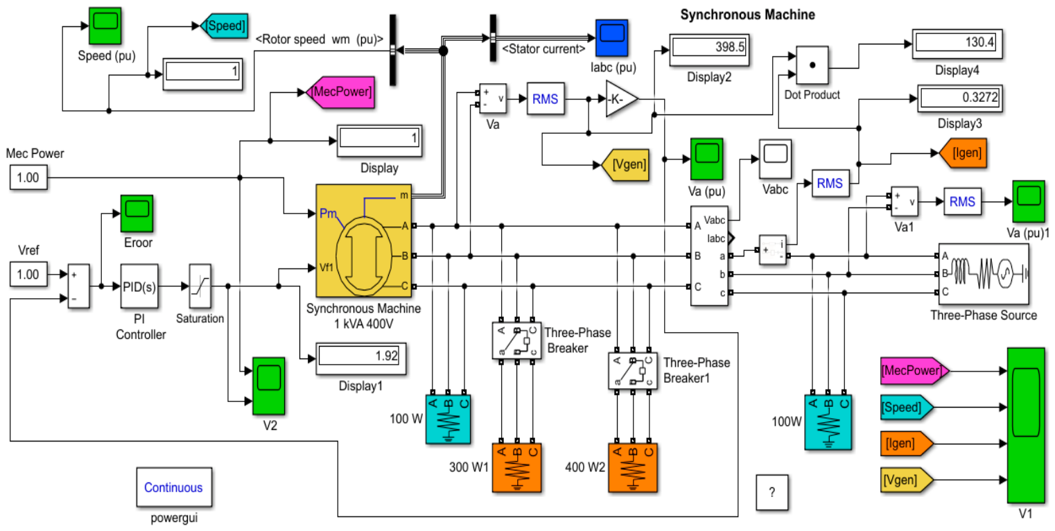
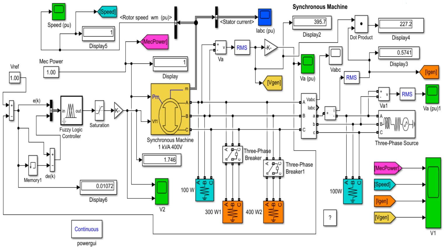
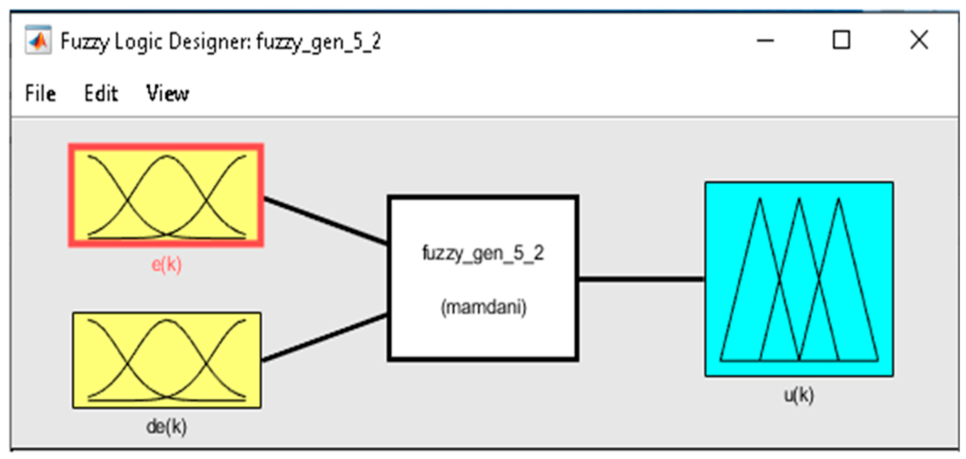
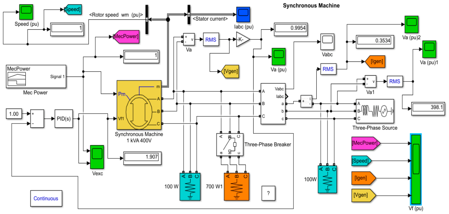
Figure 1 presents a block diagram of the model developed by the author in MATLAB-Simulink for a voltage regulation system for a three-phase synchronous generator operating under variable load and driven by a primary motor with constant power. The main blocks used in the structure of this model are as follows: (a) The three-phase synchronous generator. (b) The voltage regulator is of type PI and has an amplification factor kp = 120 and integration constant ki = 15. (c) There is a measuring block for voltage and current values at the output terminals of the three-phase synchronous generator. (d) Load resistors connected to the output terminals of the three-phase synchronous generator have active power rates of P1 = 100 W, P2 = 300 W, P3 = 400 W, and P4 = 100 W. (e) A three-phase connecting block allows the connection of a load resistor of 300 W after a time interval of 3 s; three-phase connection block 1 allows the connection of a load resistor of 400 W after a time interval of 5 s. These three-phase connection blocks are set with timing upon actuation. The variable load connected to the terminals of the three-phase synchronous generator will increase after a time of 3 s with the power rate of 300 W, to which a load of 400 W will be added 5 s later. (f) The RMS blocks allow the calculation of the average square values of the line voltage and current for a phase of the three-phase synchronous generator. The rotor of the three-phase synchronous generator is driven by a primary motor that has a power equal to the power of the three-phase synchronous generator. In this model, the values used are expressed in relative units. (g) The block for three-phase mains alternative current (A.C.) supply has the voltage U = 400 V and frequency f = 50 Hz. The oscilloscope V1 displays variation in the following signals: MecPower, power variation in the primary motor that drives the three-phase synchronous generator rotor. The mechanical power is expressed in relative units, (p.u.). Speed (p.u.), rpm variation in the three-phase synchronous generator; Igen (A), current variation through a phase winding of the three-phase synchronous generator; and Vgen (V), line voltage at the output terminals of the three-phase synchronous generator. The oscilloscope V2 displays the voltage variation in the excitation coil of the three-phase synchronous generator and the variation in the primary motor power that drives the generator rotor. Figure 2 shows a block diagram of the model developed by the author in MATLAB-Simulink of a regulation system for the voltage of a three-phase synchronous generator with a fuzzy logic controller running with variable load and driven by a primary motor with constant power. In principle, the blocks used in this structure are identical to the blocks used in the structure of the model presented in Figure 1. In this model, the fuzzy logic controller has been added. The structure of the fuzzy logic controller is presented in Figure 3.

2.1.3. Designing the Fuzzy Logic Controller FL

To design the fuzzy logic controller, the following input variables were chosen: the error e ( k ) and error derivate d e ( k ) and the output variable u ( k ) . The error signal ε ( k ) can be calculated through the following relation:
ε ( k ) =   V r e f   V a
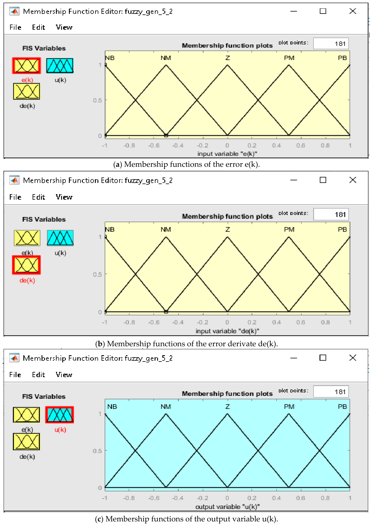
where V r e f = 1 , and V a is the measured voltage between two phases. This value is divided by 400 so that the measured voltage applied to the summing block takes values in the range (0–1). For this type of controller, it is not necessary to determine the mathematical model of the fixed part. The output variable is determined as a function of the input variables based on functions defined in a rule base using membership functions. The ranges of variation in the input variables and the output variable are within the interval [−1, 1]. The membership functions for each variable are shown in Figure 4 and are of the triangular type.
The rule base is presented in Table 1.
To write the rules, the following operators were used: if and then; NB, negative big; NS, negative small; Z, zero; PS, positive small; and PB, positive big. Below are two examples of rules from the total of 25 rules used by the fuzzy logic controller.
  • if (e(k) is NB) and (de(k) is NB) then (u(k) is PB);
  • if (e(k) is NS) and (de(k) is Z) then (u(k) is PS).
The inference method used in this case is the max-min method [26]:
μ U i ( u ) = m i n ( μ C i ( E i ) ,   μ O i ( u ) ) ; μ U ( u ) = m a x [ μ U i ( u ) ]
where μ C i ( E i ) = m i n ( μ A i ( E ) ,   μ B i ( E ) ) , and μ O i ( u ) is the function imposed through the rule R i . The de-fuzzying method used is the gravity center method, where the abscissa of the gravity center is determined with the following relation [26]:
U *   =   1 1 u μ U ( u ) d u 1 1 μ U ( u ) d u
The output variable u ( k ) is determined by means of relation (9).

2.1.4. Model of the Voltage Regulation System for the Three-Phase Synchronous Genera Tor Operating with Constant Load and Variable Frequency

Figure 5 presents a block diagram of the model developed by the author in MATLAB-Simulink for the voltage regulation system of a three-phase synchronous generator operating with a constant load and variable frequency.
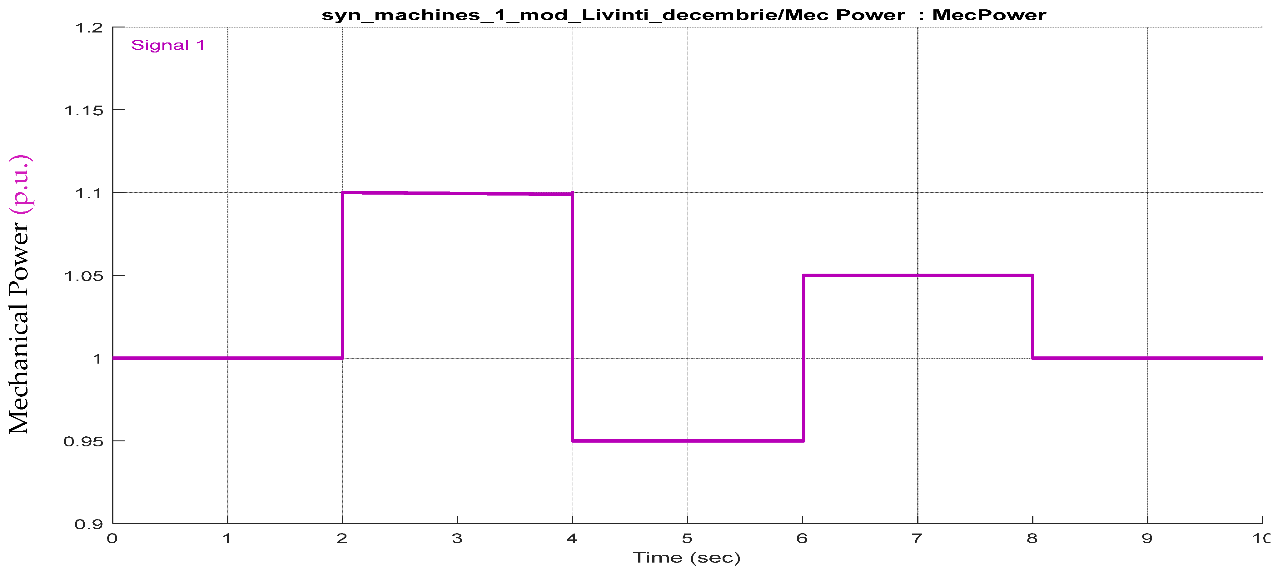
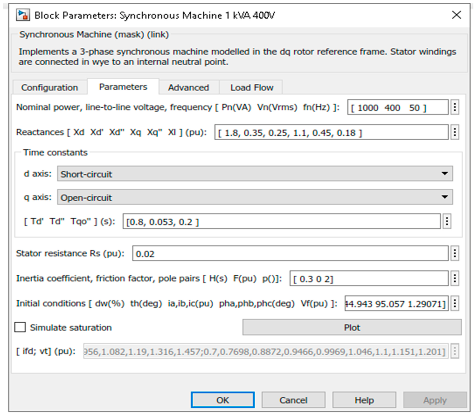
The MecPower block in this model generates a signal of variable power. The power variation in the primary motor that drives the rotor in the three-phase synchronous generator is presented in the diagram in Figure 6, which was conceived by the author and may resemble the power variation in a wind turbine caused by modifications to wind speed driving the rotor of the three-phase synchronous generator within the structure of a wind power station. In this model, a variable load of 700 W is connected to the terminals of the three-phase synchronous generator by means of a three-phase connection block after a time interval of 5 s. The three-phase connecting block is set with actuation delay. For all the models presented above, the parameters of the three-phase synchronous generator remain unchanged and are presented in Figure 7.

2.1.5. Functioning of the Models Created in MATLAB-Simulink

The rotor of the three-phase synchronous generator is driven by a primary motor with constant power in the first two models and one of variable power in the third model. The voltage rates at the output terminals of the three-phase synchronous generator are adjusted using a PI regulator that controls the supply voltage of the excitation coil of the three-phase synchronous generator for the first model and using a fuzzy logic controller for the second model. The reference rate for the adjustment loop of the excitation coil voltage will be equal to the unit because the models have been designed to run with relative values. The line voltage on the output terminals of the three-phase synchronous generator is measured. For this purpose, the RMS block is used, in order to calculate the average square value of the line voltage. The resulting value for the RMS block output will be divided by 400 in the amplifier block to obtain a unitary value. This voltage will represent the reaction size within the excitation voltage regulation loop of the three-phase synchronous generator. For the first two models, the PI controller or the fuzzy logic controller will provide a constant voltage at the terminals of the three-phase synchronous generator during operation with a variable load and constant frequency. The PI controller in the third model will provide a constant voltage at the output terminals of the three-phase synchronous generator during operation with a constant load and variable frequency. In these voltage regulation systems we have not implemented the vector control. The vector control can be implemented if the synchronous machine is powered from static frequency convertors.

2.2. Results of Simulations

2.2.1. Results of Simulations During Operation of the Three-Phase Synchronous Generator with a Variable Load and Constant Frequency

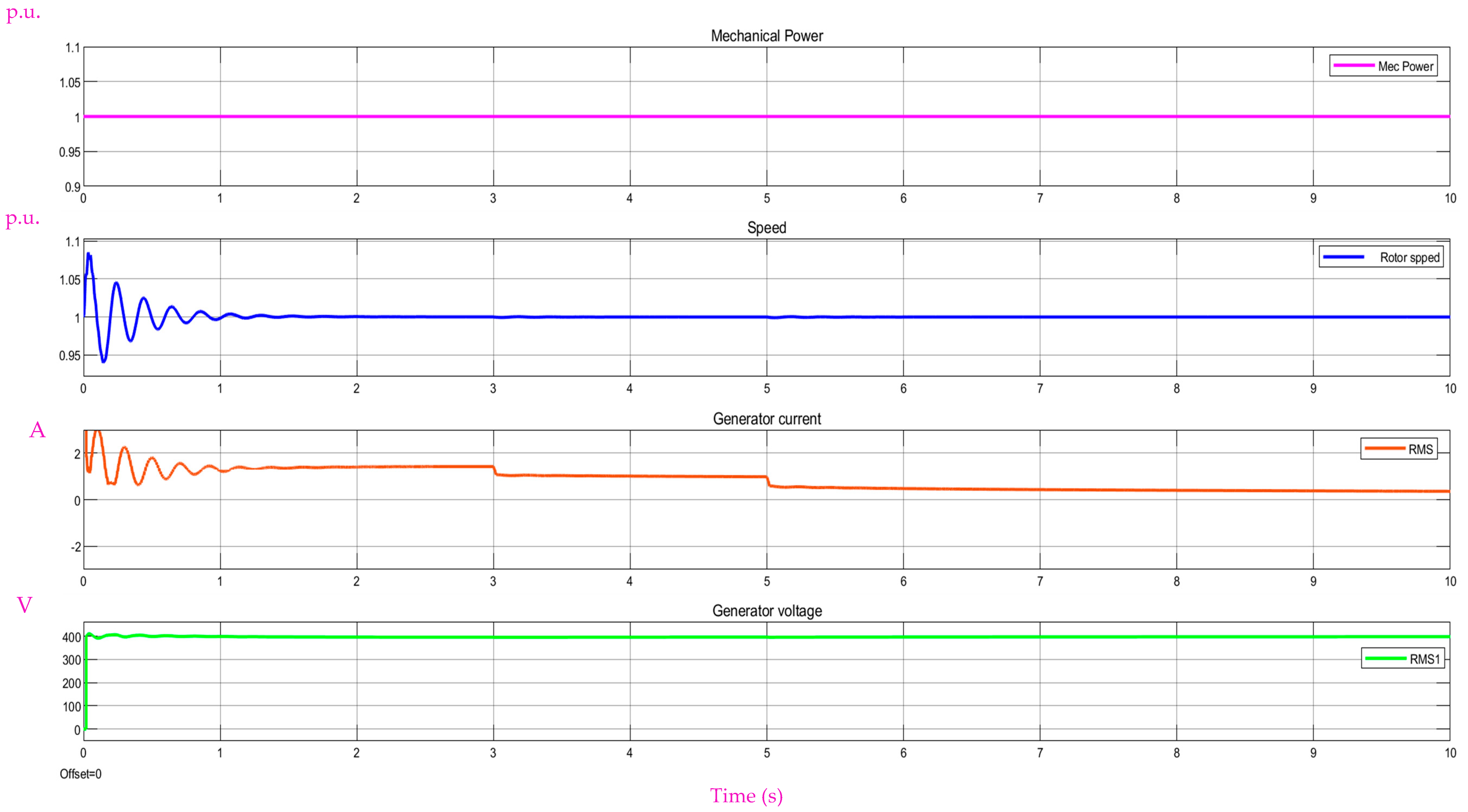
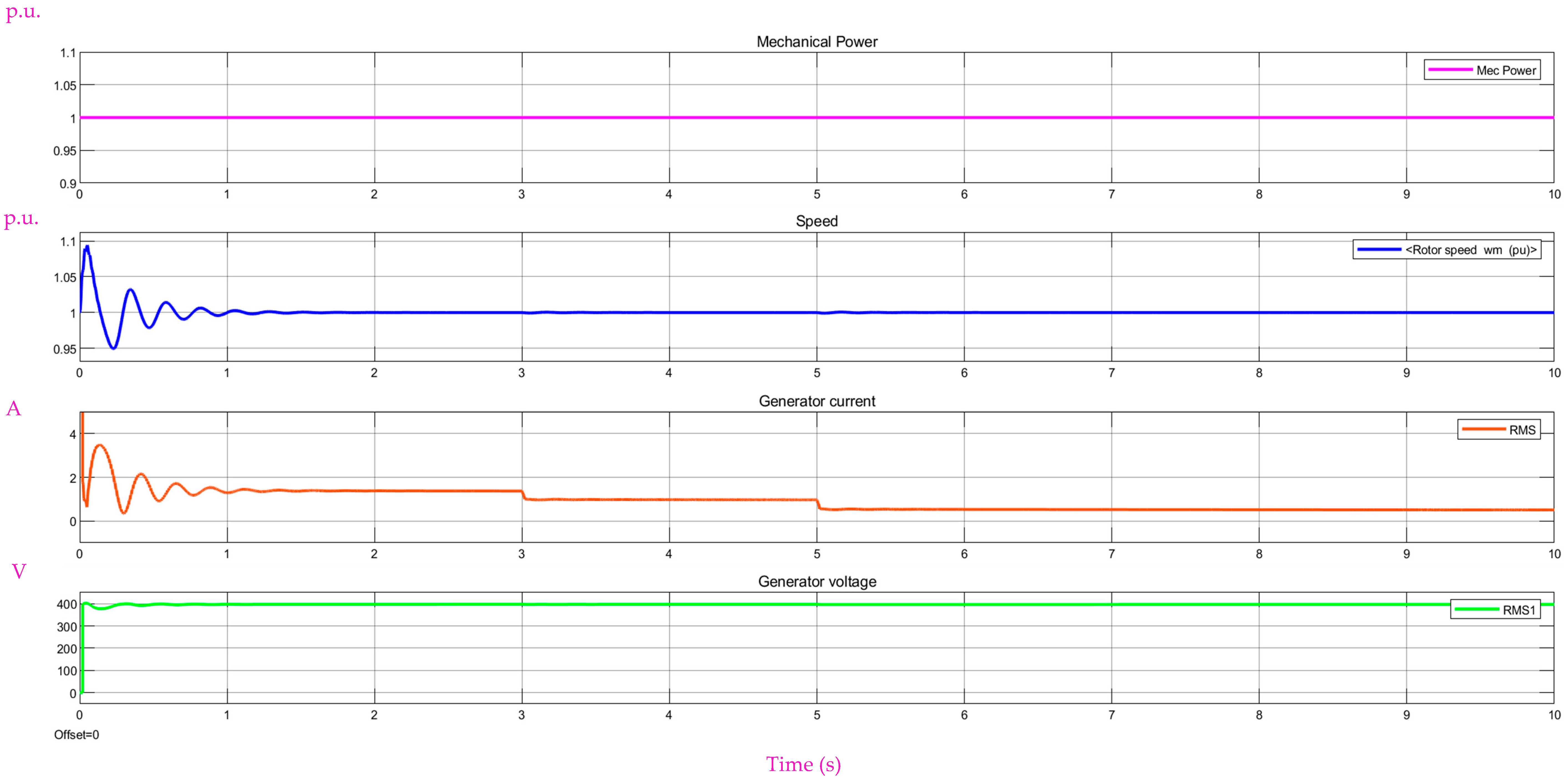
The current intensity variation through the phase winding of the synchronous generator while running with a variable load and constant frequency is shown in Figure 8 for model 1 and Figure 9 for model 2. The current intensity through the phase winding of the three-phase synchronous generator will decrease along with the increase in load connected to the output terminals of the generator. The voltage at the output terminals of the three-phase synchronous generator is kept constant due to the increased voltage supplied to the excitation coil.

2.2.2. Comparative Analysis of the Simulation Results for the First Two Models

For the first two models, the phase current intensity (display 3) is read, as well as the voltage between two phases (display 2) and the apparent power at the output of the three-phase synchronous generator (display 4), every two seconds, from the beginning of the simulations over its performance time of 10 s. By pushing the Run button on the control bar of each model, we insert a pause for reading the measurement instruments, and, after pushing the button again, the simulation is resumed. The values of the parameters are as follows and are presented in Table 2: phase current intensity, I g e n _ P I ; voltage between two phases, U g e n _ P I , S g e n _ P I , for model 1 and phase current intensity I g e n _ F L ; and voltage between phases, U g e n _ F L , S g e n _ F L , for model 2, obtained as a function of the time variation from the starting time of the simulation programs. The apparent power at the output terminals of the three-phase generator is given by the following relation:
S = U · I   ( V A )
From the results analysis shown in Table 2 and the variation diagrams of the parameters presented in Figure 8 and Figure 9, we can conclude the following: the current intensity through the phase winding of the three-phase synchronous generator decreases along with the increase in the load connected to the terminals of the three-phase synchronous generator. The current intensity through the phase winding of the three-phase synchronous generator is higher in the case of the automatic system for voltage adjustment equipped with a fuzzy logic controller (at the moment, la t = 6 s I g e n P I = 0.397 A and I g e n _ F L = 0.583 (A)). The voltage at the terminals of the three-phase synchronous generator remains constant. The apparent power of the three-phase generator output has a higher value when using the automatic system for voltage adjustment equipped with a fuzzy logic controller. As such, in this case, the electrical energy supplied by the three-phase synchronous generator will be higher than that supplied using the automatic system for voltage adjustment equipped with a PI controller (at the moment, t = 6 s S g e n _ P I = 158.2 (VA) and S g e n _ F L = 230.7 (VA)).

2.2.3. Results of Simulations Running the Three-Phase Synchronous Generator with a Constant Load and Variable Frequency

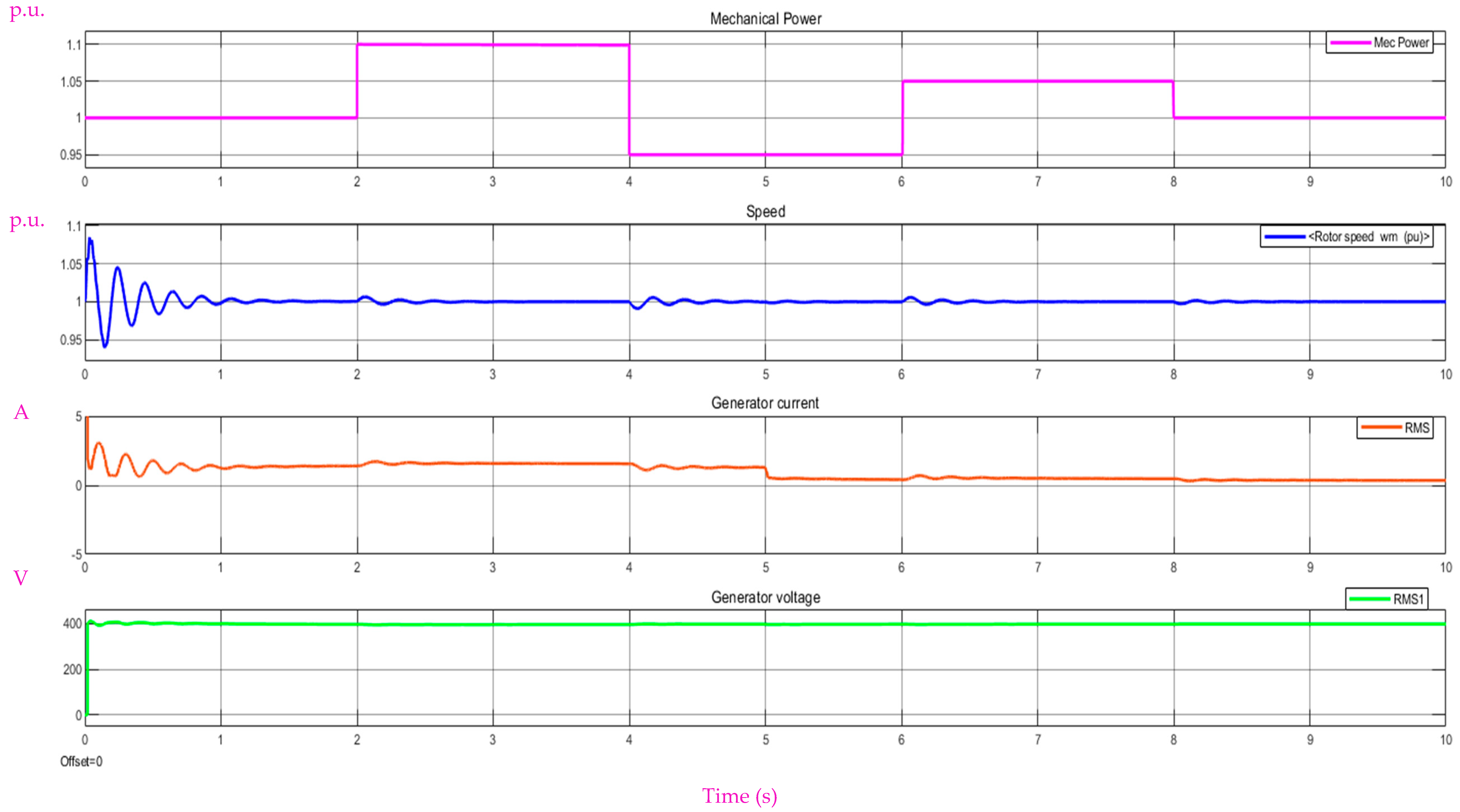
The current variation through the phase winding of the synchronous generator when the generator rotor is driven by a primary motor with variable power is shown in Figure 10.
Figure 10 shows that the rotor of the three-phase synchronous generator is driven by the primary motor with a variable power as a function of time. The current intensity through the phase winding of the three-phase synchronous generator will increase along with an increase in the primary motor power. With an increase in primary motor power from 1 to 1.1 in relative units, the current intensity through the phase winding of the generator will increase from 1.9 A to 2 A. The voltage value at the output terminals of the three-phase synchronous generator will be kept constant but will increase with an increase in supply voltage to the excitation winding. During the time interval from 4 s to 5 s, the power of the motor driving the rotor of the synchronous generator decreases from 1.1 to 0.95 in relative units. The current intensity decreases from 2 A to 1.85 A, and the voltage of the excitation winding will decrease. After 5 s, a load of 700 W is connected to the output terminals of the three-phase synchronous generator. The current intensity through the phase winding will decrease from 1.85 A to 0.7 A. As the load increases, the excitation winding voltage will increase. Finally, it can be seen that when the power of the motor driving the rotor of the synchronous generator changes, the excitation winding voltage also changes.

2.2.4. Comparative Analysis of PI and FL Controller Performance When Used in the Construction of the AVR (Automatic Voltage Adjustment) System with Controller Performance Presented in Other Works

Figure 8 shows that the maximum value of the voltage is equal to 410 V A.C. The value of the overshoot for the measured voltage at the output terminals of the synchronous generator is given by the following relation:
σ 1 = U m a x U r e f U r e f   . 100 % =   410 400 400 . 100 = 25 %
Figure 9 shows that the maximum value of the voltage is equal to 406 V A.C. The overshoot value is given by the following relation:
σ 2 = U m a x U r e f U r e f   . 100 % =   406 400 400 . 100 = 15 %
In Ref. [27], a comparative study is presented in which the parameters of a PID controller used for voltage control in an AVR system are tuned using the Particle Swarm Optimization (PSO) and Symbiotic Organism Search (SOS) algorithms. According to Ref. [27], the overshoot value determined using the Integral of Absolute Error (IAE) objective function is 22.45% for the SOS algorithm (Table 2 from Ref. [27]) and 21.12% for the PSO algorithm (Table 3 from Ref. [27]). Therefore, it can be observed that the voltage overshoot of the synchronous generator obtained with the AVR system employing the FL controller in this paper (15%) is lower than the values reported in Ref. [27] for the Integral of Absolute Error (IAE) objective function.

3. Experimental Results

3.1. Description of the Experimental Stand

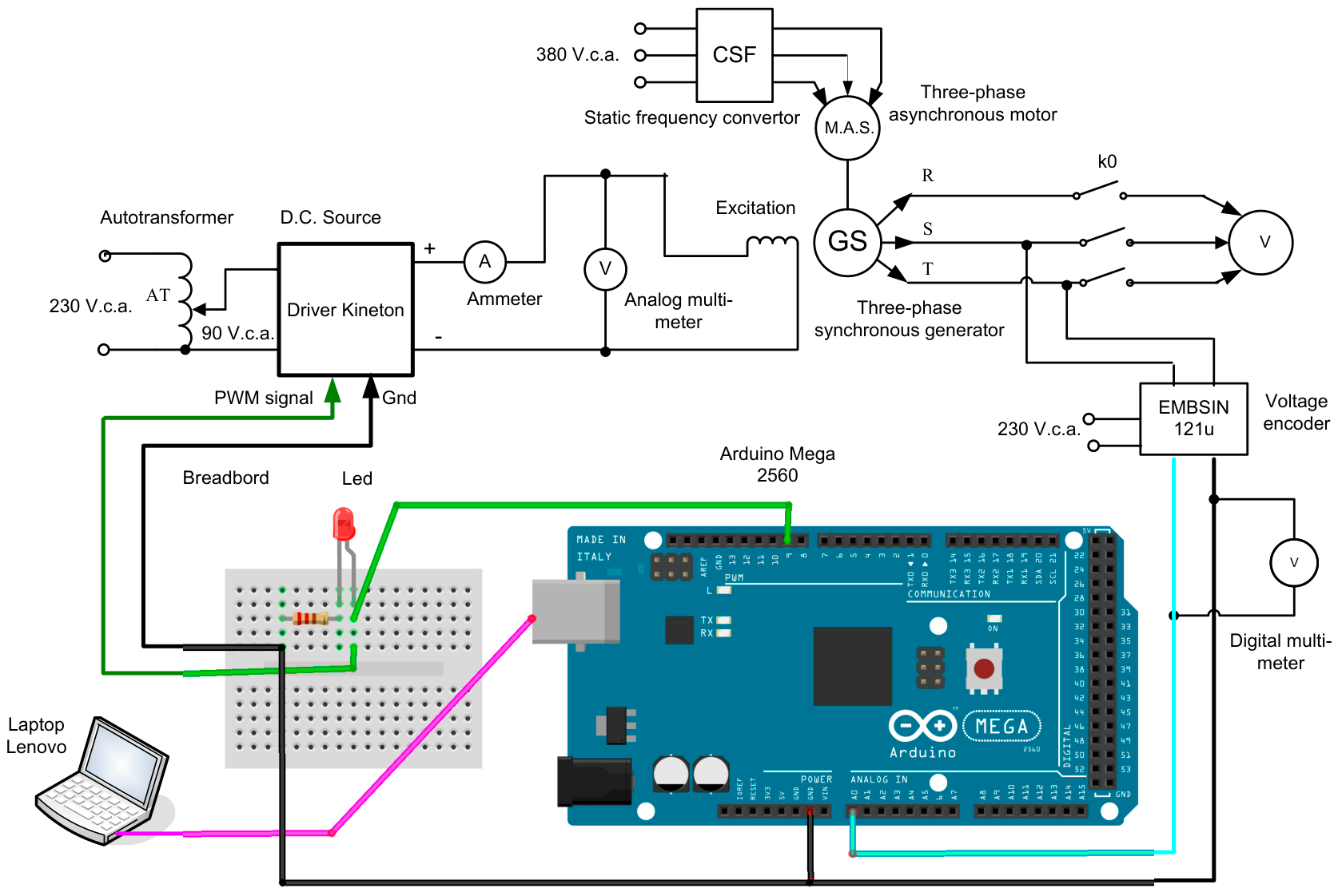
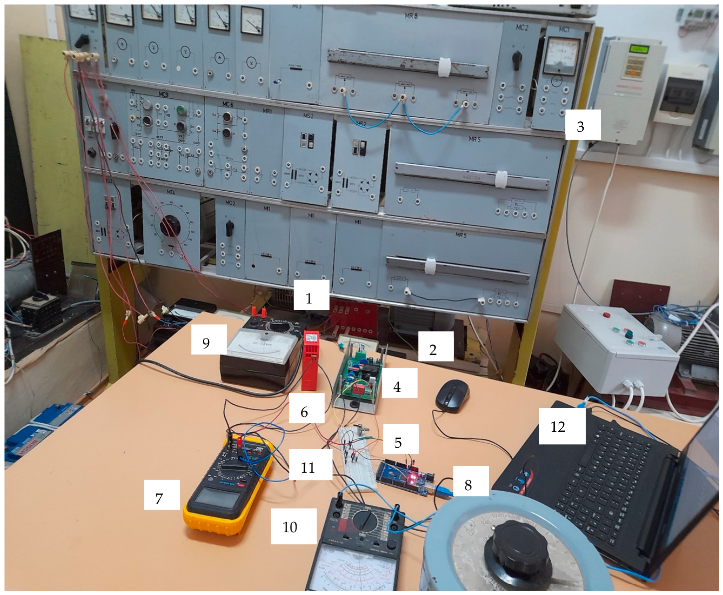
The electrical diagram of the experimental stand of the automatic voltage regulation system for the three-phase synchronous generator with electromagnetic excitation is presented in Figure 11. The voltage regulation system is implemented using the EMBSIN 121u voltage encoder (MBS Sulzbach Messwandler GmbH, Sulzbach-Laufen, Germany). This encoder has an accuracy class of 0.5. The signal from the encoder output is applied directly to an analog/digital input channel of the Arduino Mega 2560 development board (Arduino company, Ivrea, Italy). In Ref. [4], to build a real model of the AVR system (Figure 2 in Ref. [4]), a filtering circuit is inserted for the signal received from the voltage encoder. In the case of this encoder, there is no need for a filtering circuit for the output signal. A picture of the experimental stand is presented in Figure 12. The components of the experimental stand are as follows: (1) a three-phase synchronous generator; (2) a three-phase asynchronous motor; (3) a static frequency convertor; (4) a D.C. source, controlled through a PWM signal; (5) an Arduino Mega 2560 development board; (6) an EMBSIN 121u voltage encoder; (7) a digital multi-meter; (8) an autotransformer; (9) a MAVO 35 measuring instrument; (10) an analogic multi-meter; (11) a breadboard; (12) a Lenovo laptop.
The characteristics of the components are as follows: (1) The catalog rated data of the three-phase synchronous generator are rate power, P n = 1 KW; output rated voltage = U o u t = 400 V.A.C.; rated supply voltage of the excitation coil U e x c = 110 V.D.C.; and rated rpm n n = 1500 rev/min. (2) For the three-phase asynchronous motor with a short-circuit rotor, the catalog rated data are rate power, P n = 1.5 KW; rated supply voltage = U o u t = 400 V.A.C.; and rated rpm n n = 1500 rev/min. (3) The frequency static convertor is of the LG type with rated power Pn = 5.5 kW, supply voltage = 380 V A.C., and variable output voltage within the interval (0 ÷ 380) V.A.C., which is needed for supplying the three-phase asynchronous motor; the frequency of the variable output voltage is variable within the interval (0 ÷ 50) (Hz). (4) The voltage source is supplied as alternative current at 100 V from the autotransformer and generates a continuous variable voltage (0 ÷ 100) V at the output to supply the excitation coil. (5) The Arduino Mega 2560 development board is equipped with the micro controller ATmega 2560 and has 16 input analog/digital channels and 54 digital channels that can be used as input or outputs. On 14 pins, PWM signals can be obtained on the output. (6) The EMBSIN-121u voltage encoder is supplied at an A.C. voltage ranging within (0 ÷ 230) V.A.C. At the input, the variable voltage signal in the interval (0 ÷ 500) V.A.C. is applied, and, at the output, the resulting voltage signal will be within (1 ÷ 5) V.D.C. (7) The digital measuring instrument measures the voltage supplied by the voltage encoder EMBSIN −121u. (8) The autotransformer is supplied at a voltage of 230 V.A.C. and supplies a variable output voltage (0 ÷ 230) V.A.C. (9) The analog multi-meter is used to measure the supply voltage of the D.C. source mentioned at position 4. (10) The MAVO-35 multi-meter measures the supply voltage of the excitation coil in the three-phase synchronous generator. (11) The breadboard is used to provide connections between the Arduino Mega 2560 development board and the voltage source that supplies the excitation coil. (12) The laptop is used to program the Arduino Mega 2560 development board.

3.2. Experimental Determinations

The program for implementing the PID-type voltage regulator was developed by the author in the programming environment Arduino IDE. Through this program, the reference value of the line voltage of the three-phase synchronous generator is set at 400 VA.C. This value will be compared to the value of the voltage measured by the EMBSIN—121u voltage encoder for two phases at the output of the three-phase synchronous generator. The error signal is processed by the PID voltage regulator. The adjustment law of the PID regulator is given by the following relation:
u ( t ) =   k a e ( t ) +   k i e ( t ) d t   + k d d e ( t ) d t
where e ( t ) is the measuring error, determined via the following relation:
e ( t ) =   U r e f U m a s
where U r e f is the reference voltage and U m a s is the measured voltage rate.
-
u ( t ) is the output voltage of the regulator;
-
k a —amplification factor, k i —integration factor, k d —derivation factor.
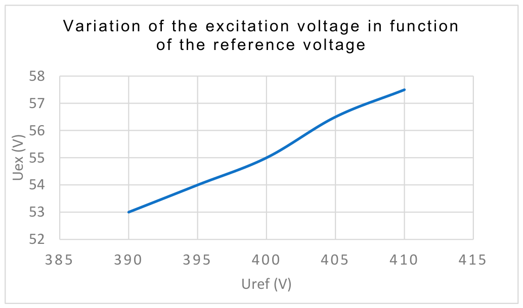
The parameters of the PID regulator have the following values: k a = 0.6 , k i =   1.4 , k d = 0.01 . The output signal of the voltage regulator is the PWM control signal for the supply voltage source of the excitation coil of the three-phase synchronous generator. The operation of the three-phase synchronous generator is analyzed in two cases. (a) The rpm of the rotor of the three-phase synchronous generator is kept constant, and the reference value of the line voltage is modified. With an increase in the reference voltage from 400 V A.C. to the value of 410 VA.C., the supply voltage of the excitation coil will increase from 55 V D.C. to 57.5 V.D.C. and the voltage of the synchronous generator will increase from 399.68 VA.C. to 409.43 VA.C. With a decrease in the reference voltage value from 400 V A.C. to 390 V A.C., the supply voltage of the excitation coil will decrease from 55 V D.C. to 53 V D.C. and the voltage at the terminals of the three-phase synchronous generator will decrease from 399.68 V A.C. to 389.65 V A.C. The results of the measurements are presented in Table 3 below.
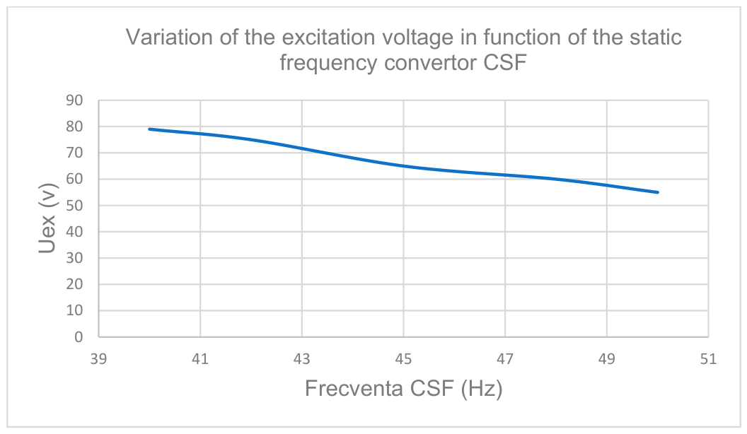
(b) The value of the reference line voltage is kept constant, and the rpm of the three-phase asynchronous generator is modified. The rpm of the generator rotor is modified through variation in the voltage frequency at the output of the static frequency convertor that supplies the three-phase asynchronous motor. With an increase in the frequency of the supply voltage of the three-phase asynchronous motor, the rpm of the rotor of the three-phase synchronous generator will increase, and this will lead to an increase in synchronous generator voltage. In this case, the voltage regulator will lower the supply voltage of the excitation coil. With a decrease in the frequency of the supply voltage of the three-phase asynchronous motor, the rpm of the synchronous generator rotor will decrease, leading to a decrease in the voltage of the three-phase synchronous generator. In this case, the voltage regulator will increase the supply voltage of the excitation coil. In conclusion, with the modification of the rotor rpm, the voltage of the three-phase synchronous generator remains constant throughout the variation in the supply voltage of the excitation coil. The results of the measurements are listed in Table 4 below.
With an increase in the frequency of the supply voltage of the three-phase asynchronous motor from 40 Hz to 50 Hz, the value of the excitation coil voltage will decrease from 79 V D.C. to 55 V D.C. and the voltage at the output terminals of the generator will remain constant. In Figure 13, the variation in the excitation voltage is presented as a function of the variation in the reference line voltage. Figure 14 presents the variation in the excitation voltage as a function of the frequency variation in the supply voltage of the three-phase asynchronous motor.

4. Conclusions

This work presents a study on adjusting the voltage rate at the output terminals of a three-phase synchronous generator using the EMBSIN 121 voltage encoder. The purpose of this study was to enhance the quantity and quality of the electrical energy produced by a three-phase synchronous generator. We achieved this both through simulations and an experimental stand developed in the Electrical Machines and Drives laboratory of the Engineering Faculty in Bacau. This work is innovative because the author developed three models in MATLAB-Simulink to study voltage adjustment in a three-phase synchronous generator with electromagnetic excitation in two distinct cases: case 1, running the three-phase asynchronous generator with a variable load and constant frequency, and case 2, running the three-phase asynchronous generator with a constant load and variable frequency. In the first case, the voltage is adjusted through an automatic voltage adjustment system equipped with a proportional integrative (PI) controller or through a fuzzy logic (FL) controller. The voltage is adjusted in the second case through an automatic voltage adjustment system equipped with a PI controller. In the case of the automatic voltage adjustment system with a fuzzy logic controller, the electrical energy supplied by the three-phase synchronous generator will be higher than that using a PI controller (at the moment, t = 6 s S g e n _ P I = 158.2 (VA) and S g e n _ F L = 230.7 (VA)). A comparative analysis of the performance of the PI and FL controllers used in the AVR system against the controllers presented in Ref. [27] shows that a lower voltage overshoot is achieved with the AVR system employing the FL controller proposed in this paper. For the PI controller, the voltage overshoot is σ 1 = 25 % , whereas for the FL controller, it is σ 2 = 15 % . To implement the algorithm for adjusting the voltage of the three-phase synchronous generator with the help of the EMBSIN 121u voltage encoder, the author also created a program in the programming environment Arduino IDE. The experimental results demonstrate that the voltage at the output terminals of the three-phase synchronous generator remains constant when the reference voltage value is changed, as well as when the frequency of the supply voltage of the three-phase asynchronous motor that drives the rotor of the three-phase synchronous generator is changed via modifications to the supply voltage of the excitation winding of the three-phase synchronous generator. The voltage encoder EMBSIN 121u has an accuracy class equal to 0.5, and the voltage signal supplied by the encoder can be directly connected to an analog/digital channel of the Arduino Mega 2560 development board. This study could be used for three-phase synchronous generators with electromagnetic excitation used to construct wind power stations.

Funding

This paper is financed by the University “Vasile Alecsandri” of Bacau from the funds allocated for research.

Data Availability Statement

The original contributions presented in this study are included in the article; further inquiries can be directed to the corresponding author.

Conflicts of Interest

The author declares no conflicts of interest.

References

  1. Obeidat, F. Three Phase Synchronous Machine. Philadelphia University. Available online: https://www.philadelphia.edu.jo/academics/fobeidat/uploads/Electric%20machines%20I/5%20AC%20machimes-synchronous%20machine.pdf (accessed on 1 February 2026).
  2. Synchronous Generators I. Available online: http://www.egr.unlv.edu/~eebag/Synchronous%20Generator%20I.pdf (accessed on 18 January 2026).
  3. Vamsi, K.; Sarath Chandra, B. A Voltage Regulator for Parallel Operated Isolated Synchronous Generators Using Statcom. Int. J. Eng. Res. Technol. (IJERT) 2013, 1, 7–11. [Google Scholar]
  4. Heshamo, H.; Ezzat, M.; Swief, R.A. Comparative study of PID controller designs for AVR using different optimization techniques. Arch. Electr. Eng. 2021, 70, 567–583. [Google Scholar] [CrossRef]
  5. Rais, M.C.; Dekhandji, F.Z.; Recioui, A.; Rechid, M.S.; Djedi, L. Comparative Study of Optimization Techniques Based PID Tuning for Automatic Voltage Regulator System. Eng. Proc. 2022, 14, 21. [Google Scholar] [CrossRef]
  6. Tarnapowicz, D.; Zaleski, T.; Matuszak, Z.; Jaskiewicz, M.; Sawicki, S. Testing the Automatic Voltage Regulators of Ship Synchronous Generators Using Hardware-in-the-Loop Technology. Energies 2024, 17, 5963. [Google Scholar] [CrossRef]
  7. Hussein, M.M.; Senjyu, T.; Orabi, M.; Wahab, M.A.A.; Hamada, M.M. Control of a Stand-Alone Variable Speed Wind Energy Supply System. Appl. Sci. 2013, 3, 437–456. [Google Scholar] [CrossRef]
  8. Sahu, S.; Panda, G.; Yadav, S.P. Dynamic Modelling and Control of PMSG based Stand-alone Wind Energy Conversion System. In Proceedings of the 2018 Recent Advances on Engineering, Technology and Computational Sciences (RAETCS), Allahabad, India, 6–8 February 2018. [Google Scholar] [CrossRef]
  9. Yegireddy, N.K.; Panda, S.; Tentu, P.; Durgamalleswarao, K. Comparative analysis of PID controller for an Automatic Voltage Regulator system. In Proceedings of the Conference: 2015 International Conference on Electrical, Electronics, Signals, Communication and Optimization (EESCO), Visakhapatnam, India, 24–25 January 2015. [Google Scholar] [CrossRef]
  10. Coelho, L.D.S. Tuning of PID controller for an automatic regulator voltage system using chaotic optimization approach. Chaos Solitons Fractals 2009, 39, 1504–1514. [Google Scholar] [CrossRef]
  11. Sankhwar, P. Excitation System, Proportional and Integral Controls of a Synchronous Generator for Reducing Adverse Impacts to Power System from Voltage Fluctuations. Int. J. Electr. Power Syst. Technol. 2025, 11, 1–17. [Google Scholar]
  12. Tarnapowicz, D.; German-Galkin, S.; Staude, M. Investigation Concerning the Excitation Loss of Synchronous Generators in a Stand-Alone Ship Power Plant. Energies 2021, 14, 2828. [Google Scholar] [CrossRef]
  13. Abdelrazek, M.; Awad, H.; El-kholy, E.E. An Experimental Investigation of a Self-Excited Synchronous Generator: Loading Characteristics and Output Voltage Harmonics. In Proceedings of the 2017 Nineteenth International Middle East Power Systems Conference (MEPCON), Cairo, Egypt, 19–21 December 2017. [Google Scholar] [CrossRef]
  14. Zhang, C.; Lv, X.; Pu, C. Voltage regulation control of three-stage synchronous generator based on modified differential evolution algorithm. J. Phys. Conf. Ser. 2024, 2917, 012024. [Google Scholar] [CrossRef]
  15. Bo, L.; Li, Y.R.; Xu, L.; Lu, J.L. Research on Voltage Regulator System of Aircraft Power Generation System. Adv. Mater. Res. 2012, 588–589, 552–557. [Google Scholar] [CrossRef]
  16. Luo, Y.; Zhang, C.; Li, S.; Duan, X.; Zhang, X.; Li, W. Modeling and Simulation of Three-stage Synchronous Generator and it’s Voltage Regulator for Aircraft. In Proceedings of the 2018 21st International Conference on Electrical Machines and Systems (ICEMS), Jeju, Republic of Korea, 7–10 October 2018; pp. 749–754. [Google Scholar]
  17. Chen, Z.; Zheng, R.; Ma, R.; Li, S.; Li, Y.; Cui, M.; Yang, Y. Comparison of PID Controllers with Engineering-Tuned Parameters and Fuzzy PID Controllers in the Application of Boost Converters. In Proceedings of the 2024 3rd International Conference on Energy, Power and Electrical Technology (ICEPET), Chengdu, China, 17–19 May 2024. [Google Scholar] [CrossRef]
  18. Ismail, N.F.N.; Hashim, N.; Baharom, R. A Comparative Study of Proportional Integral Derivative Controller and Fuzzy Logic Controller on DC/DC Buck-Boost Converter. In Proceedings of the 2011 IEEE Symposium on Industrial Electronics and Applications, Langkawi, Malaysia, 25–28 September 2011; pp. 149–154. [Google Scholar]
  19. Nethaji, G.; Kathirvelan, J. Performance comparison between PID and Fuzzy logic controllers for the hardware implementation of traditional high voltage DC-DC boost converter. Heliyon 2024, 10, e36750. [Google Scholar] [CrossRef]
  20. Livinti, P.; Culea, G.; Banu, I.V.; Vernica, S.G. Comparative Study of a Buck DC-DC Converter Controlled by the MPPT (P&O) Algorithm without or with Fuzzy Logic Controller. Appl. Sci. 2024, 14, 7628. [Google Scholar] [CrossRef]
  21. Byar, M.; Abounada, A.; Brahmi, A. A Performance comparison between PID and Fuzzy logic controllers for a DC-DC boost converter for photovoltaic applications. J. Electr. Syst. Autom. (JESA) 2022, 1, 1–8. [Google Scholar]
  22. Zharkov, M.A.; Sarakhanova, R.Y.; Salvasser, A.A.; Khoroshev, M.A. Synthesis of the Control System for the Voltage Stabilization Unit of theThree-Stage Synchronous Generator. In Proceedings of the Conference: 2021 XV International Scientific-Technical Conference on Actual Problems of Electronic Instrument Engineering (APEIE), Novosibirsk, Russian, 19–21 November 2021. [Google Scholar] [CrossRef]
  23. Fjärstedt, E. Implementation of an Automatic Voltage Regulator for Synchronous Machines on an FPGA. Master’s Thesis, Uppsala University, Uppsala, Sweden, 2019; pp. 1–40. [Google Scholar]
  24. Hamza, M. Design and Fabrication an Automatic Voltage Regulator for a Three Phase Synchronous Generator; University of Engineering and Technology Taxila: Taxila, Pakistan, 2018. [Google Scholar]
  25. Ezenugu, I.A.; Nwokonko, C.S. Automatic Voltage Regulator Control System for Synchronous Generator. Saudi J. Eng. Technol. 2024, 9, 265–273. [Google Scholar] [CrossRef]
  26. Sofron, E.; Bizon, N.; Ionita, S.; Raducu, R. Sisteme de Control Fuzzy—Modelare si Proiectare Asistate de Calculator. Editura All Educational Bucuresti, 1999. Available online: https://www.targulcartii.ro/emil-sofron/sisteme-de-control-fuzzy-all-1998-1927805 (accessed on 5 March 2026).
  27. Özgenç, B.; Ayas, M.Ş.; Altaş, İ.H. Optimally Tuned PID Controller Design for an AVR System: A Comparison Study. Int. J. Multidiscip. Stud. Innov. Technol. 2019, 3, 157–161. [Google Scholar]
Figure 1. Model in MATLAB Simulink for adjusting the voltage of a three-phase synchronous generator with a PI controller operating at a variable load and constant frequency.
Energies 19 03141 g001
Figure 2. Model in MATLAB Simulink for adjusting the voltage of a three-phase synchronous generator with a fuzzy logic controller operating at a variable load and constant frequency.
Energies 19 03141 g002
Figure 3. Structure of the fuzzy logic controller FL.
Energies 19 03141 g003
Figure 4. Membership functions of fuzzy logic variables.
Energies 19 03141 g004
Figure 5. Model in MATLAB Simulink for voltage adjustment in a three-phase synchronous generator driven by a primary motor with variable power.
Energies 19 03141 g005
Figure 6. Variation in the primary motor power that drives the rotor of the three-phase synchronous generator.
Energies 19 03141 g006
Figure 7. Parameters of the three-phase synchronous generator.
Energies 19 03141 g007
Figure 8. Current variation through the phase winding of the synchronous generator operating with a variable load and constant frequency for model 1.
Energies 19 03141 g008
Figure 9. Current variation through the phase winding of the synchronous generator operating with a variable load and constant frequency for model 2.
Energies 19 03141 g009
Figure 10. Current variation through the phase winding of the synchronous generator when the generator rotor is driven by a primary motor with variable power.
Energies 19 03141 g010
Figure 11. Electrical diagram of the experimental stand.
Energies 19 03141 g011
Figure 12. Picture of the experimental stand.
Energies 19 03141 g012
Figure 13. Variation in the excitation voltage as a function of the variation in the reference line voltage.
Energies 19 03141 g013
Figure 14. Variation in the excitation voltage as a function of the frequency variation in the static frequency convertor (CSF).
Energies 19 03141 g014
Table 1. The rule base.
e(k)
NBNSZPSPB
de(k)NBPBPBPBPSZ
NSPBPBPSZNS
ZPBPSZNSNB
PSPSZNSNBNB
PBZNSNBNBNB
Table 2. Simulation results for running the three-phase synchronous generator with a variable load and constant frequency.
Time (s)
246810
Parameter
I g e n _ P I (A)1.4030.9530.3970.3420.327
U g e n _ P I (V)396.4397.1397.6398.3398.5
S g e n _ P I (VA)556.0387.7158.2136.4130.4
I g e n _ F L (A)1.3930.9970.5830.5770.574
U g e n _ F L (V)396.7396.3395.6395.7397.7
S g e n _ F L (VA)552.7395.3230.7228.7227.2
Table 3. The results of the measurements for case (a).
No. Uref
(V)
Ugen
(V)
Signal PWMUex
(V)
Iex
(A)
Uencod.
(V)
Error
e(t) (V)
1390389.65168530.363.990.35
2395394.90170540.374.030.10
3400399.68173550.384.070.32
4405404.5017556.50.394.090.50
5410409.4317857.50.3954.140.57
Table 4. The results of the measurements for case (b).
No.Frequency
CSF (Hz)
Ugen
(V)
Signal PWMUex
(V)
Iex
(A)
Uenc.
(V)
140399243790.514.06
242398225750.494.06
345399201650.424.07
448399182600.394.07
550400171550.364.08
Disclaimer/Publisher’s Note: The statements, opinions and data contained in all publications are solely those of the individual author(s) and contributor(s) and not of MDPI and/or the editor(s). MDPI and/or the editor(s) disclaim responsibility for any injury to people or property resulting from any ideas, methods, instructions or products referred to in the content.