1. Introduction
The rapid expansion of variable renewable energy sources such as wind and solar has intensified the need for efficient, scalable, and flexible energy storage technologies. Among the various options under investigation, hydrogen-based energy systems have emerged as a key enabler for long-duration storage and sector coupling, particularly in the context of deep decarbonization pathways [
1,
2,
3]. In such systems, electricity is converted into hydrogen via electrolysis, stored, and later reconverted into electricity using fuel cells [
4,
5]. While this approach offers high energy density and long storage durations, it typically relies on separate electrolyzer and fuel cell units, resulting in increased system complexity, cost, and footprint. In this context, proton-exchange-membrane reversible fuel cells (rPEM) represent a particularly attractive solution, as they integrate hydrogen production and electricity generation within a single electrochemical architecture [
6].
Unlike conventional systems, where electrolyzers and fuel cells are separate units, rPEM devices operate in dual mode, enabling direct switching between water electrolysis (WE) and fuel cell (FC) operation. This configuration reduces system complexity and improves compactness, making it especially suitable for distributed and stationary energy storage applications. This dual functionality offers significant advantages in terms of system compactness, reduced balance-of-plant requirements, and potentially lower capital costs compared to discrete systems [
7,
8]. Despite these advantages, PEM Unitized regenerative fuel cell (PEM-URFC) technology remains at a relatively low level of technological maturity compared to standalone PEM fuel cells and electrolyzers. While conventional PEM fuel cells have reached commercial deployment in automotive and stationary applications [
9], and PEM electrolyzers are being scaled to multi-megawatt installations [
10], URFC systems are largely confined to laboratory-scale demonstrations and small pilot systems, typically below 5–10 kW [
11,
12,
13]. This disparity highlights the presence of fundamental scientific and engineering challenges that are unique to reversible operation.
One of the primary challenges arises from the requirement for bifunctional electrodes, particularly at the oxygen electrode. In electrolysis mode, the oxygen evolution reaction (OER) dominates, requiring highly active and stable catalysts such as iridium oxide (IrO
2). In contrast, during fuel cell operation, the same electrode must efficiently catalyze the oxygen reduction reaction (ORR), which is typically optimized using platinum-based catalysts. These reactions not only differ in their kinetics but also in their optimal operating conditions, leading to intrinsic trade-offs in catalyst selection and electrode design [
14,
15,
16]. As a result, the performance of URFCs in each mode is often compromised relative to dedicated devices. In addition to materials challenges, transport phenomena in URFCs are inherently more complex than in conventional PEM systems. Water management, in particular, plays a dual and often conflicting role: electrolysis mode requires continuous water supply to the anode, while fuel cell mode generates water at the cathode, which must be effectively removed to prevent flooding. The porous transport layers and flow fields must therefore accommodate fundamentally different transport regimes within the same physical structure. Previous studies have highlighted the critical role of gas diffusion layers (GDLs) in managing these competing requirements, yet a universally optimized design has not been established [
17]. While these material and transport challenges are significant, an equally critical, but comparatively underdeveloped, area is the modelling of URFC systems. Modelling plays a central role in guiding design, optimizing performance, and enabling scale-up. For conventional PEM fuel cells and electrolyzers, a wide range of modelling approaches has been developed, spanning from fundamental electrochemical descriptions [
18,
19,
20,
21,
22,
23] to multi-dimensional computational fluid dynamics (CFD) simulations [
24,
25,
26,
27]. However, these models are typically formulated for a single mode of operation and are not directly transferable to reversible systems.
In the context of URFCs, existing models treat electrolysis and fuel cell operation as separate regimes, often requiring different parameter sets or even entirely different model formulations. This lack of a unified modelling framework limits the predictive capability of simulations, particularly when analyzing mode switching, transient behavior, or long-term degradation. Furthermore, key phenomena specific to reversible operation, such as the interaction between OER and ORR kinetics on bifunctional electrodes, or the dynamic redistribution of water and heat during mode transitions, are rarely captured in existing models. The limitations of current modelling approaches become even more pronounced when considering the scaling of URFC systems toward practical power levels, particularly in the range of ~100 kW. At this scale, additional challenges emerge, including flow distribution across large active areas, thermal management within stacks, mechanical stresses due to pressure and hydration cycling, and system-level integration with balance-of-plant components. While these issues have been extensively studied for standalone PEM fuel cells and electrolyzers [
28,
29,
30,
31,
32,
33] their manifestation in URFC systems remains poorly understood. A major barrier to progress in this area is the lack of validated experimental data at intermediate and large scales. Most published studies focus on single-cell performance or small stacks, with limited reporting on multi-kilowatt systems and virtually no publicly available data at the 100 kW level. This scarcity of data hampers both model validation and the development of reliable scaling laws.
Moreover, the increasing interest in integrating URFCs with renewable energy systems introduces additional requirements for dynamic and control-oriented modelling [
34,
35,
36]. Unlike steady-state operation, renewable-driven systems are characterized by fluctuating inputs, necessitating rapid switching between electrolysis and fuel cell modes. Capturing these dynamics requires models that are not only physically accurate but also computationally efficient, enabling their use in real-time control and optimization. Current modelling approaches, which are either overly simplified or computationally intensive, are not well suited to this task.
In light of these challenges, there is a clear need for modelling methodologies capable of linking electrochemical behavior to stack- and system-level design in reversible PEM fuel cell systems. Although previous studies have investigated electrochemical performance, catalyst development, and transport phenomena in PEM-URFCs, comparatively limited attention has been devoted to the integration of calibrated electrochemical models with large-scale system design and operational analysis, particularly in the 100 kW power range. Furthermore, the dynamic interaction between electrochemical, thermal, and fluidic subsystems under reversible operation remains insufficiently explored.
The present work addresses these limitations through the development of a calibrated electrochemical modelling framework integrated into a system-level design methodology for reversible PEM systems. The proposed approach combines polarization curve fitting, residual error analysis, and thermal modelling in order to provide a comprehensive evaluation of both cell-level and system-level performance. Particular attention is devoted to the consistency between electrochemical calibration and system sizing, highlighting how inaccuracies at the cell scale can propagate to stack and plant-level performance predictions. The methodology is subsequently applied to the design and analysis of a 100 kW reversible PEM system intended for hydrogen-based energy storage applications. The resulting framework enables the assessment of operating efficiency, thermal behavior, hydrogen management, and mode-switching implications under realistic operating conditions. In addition, the work investigates the impact of integrated hydrogen storage and reversible operation on system architecture, with emphasis on the trade-offs between compactness, efficiency, control complexity, and operational flexibility.
By combining electrochemical calibration with system-level analysis, this study aims to provide a scalable modelling approach for reversible PEM systems and to contribute to the understanding of the challenges associated with the transition from laboratory-scale devices to medium-scale energy storage applications.
3. Model Validation
The model parameters are calibrated against literature polarization data under representative operating conditions [
44]. The calibration procedure minimizes the deviation between simulated and experimental voltages over the entire current density range, ensuring accuracy in both low-load and high-load regimes.
The resulting parameter set is physically consistent and remains within literature-reported ranges, ensuring both accuracy and interpretability.
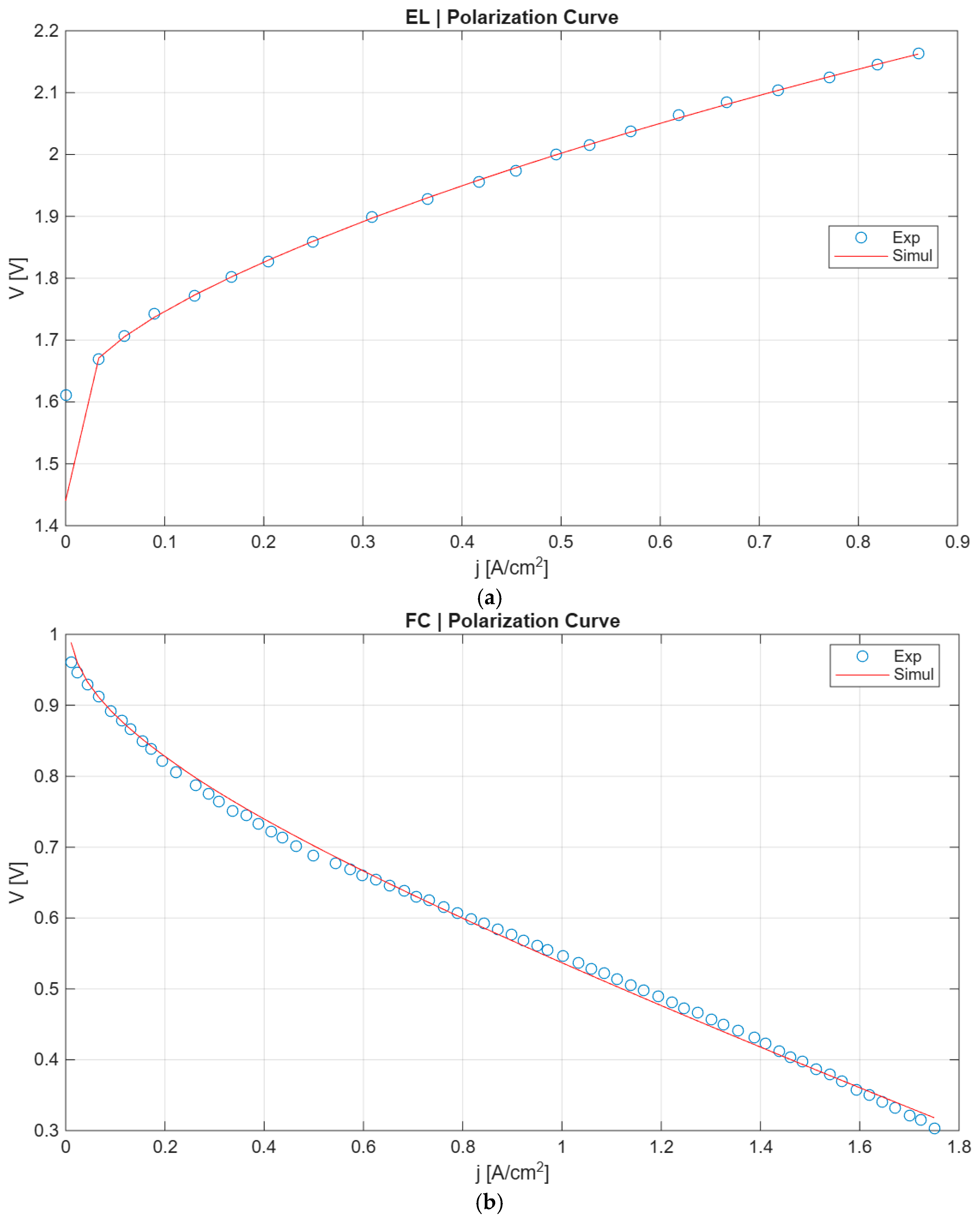
The calibrated model shows excellent agreement with experimental data in both operating modes. In fuel cell operation, the model accurately reproduces the voltage decrease with increasing current density, with particularly strong agreement in the medium-to-high current region, which is most relevant for practical applications. In electrolyzer mode, the model captures the expected monotonic increase in voltage, as well as the correct curvature of the polarization curve. The agreement is especially strong in the operating range above zero current density.
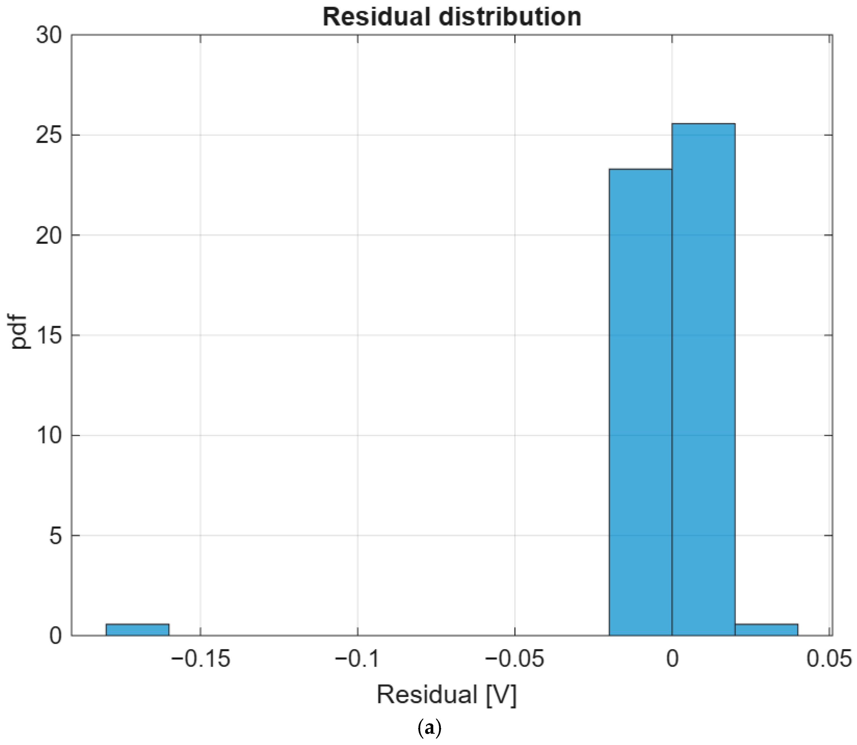
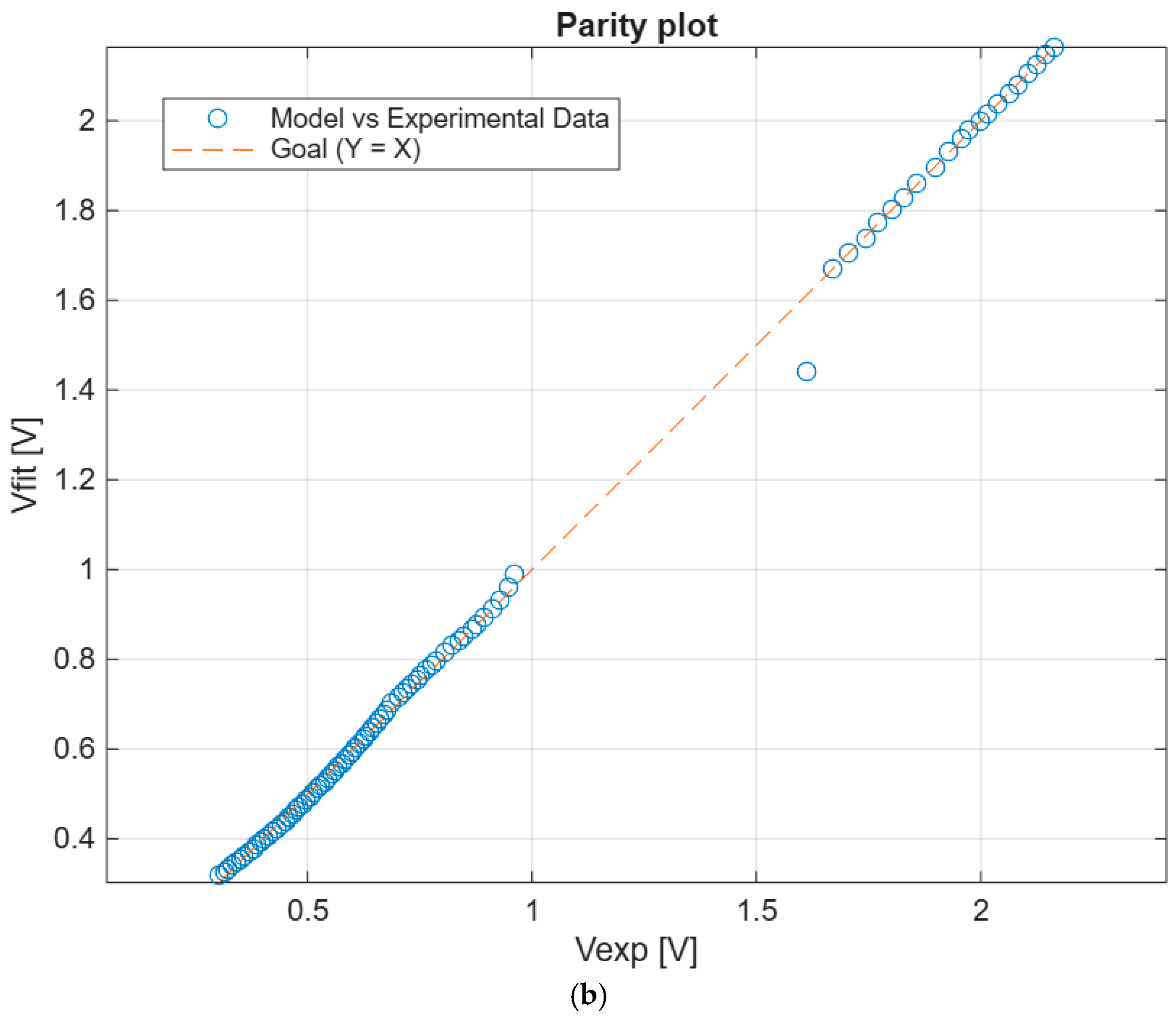
Residual analysis is shown in
Figure 1 and it is performed to assess model robustness and identify potential systematic deviations. The initial model exhibits clear trends, particularly in fuel cell mode, where errors increase with current density. These trends indicate structural inaccuracies in the model formulation. Following calibration, residuals are significantly reduced and become randomly distributed around zero. The residual range achieves values of ±0.02 V, demonstrating a substantial improvement in model accuracy. In electrolyzer mode, the calibrated model eliminates the negative bias observed in the initial formulation, maintaining residuals close to zero across the entire current range. This confirms that the calibration procedure effectively captures the underlying electrochemical behavior.
The residual distribution is strongly centered around zero, indicating the absence of systematic bias in the calibrated model. Most residuals are confined within a narrow band (approximately ±0.01–0.02 V), demonstrating high predictive accuracy. A limited number of outliers is observed, with one extreme negative deviation around −0.17 V, likely associated with low-current operating conditions where measurement uncertainty is higher. Overall, the distribution confirms that the calibration procedure effectively minimizes both mean error and variance. The parity plot shows excellent agreement between model predictions and experimental data, with most points lying along the identity line. The dispersion is minimal across the entire voltage range, confirming the robustness of the calibration. A single outlier is observed in the intermediate region, which may be attributed to experimental uncertainty or local model limitations. The overall alignment demonstrates that the model accurately captures both FC and WE behaviors.
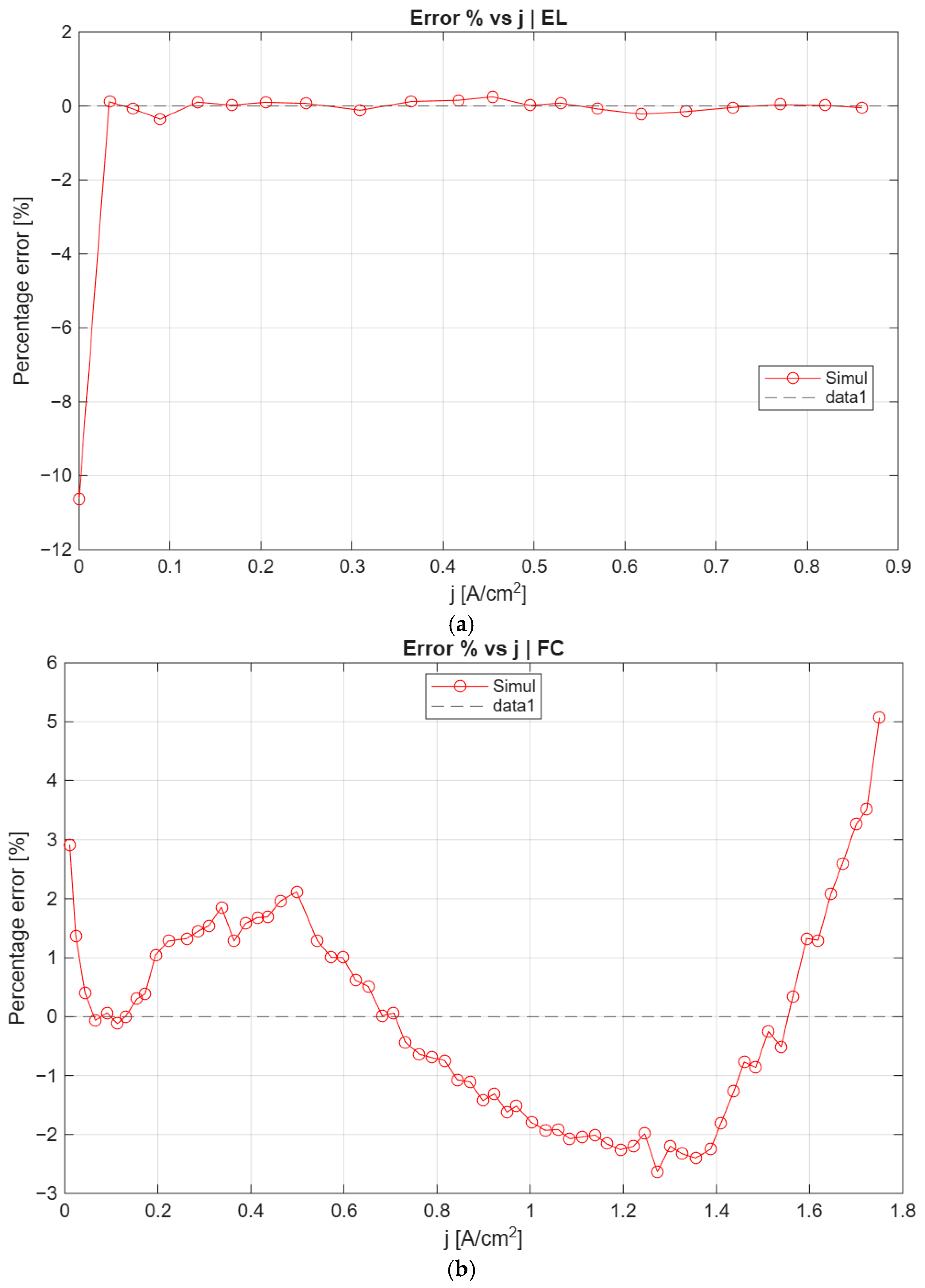
After calibration, the error is significantly reduced and remains close to zero across the full operating range, as shown in
Figure 2. The absence of trend and the reduced amplitude confirm that the calibrated model correctly captures the electrochemical behavior in electrolyzer mode. In fuel cell mode, the initial model shows large deviations, with errors exceeding 15–20% at low current density and decreasing gradually with increasing load. The calibrated model drastically reduces these errors, maintaining them within approximately ±2–5% over most of the operating range. This improvement is particularly relevant in the medium-current region, where practical operation typically occurs.
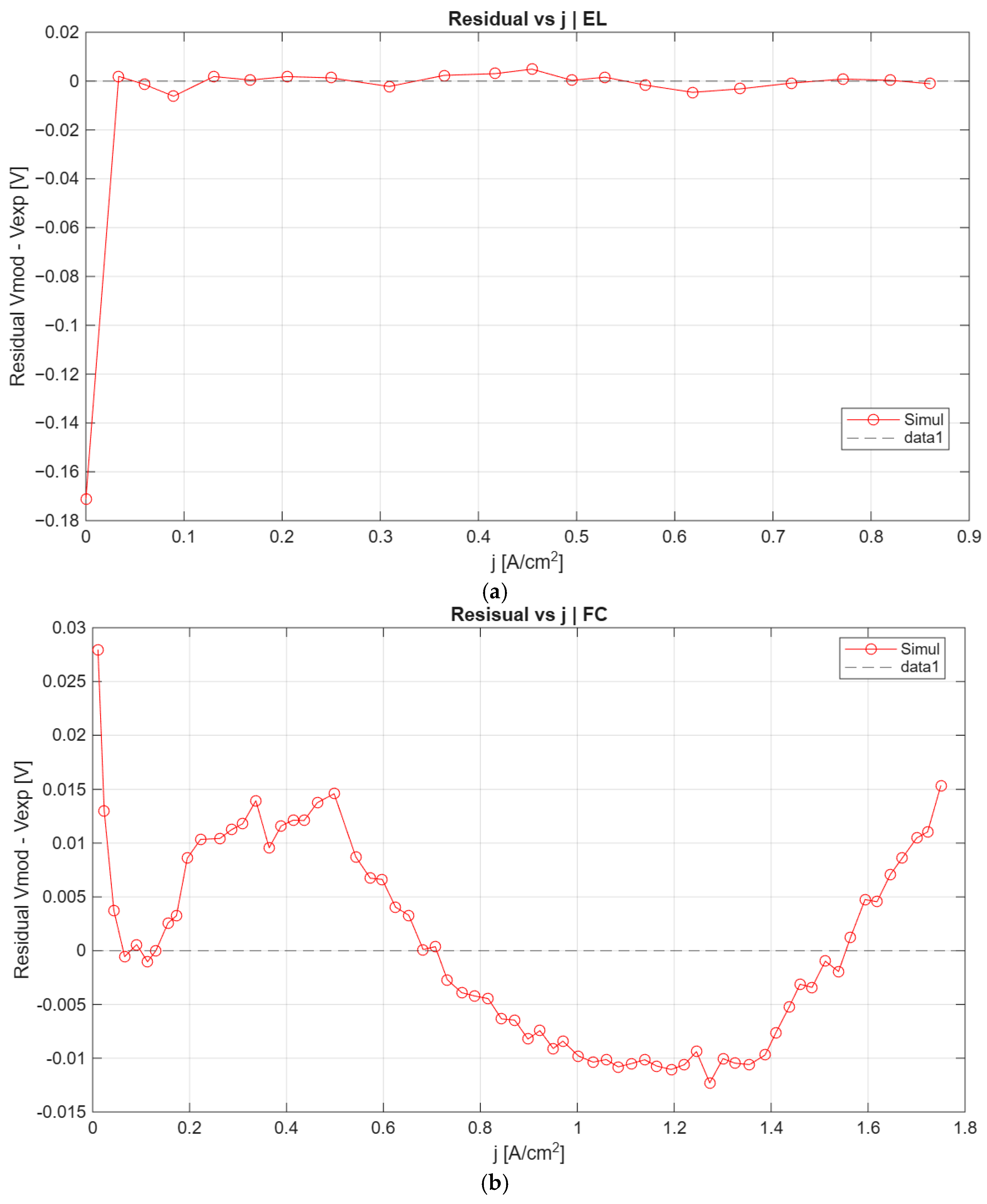
The initial model shows a strong negative trend in residuals, indicating systematic overprediction of voltage at higher current densities. After calibration, as shown in
Figure 3, residuals are significantly reduced and remain close to zero across the full current range. The improvement is particularly evident at medium and high current densities, confirming that the calibrated model accurately reproduces the polarization curve shape, maintaining values within approximately ±0.01–0.02 V. This confirms the effectiveness of the calibration in stabilizing model predictions across all operating conditions.
The calibrated model accurately reproduces the experimental polarization curve, capturing both the monotonic increase in voltage and the curvature of the response, as shown in
Figure 4. The initial model underestimates the voltage, particularly at higher current densities, while the calibrated model aligns closely with experimental data. This confirms that the model is suitable for predicting electrolyzer performance over the full operating range. In fuel cell mode, the calibrated model significantly improves agreement with experimental data, particularly in the medium-to-high current region. The convergence of curves at higher current density is especially important for practical applications.
To extend the analysis beyond electrochemical behaviour, the thermal behaviour is considered. The stack thermal characterization is modelled with the parameters listed in
Table 5.
The increased active area is used to generate a more realistic heat load, allowing the evaluation of temperature rise and cooling requirements. The model assumes uniform temperature distribution across the stack.
These thermal values are derived from PEM electrolysers. In fact, their composition—and thus their thermal behaviour—is assumed to be similar to that of rPEM cells (more than PEM fuel cells). The thermal capacity of the stack was estimated based on the maximum power output and the number of cells in the stack, using an average value across various electrolysers [
23] for the specific thermal capacity per unit of power.
Then, the number of cells was set to 100 to obtain values of the same order of magnitude as the stacks from which the other thermal parameters were derived. Regarding the total thermal resistance of the stack, the influence of the number of cells was neglected, since the contribution of the stack’s lateral surface area to heat transfer (which increases with the number of cells) was considered negligible compared to that of the base. An average value derived from various electrolysers reported in the literature was assumed [
23].
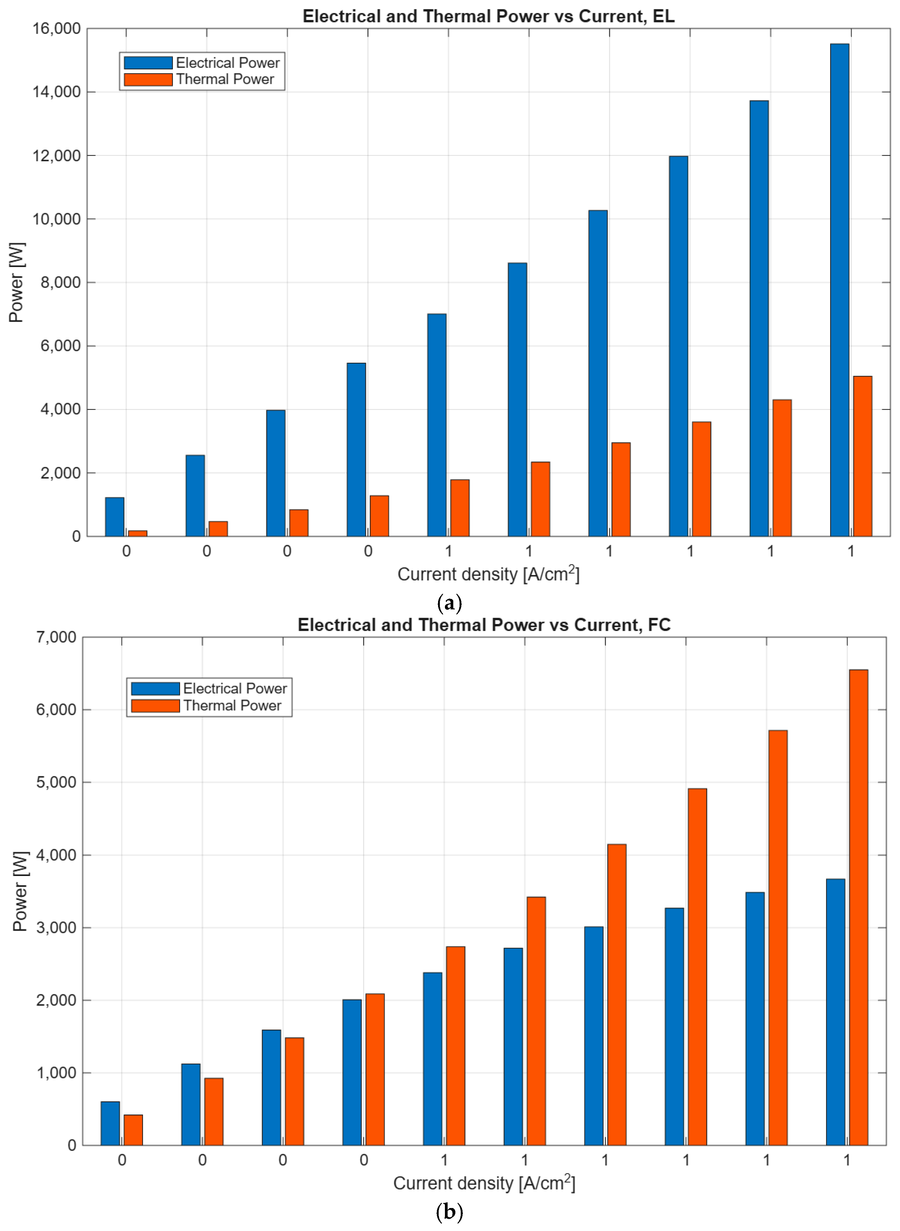
Thermal effects play a critical role in system performance, particularly at high current density. The analysis shows that, in fuel cell mode, efficiency decreases with increasing load due to higher overpotentials and heat generation. However, part of this thermal energy can be recovered, improving overall system efficiency. In electrolyzer mode, efficiency remains higher but still benefits from thermal integration. The results indicate that heat recovery becomes increasingly important at high current density, where thermal losses are significant.
The efficiency trends differ significantly between FC and WE modes. In fuel cell mode, stack efficiency decreases from approximately 0.78 at low current to about 0.40 at 1 A. At the system level, efficiency decreases from 0.67 to 0.37. However, when heat recovery is considered, total system efficiency increases to approximately 0.66 at high current density. In electrolyzer mode, stack efficiency remains higher, decreasing from 0.98 to approximately 0.71. System efficiency decreases from 0.84 to 0.71, while heat recovery increases total efficiency up to approximately 0.76.
These results demonstrate that thermal integration becomes increasingly important at high current density, where heat generation is significant.
In
Figure 5, it is possible to see the trends of electrical and thermal power output measured at the same operating temperatures used to obtain the polarization curves.
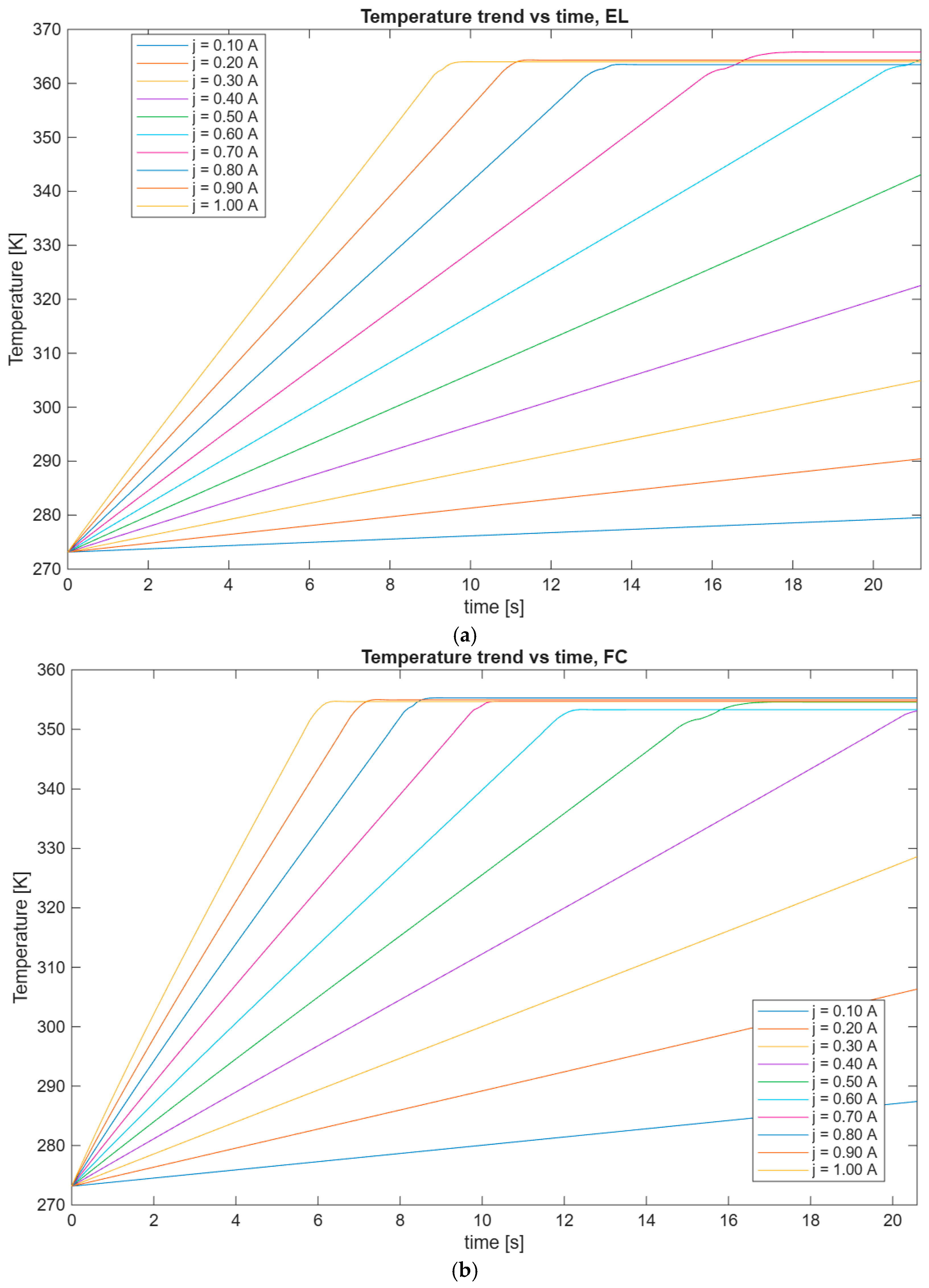
Furthermore, the thermal evolution as a function of various discharge current levels, recorded after a 5-min operational interval, can be observed in
Figure 6.
After calibration, the reversible cell model demonstrated a substantial increase in predictive accuracy in both fuel cell (FC) and water electrolysis (WE) operating modes. In FC mode, the calibrated model achieved an RMSE of 9.2 mV, corresponding to a relative error of 1.72%, with an excellent coefficient of determination (R2) equal to 0.9973. In WE mode, the calibrated configuration yielded an RMSE of 37.4 mV and an RMSE% of 2.32%, with an R2 value of 0.9997, confirming the high agreement between experimental and simulated results. Moreover, for the practical electrolyzer operating region (j > 0), the relative error further decreased to 0.13%, with a mean absolute percentage error (MAPE) of 0.10%, indicating near-perfect predictive capability of the calibrated model under realistic operating conditions.
Residual analysis further confirmed the robustness of the calibration process. In FC mode, the residual distribution was confined within a narrow range between −0.02 V and +0.02 V, while in WE mode the residuals were limited between −0.01 V and +0.01 V. These results demonstrate the strong capability of the calibrated model to accurately reproduce the electrochemical behavior of the reversible cell across both operating regimes, ensuring high reliability for simulation, control, and system-level integration studies.
4. Preliminary System-Level Sizing Case Study
The calibrated polarization relation was used to translate cell-level voltage–current behaviour into preliminary estimates of stack current, stack voltage, gross power, hydrogen throughput, thermal duty and major balance-of-plant requirements. For a selected current density and active cell area, the cell current is obtained from the product of current density and active area, whereas the stack voltage is calculated by multiplying the cell voltage by the number of cells connected in series. The resulting stack power is then combined with conversion losses and auxiliary consumption to estimate the nominal system rating in fuel-cell and water-electrolysis operation.
The case study considers a shared reversible PEM stack rated at 100 kW in fuel-cell mode and 300 kW in water-electrolysis mode. The selected configuration targets a symmetric hydrogen throughput of approximately 6 kg h
−1, a short-term hydrogen buffer corresponding to approximately one hour of nominal fuel-cell operation, and shared cooling and water-management infrastructure. The main assumptions and sizing results are summarized in
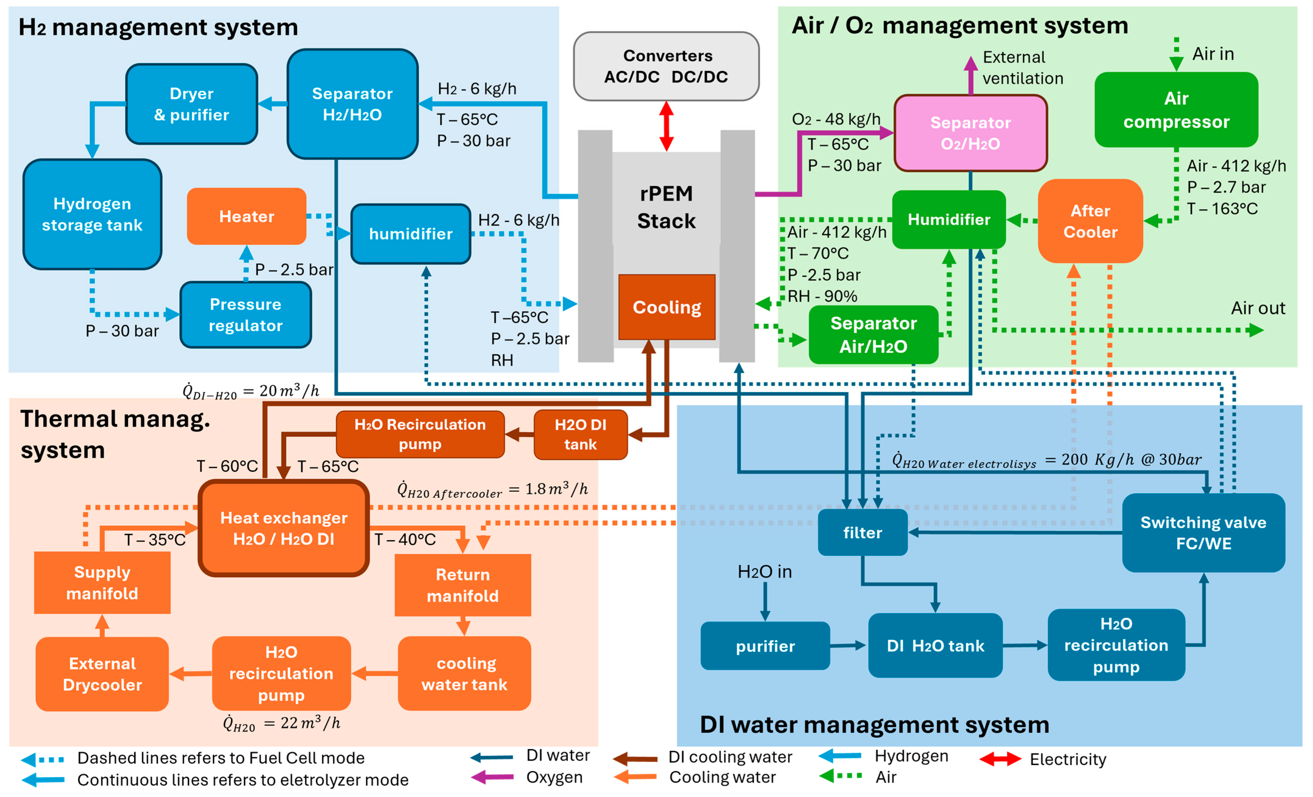
Table 6, while
Figure 7 presents the functional architecture.
The system-level results should be interpreted as preliminary sizing estimates. The present model does not resolve stack-scale flow maldistribution, cell-to-cell voltage dispersion, local temperature gradients, manifold pressure losses, spatial hydration non-uniformity or transient switching behaviour. In addition, the selected design conditions do not fully coincide with the conditions of the literature dataset used for model calibration. The case study therefore provides an internally consistent basis for preliminary BoP sizing, rather than a validated prediction of a large-scale reversible PEM stack.
Once the calibrated polarization relation
V(
j,
T,
p) is available (
Section 2), the transition to system scale is formalised as a two-step aggregation. At the stack level, for a given operating current density
j and an active area
Acell, the cell current is
I =
j·Acell. The stack voltage is obtained as
Vstack =
Ncell·
V(
j,
T,
p), where
Ncell is selected to meet the required nominal power:
At the system level, the electrical power delivered (FC) or absorbed (WE) is obtained by applying the Balance of Plant (BoP) efficiency chain:
with η
conv accounting for AC/DC and DC/DC conversion losses and P
aux representing the parasitic consumption of the air blower, pumps, heaters, dryer and instrumentation. The calibrated electrochemical model thus defines the stack operating envelope, while Equations (11) and (12) propagate these predictions to the nominal system ratings of 100 kW (FC) and 300 kW (WE).
All Balance-of-Plant components (filters, separators, vents, purge lines, humidifier, cooling circuit, dryer) are sized with a uniform design margin SF = 0.25 on top of the nominal flow rates, to account for load ramps, purge transients, safety margins and performance degradation over the component lifetime:
This common margin policy, adopted consistently throughout
Section 4.1, guarantees that each component is selected on a conservative duty point while preserving the symmetry of the hydrogen loop.
4.1. Balance of Plant Considerations
Hydrogen flow is maintained symmetric between the two modes, simplifying system control and storage management. Oxygen produced during electrolyzer operation is vented externally, reducing system complexity. Nitrogen is used within the balance of plant to purge the system during transitions between operating modes, preventing gas mixing and ensuring safe operation.
The functional schematic presented in
Figure 7 provides a comprehensive representation of the reversible PEM system, highlighting the integration of hydrogen, air/oxygen, thermal, and deionized water subsystems within a single architecture. Unlike conventional systems based on separate electrolyzer and fuel cell units, the reversible configuration requires a high degree of integration and bidirectional operability, which significantly increases both design complexity and control requirements. From a mass-flow perspective, the system is designed to operate with a symmetric hydrogen throughput of approximately 6 kg h
−1 in both fuel cell and electrolyzer modes. This design choice simplifies storage sizing and ensures balanced operation across charge and discharge cycles. In addition, it also simplifies the stack flow channel geometry design, having similar gas flow rates in the two working modes. Hydrogen produced during electrolyzer operation at 30 bar and approximately 65 °C is routed through a separation and purification stage before being stored or redirected to the stack. During fuel cell operation, hydrogen is regulated to 2.5 bar and conditioned in terms of temperature and humidity (RH ≈ 90%) to ensure optimal membrane hydration and electrochemical performance.
The oxygen/air management subsystem reflects a key design trade-off. In electrolyzer mode, oxygen is produced at elevated pressure (up to 30 bar) and moderate temperature (≈65 °C) and is vented externally rather than stored, reducing system complexity and safety constraints. In fuel cell mode, air is supplied via a compressor, with flow rates exceeding 400 kg h−1 (including BoP margin), and is conditioned through humidification and thermal control stages. The use of air instead of pure oxygen in FC mode represents a practical compromise between efficiency and system simplicity, albeit at the cost of increased parasitic losses. Thermal management plays a central role in ensuring stable operation across both modes. The system includes a dedicated cooling loop with water recirculation, heat exchangers, and external dry coolers. Heat generation differs significantly between modes: in fuel cell operation, heat is produced as a byproduct of electrochemical conversion and increases with current density, while in electrolyzer mode, heat is generated primarily due to overpotentials and ohmic losses at high voltage. The cooling system is therefore designed to handle variable thermal loads, with flow rates exceeding 20 m3 h−1 in the main loop. Maintaining stack temperature within a narrow range (65–70 °C) is critical to preserving membrane durability and performance. The deionized water management subsystem is essential for electrolyzer operation and includes storage, filtration, purification, and recirculation components. Water consumption in electrolyzer mode is directly linked to hydrogen production (approximately 9 kg of water per kg of H2), requiring a continuous supply and careful control of purity to avoid membrane degradation. The inclusion of a switching valve between FC and WE modes enables dynamic reconfiguration of flow paths, allowing the same hardware to operate under different regimes.
A key additional feature is the use of nitrogen purging during transitions between operating modes. This is necessary to avoid mixing of hydrogen and oxygen within the stack and piping, which would pose significant safety risks. The purge system is integrated within the balance of plant and is activated during startup, shutdown, and mode switching phases.
Compared to systems with separate fuel cell and electrolyzer units, the reversible architecture offers clear advantages in terms of compactness, reduced capital cost, and shared balance of plant components. However, these benefits come at the expense of increased system complexity, stricter operational constraints, and the need for highly coordinated control strategies. In particular, components such as humidifiers, heat exchangers, and gas management units must operate efficiently under both modes, which often have conflicting requirements in terms of pressure, temperature, and flow rates. Overall, the schematic highlights that the design of a reversible PEM system is not simply the superposition of a fuel cell and an electrolyzer, but rather a tightly integrated system in which electrochemical, thermal, and fluid dynamic phenomena must be simultaneously managed.
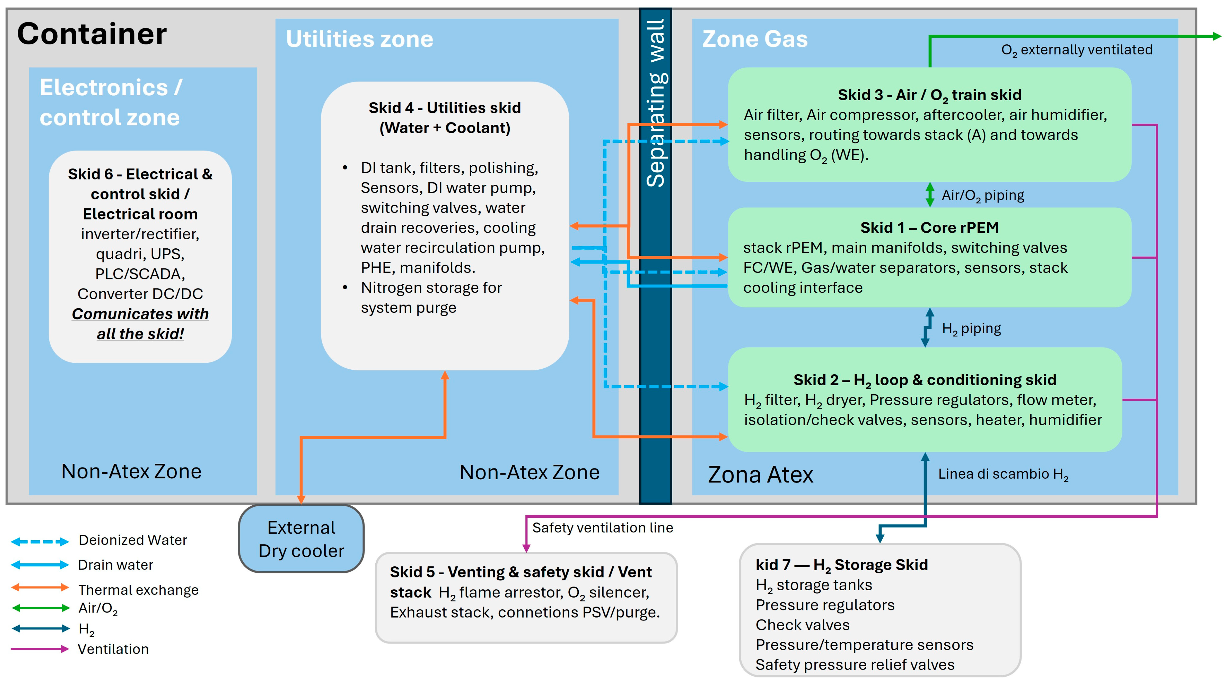
Figure 8 illustrates the physical implementation of the reversible PEM system within a containerized configuration, emphasizing modularity, safety, and industrial scalability. The system is organized into multiple functional skids, each dedicated to a specific subsystem, enabling a clear separation of roles and facilitating maintenance and operational flexibility. The container layout is divided into ATEX and non-ATEX zones, reflecting the presence of flammable gases such as hydrogen. The ATEX zone includes the core PEM stack and gas handling components, while the non-ATEX zone houses electrical systems, control units, and auxiliary equipment. This separation is essential for ensuring compliance with safety regulations and minimizing the risk of ignition. The PEM core skid (Skid 1) represents the central element of the system and includes the stack, manifolds, and switching valves that enable reversible operation. The design is derived from high-pressure electrolyzer configurations (30 bar), ensuring mechanical robustness under both operating modes. The hydrogen loop (Skid 2) includes filtration, drying, pressure regulation, and recirculation systems, ensuring that hydrogen quality and pressure are maintained within required limits for both FC and WE operation.
The air/oxygen skid (Skid 3) integrates compression, filtration, humidification, and heat exchange components. In fuel cell mode, the air compressor must deliver large flow rates at moderate pressure (≈2–3 bar), while in electrolyzer mode the oxygen stream is handled primarily for venting and safety. This dual functionality requires flexible component sizing and control strategies. Utilities (Skid 4) include water management and cooling systems, which are shared between modes. The deionized water loop supports electrolyzer operation, while the cooling circuit ensures thermal stability of the stack. The integration of these utilities into a single skid reduces system footprint but requires careful design to handle varying loads.
The venting and safety skid (Skid 5) includes flame arrestors, silencers, and purge systems, which are critical for safe operation during transient phases. The hydrogen storage skid (Skid 7) provides a buffer capacity of approximately 200 kWh, corresponding to one hour of full-power operation in fuel cell mode. This storage capacity is a key design parameter, enabling decoupling between hydrogen production and consumption.
Compared to traditional systems with separate electrolyzer and fuel cell units, the containerized reversible system offers significant advantages in terms of footprint reduction, component sharing, and installation simplicity. However, it also imposes stricter requirements on component compatibility and system control. For instance, compressors, heat exchangers, and piping must be designed to operate efficiently under both low-pressure FC conditions and high-pressure WE conditions. From an engineering perspective, the modular skid-based approach enhances scalability, allowing the system to be replicated or expanded to higher power levels. At the same time, it facilitates transportation and deployment in remote or distributed energy applications. The containerized layout demonstrates the practical feasibility of the proposed reversible PEM system and provides a clear pathway toward industrial implementation. The integration of multiple subsystems within a compact and modular architecture highlights the importance of system-level design considerations in the development of next-generation hydrogen energy systems.
4.1.1. Hydrogen Flow Sizing (Symmetric FC/WE Loop)
In FC mode the hydrogen mass flow rate is derived from the nominal electrical power, the lower heating value (LHV) of hydrogen (LHV
H2 ≈ 33.33 kWh/kg) and the nominal system LHV efficiency η
FC,LHV = 0.50, representative of stationary PEMFC systems operated at full load:
Substituting Pel,FC = 100 kW gives ṁH2,FC = 6.00 kg/h and, with ρN,H2 = 0.0899 kg/Nm3, a normal volumetric flow VN,H2 = 66.7 Nm3/h.
In WE mode the hydrogen production is driven by the specific system consumption e
spec,sys ≈ 50 kWh/kg:
Imposing ṁH2,WE = ṁH2,FC = 6 kg/h—the key architectural choice that yields a symmetric loop and a simplified BoP—requires Pel,WE ≈ 300 kW. Applying the BoP margin of Equation (13) leads to a design flow of 83.7 Nm3/h for all gas-side components (filters, separators, vents, purge).
4.1.2. Air and Oxygen Flow Sizing (FC and WE)
Both operating modes obey the same stoichiometric ratio between H
2 and O
2 (H
2 + ½ O
2 → H
2O), so that:
at the nominal design point V
N,O2,stoich = 33.4 Nm
3/h in both modes. In FC mode, air—rather than pure O
2—is supplied to the cathode with an oxygen excess ratio λ
air needed to prevent starvation and to assist water and thermal management. Typical values at full load lie in the range 1.6–2.5; the reference value λ
air = 2.0 is adopted for the preliminary sizing. With the oxygen molar fraction in dry air x
O2,air = 0.2095 the air volumetric flow is:
which yields V
N,air ≈ 320 Nm
3/h (ṁ
air ≈ 412 kg/h) nominal and 400 Nm
3/h with the BoP margin. In WE mode, the oxygen produced at the anode (≈33.4 Nm
3/h, i.e., 47.7 kg/h nominal) is vented externally, which simplifies the oxygen skid and removes any high-pressure O
2 storage requirement.
4.1.3. Cathode Air Conditioning (Compressor, Aftercooler, Humidifier)
The compressor raises the ambient air from P1 = 1.013 bar(a), T1 = 298 K to the cathode supply pressure P2 = Pstack + Δpline = 2.5 + 0.2 = 2.7 bar(a), i.e., a compression ratio π = 2.66. The outlet temperature is obtained from the isentropic relation corrected by the isentropic efficiency η
is ≈ 0.70:
with γ = 1.4, η
mech = 0.95 and η
motor = 0.92–0.96 the thermodynamic duty is 15.8 kW, translating into a motor size of ≈18 kW. The resulting selection is an oil-free, ATEX-compatible centrifugal blower.
The aftercooler brings the compressed air from T
2 ≈ 163 °C back to the stack inlet temperature T
3 = 70 °C. The thermal duty and the required thermal conductance are:
Applying a 20% fouling/uncertainty margin on heat exchange coefficient and area (UA) and a preliminary range U ∈ [200, 300] W/(m2 K) for a gas–liquid plate heat exchanger yields QAC ≈ 10.7 kW, ΔTlm ≈ 69 °C and A ∈ [0.62, 0.93] m2. The selected unit is a brazed plate heat exchanger with 26 plates.
As for the cathode humidifier, the amount of water to be transferred to the cathode stream is determined from the psychrometric balance across the humidifier. The humidity ratio at the outlet is:
at T = 70 °C, P = 2.5 bar(a), RH = 90%, p
sat(70 °C) = 31.2 kPa, the required water addition is 28.2 kg/h (nominal) and 32.3 kg/h at full saturation. The cathode exhaust is used as a passive vapour source (gas/gas hollow-fibre humidifier), with a DI water make-up line sized for 10 kg/h (continuous) to cover the residual deficit at the 90% RH target.
4.1.4. Thermal Balance and Cooling Loop
The heat to be removed from the stack is evaluated from the overall energy balance in each mode:
with the nominal design point both expressions yield Q
loss ≈ 100 kW. Introducing the thermal split factor f
cool (fraction of the total losses actually removed by the coolant loop, typical range 0.7–0.9), the conservative sizing assumption f
cool = 1 is adopted. The coolant mass flow is then:
with c
p,w = 4.18 kJ/(kg·K), the design ΔT
cool is 5–10 °C in FC and ≤5 °C in WE, the more stringent limit being imposed by the water-electrolyzer mode to preserve thermal uniformity along the stack. The sizing case (ΔT
cool = 5 °C) yields ṁ
w = 4.78 kg/s, i.e., ≈17–18 m
3/h, raised to 20 m
3/h with a 10–15% design margin. The loop features a primary DI-water circuit in direct contact with the stack and a secondary technical-water loop coupled to an external dry-cooler through a plate-and-frame heat exchanger (UA
design ≈ 4.8 kW/K, A ≈ 1.1–1.9 m
2).
4.1.5. Deionized Water Demand and Anode Recirculation (WE)
The stoichiometric water demand of the anodic reaction 2 H
2O → 2 H
2 + O
2 gives a one-to-one molar ratio between water consumed and hydrogen produced. In mass terms:
yielding 54 kg/h (0.054 m
3/h) of water consumed at 6 kg/h hydrogen production. The actual anode feed must, however, exceed the stoichiometric value by a factor ζ (water stoichiometry) to guarantee membrane hydration, uniform flow distribution, and effective removal of O
2 bubbles from the anodic channels. Values of ζ = 3–5 are reported as the minimum safe range for PEMWE systems with dedicated cooling [
45]. Adopting the conservative lower bound ζ = 3 and the BoP margin of Equation (13):
so that 54 kg/h are actually split electrochemically and ≈146 kg/h are recirculated. Water quality is preserved by a dedicated filtration and ion-exchange loop targeting a conductivity below 1 μS/cm.
4.1.6. Hydrogen Buffer Sizing
The hydrogen storage is conceived as a short-term buffer, not as a long-duration energy reservoir, consistently with the symmetric design of the FC/WE loop. Starting from the ideal gas assumption for hydrogen at 30 bar(g), the usable mass between the maximum and minimum operating pressures (P
max = 31 bar(a), P
min = 6 bar(a), still compatible with downstream regulation to the FC stack at 2–3 bar(a)) is:
imposing m
usable = 6 kg (i.e., 1 h of full-load FC operation, ≈200 kWh
chem or ≈100 kWh
el at 50% FC efficiency) yields V
tank ≈ 2.67 m
3. The preliminary size of 2.5–3.0 m
3 at 30 bar(g) is therefore consistent with the architectural target of a 1 h autonomy buffer in FC mode.
4.1.7. Pump Sizing—Specific-Speed Criterion
Two distinct hydraulic machines are available for the application requirements: (i) a centrifugal multistage pump for the DI cooling loop (Q ≈ 20 m
3/h, H ≈ 15 m c.a.) and (ii) a positive-displacement diaphragm pump for the anode DI supply, which must overcome the 30 bar(g) system pressure. The choice of technology is driven by the specific speed:
For the anode DI pump at the nominal design point (Q = 0.25 m
3/h, H = 326 m c.a., n = 2900 rpm) Equation (33) yields N
s ≈ 0.32, well below the operating range of conventional centrifugal pumps (N
s ∈ [0.5, 3.5]). The hydraulically actuated diaphragm pump is therefore selected as the only viable option, delivering a flow independent of pressure and avoiding any mechanical seal on the DI fluid. The hydraulic and electrical power are:
assuming η ≈ 0.45 for a diaphragm pump in this size class, P
h ≈ 222 W and the selected commercial size is 0.55 kW.
4.1.8. Nitrogen Inventory for Purging and Safe Operation
Nitrogen is used to inert and purge the process circuits before each FC-WE transition, at cold start, and at shutdown, preventing explosive H
2/O
2 mixtures inside the BoP (IEC 62282-3-200 [
46]). The inventory is sized by estimating the total volume to be purged, the number of volume changes required to reach the safety target concentration, and the number of events between refills.
The stack channel volume is derived from the active area A
cell = 1500 cm
2, channel depth h
ch ≈ 0.8 mm, filling factor f = 0.40 and manifold correction k
man = 1.20:
Adding the internal volumes of the selected BoP components (coalescing separators, heater, humidifiers, aftercooler) and the interconnecting piping (DN25 H2 line, DN50 air/O2 line) plus a 15% margin for fittings gives Vtot ≈ 32 L.
Under the perfectly mixed assumption the residual gas fraction after n
v volume changes at purge pressure Ps = 3 bar(a) is Cf/C
0 = exp(−n
v). The ATEX safety target C
f < 1% vol (=25% of the H
2 LEL) requires n
v ≈ 4.6, rounded up to 5. The N
2 consumed per event and the total demand over n
ev = 20 events (2 daily transitions × 7 days + start-up/shutdown + ESD margin) are:
Using 200 bar(g) cylinders (EN ISO 9809-1 [
47]) with a minimum residual pressure of 20 bar(g), the utilisation factor is η
util = 0.90 and the required geometric volume is:
The commercial selection is a manifold of two 50 L/200 bar(g) cylinders (100 L geometric, 18 Nm
3 usable ≈ 30 events), allocated in Skid 4 with a footprint of 0.60 × 0.30 m and a full-charge assembly weight of ≈154 kg. A two-stage ATEX-certified regulator, a fail-safe solenoid valve and a mass-flow meter complete the line. Nitrogen purity ≥ 99.998% (EN ISO 14175 class 4.8 [
48]) is specified to prevent membrane contamination from residual O
2 or moisture.
4.1.9. Ventilation System
The venting and safety skid (Skid 5) provides the passive and active barriers required for safe hydrogen and oxygen handling during all transient phases, in compliance with ATEX Directive 2014/34/EU, Workplace Directive 1999/92/EC and the hydrogen-specific provisions of ISO/TR 15916:2015 [
49]. The container interior is maintained under continuous forced ventilation, with air supply at low level and exhaust at ceiling level: because hydrogen is positively buoyant (ρ/ρ_air ≈ 0.07), this top-extraction layout prevents stratification and ensures that the local H
2 concentration remains below 25% of the lower flammability limit (1% vol) under any credible minor leak scenario. Catalytic H
2 sensors are mounted in the upper volume of the ATEX zone and are interlocked with the emergency shutdown (ESD) logic: a first threshold at 10% LFL triggers a ventilation boost and a control-room alarm, while a second threshold at 25% LFL initiates automatic isolation of the gas lines and nitrogen purging of the stack circuits. All hydrogen and oxygen vent lines are routed to a common discharge point external to the container, fitted with stainless-steel flame arrestors (EN ISO 16852 [
50]) and low-pressure silencers to attenuate impulsive releases during purge events. The oxygen vent line from the WE anodic circuit is segregated from the hydrogen vent and rises vertically to the discharge point to exploit natural buoyancy and to prevent any accumulation of O
2-enriched atmosphere inside the enclosure.
4.2. Comparison with Separated Systems
A key design question in hydrogen-based energy systems concerns whether the conversion block should be implemented as a single reversible PEM unit or as two distinct devices, namely a dedicated PEM electrolyzer and a dedicated PEM fuel cell. Although both approaches can provide the same high-level functionality, they differ substantially in terms of architecture, efficiency distribution, capital cost, component redundancy, and operational flexibility.
The reversible PEM approach offers a clear advantage in terms of compactness and equipment integration. Since the same stack core is used in both water electrolysis and fuel cell modes, a significant portion of the electrochemical hardware is shared. This reduces the number of electrochemical modules, potentially lowers footprint, and simplifies installation. In addition, a reversible configuration can share part of the balance of plant, including thermal management, hydrogen conditioning, water handling, sensors, manifolds, and supervisory control logic. These features make the rPEM approach particularly attractive for stationary systems in which compactness and architectural integration are important design drivers.
However, these benefits are associated with non-negligible trade-offs. A reversible stack must satisfy the requirements of both modes with the same electrochemical core and with a partially shared set of auxiliaries. This imposes stricter constraints on materials, sealing, gas management, thermal design, and control. In practice, the stack and BoP cannot be optimized independently for electrolyzer and fuel cell operation, as would be possible in separated systems. As a result, the reversible architecture often involves a compromise between the ideal design point for FC operation and the ideal design point for WE operation.
By contrast, a system based on separated PEM fuel cell and PEM electrolyzer units enables mode-specific optimization. The electrolyzer can be designed for high-pressure hydrogen production, low degradation under anodic potentials, and optimized water management, while the fuel cell can be independently optimized for air stoichiometry, humidification, and part-load efficiency. This generally improves design freedom and may reduce control complexity during steady-state operation. On the other hand, separate units require duplicated electrochemical hardware and, to a large extent, duplicated balance of plant, leading to higher capital expenditure, greater footprint, and increased integration effort.
These differences are summarized in
Table 7.
From a techno-economic perspective, the reversible approach is likely to be preferable when footprint reduction, integration, and hardware minimization are more important than full mode-specific optimization. This is typically the case for compact stationary systems, modular containerized units, remote installations, and applications requiring frequent alternation between charging and discharging. Separate fuel cell and electrolyzer units may instead remain advantageous in applications where the two modes operate on different schedules, where maintenance accessibility is critical, or where maximum single-mode efficiency is prioritized over architectural compactness.
In the present study, the reversible architecture is selected because the target application emphasizes compactness, symmetric hydrogen throughput, and integration within a containerized 100 kW/300 kW system. Under these assumptions, the reduced footprint and the sharing of key subsystems represent a meaningful advantage, provided that the control system is sufficiently robust to manage transient phases and dual-mode constraints.
The preliminary design carried out in
Section 4.1 provides a concrete, component-level substantiation of the arguments discussed above. The main advantages of the reversible, containerized configuration over a separated FC + WE system can be quantified along four axes.
A single rPEM stack (480 × 480 mm cross-section, ≈700 mm length, design mass ≈ 650 kg) simultaneously fulfils the 100 kW FC and 300 kW WE duties. In a separated architecture, two distinct electrochemical units would be required, each with its own end-plates, current collectors, tie rods and hydraulic manifolds. The reversal of polarity and the mechanical design dominated by the WE high-pressure condition (30 bar(g)) result in a stack that structurally resembles a PEM electrolyzer—as anticipated in
Section 4—while still being dimensionally compatible with a standard 40 ft container.
Because the WE mode produces hydrogen directly at 30 bar(g), the gas can be routed to the storage buffer without any intermediate recompression. In a system where the electrolyzer operates at lower pressure, an additional H
2 compressor would be required to reach storage conditions—a component that introduces parasitic electrical consumption (typically 15–20 kW for the 67 Nm
3/h flow rate of this plant), mechanical complexity and an additional ATEX-classified rotating machine inside the container. The asymmetric pressure strategy (
Section 4.1) therefore translates directly into a reduction in both installed power and plant footprint.
The design demonstrates multiple instances of true hardware sharing between the two modes. The 125 kW dry-cooler (Kelvion LF-PA202L3H-Kelvion Holding GmbH, Herne, Germany) handles the entire heat rejection of both FC and WE operation through a single technical-water loop: in both modes the stack thermal duty is ≈100 kW and the aftercooler contributes a further 11 kW in FC mode, giving the same total dissipation. The 500 L deionised water tank and the LEWA diaphragm pump serve opposite water balances—a net surplus of ≈43 kg/h in FC and a net demand of ≈54.5 kg/h in WE—without duplicating any hydraulic circuit. The same Classic Filters SHS425.841 coalescing separator is installed on both the H2 and O2 lines (the O2 unit being oxygen-cleaned to ASTM G93), and the same Kelvion GBS 400H plate heat exchanger family serves as both the aftercooler (26 plates) and the DI/technical-water stack exchanger (40 plates), simplifying procurement, spare-parts management and maintenance qualification.
All active subsystems are integrated within a standard 40 ft container organized into five functional skids. The largest single footprint belongs to Skid 3 (air/O2 management) at 1600 × 1500 mm, driven by the 770 kg oil-free compressor (1350 × 1250 × 1770 mm). The complete system—including stack, power electronics, thermal management, gas conditioning, water treatment and nitrogen safety circuit—is therefore self-contained, transportable and deployable without on-site civil works beyond the connection of external utilities (grid, water supply, dry-cooler).
These outcomes confirm the assessment of
Table 4: the reversible containerized architecture delivers a meaningful advantage in compactness and hardware minimisation relative to separated systems, provided that the control complexity of dual-mode operation—in particular the nitrogen purge sequences and the pressure reconfiguration described in
Section 4.3 and
Section 4.4—is properly managed. The trade-off between hardware reduction and operational complexity is therefore the central design tension of rPEM technology, and the quantitative results of this study show that it can be resolved favourably at the 100 kW/300 kW scale through careful co-design of the electrochemical operating envelope and the BoP architecture.
4.3. Control Strategy for Reversible PEM System Operation
The operation of a reversible PEM system requires a supervisory control architecture significantly more sophisticated than that of conventional single-mode electrochemical systems. This is due to the need to coordinate electrochemical conversion, gas routing, water supply, thermal regulation, pressure management, and safety logic under two fundamentally different operating modes. The control problem is therefore inherently multi-domain, involving electrical, thermal, fluid dynamic, and process-safety variables.
At the highest level, the system controller determines the operating mode as a function of external power demand, hydrogen storage state, grid or renewable power availability, and system readiness. Fuel cell mode is typically activated when electrical power is required and a sufficient hydrogen inventory is available. Water electrolysis mode is instead selected when excess electrical power is available and the hydrogen storage system has remaining capacity.
Once the operating mode has been selected, the supervisory controller must ensure that all boundary conditions required for safe and efficient stack operation are met before electrochemical current is applied. This includes verification of gas-line pressure, purge completion, coolant circulation, humidity conditions, and valve positions. As a result, the reversible PEM system is best controlled through a hierarchical architecture with three main levels: a supervisory energy management layer, a process coordination layer, and a fast actuator/control layer.
The supervisory layer evaluates system objectives such as energy balancing, hydrogen storage utilization, and power dispatch. For the configuration considered in this work, this layer must reconcile a 100 kW fuel cell discharge capability with a 300 kW electrolyzer charging capability and with a hydrogen storage buffer of approximately 200 kWh. Because the hydrogen throughput is designed to be symmetric at approximately 6 kg h−1, supervisory decisions must also account for the temporal balance between hydrogen production and consumption.
The process coordination layer is responsible for preparing and stabilizing the system in the selected mode. In fuel cell operation, this includes hydrogen pressure regulation to approximately 2.5 bar, cathode air supply control, humidification to about 90% relative humidity, and thermal stabilization around 70 °C. In electrolyzer mode, the same layer must ensure deionized water availability, oxygen handling readiness, pressure buildup toward 30 bar, and thermal stabilization around 65 °C. These conditions are substantially different and require explicit reconfiguration of the fluidic and thermal network.
The actuator layer performs the fast regulation of physical variables such as stack current, coolant flow, hydrogen recirculation, compressor speed, humidifier duty, and valve positioning. Local PID or model-based loops are particularly suited for this level, since they must respond rapidly to variations in current demand, temperature, or pressure. Current control is especially important because it directly affects both electrochemical performance and thermal generation. Similarly, pressure control must maintain stable differentials across the stack while avoiding excessive transients that could damage seals or accelerate degradation.
A robust control strategy should monitor at least the variables listed in
Table 8.
An important feature of the control strategy is the need to coordinate efficiency optimization with durability preservation. For example, operating at high current density may maximize power throughput in the short term, but it also increases overpotentials, thermal stress, and water-management sensitivity. The controller should therefore avoid unnecessarily aggressive transients and should favour smooth ramping, particularly during startup and shutdown.
In practical deployment, advanced control techniques such as model predictive control may be especially beneficial for rPEM systems. Because the process includes coupled constraints on pressure, temperature, storage level, and power demand, predictive control can improve transient management and reduce oscillatory behavior. Even when simpler PID-based structures are used at the lower level, a model-based supervisory layer remains highly desirable.
Overall, the control system is not a secondary design element but a central enabling technology for reversible PEM operation. The effectiveness of the integrated architecture depends directly on the ability of the controller to manage shared components under strongly different electrochemical and thermodynamic conditions.
4.4. Dynamic Operation and Mode Switching Analysis
One of the most distinctive features of a reversible PEM system is its ability to alternate between hydrogen production and power generation using the same electrochemical core. This characteristic introduces an additional degree of operational flexibility, but it also creates one of the most critical engineering challenges of the entire system, namely the safe and efficient transition between fuel cell and electrolyzer modes.
In steady-state operation, the system behavior can be described by the calibrated electrochemical and thermal models discussed in the previous sections. However, during mode transitions, the plant enters a transient regime in which pressures, gas compositions, temperatures, and fluid routing states evolve simultaneously. If not properly managed, these transients can lead to gas crossover, local starvation, membrane dehydration or flooding, large pressure gradients, and electrochemical stress. For this reason, switching between modes must be treated as a controlled sequence rather than as an instantaneous command.
A typical transition from fuel cell to electrolyzer operation begins with a controlled reduction in stack current to zero, followed by isolation of the reactive gas lines and depressurization or rebalancing of the relevant process volumes. Since hydrogen and oxygen must never coexist in unsafe concentrations in the stack or manifolds, an intermediate purge phase is required. In the present architecture, nitrogen is used for this purpose, ensuring removal of residual gases from the BoP and from the stack channels before the new operating mode is initiated. After purging, the system is reconfigured by switching the appropriate valves, activating the deionized water supply path, and progressively increasing pressure and flow conditions suitable for electrolyzer operation. Only once temperature, pressure, and water recirculation are stabilized can current be applied in WE mode.
The reverse transition, from electrolyzer to fuel cell operation, is equally critical. In this case, the stack must first be brought to zero current, oxygen-handling lines must be safely vented or isolated, and residual oxygen must be removed from the electrochemical core and gas manifolds. The hydrogen circuit is then conditioned for FC operation by reducing pressure from the high-pressure WE level toward the fuel cell setpoint of approximately 2.5 bar and by restoring the required humidification conditions. Since FC mode relies on air feed rather than anodic water supply, the cathode side must be reconfigured as well, including compressor startup and humidifier stabilization. The switching procedure demonstrates that reversible PEM operation requires strict sequencing and multi-variable coordination, with particular attention to:
Failure to properly control any of these aspects may result in performance degradation, safety risks, or irreversible stack damage. The switching sequence discussed in this section is intended as a qualitative operating framework and is not derived from a dedicated transient multiphysics simulation. The present analysis identifies the main actions required for a safe transition between FC and WE operation, including controlled current ramp-down, gas isolation, nitrogen purging, pressure equalization, reconfiguration of the fluidic paths, and thermal stabilization. The duration of these phases is not quantified in the present study because it depends on stack and manifold volumes, valve characteristics, purge-flow rates, pressure levels, coolant-loop inertia, and control settings. These dynamic sequences are summarized conceptually in
Table 9. The present work does not simulate the full transition. A predictive switching model, undergoing and as future work of the authors, will solve species balances for H
2, O
2, N
2, and water vapor; pressure dynamics in stack and manifolds; thermal inertia; crossover flux; valve and purge flow; and auxiliary energy. Accordingly,
Table 9 is presented as a safety-oriented operating logic rather than a validated transition-time prediction.
Although the transient switching process is not explicitly simulated, its system-level implications are considered in the proposed architecture. In particular, the nitrogen purge system, multi-way valve network, pressure-control devices, hydrogen-storage buffer, and shared cooling loop are included to enable safe and controlled mode transitions. These components affect the balance-of-plant sizing and operational strategy, since frequent switching may increase purge consumption, auxiliary energy use, and thermal-control requirements. For this reason, the proposed operating strategy is based on buffered scheduling, in which the hydrogen storage system reduces the need for rapid alternation between FC and WE modes.
Finally, the procedure emphasizes the importance of pre-start validation and controlled startup phases. These steps ensure that all boundary conditions are stable before reintroducing electrochemical current, thereby minimizing transient stress and ensuring reproducible operation. The inclusion of leak checks and system integrity verification further reinforces the safety-oriented design philosophy of the reversible system. The switching sequence is presented as a qualitative operating logic only. Transition duration, purge consumption, gas composition dynamics, pressure evolution and auxiliary-energy penalties were not simulated and must be addressed in future transient modelling and experimental work.
4.5. Design Summary
Table 10 provides a comprehensive overview of the main design parameters and subsystem functions of the proposed reversible PEM system, highlighting the multi-domain nature of the plant and the strong interdependence between electrochemical, thermal, and fluidic processes. The system is centered around a reversible PEM stack capable of operating as a 100 kW fuel cell and a 300 kW electrolyzer, reflecting an asymmetric power configuration that prioritizes rapid hydrogen production while maintaining sufficient discharge capability. The electrochemical core consists of a single reversible PEM stack comprising 91 cells electrically connected in series. Each cell has an active area of 1500 cm
2, resulting in a nominal stack current of 1500 A at a current density of 1.0 A cm
−2. In water-electrolysis mode, the nominal cell voltage is 2.2 V; therefore, the total stack voltage is 200.2 V and the corresponding gross electrical power input is approximately 300 kW. In fuel-cell mode, the same stack is designed to deliver 100 kW at the same nominal current density. The corresponding nominal stack voltage is 66.7 V, equivalent to an average cell voltage of approximately 0.733 V. The selected 91-cell configuration therefore provides an electrically consistent basis for the proposed 100 kW FC/300 kW WE reversible system.
The electrochemical core operates under significantly different conditions in the two modes, with pressures ranging from 2.5 bar in fuel cell operation to 30 bar in electrolyzer mode, and temperatures maintained within a narrow range between 65 °C and 70 °C. This dual operating envelope imposes stringent design requirements on materials, sealing, and mechanical robustness. In particular, the stack must withstand repeated pressure cycling while maintaining gas tightness and electrochemical performance. The hydrogen subsystem is designed around a symmetric flow rate of approximately 6 kg h−1, ensuring a balanced relationship between hydrogen production and consumption. The inclusion of a storage system with a capacity of approximately 200 kWh provides a one-hour buffer at nominal fuel cell operation, enabling partial decoupling between electrolyzer and fuel cell modes. This buffering capability is essential for reducing the frequency of mode switching and for accommodating fluctuations in external power demand or renewable energy availability. The air and oxygen subsystem reflects a clear distinction between the two operating modes. In fuel cell mode, a high air flow rate (on the order of 400 kg h−1) is required to supply oxygen for the electrochemical reaction, necessitating the use of a compressor and humidification system. In electrolyzer mode, oxygen is produced as a byproduct and is vented externally, simplifying system design and avoiding the need for oxygen storage. This choice reduces complexity and safety constraints but also implies that potential valorization of oxygen is not exploited.
Water management is a defining feature of the electrolyzer operation. The deionized water subsystem must provide a continuous and high-purity supply, with conductivity levels below 1 µS/cm to prevent contamination and degradation of the membrane. The integration of filtration, purification, and recirculation components ensures stable operation at the 300 kW scale. In contrast, water plays a secondary role in fuel cell mode, where humidification is required primarily to maintain membrane hydration. Thermal management is implemented through a shared cooling loop, with flow rates exceeding 20 m3 h−1 to handle the heat generated in both modes. The use of a common thermal system increases integration efficiency but requires careful control to accommodate the different thermal profiles of fuel cell and electrolyzer operation. Maintaining temperature uniformity across the stack is critical for both performance and durability.
The balance of plant includes several key elements that enable reversible operation, such as nitrogen purge systems, multi-way valve networks, and extensive sensor arrays. These components are essential for safe mode switching, real-time monitoring, and system control. In particular, the nitrogen purge system plays a central role in preventing hazardous gas mixtures during transitions.
Power electronics and control systems provide the interface between the electrochemical system and the external grid or load. The use of bidirectional converters enables seamless transition between power generation and hydrogen production, while a centralized PLC/SCADA system ensures coordinated control of all subsystems. The containerized configuration further enhances the practicality of the design by integrating all components into a modular, skid-based layout with clear separation between ATEX and non-ATEX zones. This approach supports scalability, ease of installation, and compliance with safety standards.
From a system-level perspective,
Table 10 highlights that the reversible PEM plant is not simply a combination of individual subsystems but a tightly integrated energy system in which each component must be designed and operated in coordination with the others. The interplay between hydrogen storage, thermal management, water supply, and electrochemical performance defines the overall system behavior and determines its efficiency, flexibility, and reliability.
5. Conclusions
This work presents a comprehensive framework for linking electrochemical modeling to system-level design in PEM reversible fuel cell systems. The contribution of this study is threefold:
- (i)
A semi-empirical reversible PEM cell model calibrated in both FC and WE modes.
- (ii)
A transparent fit assessment based on polarization curves, residuals and error metrics.
- (iii)
A preliminary 100 kW FC/300 kW WE sizing case translating calibrated cell behaviour into stack rating, hydrogen throughput and major BoP duties. The work does not claim large-stack validation, transient switching prediction, or a complete techno-economic comparison with separate devices.
The calibrated model achieves high predictive accuracy and demonstrates robustness across both operating modes. The transition to a 100 kW system highlights the feasibility of scaling rPEM technology for real applications. The integration of thermal and electrochemical analysis provides valuable insights into efficiency optimization and system operation. The results demonstrate that accurate electrochemical calibration is a prerequisite for reliable system design. Without proper calibration, errors at the cell level would propagate to the system level, leading to incorrect sizing and performance estimation. The proposed system architecture, based on symmetric hydrogen flow and integrated storage, provides a practical solution for medium-scale energy storage applications. The use of high-pressure operation in electrolyzer mode improves hydrogen storage density but introduces additional electrical demand, highlighting the trade-offs involved in system optimization.
The duration of each phase depends on stack size, manifold volume, pressure levels, purge effectiveness, and thermal inertia. Even without a full transient simulation, several qualitative conclusions can be drawn. First, transitions are not negligible compared with steady-state operation, especially in systems subject to frequent mode changes. Second, mode switching introduces parasitic consumptions associated with purging, compression, pumping, and thermal stabilization. Third, repeated transitions may affect long-term durability if pressure gradients and hydration conditions are not carefully controlled.
For these reasons, the operating strategy of the 100 kW/300 kW system should avoid unnecessarily frequent alternation between modes. A buffered scheduling logic is preferable, in which the electrolyzer is activated when surplus electricity is available over a sufficiently long interval and the fuel cell is activated when sustained discharge is required. The presence of a 200 kWh hydrogen storage buffer supports this strategy by decoupling, to some extent, the temporal mismatch between hydrogen production and power generation. In other words, the storage subsystem reduces the need for rapid oscillation between charging and discharging states and thereby mitigates transient stress on the reversible stack.
From a dynamic standpoint, the reversible architecture differs significantly from separate FC and WE units. In a separated system, switching from one conversion pathway to the other does not require internal electrochemical reconfiguration; instead, one unit can simply be turned off while the other is activated. This drastically simplifies transitions and reduces purge requirements. In the reversible case, by contrast, the same core hardware must be brought through a complete change in fluidic and electrochemical boundary conditions. This is precisely where the benefits of compactness and hardware sharing are counterbalanced by increased process-control complexity.
Nevertheless, the reversible approach remains highly attractive when mode switching is managed intelligently. If the supervisory controller minimizes unnecessary transitions, enforces safe intermediate states, and uses storage as a temporal buffer, the system can achieve a favorable compromise between compactness, flexibility, and efficiency. In this sense, dynamic operation should not be viewed solely as a constraint but as a design dimension that must be explicitly incorporated into both hardware layout and control architecture. Overall, the used approach shows that mode switching in a reversible PEM system is not an instantaneous event but a structured and multi-stage process. Compared to systems with separate fuel cell and electrolyzer units, where switching simply involves activating or deactivating independent devices, the reversible architecture requires a carefully orchestrated sequence of operations. This increased complexity is the direct consequence of hardware sharing and represents one of the key challenges associated with reversible PEM technology. The comparison with separated fuel cell and electrolyzer units shows that the reversible PEM concept is particularly advantageous when compactness, subsystem sharing, and integrated operation are prioritized. However, these advantages can only be realized through a carefully designed control architecture and a robust mode-switching strategy. The present analysis highlights that reversible operation is not merely a matter of combining two electrochemical modes in a single stack, but rather of designing an integrated multi-domain energy system in which electrochemical, thermal, fluidic, and safety constraints are strongly coupled.
The proposed methodology can be extended to larger systems and different operating conditions, providing a solid foundation for future development of hydrogen-based energy storage technologies.



 ,
,