1. Introduction
The development of hybrid electric vehicles is driven by the need to combine high fuel economy, reduced harmful emissions and acceptable vehicle dynamic performance. Hemmati et al. [
1] identified the key powertrain dynamics that must be retained in control-oriented models of electrified vehicles, showing that model adequacy for control design depends on the selected powertrain architecture, as well as on the correct representation of the coupled electromechanical and energetic processes. A similar but more application-oriented perspective is provided by Liu et al. [
2], who developed a real-time control framework for a dual-mode power-split hybrid electric vehicle and demonstrated the importance of coordinated multi-power-flow representation for practical control implementation. Taken together, these studies support the use of control-oriented hybrid vehicle models that are detailed enough to capture essential energy interactions while remaining suitable for the synthesis and verification of supervisory and speed control algorithms.
Further progress in hybrid electric vehicle research is associated with the search for effective strategies for managing energy flows between the electrical and thermal subsystems. Khademnahvi and Mashadi [
3] proposed a predictive Best-Mode controller for a hybrid electric vehicle and showed that prediction-based mode selection can reduce fuel consumption while preserving real-time applicability. A closely related but more adaptive approach was developed by Shi et al. [
4], who combined intelligent driving-cycle recognition with adaptive energy management for a plug-in hybrid electric vehicle. Their results confirmed that control laws capable of adjusting to the current driving pattern can improve fuel economy without requiring an excessively complex supervisory structure. However, both studies remain mainly focused on high-level energy management, while the influence of the speed control law itself on the energy behavior of a hybrid powertrain remains outside their primary scope.
The further development of control strategies is related to the consideration of current and predicted vehicle operating conditions. Liu et al. [
5] provided a comprehensive review of driving conditions-driven energy management strategies for hybrid electric vehicles. They showed that the effectiveness of the same algorithm may vary significantly depending on the nature of the driving cycle, acceleration intensity and stop frequency. The authors concluded that without controlling the operating mode, even a well-tuned control strategy cannot ensure consistently high energy performance over a wide range of driving scenarios. A similar idea, but with a stronger application focus, is presented in the study by Chen et al. [
6]. The authors proposed a real-time analytical solution for hybrid vehicle energy management based on intelligent driving-cycle recognition. Their results confirmed that prior identification of the driving mode allows the control law to be adapted to external conditions and improves the energy efficiency of the system. At the same time, such approaches are mainly oriented toward high-level energy allocation and require either a prediction module or a cycle classification procedure. Therefore, the influence of a fixed PID speed controller on the behavior of a hybrid vehicle under different standardized driving cycles remains insufficiently investigated.
The further development of hybrid powertrain control methods is characterized by a shift from classical optimization methods to algorithms capable of accounting for powertrain architecture, mode-switching frequency and the thermal state of electromechanical components. Li et al. [
7] proposed a real-time energy management strategy for a dual-mode power-split hybrid vehicle based on an explicit model predictive control algorithm. The authors showed that this approach provides near-optimal energy distribution with limited computational cost, which is important for practical implementation in automotive controllers. Han et al. [
8] extended this problem formulation by incorporating the thermal dynamics of the electric motor. Their results confirmed that neglecting the internal physical constraints of the powertrain may lead to an overestimation of control strategy efficiency. A closely related engineering problem was also considered by Wang et al. [
9], who proposed a strategy for a dual-motor hybrid vehicle that accounts for the frequency of transitions between operating modes. Their study showed that excessive mode switching complicates control implementation and has a negative effect on overall energy efficiency. These findings are important because they confirm that the assessment of hybrid vehicle control quality should include speed error metrics or energy consumption as well as an analysis of the internal operating behavior of the powertrain.
An important direction of current hybrid electric vehicle research is associated with the prior identification of the driving mode and the use of this information to adapt control decisions. Liu and Liu [
10] reviewed energy management strategies based on driving condition recognition and showed that the classification of operating scenarios has become a central element of adaptive hybrid vehicle control. The authors demonstrated that the appropriateness of the selected energy management strategy depends strongly on how accurately the driving condition is identified. This idea was further developed by Xu and Wang [
11], who performed a comparative analysis of five driving condition recognition methods for adaptive energy management in a hybrid vehicle. Their results showed that even with the same powertrain architecture, the choice of driving condition classification method has a substantial effect on battery utilization and internal combustion engine operation. A similar approach was proposed by Gao et al. [
12], who combined speed prediction with driver intention estimation and external sensor data to form an energy-efficient control strategy for a plug-in hybrid vehicle. Taken together, these studies confirm that the nature of vehicle motion is not a secondary external factor but rather one of the key parameters that strongly affects the operational efficiency of a hybrid powertrain. However, most of these studies focus mainly on energy management adaptation, while the influence of a fixed speed controller on the overall dynamics and energy efficiency of the system under different standardized driving cycles has received less attention.
Despite significant progress in the development of energy management strategies, the design of a speed control law for an electrified vehicle remains of scientific and practical importance. Xue and Jiao [
13] investigated adaptive cascade speed control for a hybrid electric vehicle and showed that improved longitudinal speed regulation directly affects the efficiency and stability of vehicle operation under varying driving conditions. A similar conclusion follows from the study by Ding, Jiao and Zhang [
14], who developed a robust adaptive control strategy for hybrid electric vehicles and demonstrated that the coordinated distribution of power between the engine and the electric machine is strongly influenced by transient control quality. Therefore, in a hybrid electric vehicle, the speed controller cannot be treated as an isolated element of local control. It defines the dynamic structure of traction torque demand and, thus, indirectly affects fuel consumption, battery discharge rate and the frequency of internal combustion engine engagement.
The significant influence of the driving cycle on hybrid powertrain efficiency has also been demonstrated in recent studies focused on vehicle operating conditions. Liu et al. [
15] showed that predictive control strategies explicitly incorporating driving-cycle information can substantially alter the energy consumption pattern of a hybrid electric vehicle, confirming that evaluation under a single driving scenario is insufficient for a complete assessment of vehicle performance. Dong et al. [
16] also examined practical aspects of implementing energy management strategies for hybrid vehicles with intelligent and connected technologies. The authors emphasized that even advanced algorithms should be assessed under variable driving scenarios, computational resource limitations and the need for stable operation over a wide range of operating modes. Recent experimental studies on heavy-duty electrified vehicles support this tendency. Feng et al. [
17] showed that, for a battery-electric heavy-duty tractor-trailer, a user-defined driving test cycle derived from real operating data may produce substantially higher energy demand and markedly different energy-recovery characteristics than a standardized cycle, particularly when topographical and load variations are considered. In a related study, Feng et al. [
18] demonstrated that the energy-flow structure and thermal-management behavior of a fuel-cell hybrid heavy-duty truck are likewise strongly dependent on user-defined driving conditions, which affect subsystem efficiency, heat rejection and overall vehicle performance. Despite differences in vehicle class and powertrain architecture, both studies show that driving-cycle choice substantially affects the energy behavior of electrified powertrains. It should also be noted that predictive and intelligent approaches are increasingly used in current studies on hybrid vehicle control. Liu et al. [
19] developed a predictive energy management strategy for a dual-mode hybrid electric vehicle that explicitly combines dynamic coordination control and real-time power distribution. Zhang et al. [
20] developed a prediction-oriented energy management strategy for a hybrid electric bus. These approaches show strong potential in terms of energy efficiency. However, they also increase the structural complexity of the control system, which reinforces the relevance of studying basic engineering-transparent control configurations under different standardized driving cycles.
Although recent hybrid electric vehicle research is increasingly oriented toward predictive, adaptive and optimization-based supervisory strategies, such as model predictive control, equivalent consumption minimization and driving-pattern-aware energy management, these methods do not eliminate the engineering relevance of simpler fixed-structure control architectures. In practical vehicle development, reduced-complexity baseline controllers remain important for at least three reasons. First, they provide an interpretable benchmark against which the benefits of more advanced algorithms can be assessed. Second, they are still representative of low-complexity or legacy control implementations in which robustness, calibration transparency and computational simplicity are prioritized over global optimality. Third, they make it possible to isolate the influence of driving-cycle characteristics on system-level behavior without conflating this effect with adaptive logic, prediction quality or online optimization mechanisms. For this reason, the analysis of a fixed-gain PID-based hybrid control structure remains methodologically valuable, particularly when the objective is not to claim optimality but rather to identify the conditions under which such a baseline architecture becomes inadequate.
Whether advanced control strategies can outperform a fixed PID-based configuration is no longer in question—this has been widely demonstrated in the literature. The open issue is how strongly the behavior of a transparent control-oriented HEV model deteriorates when the same low-level speed controller is exposed to standardized cycles with substantially different dynamic structures. The available literature does not sufficiently clarify how cycle severity affects the combined pattern of speed-tracking error, fuel consumption, battery depletion, engine usage and electrical loading when both the controller architecture and the supervisory logic remain unchanged.
The aim of this study is to develop and investigate a control-oriented parallel hybrid electric vehicle model with a fixed-gain PID speed controller under three standardized driving cycles of different severity. The contribution of this paper is threefold. First, a MATLAB/Simulink HEV model (MATLAB R2025a version) integrating the electric traction subsystem, simplified engine subsystem, supervisory energy-management logic and longitudinal vehicle dynamics is formulated in a transparent control-analysis framework. Second, the effect of driving-cycle characteristics on dynamic performance, energy efficiency and internal operating behavior is evaluated using a consistent set of tracking, fuel, SoC and mode-distribution indicators. Third, additional sensitivity and cycle-severity analyses are performed to verify whether the main conclusions are robust with respect to moderate controller retuning and to determine which macroscopic properties of the driving cycle are most strongly associated with control degradation and increased powertrain loading. This study does not propose a new control algorithm. Instead, it provides a structured baseline assessment of when and why a fixed-gain PID-controlled HEV becomes insufficient across qualitatively different standardized operating conditions.
2. Materials and Methods
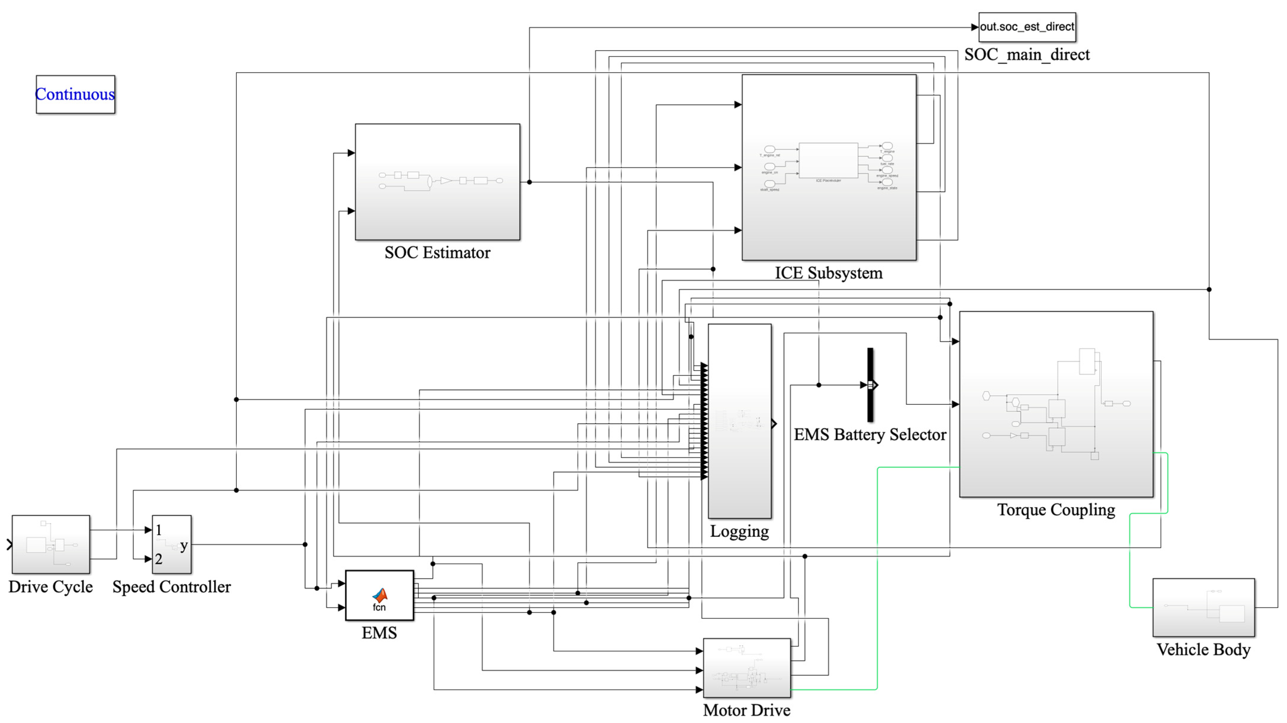
A control-oriented model of a parallel hybrid electric vehicle in which tractive effort is generated through the combined operation of an electric motor and an internal combustion engine was considered in this study. The model was implemented in MATLAB/Simulink and includes a reference speed profile source, a speed control loop, an energy management system, an electric traction subsystem with a battery and a DC motor, a simplified internal combustion engine model, a torque summation unit and a longitudinal vehicle dynamics model (
Figure 1).
The prescribed driving cycle defines the reference speed , which is compared with the actual vehicle speed . Based on the resulting tracking error, the PID controller generates a control signal interpreted as a request for traction or braking torque. The energy management system then determines the share of the requested torque to be supplied by the electric drive, as well as the conditions for internal combustion engine engagement and battery charge-sustaining operation. The resulting total torque is transmitted to the vehicle model, which determines the actual vehicle speed and closes the feedback loop. The selected structure is sufficiently detailed to analyze the interaction between the speed control loop, energy management system, electric subsystem and thermal power unit. At the same time, it avoids an excessive physical description of internal processes in individual components. This makes it suitable for investigating control patterns and the energy behavior of a hybrid electric vehicle.
The speed-tracking error is defined as the difference between the reference and actual vehicle speeds:
The control action is generated using a PID controller, which, in the time domain, is expressed as:
where
,
and
are the proportional, integral and derivative gains, respectively, while
is the filtered error introduced to reduce the sensitivity of the derivative term to high-frequency oscillations.
The filter dynamics are described by:
where
is the filter time constant.
In the frequency domain, the controller transfer function is written as:
where
is the derivative filter coefficient.
The signal
generated by the controller is treated in the model as a generalized traction control request. For subsequent use in the powertrain subsystem, it is separated into acceleration and braking components. This forms the initial demand for traction or regenerative braking, which is then processed by the energy management system using the following laws:
The energy management system distributes torque between the electric motor and the internal combustion engine according to the current traction demand and the battery energy state. The inputs to this block are the requested torque , the estimated battery state of charge and logical indicators related to regenerative braking, traction assistance and the need to maintain energy balance.
In the model, the requested torque is determined from the output of the speed controller:
The internal combustion engine activation logic is defined by the following conditional function:
Here, corresponds to the regenerative braking mode, denotes the need for traction assistance, indicates the need to engage the internal combustion engine due to a reduced battery state of charge and defines the conditions under which vehicle motion can be provided by the electric drive alone.
In the traction assistance mode, the reference torque of the internal combustion engine is calculated as:
where
is the coefficient defining the share of traction demand assigned to the internal combustion engine.
In the low-SoC mode, an increased internal combustion engine torque is generated. This torque accounts for the current traction demand as well as for the need to maintain the system energy balance:
where
is the additional torque associated with charge-sustaining operation, while
is the maximum allowable engine torque.
The electric motor reference torque is defined as:
after which it is limited to the admissible range:
A battery charging current command is generated separately:
where
is the charging current used in charge-sustaining mode. In this way, the energy management system provides coordinated interaction between the electrical and thermal subsystems under different driving conditions.
The electrical part of the model consists of the battery, the power H-bridge and the DC motor. For energy management purposes, the model uses a separate state-of-charge estimator. This makes it possible to consistently account for both the traction motor current and the additional charging channel.
The total current that determines the variation in the state of charge is expressed as:
where
is the traction motor current and
is the charging current in charge-sustaining mode.
The dynamics of the state-of-charge estimator are then described as:
where
is the coefficient that converts current into the relative change in battery charge. The
value is additionally limited to the physically admissible range.
The dynamics of the DC motor are described by the classical system of equations. For the armature circuit, the governing equation is:
where
is the armature inductance,
is the armature resistance,
is the armature current,
is the motor voltage,
is the back-EMF coefficient and
is the rotor angular speed.
The electromagnetic torque of the motor is given by:
where
is the torque constant.
The mechanical dynamics of the rotor are described as:
where
is the rotor moment of inertia,
is the load torque and
is the viscous friction coefficient.
In the control-oriented approximation, the motor voltage is defined as:
where
is the battery voltage and
is the duty cycle generated by the PWM control system.
In this study, the internal combustion engine is represented by a simplified quasi-steady-state model. It is intended to reproduce the engine contribution to tractive effort and fuel consumption without a detailed description of internal thermodynamic processes. The actual engine torque is defined as:
where
is a binary variable describing the engine state.
The engine angular speed is assumed to be proportional to the speed of the common mechanical shaft:
The instantaneous fuel consumption is represented by the simplified relation:
where
is the idle fuel consumption rate,
is the coefficient describing the effect of torque on fuel consumption and
is the normalizing speed.
In the parallel hybrid configuration, the total torque transmitted to the transmission is determined as:
where
is the mechanical braking torque.
Within the analyzed model, the electric motor torque and the internal combustion engine torque are dominant, while mechanical braking has an auxiliary role. The conversion of the total powertrain torque into vehicle translational motion is described using the longitudinal dynamics model. The torque at the driving wheels is given by:
where
is the transmission gear ratio and
is the mechanical transmission efficiency.
The tractive force at the wheel is calculated as:
where
is the wheel radius.
The longitudinal motion of the vehicle is described by:
where
is the equivalent vehicle mass,
is the rolling resistance force,
is the aerodynamic drag and
is the grade resistance component.
The resistance forces are defined using standard relations:
where
is the gravitational acceleration,
is the rolling resistance coefficient,
is the air density,
is the aerodynamic drag coefficient,
is the vehicle frontal area and
is the road grade angle.
The speed-tracking loop uses a PID controller with fixed parameters , , and and a derivative filter coefficient . The controller generates a generalized control signal from the error between the reference and actual vehicle speeds. This signal is then processed by the energy management block, which determines whether the electric drive, the internal combustion engine and the battery charge-sustaining mode should be activated. In the simulation experiments, the energy management logic used fixed parameters: lower and upper state-of-charge thresholds and , respectively; torque demand thresholds and ; the auxiliary internal combustion engine torque coefficient and the additional charging torque . The relatively narrow SoC window was selected as a charge-sustaining calibration intended to trigger early engine support and thereby limit deep battery depletion during long repeated-cycle simulations. In this study, these thresholds should be interpreted as model calibration parameters for comparative analysis rather than as universally optimal HEV set points.
To assess whether the principal findings are contingent on a single arbitrary controller setting, an additional local sensitivity study was conducted around the baseline calibration. For the PID controller, one-at-a-time variations of ±20% were applied to the proportional, integral and derivative gains while preserving the remaining terms at their baseline values. Because the most demanding operating conditions were observed for the repeated US06 cycle, the sensitivity analysis was focused on this scenario. In parallel, the supervisory energy-management parameters were perturbed by varying the lower and upper SoC thresholds and the additional engine charging torque. This procedure was intended to verify whether the qualitative conclusions regarding cycle-dependent control degradation and energy-consumption growth remain stable under moderate retuning of the low-level speed controller and supervisory layer.
The simulation was performed using the standardized FTP75, HWFET and US06 driving cycles. The selection of standardized driving cycles as the basis for this comparative study is justified by the fact that current research often analyzes the effectiveness of hybrid vehicle energy management under predicted or uncertain driving profiles. Zhang et al. [
21,
22] showed that driving-cycle uncertainty and vehicle–environment interaction can substantially affect optimal energy distribution. Therefore, a fixed set of standardized scenarios was used in this study. This made it possible to specifically assess the influence of driving-cycle characteristics on the dynamic and energy performance of the hybrid electric vehicle under an unchanged control structure. For correct interpretation of the results, each driving cycle was considered as a separate representative operating scenario. The FTP75 cycle was used as a model of urban driving with frequent stops, accelerations and decelerations, that is, with a highly non-uniform speed profile. The HWFET cycle represents highway operation and is characterized by relatively steady motion. Its average speed is 77.68 km/h, the maximum speed is 96.40 km/h and the share of stops is low. By contrast, the US06 cycle represents aggressive vehicle operation. It has an average speed of 77.33 km/h, a maximum speed of 129.23 km/h and a much wider range of accelerations and decelerations, including up to 3.755 m/s
2 during acceleration and down to −3.085 m/s
2 during braking. Although HWFET and US06 have similar average speeds, they differ fundamentally in the dynamic structure of vehicle motion. The former reflects relatively steady highway driving, while the latter imposes much more severe conditions on both the powertrain and the speed control loop. Together with FTP75, these cycles cover three qualitatively different operating modes of a hybrid electric vehicle: urban, highway and highly dynamic driving. Because the durations of HWFET and US06 are considerably shorter than that of FTP75, these cycles were repeated to obtain a duration close to the baseline scenario. This was done to ensure a more consistent comparison of energy-related indicators. As a result, three scenarios were used in this study: FTP75 with a duration of 2500 s, HWFET with a duration of 2295 s and US06 with a duration of 2400 s. This approach avoided a direct comparison of short and long cycles in their original form and made the results more representative in terms of total energy load.
During the simulation, the time datasets of the reference and actual speeds, battery state of charge, electric motor current, battery voltage, energy management mode signal, internal combustion engine engagement signal, charging current command and instantaneous fuel consumption were recorded. To avoid ambiguity in SoC evaluation, the model used a separate external SoC estimator. This estimator served as the main source of information for the energy management system and for subsequent analysis of the results. The distance traveled by the vehicle was determined by numerical integration of the actual vehicle speed, which ensured correct calculation of specific energy indicators.
The quality of speed control was quantified using the root mean square error, mean absolute error, integral absolute error and integral time-weighted absolute error. Energy efficiency was evaluated using the final battery SoC, absolute SoC decrease, specific SoC decrease per kilometer, total fuel consumption, fuel consumption per kilometer and fuel consumption per 100 km. The operating-mode indicators of the hybrid powertrain were also analyzed separately. These included the share of active internal combustion engine operation, the share of time in charge-sustaining mode and the current load of the traction electric drive.
Numerical integration of the system was performed using standard MATLAB/Simulink tools. To ensure stable simulation of long-duration scenarios and to prevent an excessive reduction in the integration step, the maximum calculation step was set to 0.05 s. This setting was selected after a preliminary analysis of model behavior, which showed that overly frequent switching between energy management modes could locally reduce computational efficiency. Therefore, the final experimental configuration used a stabilized low-SoC logic. For , a single mode of active internal combustion engine engagement was maintained without rapid switching between similar submodes. This made it possible to complete all analyzed scenarios correctly over the full simulation interval.
The adopted model is intentionally control-oriented and, therefore, includes several simplifying assumptions. The internal combustion engine is represented by a quasi-static torque and fuel-rate surrogate, without explicit modeling of clutch engagement transients, start–stop delays or gear-shift dynamics. The electrical subsystem includes a battery voltage source and current-based SoC estimator but does not incorporate a thermal derating mechanism or current-limiting logic driven by cell temperature. In addition, the mapping between speed-tracking error and generalized torque request is linearized at the controller output level. These assumptions reduce structural complexity and improve interpretability of the control study. However, they also imply that the model is more suitable for comparative analysis of control trends than for high-fidelity reproduction of fast drivetrain transients. The reported results should, therefore, be read as control- and cycle-sensitive performance indicators of a reduced-order HEV architecture, not as certification-grade predictions of absolute vehicle behavior.
3. Results and Discussion
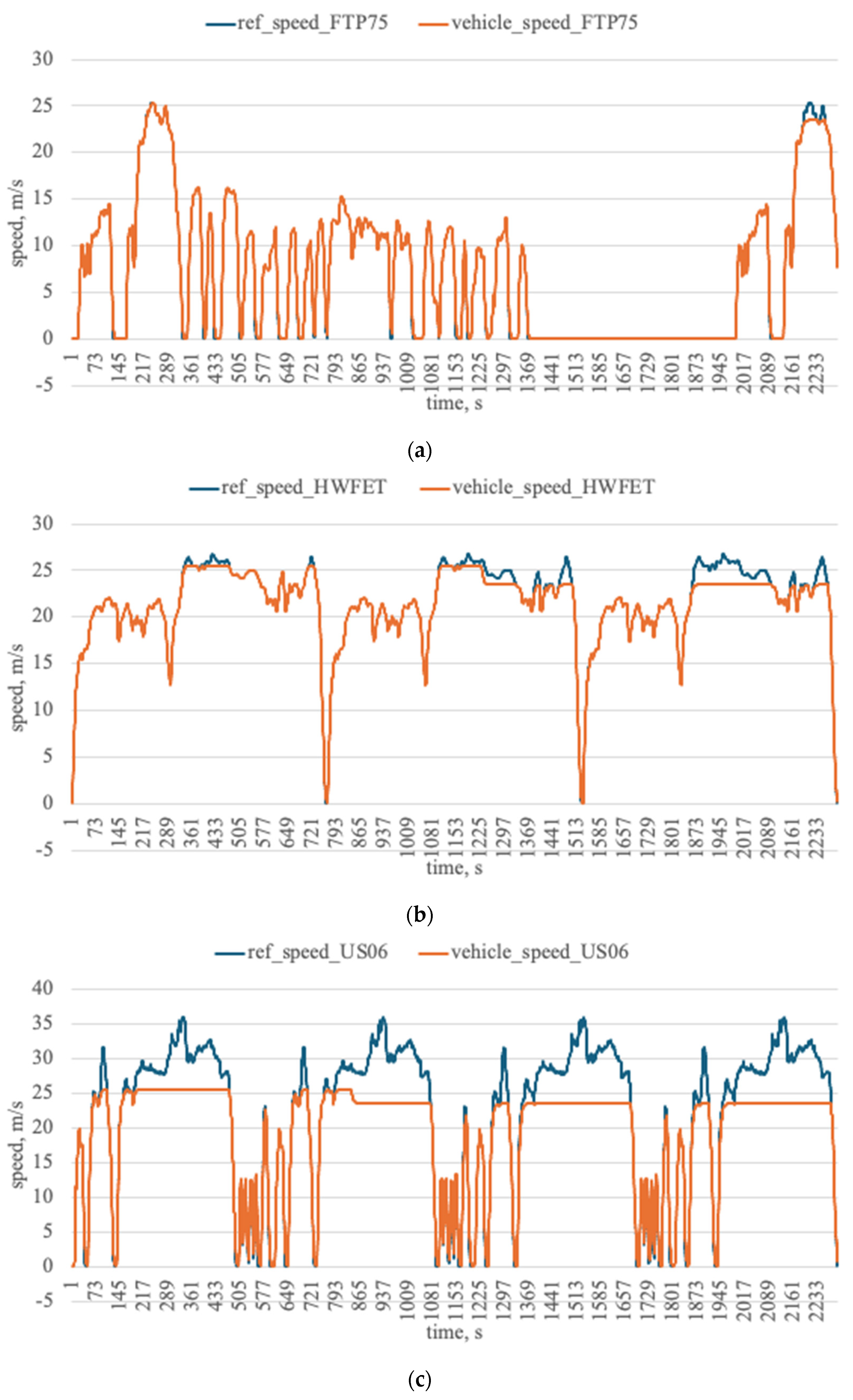
To evaluate the control quality of the hybrid electric vehicle with a PID controller, the simulation results obtained for three standardized driving cycles were analyzed. The comparison was performed using the root mean square error, mean absolute error, integral absolute error and integral time-weighted absolute error (
Figure 2).
The best tracking accuracy was obtained for the FTP75 cycle, where RMSE = 0.2649 and MAE = 0.0669. For the HWFET cycle, the quality of speed tracking deteriorated. RMSE increased to 0.7886, and MAE increased to 0.3604. The least favorable results were obtained for the US06 cycle, with RMSE = 4.5672 and MAE = 3.1959. Thus, the transition from a moderate urban cycle to a highly dynamic aggressive driving mode leads to a sharp decrease in control accuracy. The same trend is confirmed by the integral criteria. For FTP75, the IAE and ITAE values are 167.34 m and
m·s, respectively. For HWFET, they increased to 827.40 m and
m·s, while for US06, they reached 7673.4 m and
m·s. This indicates that as the dynamic severity of the driving cycle increases, the local control error as well as the cumulative deviation from the prescribed speed profile increases over the entire driving interval. Therefore, the selected PID controller tuning is sufficiently effective for FTP75, acceptable for repeated highway driving and clearly insufficient for US06 (
Table 1).
To determine whether the observed deterioration in the US06 scenario is merely a consequence of one PID tuning, a local sensitivity analysis was carried out by varying each gain by ±20% around the baseline setting (Kp = 100, Ki = 50, Kd = 10). The obtained results indicate that the qualitative conclusion is highly robust. Across all tested PID variants, the RMSE in the US06 case remained within 4.567–4.568 m/s, while the specific fuel consumption varied only within 10.293–10.338 L/100 km. The final SoC changed by less than 0.05 percentage points, and the share of internal combustion engine operation varied by less than 0.004. Thus, moderate perturbations of the PID gains do not alter the principal conclusion that a fixed-gain controller is structurally insufficient for highly aggressive driving conditions. This shows that the poor performance in US06 reflects a structural limitation of the fixed-parameter control architecture rather than a single accidental tuning choice. At the same time, this sensitivity study is intentionally local and should not be interpreted as a substitute for global controller optimization over the full HEV operating domain.
A complementary sensitivity analysis was then performed for the supervisory energy-management parameters. In this case, the influence of the SoC window and additional engine charging torque proved to be substantially more pronounced than the influence of moderate PID retuning. For the US06 cycle, the variant with a lower SoC threshold of 80%, an upper SoC threshold of 83%, and an additional charging torque of 0.06 produced the most favorable dynamic-energy compromise among the tested cases, yielding RMSE = 4.298 m/s and a specific fuel consumption of 10.025 L/100 km, albeit with a lower final SoC of 53.008%. By contrast, increasing the charging torque to 0.10 raised the final SoC to 54.045% but worsened the tracking accuracy to 4.847 m/s and increased the specific fuel consumption to 10.620 L/100 km. These results show that the supervisory layer primarily redistributes the trade-off between tracking quality, fuel expenditure and charge maintenance, whereas moderate PID retuning alone does not remove the underlying cycle-dependent limitation of the control system.
To provide a simple non-optimized reference case, an additional rule-based speed controller was tested using the same vehicle, powertrain and energy management structure. In comparison with the fixed-gain PID controller, the rule-based baseline exhibited a substantially poorer cycle-following capability (
Table 2). For FTP75, the RMSE increased from 0.265 m/s to 1.794 m/s, while the traveled distance over the same simulation interval decreased from 17.813 km to 14.833 km. For the repeated US06 cycle, the degradation was even more pronounced: RMSE increased from 4.567 m/s to 9.386 m/s, and the traveled distance decreased from 44.296 km to 33.138 km. Although the comparator showed lower fuel consumption and lower internal combustion engine utilization, this reduction was achieved at the expense of inadequate speed-profile reproduction and reduced transport work. Therefore, the comparison shows that the PID layer reduces tracking error by roughly a factor of 4–7 relative to a simple threshold-based baseline, at the cost of negligible additional fuel consumption.
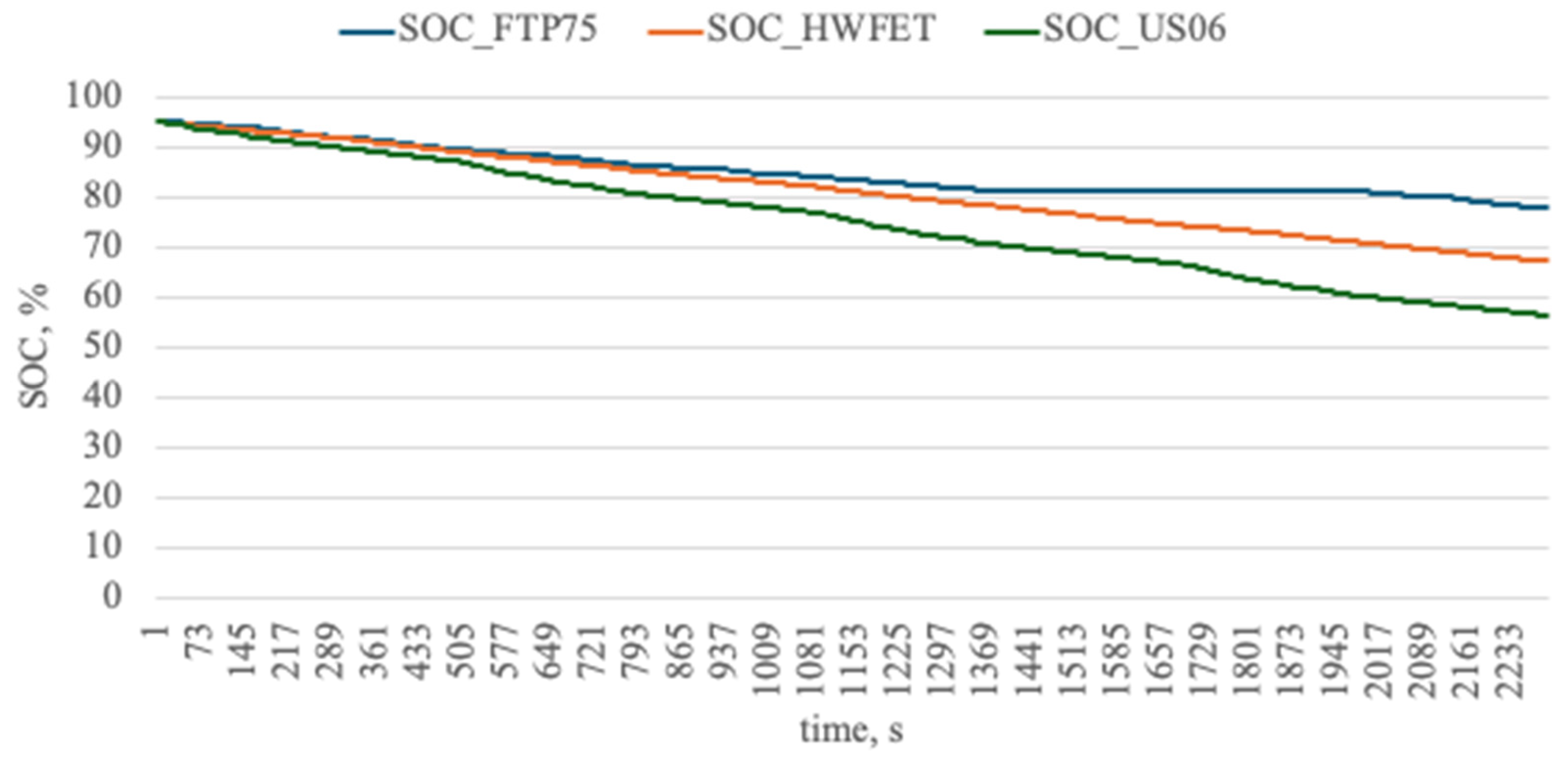
The energy efficiency of the model was evaluated using the variation in the main battery state of charge, total fuel consumption and distance-normalized indicators. Because the durations of the scenarios were artificially aligned by repeating the shorter cycles, while the corresponding transport work remained different, both absolute and specific indicators were used for a correct comparison. For the FTP75 cycle, the decrease in battery SoC is 19.698. For HWFET, it is 28.002, while for US06, it reaches 41.630. In absolute terms, this means that the greatest battery depletion occurs in the aggressive US06 cycle. However, distance normalization provides a more precise interpretation of the results. The specific SoC decrease is 1.1058 per kilometer for FTP75, 0.5750 per kilometer for HWFET and 0.9398 per kilometer for US06. Therefore, in terms of distance traveled, the least intensive use of battery charge occurs in HWFET, whereas FTP75 and US06 are more energy-demanding operating modes (
Figure 3).
Total fuel consumption also depends strongly on the nature of the speed profile. For FTP75, it is 0.8594. For HWFET, it increases to 3.5384, while for US06, it reaches 4.5748. In specific terms, these values correspond to 4.8243, 7.2652 and 10.328 L/100 km, respectively (
Table 3). Therefore, FTP75 is the most favorable cycle in terms of fuel economy, whereas US06 is characterized by the highest specific fuel consumption. This result is expected, as US06 combines high acceleration intensity, substantial peak speeds and a pronounced non-uniformity of vehicle motion, which leads to a considerable increase in hybrid powertrain load.
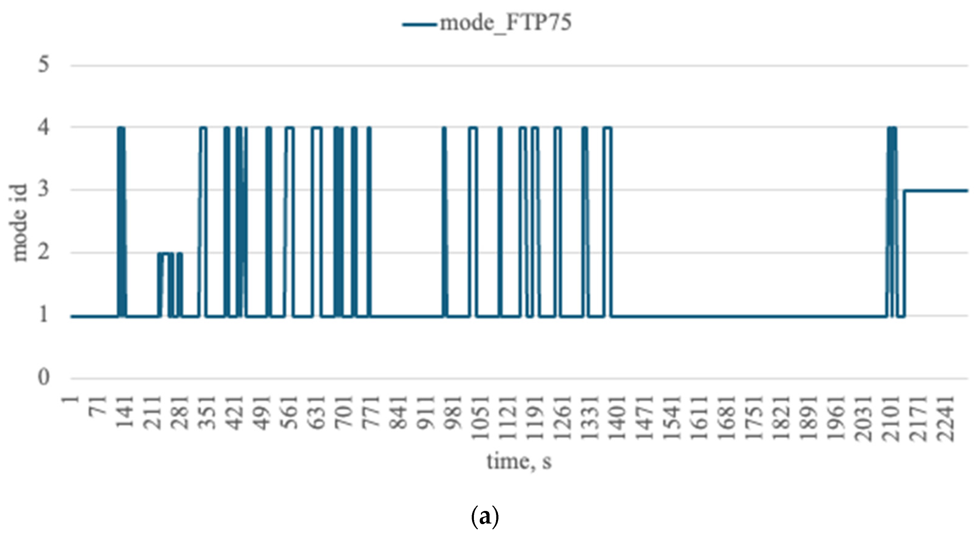
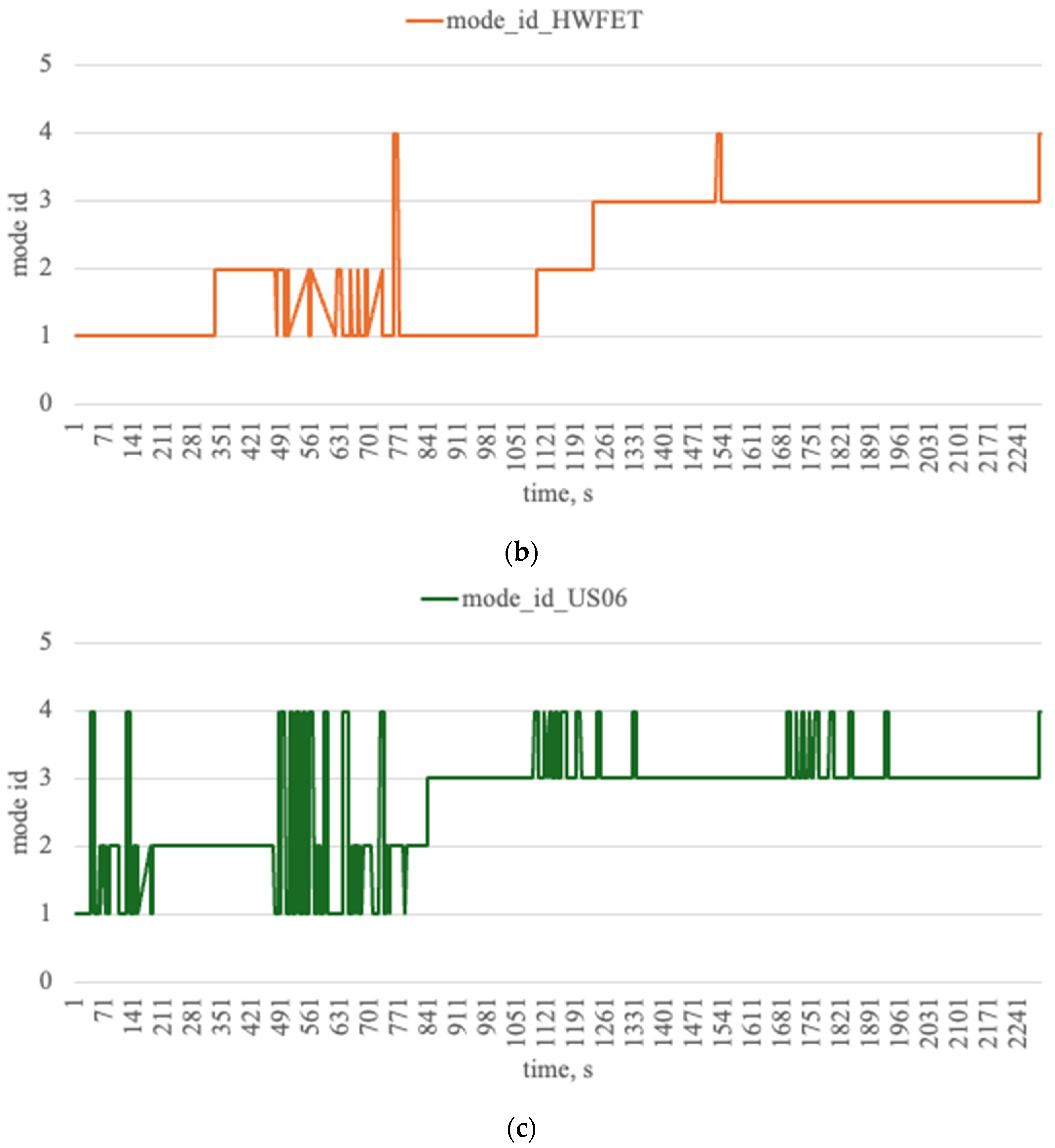
Additional insight into system operation is provided by analyzing the share of time during which the internal combustion engine is active and the share of time spent in charge-sustaining mode. In the analyzed model,
corresponds to electric driving without active internal combustion engine engagement;
denotes combined traction assistance, where part of the load is assigned to the internal combustion engine;
represents the low-SoC mode, with active internal combustion engine contribution and energy balance support; and
corresponds to regenerative braking. For FTP75, the share of active internal combustion engine operation is 0.1536, while the share of time in charge-sustaining mode is 0.1461. For HWFET, these indicators increase to 0.5346 and 0.4358. For US06, they reach 0.6789 and 0.6022, respectively (
Figure 4).
The obtained results show that as the dynamic intensity of the driving cycle increases, both total energy consumption and the role of the thermal subsystem in vehicle propulsion increase. In the FTP75 cycle, the analyzed model operates for a relatively long time without substantial internal combustion engine engagement. In HWFET and especially in US06, the share of engine operation increases. This means that the same PID controller configuration, combined with unchanged energy management logic, produces different powertrain operating structures depending on the type of speed profile. This result is important for interpreting the efficiency of the model. The degradation observed in more aggressive cycles should be associated with the speed-tracking error itself as well as with changes in the internal logic of energy distribution between the electrical and thermal subsystems. Therefore, the driving cycle determines the external quality of vehicle motion as well as the operating-mode architecture of the hybrid system (
Table 4).
To further relate the obtained performance indicators to the intrinsic severity of each driving schedule, an additional window-based analysis was performed using consecutive 60 s segments of the three simulated cycles (
Table 5). For each window, macroscopic descriptors of the speed profile were computed, including mean speed, standard deviation of speed, RMS acceleration, acceleration variability, braking fraction and stop fraction. These descriptors were then correlated with local control and energy indicators. Dynamic non-uniformity of the cycle, not mean speed itself, emerged as the strongest predictor of peak electric-drive loading. In particular, the maximum absolute motor current exhibits very strong positive Spearman rank correlations with the standard deviation of speed (
), mean positive acceleration (
) and RMS acceleration (
). This explains why the US06 cycle, despite having an average speed close to that of HWFET, generates far more severe electric-drive loading.
The engagement of the internal combustion engine is governed by a different set of macro-level drivers. The share of engine operation time shows a strong positive Spearman rank correlation with mean vehicle speed () and a pronounced negative correlation with stop fraction (). The increased reliance on the thermal subsystem in HWFET and especially US06, therefore, reflects the higher sustained speed demand imposed by these cycles rather than poor speed tracking alone. The tracking error itself is likewise cycle-sensitive: RMSE correlates positively with mean speed (), braking fraction () and acceleration variability. The degradation observed under aggressive or high-speed conditions is, therefore, jointly determined by controller limitations and by the statistical structure of the driving cycle itself.
A supplementary multiple-regression check confirmed that the selected macro-scale descriptors explain a substantial part of the observed variation, with R2 = 0.604 for ICE operation share and R2 = 0.322 for the local fuel-use indicator.
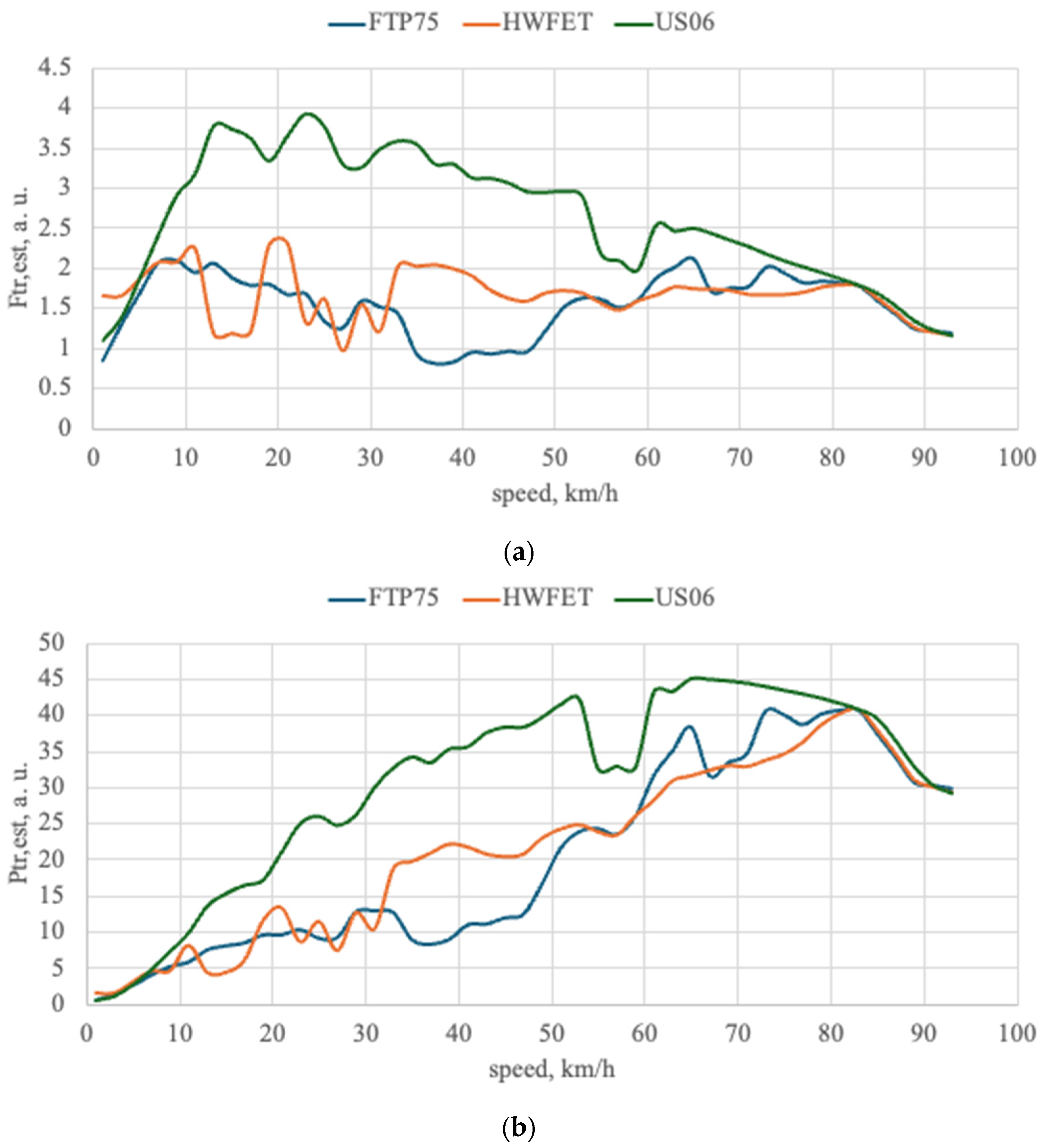
To further explain the differences between the driving cycles, the operational envelopes of tractive force
and tractive power
(
Figure 5) were constructed as functions of vehicle speed. Unlike the nominal traction-speed characteristics of a real vehicle, these curves do not represent the limiting capability of the powertrain under full load. Instead, they describe the operating regions realized during the corresponding driving cycles. The curves were generated using positive traction operating points. For each 2 km/h speed bin, the 90th percentile of the corresponding quantity was calculated and then smoothed.
The analysis of the obtained curves shows that the US06 cycle produces the highest tractive load in the low- and medium-speed ranges. This is consistent with the previously obtained results for the US06 cycle. The HWFET cycle is characterized by a more uniform tractive power profile, which corresponds to highway driving with fewer sharp transient processes. The FTP75 cycle shows a lower envelope level over most of the speed range. This is associated with its urban driving pattern, where accelerations, braking phases and stops alternate frequently. The convergence of the curves in the high-speed range indicates that the operating modes approach a common load region determined by the powertrain parameters and road-load forces.
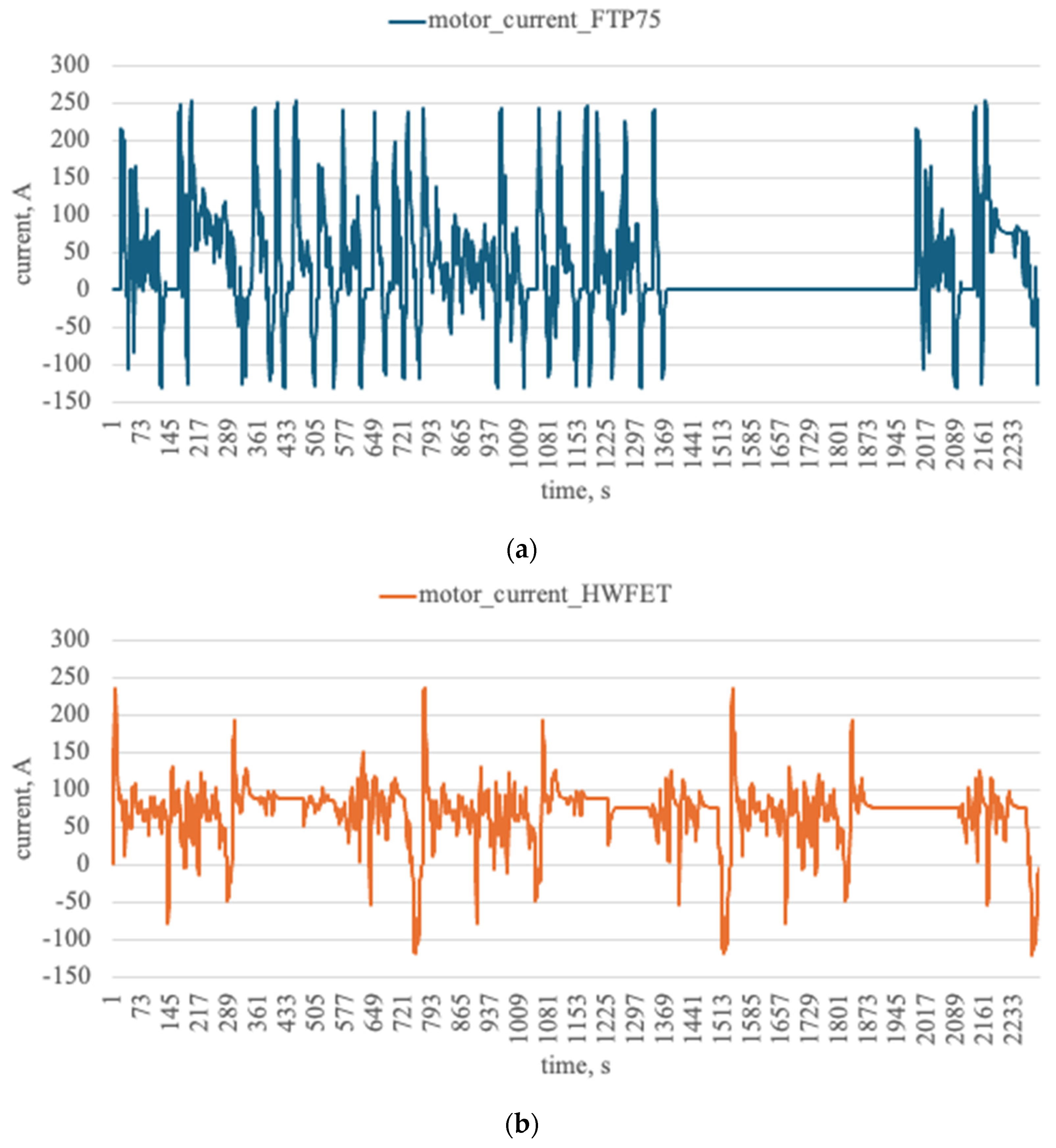
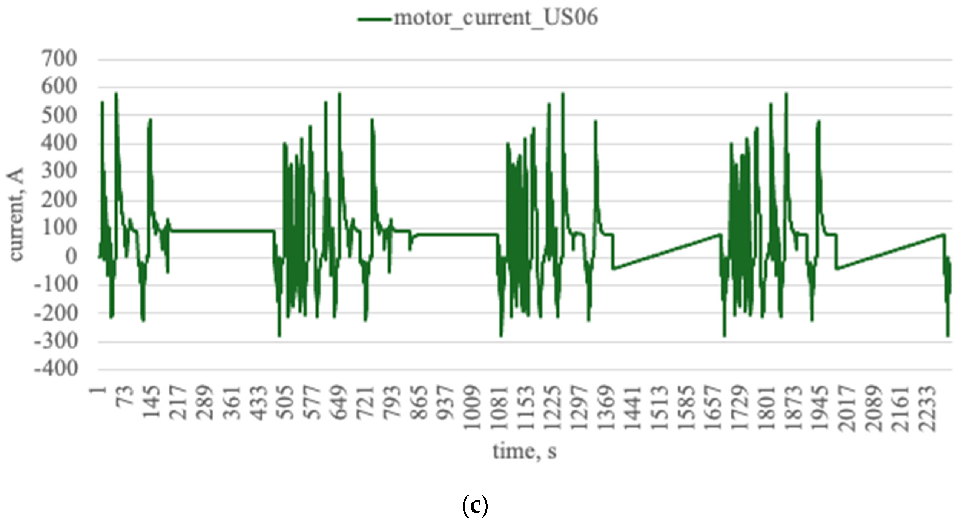
Given the identified differences in the operational tractive load envelopes, the mean and maximum values of traction motor current were additionally analyzed (
Table 6). In the FTP75 cycle, the mean motor current is 48.52 A, and the maximum value is 253.99 A. For HWFET, the mean current increases to 74.93 A, while the maximum value is 235.86 A. The US06 cycle imposes the highest load, with a mean motor current of 105.31 A and a maximum value of 580.91 A (
Figure 6).
From an engineering perspective, this means that the aggressive driving cycle is the most critical for the speed controller as well as for the power electronics, electric motor and power supply components. High peak and mean current values indicate a substantial increase in electrical loading. This should be considered when assessing the suitability of a given control law for real operating conditions. Therefore, limiting the analysis to speed error metrics alone, without considering the current regime of the electric drive, does not allow the efficiency of hybrid vehicle control to be fully evaluated.
The overall results show that the effectiveness of the analyzed hybrid electric vehicle configuration with a PID speed controller is strongly drive-cycle dependent. The FTP75 cycle provides the best combination of speed-tracking accuracy, fuel economy and relatively moderate loading of the energy sources. The HWFET cycle is characterized by poorer dynamic performance and a substantially higher share of internal combustion engine operation. However, when normalized by distance, it demonstrates the lowest battery depletion rate. The US06 cycle is the least favorable for the analyzed configuration, as it is accompanied by a sharp increase in control errors, fuel consumption, thermal subsystem utilization and electrical loading. The results indicate that using the same set of PID controller parameters does not ensure the equally high performance of the hybrid electric vehicle under different standardized driving cycles.
The present study should be interpreted within the limits of a control-oriented modeling framework. First, the internal combustion engine subsystem is described by a reduced quasi-static surrogate and, therefore, does not reproduce clutch-mediated launch transients, start–stop delays or shift-event dynamics. Second, the battery model does not include electrothermal coupling or protective current derating. The reported current peaks, therefore, indicate relative electrical loading between cases, not the absolute admissibility of cell-level currents. For the same reason, the reported fuel-use and battery depletion indicators should be interpreted primarily as comparative measures of control- and cycle-dependent behavior rather than as exact real-world energy predictions. Third, the torque request is generated from a fixed-gain linear PID law, whereas the actual mapping between speed error, driver demand and wheel torque in production HEV control systems is typically nonlinear and mode-dependent. Finally, the present analysis is limited to standardized cycles and a reduced set of supervisory parameter variations. Future work should, therefore, focus on adaptive or gain-scheduled speed control, higher-fidelity actuator and engine transient modeling, explicit electrothermal constraints and validation under measured real-world driving trajectories.





 ,
,