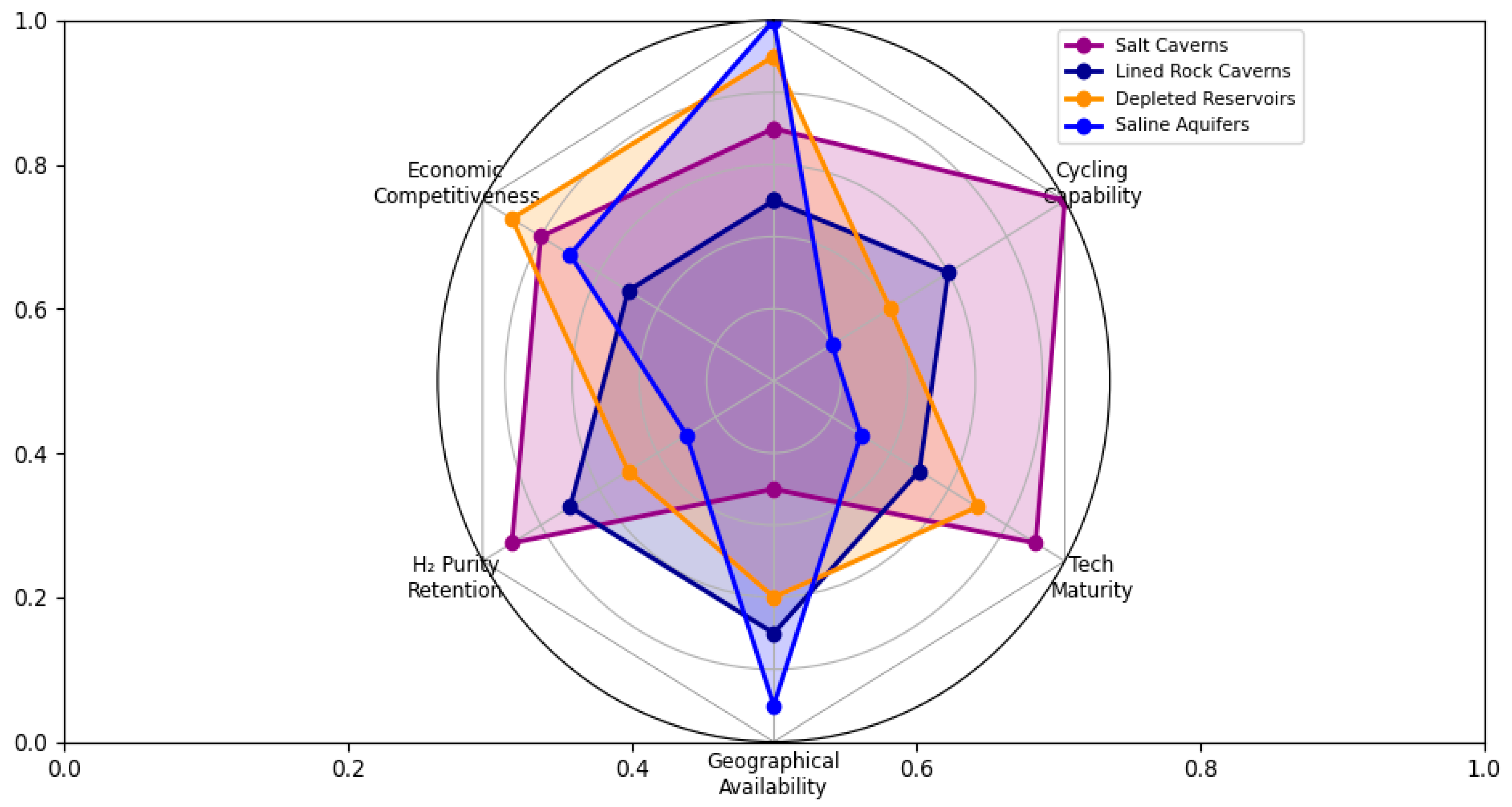
There has been a lot of recent research on UHS in depleted gas and oil reserves, aquifers, and man-made underground spaces, such as salt and rock caverns. These geological formations have certain good traits, such as (i) being gas-tight enough, (ii) having walls that are much thicker than those of regular storage tanks, and (iii) being very far underground, which makes them safer.
2.1. Salt Caverns
Salt caverns are optimal for extensive, long-term storage to equilibrate fluctuating supply and demand as decarbonization and the implementation of renewable energy accelerate. Salt caverns leverage the near-zero permeability, self-healing characteristics, and chemical inertness of rock salt, in contrast to surface H
2 storage tanks or porous formations like aquifers or depleted oil and gas reservoirs [
17].
Salt caverns are currently the most mature and commercially deployed UHS method, particularly suited for frequent cycling and high-purity hydrogen storage. Salt caverns have excellent storage and scalability. Over 100,000 to over a million cubic meters can be stored in caves at depths of 500 to 2000 m. Extremely high-pressure H
2 storage, usually between 20 and 30 megapascals (MPa), is made possible by these depths and volumes [
18]. An example of a project that has demonstrated long-term dependability is the Clemens Dome in the United States, which has achieved an H
2 usability rate of 99.8% and over 60,000 pressure cycles without failure [
17]. Salt caverns function like large “energy batteries,” storing excess renewable energy during peak times and releasing H
2 when demand increases, or output decreases [
19,
20].
Table 4 presents the key characteristics, advantages, and limitations of using salt caverns for underground hydrogen storage (UHS). It covers aspects such as geological integrity, storage capacity, performance, hydrogen purity, economic factors, and environmental impact. The table highlights why salt caverns are a viable and efficient option for large-scale hydrogen storage, while also outlining their geographic and operational constraints.
Salt cavern storage has also been demonstrated to be cost-effective, particularly in terms of capital expenditure (CAPEX) and the levelized cost of H
2 storage (LCOHS). Since solution mining, a well-established and affordable building technology, costs
$1–2 per cubic meter, salt caverns are better for the economy [
24]. Hydrogen storage in salt caverns is 80–90% cheaper than above-ground tanks. Salt cavern UHS costs
$0.39–
$2.41 per kg of H
2, while surface tanks cost
$5.00–
$15.00 [
17,
25]. The geological integrity of salt reduces leakage and monitoring costs, cutting operational costs. The U.S. Clemens project cut development costs by 40% by merging H
2 storage with natural gas salt cavern infrastructure [
26]. This kind of cost-effectiveness makes it more likely that salt cavern systems can be used on a large scale, especially in areas with salt domes or bedded salt formations.
Salt caves have proven more effective than other types of storage media in changing conditions. For instance, the U.S. Advanced Clean Energy Storage (ACES) project in Utah completed 15 successful injection/extraction cycles with a leakage rate of less than 0.08% per cycle, which is the industry standard [
27,
28]. The pressure maintenance methods are performed for the German Teesside projects instead of cushion gas [
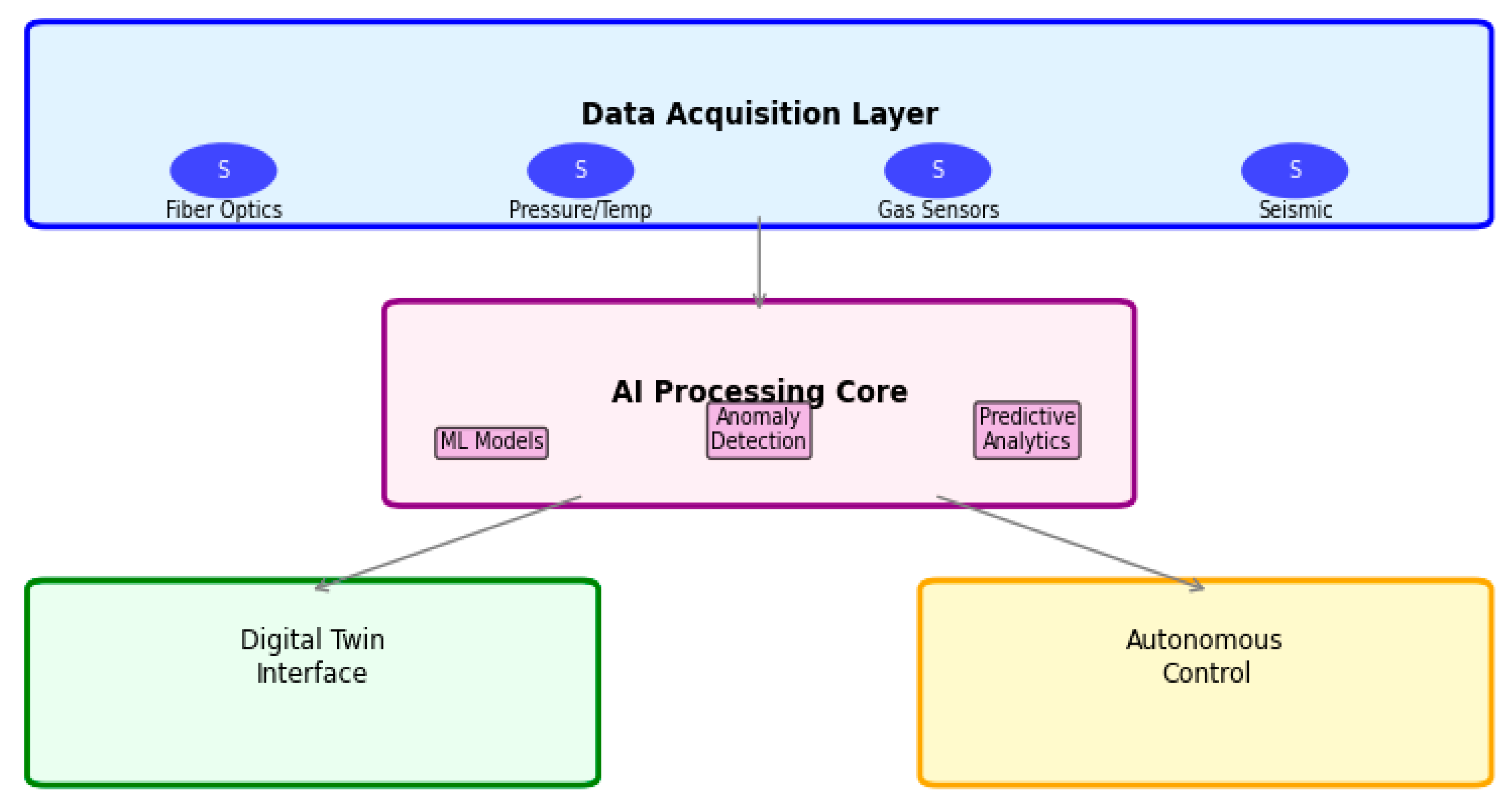
29]. Fiber-optic sensor technologies are also being integrated into wellbores to monitor the structure in real-time and detect leaks early, adding layers of redundancy and diagnostic knowledge [
30].
Salt caverns offer superior operational flexibility, with rapid injection and withdrawal capabilities ideal for balancing short-term energy fluctuations [
31]. In contrast, the injection and production rates are limited in the aquifers and depleted oil and gas fields because of discrepancies in rock permeability and fluid pressure. Salt caverns serve dual functions for long-term seasonal storage and short-term grid stability [
32]. Additionally, because salt caverns maintain H
2’s purity during storage, there is no need for complex and expensive purification methods when it is retrieved. This makes operations easier and reduces the cost of downstream processing [
27].
Salt cavern storage represents the most technologically mature UHS option, benefiting from decades of operational heritage in natural gas and town gas storage. Proven applications include the pioneering Clemens Dome facility in the USA, which has successfully undergone over 60,000 pressure cycles with 99.8% hydrogen recovery, the large-scale Advanced Clean Energy Storage (ACES) project in Utah targeting 1.5 TWh of green hydrogen storage, and active European pilots such as HyCAVmobil in Germany and the Teesside project in the UK, which integrate storage into regional hydrogen hubs. Economically, salt caverns offer a highly competitive levelized cost of hydrogen storage (LCOHS), driven by capital expenditures for cavern leaching and well completion, operational costs for compression and monitoring, and significant cost-saving potential through retrofitting existing natural gas cavern infrastructure, reducing development costs by up to 40%. Nevertheless, key challenges remain, including geographical limitations to regions with suitable salt deposits, long-term stability concerns related to cavern creep and volume loss, sustainable management of water use and brine disposal, especially in arid areas, and the need to adapt existing natural gas storage regulations to address hydrogen’s higher diffusivity and embrittlement risks.
Solution mining requires a significant amount of water, which poses a sustainability issue in arid regions. The long-term carbon reductions and strategic energy security these systems provide may make them valuable. Improved water management and safe brine disposal may inspire innovative salt cavern designs and operations [
33].
Salt caverns are a cleaner choice for storing things than surface tanks or fossil-based storage options from a broader environmental perspective. Salt caverns are a suitable choice for energy infrastructure sensitive to climate change because they leak only small amounts of water, less than 0.05% per year in some U.S. projects. The U.S. Department of Energy’s 2024 Hydrogen Strategy and the European Union’s REPowerEU plan both highlight the importance of underground storage for the growth of the H
2 ecosystem [
27]. The essay, on the other hand, discusses several technological and regulatory problems.
In salt caves with layers of mudstone or gypsum, permeability goes up by several orders of magnitude, which makes leaks worse. If nothing is done, rocks having a permeability of more than 1 × 10
−17 m
2 can lose 45% of their H
2 over 30 years [
34]. Over time, salt rocks slowly change shape, which can cause the cavern to shrink and the structure to become less stable. Some salt caverns lose 1–3.5% of their volume during the course of 30 years [
35]. There are rules for storing natural gas, but H
2 needs its own risk assessment and material compatibility criteria because it is lighter, more diffusive, and chemically active [
36]. Highlighting successful programs like ACES in the U.S. and HyCAVmobil in Germany can help change how people perceive them and promote policy advocacy [
37].
Table 5 outlines the distinct technical and operational aspects of using salt caverns for H
2 storage. It highlights key features such as their formation, impermeability, storage capacity, and cycle flexibility, along with current global projects and industrial applications. The table also notes specific challenges like hydrogen’s low density and the need for compression, while emphasizing the overall suitability of salt caverns for large-scale underground hydrogen storage.
2.2. Lined Rock Caverns and Abandoned Mines
As part of the global effort to create scalable, safe, and cost-effective storage systems that can balance the intermittency of renewable energy sources and ensure a stable H
2 supply for industry and transport, rock caverns and abandoned mines are emerging as viable underground storage sites (UHS) [
46]. Both methods are based on the larger idea of subterranean energy storage, which has worked well for natural gas, oil, and compressed air. However, they need to be carefully re-evaluated for H
2, which is a small, diffusive, and reactive molecule.
Table 6 presents a comparative analysis of Lined Rock Caverns (LRCs) and Abandoned Mines for underground hydrogen storage (UHS). It examines key aspects, such as definition, advantages, challenges, safety, cyclic capability, environmental risks, and technology readiness.
Table 6.
Comparative analysis of Lined Rock Caverns and Abandoned Mines for UHS [
38,
39,
46,
47].
Table 6.
Comparative analysis of Lined Rock Caverns and Abandoned Mines for UHS [
38,
39,
46,
47].
| Aspect | Lined Rock Caverns (LRCs) | Abandoned Mines |
|---|
| Definition | Purpose-built excavations in competent rock, sealed with a multi-layer liner. | Pre-existing, often irregular voids from mining activities, requiring significant retrofit. |
| Primary Advantage | Site selection flexibility independent of specific geology; can be sized as needed. | Low initial excavation cost; potential for rapid deployment using existing voids. |
| Key Challenges | Very high construction cost ($10–20/m3); hydrogen embrittlement of liners; long-term sealing integrity. | Poor and unknown geotechnical stability; complex sealing needs; potential groundwater contamination and legacy pollutants. |
| Safety & Integrity | Dependent on liner performance and rock mass quality. Risk of progressive micro-leakage. | Inherently high risk due to unknown fractures, connections to the surface, and potential for collapse. |
| Cyclic Capability | Moderate. Limited by liner material fatigue and thermal-mechanical stresses. | Very low. Unsuitable for frequent pressure cycling due to structural instability. |
| Environmental Risk | Controlled during construction. Risk linked to liner failure. | High. Risks include acid mine drainage, groundwater chemistry alteration, and surface subsidence. |
| Technology Readiness | Pilot stage (e.g., HyBRIT). Proven for compressed air (CAES), not yet for H2. | Conceptual/Pre-feasibility stage. Considered high-risk and not recommended for large-scale H2. |
On the other hand, abandoned mines are human-made voids left over from prior mining activities. They are often uneven, damaged, and connected to groundwater systems. A thorough analysis of these two storage options, capacity, safety, ease of use, and environmental impact, indicates that engineered rock caverns can be technically viable for H
2 storage to some extent. Still, they remain limited by sealing and cost constraints [
48,
49]. On the other hand, abandoned mines, despite their apparent economic benefits and existing void volume, have ongoing structural, environmental, and operational risks that make them unsuitable for safe, large-scale H
2 containment.
When it comes to system capacity, rock caves can store a modest to high amount of H
2, depending on geology, excavation design, and pressurization methods. Compressed air or oil storage systems in Scandinavia, for example, can hold between 50,000 and 1,000,000 cubic meters. This means they can store tens to hundreds of gigawatt-hours of energy at pressures between 5 and 15 MPa [
50]. The main benefit of rock caverns is that they can be designed in many different ways. However, rock caverns are not very good at storing H
2 because they require artificial sealing systems, such as concrete or polymer linings, to prevent gas from leaking through the common microfractures in most crystalline rocks [
51,
52]. So, even if a rock cavern may have a large theoretical volumetric capacity, its practical H
2 capacity, which is the amount that can be safely stored for long periods of time without losing a lot of it, is lower. This limitation is exacerbated in cyclic storage systems, where fluctuations in pressure and temperature cause sealing materials to wear out and microcracks to spread. So, even though rock caverns could theoretically hold a lot of H
2, their actual storage efficiency depends not on the size of the cavity, but on how well their sealing methods work and how well they are maintained over time [
53,
54].
In contrast, abandoned mines have capacity potential that is not always clear and can change [
55]. The energy density of stored H
2, which is based on both volume and pressure, is still much lower in mines than it is in designed rock caverns or salt formations. Also, the irregular shape of mines makes it hard for pressure to be evenly distributed throughout injection and withdrawal cycles. This creates stress-concentration zones that further reduce usable capacity. Large abandoned mines could be lined with concrete or polymer to make them more stable and better at keeping water out. But these kinds of changes are too expensive and challenging to implement due to the complex access routes and broken infrastructure. Even though abandoned mines may have a lot of space, their actual storage capacity is much smaller. Also, the technical requirements for storing pressurized H
2 make it unsuitable for long-term or high-density storage [
56].
Safety concerns create a more significant distinction between rock caverns and abandoned mines. In designed rock caverns, safety primarily comes from structural integrity, geostatic confinement, and engineered barriers, rather than from natural impermeability [
57]. Hydrogen embrittlement is a well-known problem in steels, cements, and some polymer liners. It is a significant problem because H
2 molecules can enter the microstructures of metals or cementitious materials, weakening mechanical connections over time. Studies in laboratories, notably those from German H
2 storage research programs, show that keeping material permeability below 10
−19 m
2 is essential for technical tightness [
58]. However, in the real world, rock-cement systems often exceed this level after thermal and mechanical cycling.
Additionally, crystalline rocks do not self-heal like halite formations in salt caverns do. Once a fracture starts, it tends to spread with repeated changes in tension. As a result, the sealing efficiency slowly decreases, and the likelihood of H
2 leakage increases over time [
59].
Nevertheless, abandoned mines are inherently dangerous places to store H
2. The primary safety threats come from geological degradation, unregulated paths to the surface, and leftover pollutants or reactive elements from previous mining operations. Most abandoned mines have groundwater systems running through them. Because H
2 can catch fire easily (4–75% in air) and requires very little energy to ignite, even small leaks could pose a serious safety risk. The possibility of H
2-oxygen explosions in mine voids with leftover air or oxygenated groundwater should not be ignored, especially in shallow or inadequately ventilated mines [
60,
61].
The fact that purpose-built rock caverns are easier to utilize and work with makes them even better than repurposed abandoned mines. But the exorbitant cost of excavation and lining, which can range from USD 10 to 20 per cubic meter of storage space, makes them less practical than salt caverns. Also, rock caverns are relatively stable, but they do not have the self-sealing characteristic of salt; therefore, liners and wellheads need to be checked and maintained regularly [
62,
63]. However, rock caves can be good places to store H
2 for the medium to long term if they are built for seasonal or strategic reserves rather than for daily cycling [
64].
On the other hand, it is tough to safely or efficiently run abandoned mines [
39,
65]. Even though reusing existing voids is a good idea since it lowers the cost of initial excavation, the total cost of sealing, monitoring, and risk reduction is often more than building new, purpose-built storage facilities [
66]. So, from a practical and economic perspective, abandoned mines are not suitable for use because they are challenging to operate, perform poorly, and incur high long-term maintenance costs [
67]. This means they should not be part of a national H
2 infrastructure unless they are used under exact, regulated pilot conditions [
68].
Table 7 demonstrates the distinct features of rock caverns and abandoned mines for hydrogen storage, focusing on their formation, construction, and operational characteristics. It describes the engineering requirements such as liners, drainage systems, and pressure management, as well as their current applications, including the HyBRIT pilot project in Sweden.
Table 7 also highlights the advantages of Lined Rock Cavern (LRC) technology in terms of flexibility, pressure handling, and suitability for dynamic hydrogen storage.
2.3. Depleted Reservoirs
The repurposing of end-of-life oil and gas fields for hydrogen storage, leveraging existing wells, data, and infrastructure for low capital expenditure and a levelized cost of storage around
$1.23/kg H
2, demonstrates high technical readiness supported by pilot projects in locations like the UK, Austria, and the USA, drawing an analogy to natural gas storage. However, this approach faces specific challenges, including hydrogen interactions with brine and residual hydrocarbons, microbial consumption, gravity override and mixing issues, and concerns over caprock integrity due to hydrogen’s smaller molecule size, all of which are critical considerations outlined alongside storage capacity and infrastructure advantages in its characteristic profile [
69].
Hydrocarbon reservoirs containing oil or gas are geological formations that have undergone multiple stages of diagenesis, including source rock development, migration, and the passage of time, to function as storage for hydrocarbons. Typically, these reservoirs are covered by an impermeable layer, often aquifer-supported from the bottom or edges. When a gas field nears the end of its productive phase, it is commonly converted into a gas storage facility. The depletion of a gas reservoir, either already depleted or nearing depletion, is characterized by low pressure and high-water saturation in the region once occupied by gas, owing to aquifer water displacement. Consequently, the gas saturation behind the waterfront varies from minimal, corresponding to residual gas saturation near the initial gas/water contact, to maximal, representing gas saturation near the gas/water contact [
70]. A depleted gas reservoir can be conceptualized as an aquifer (geological trap) segment with minimal water in the pores, primarily occupied by trapped gas [
71].
Table 8 presents the key characteristics, benefits, and challenges of using depleted reservoirs for underground hydrogen storage (UHS). It highlights their large storage capacity, proven geological integrity, and cost advantages due to existing infrastructure.
Pore volume, permeability, residual fluid saturation, and cushion-working gas interactions determine subsurface H
2 storage capacity in depleted reservoirs. Both studies show that depleted gas and oil fields are the best large-scale H
2 storage solutions, with GWh to TWh capacities, depleted gas [
8]. The study found that cushion gas accounts for 25–80% of reservoir capacity, with CO
2 serving as both a pressure-support medium and a long-term sequestered phase.
In depleted oil reservoirs, multiphase H
2, brine, and residual oil interactions affect capacity considerably. Hydrogen pore space is reduced by residual oil and water saturations, and hysteresis effects between drainage and imbibition cycles can trap gas in pore throats. Volumetric inefficiencies are mitigated by huge, well-characterized storage capacities and pre-existing infrastructure in many oilfields. After caprock and well integrity testing, many mature oilfields might safely sustain multi-TWh capacities, according to their global reservoir study [
75].
Hydrogen’s small molecular size poses containment challenges but facilitates faster pressure equalization during injection and withdrawal.
Underground hydrogen storage safety includes wellbore integrity, caprock sealing, geomechanical stability, and geochemical or microbiological reaction prevention. Both authors agree that depleted reservoirs, which have safely held hydrocarbons over geological timeframes, allow secure confinement if H
2’s peculiar features are handled [
64].
The primary safety problem in gas reservoirs is gas mixing and gravity override, where buoyant H
2 migrates upward over denser cushion gases, expanding the interfacial area and incurring purity losses. Williams et al. observed that horizontally widespread formations with thin vertical thickness increase mixing. The study also found that natural heterogeneity, like poor vertical permeability layers, reduces gravity override. To avoid up-coning and cross-flow, homogenous formations need operational rate control [
76].
Safety is less important than the integrity of the caprock. Both studies stress the importance of keeping an eye on capillary entrance pressure and fracture thresholds to keep H
2 from leaking through micro-fractures or clay interlayers because its molecular radius is only 0.12 nm. Dilshan et al. [
77] used the Young–Laplace equation for capillary sealing to quantify the stable height of an H
2 column beneath the caprock based on wettability and interfacial tension. Pore throat residual trapping makes it harder to recover, but it also provides a safety buffer. The evaluation found that depleted oil reservoir safety assurance requires hydrodynamic modeling, geochemical analysis, and microbiological risk assessment.
Ease of use refers to the H2 storage system installation, operation, and cycling. Both studies underline that exhausted hydrocarbon resources include wells, pipelines, and geological data from previous production periods, making them highly operationally convenient. Building new salt caverns or aquifers is much more expensive than using this infrastructure.
As the cushion-gas ratio increased, withdrawal efficiency improved, and pressure–volume relationships were predictable and stable. They also showed that injection-well design and rate schedules can balance dispersion and gravity segregation to improve H2 extraction rates.
Understanding fluid–fluid and fluid–rock interactions simplify oil reservoir operations. The scientists noted that H2 storage’s cyclic nature stresses the caprock; therefore, real-time seismic and pressure studies are needed to verify mechanical stability during charge–discharge operations.
Hydrogen manufacturing plants are near oilfields, making deployment easier. Integrating H2 storage into energy infrastructure might simplify logistics and save transportation costs for many refineries and petrochemical plants near mature oilfields. Bibliographic analysis also showed that most research and pilot programs are in regions with well-mapped depleted reservoirs (USA, China, UK, Saudi Arabia, Germany, and Australia), indicating an increasing global preparedness to repurpose hydrocarbon assets for clean-energy storage.
The environmental impact of underground H2 storage includes lifetime emissions, land use, subsurface ecosystem disturbance, and carbon sequestration. Both studies recommend drained reservoirs because they reuse geological formations instead of building new surface infrastructure, reducing ecological footprints.
Williams et al.’s innovative use of CO
2 as a cushion gas combines H
2 energy storage with carbon capture and storage (CCS) [
78]. One geological site can be used as a dual-use decarbonization system, temporarily storing H
2 for renewable intermittency and permanently storing CO
2 in the reservoir’s bottom strata (depleted gas). The simulations show that this configuration improves H
2 storage efficiency and reduces greenhouse gas emissions by immobilizing large amounts of CO
2. If structural and caprock seals are intact, the CO
2 leakage risk is small as it remains immobile below the H
2 zone.
Chemical and microbiological processes complicate the environmental safety of oil-bearing formations. Redox changes caused by H2 injection can dissolve or precipitate minerals, releasing trace metals or changing groundwater chemistry. Most reactions are gradual, and site selection (favoring reservoirs with inert lithologies such as quartzose sandstones) reduces long-term dangers. Hydrogen conversion to methane or H2 sulfide by microbes may cause local pollution. Reduce these processes by sterilizing, controlling injection temperatures, or excluding CO2 when not necessary.
From a systems perspective, both studies see UHS as crucial to large-scale renewable integration. Excess wind or solar electricity can be stored as H
2 and released during demand peaks to reduce the energy system’s carbon footprint. Ali et al. [
79] add that reusing exhausted fields reduces surface disturbance, avoids drilling footprints, and uses existing monitoring wells for environmental surveillance. Standardized subsurface H
2 regulations are needed to ensure environmental compliance and minimize unforeseen interactions with neighboring aquifers.
2.4. Aquifers
Hydrogen is an integral part of decarbonized energy networks since it can be used in many ways and has a high energy density per mass. For large-scale H2 energy storage, we need safe, cheap, and eco-friendly ways to store it. Salt caverns, exhausted hydrocarbon deposits, and saline aquifers are suitable for the environment and cost-effective, especially when there are not many alternative formations around. Saline aquifers are huge, have a lot of pore volume, and have been studied for decades for use in natural gas storage and carbon capture and storage (CCS) projects. They can provide geological, hydrodynamic, and operational information for H2 storage.
Aquifers are made of porous, permeable sedimentary rocks soaked with saline water and covered by impermeable layers. Hydrogen injection displaces brine and fills pore spaces as free gas. Storage behavior depends on H2–brine displacement, capillary trapping, dissolution, and buoyant migration. Hydrogen has lower density, viscosity, and brine solubility than natural gas, which affects its subsurface flow and recovery efficiency. In aquifer models, H2 recovery factors reach 78%, with a potential global energy efficiency of 40% (electricity-to-H2-to-electricity).
Big aquifers can store enough for the nation. For example, Canada’s Keg River Aquifer can store 3.24 Mt H
2 (~2.3 EJ), meeting its national grid’s seasonal energy needs. Aquifers are the most accessible and environmentally friendly choice for large-scale H
2 storage since they are widespread and generally near renewable power sites [
80].
Salt caves are far smaller than saline aquifers, which may store several times more. For grid-scale and seasonal applications, their pore volume, geological stability, and area allow multi-terawatt-hour energy storage. Formation depth, porosity, permeability, and caprock integrity affect storage. Sedimentary basins worldwide, including North America, Europe, and Asia, include thick aquifers appropriate for this use [
81].
Recoverable H
2 makes about 20–50% of the injected gas, while the rest maintains reservoir pressure as cushion gas. Aquifers may need 80% more cushion gas than depleted reservoirs, requiring a significant but reasonable capital expenditure. Injection pressures, caprock thresholds, and migration paths must be determined by numerical modeling and site characterization.
Table 9 shows the key characteristics, advantages, and limitations of using saline aquifers for underground hydrogen storage (UHS). It emphasizes their vast global potential and minimal surface impact but highlights major challenges such as low hydrogen recovery, high cushion gas requirements, and uncertain geological sealing.
With vast global potential and proximity to renewable hubs, saline aquifers offer scalable, long-duration hydrogen storage, despite challenges in recovery and site uncertainty.
Safety is key to aquifer storage. The best aquifers are tectonically stable, far away from fault zones and folded strata, and have enough sealing pressure to keep gas during injection and withdrawal. Evidence from past natural gas and CO2 storage operations shows that well-designed aquifer systems are safe.
Integrated system design, geological screening, material engineering, operational management, and robust monitoring supported by transparent regulations and stakeholder engagement determine safety performance.
After site characterization, saline aquifers are easier to deploy than other large-scale storage solutions. Aquifers use pore spaces, unlike salt caves, which need costly excavation. They can be built alongside renewable energy and H2 hubs using existing gas infrastructure.
Compressed H2 is injected into the aquifer using wells, generating a storage plume like natural gas. A portion is permanently trapped as cushion gas; the rest is seasonal working gas. Reservoir management, optimizing pressure gradients, minimizing viscous fingering and gas channeling, and regulating contamination, determines system performance.
However, aquifer operations require complex modeling, control, and site-specific tweaking. Complex modeling and pilot testing are needed to account for fluid-rock interactions, multiphase flow dynamics, and heterogeneity. These procedures are feasible under regulated settings, according to laboratory research and field analogs like town-gas storage in Germany and France.
Integration potential makes aquifer storage easy to integrate with electrolysis plants, renewable energy sites, and H2 transport networks for seamless conversion and dispatch. The small surface footprint reduces environmental impact.
The greenest subterranean H2 storage method is a saline aquifer. It does not displace freshwater or dispose of brine like some salt caverns. Aquifers are deep below potable water zones, so maintaining sealing integrity reduces groundwater contamination risk.
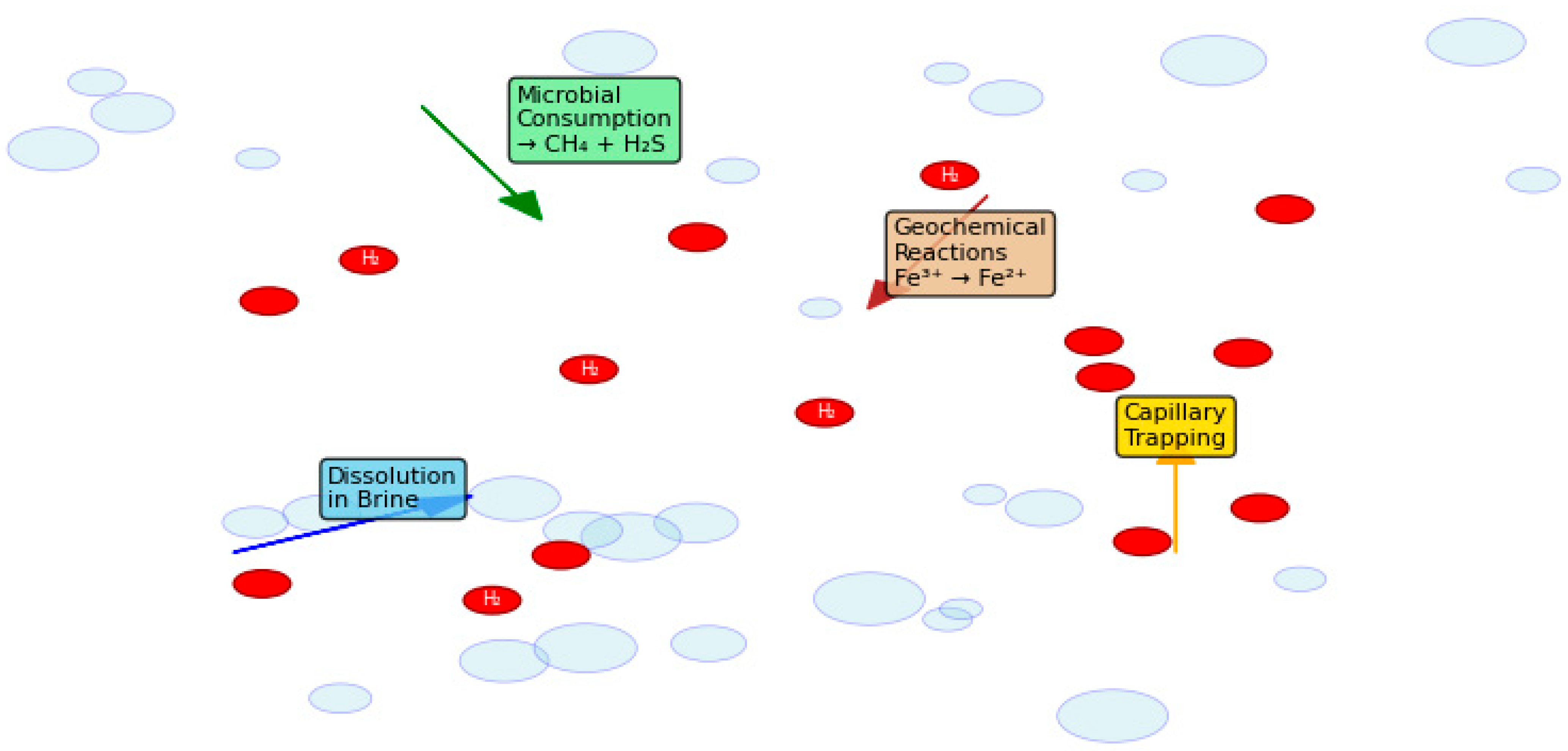
Since H
2 is non-toxic, modest leaks offer little ecological risk, but its flammability requires containment. Indirect impacts from injection pressures may include subsurface microbial changes, mineral changes, or modest seismic reactions, recognized from CO
2 storage analogs, as shown in
Figure 1. Comprehensive risk evaluations and environmental monitoring are required for public acceptance, say the authors.
Large-scale H2 storage helps decarbonize the electricity system, promoting environmental sustainability. Aquifer storage buffers intermittent renewables, lowering fossil-fuel peaker plants and ensuring clean power. Lifecycle analyses show that H2 storage in aquifers has a much lower environmental impact than batteries or compressed air.
Public perception is a key social and environmental aspect. Transparency regarding safety, environmental preservation, and community benefits builds trust. Participatory governance—involving local stakeholders in site selection and oversight—can reduce resistance and speed project rollout.
Economically, aquifer storage is competitive. The average levelized cost of H2 is $1.29 US/kg, second only to depleted oil and gas reservoirs ($1.23 US/kg) and far lower than salt or hard-rock caverns ($1.61–2.77 US/kg). Aquifers. Modest operational expenditures for compression energy, maintenance, and monitoring follow capital-intensive site search and construction. As H2 prices fall, cushion gas expenses, the key capital lock-in, diminish.
Government, industry, and academia should collaborate to improve research, pilot projects, regulatory standards, and social acceptance, according to the study. Scaling aquifer storage internationally and integrating it into H2 supply networks requires continuous monitoring, adaptive management, and legal clarity.
Geological abundance, environmental responsibility, and technical scalability combine in saline aquifer H2 storage. Its system capacity outperforms existing storage technologies, allowing national and continental seasonal energy balancing. Aquifers are essential to the net-zero transition due to their high pore volumes, widespread availability, and proximity to renewable sources.
Mature engineering and regulatory procedures make safety challenging but manageable. To reduce the risk of CO2 and natural gas storage, you can use site-specific geological characterization, sealing integrity-based caprock selection, corrosion-resistant materials, and extensive monitoring networks based on decades of expertise. Design, operational optimization, and surveillance can keep an eye on chemical reactions, H2 embrittlement, and leaks, as well as microbial consumption. The safety of H2 depends on the surface and geological systems.
Using current skills and infrastructure simplifies utilization. Mature drilling, compression, and pipeline technology need only minor H2 adaptation. Flexible operational cycles allow seasonal and short-term storage and fast grid stabilization response times. Regional H2 hubs with renewable electricity and industrial customers are possible with modular aquifer storage.
Sustainability and low environmental impact are supported by aquifer storage. The deep geological framework keeps H2 separate from biospheric processes and lowers environmental stress by stopping brine discharge and surface disturbance. More usage of renewable energy sources indirectly lowers greenhouse gas emissions, air pollution, and the use of resources. Keeping an eye on the environment makes sure that it stays safe for a long time and for the ecology.
Saline aquifers are the backbone of the global H2 economy because they combine capacity, safety, utility, and care for the environment. Even if there are rules, high cushion gas costs, and gaps in subsurface microbiology, research and pilot projects are filling them. Aquifer H2 storage offers a technologically and ecologically sound means to store energy securely, large-scale, and sustainably as nations decarbonize.
The study concluded that saline aquifers are the most fantastic geological medium for long-term H2 storage since they can hold a lot of H2, are safe for the environment, are easy to work with, and are cheap. If they are studied, regulated, and used by the community, their use could speed up the world’s move to a carbon-neutral energy system.
The storage concept is based on the use of deep, porous, saline-saturated rock formations as the subsurface medium for hydrogen storage, where gas is injected and withdrawn through wells in a manner analogous to other underground storage technologies. These formations are characterized by a vast global storage potential; however, they require a large volume of cushion gas to maintain pressure and deliverability, and they are associated with significant geological uncertainty due to heterogeneity in rock properties. In terms of technological maturity, this option has the lowest technology readiness level, with development largely confined to numerical simulations and laboratory-scale experiments, such as those conducted under the H2020 “HyUsPRe” project, while knowledge from CO2 and natural gas storage provides useful analogies. Economically, saline aquifer storage benefits from relatively low infrastructure capital expenditure, but the high cost of cushion gas results in substantial capital being locked up, leading to a levelized cost of hydrogen storage of approximately USD 1.29 per kilogram of hydrogen, which is highly site-specific. Key challenges include maximizing the hydrogen recovery factor, managing the complex fluid dynamics of a highly mobile gas, reliably predicting geochemical and microbial interactions within the reservoir, and ensuring robust site characterization and selection.
Accurate assessment of injection potential and assurance of the safety and efficiency of H2 storage depend on evaluating the technological challenges connected to large-scale H2 storage in saline aquifers. Essential factors in aquifer storage include the footprint of injected H2 underground and its retrieval during cyclic injection/recovery processes. Several elements determine effective storage operations: geological formation characteristics, capacity, fluid and hydrogeological qualities, geological interferences, operational conditions, regulatory frameworks, and societal support.
Table 10 illustrates numerous reviews accessible to the public regarding UHS, spanning various perspectives such as geological analysis [
82,
83], microbial behavior [
1,
8], and detailed examinations of hydrodynamics [
8], geomechanics [
84,
85], geochemical interactions [
42], and well integrity [
8]. Despite the comprehensive coverage provided by these reviews, a focused analysis of depleted gas reservoirs and lined rock caverns remains absent.