Review

Multiphysics and Multiscale Modeling of PEM Water Electrolyzers: From Transport Mechanisms to Performance Optimization

School of Intelligent Manufacturing, Huzhou College, Huzhou 313000, China
*
Author to whom correspondence should be addressed.
Energies 2026, 19(10), 2361; https://doi.org/10.3390/en19102361
Submission received: 31 March 2026 / Revised: 26 April 2026 / Accepted: 11 May 2026 / Published: 14 May 2026
(This article belongs to the Section A5: Hydrogen Energy)

Abstract

Proton exchange membrane water electrolysis is a promising technology for large-scale green hydrogen production due to its high efficiency, compact design, and rapid dynamic response. However, its commercialization is strictly limited by high material costs, durability issues, and complex multiphysics coupling within the membrane electrode assembly. This work provides a comprehensive and critical review of key physicochemical processes and advanced predictive modeling approaches for PEMWEs. To capture recent paradigm shifts, we introduce an innovative multi-dimensional classification framework—incorporating spatial resolution, temporal dynamics, and methodological paradigms—to critically evaluate lumped-parameter, continuum, microscale, and multiscale models, explicitly defining their applicability bounds and inherent limitations. The fundamental mechanisms governing electrode kinetics, membrane water transport, and gas–liquid two-phase flow are analyzed, establishing state-of-the-art quantitative benchmarks for microstructural parameters and advanced 3D flow field topologies under high-current-density and high-pressure regimes. Furthermore, we systematically examine model validation rigor, typical prediction errors, and the critical failure of static models in capturing dynamic property shifts during extreme bubble breakthrough. Recent breakthroughs integrating in situ diagnostics, pore-scale simulations, density functional theory, and Physics-Informed Neural Networks are extensively discussed. Future efforts must prioritize mechanical–electrochemical–thermal coupling, transient degradation prognostics, and machine learning-driven predictive digital twin technologies to overcome current empirical limitations and accelerate the gigawatt-scale deployment of PEMWE systems.

1. Introduction

As global energy systems rapidly transition toward deep decarbonization, green hydrogen has attracted widespread attention as an important energy carrier and is considered a key enabling technology for achieving net-zero emissions. Hydrogen possesses high energy density and zero carbon emissions at the point of use, giving it a critical role in future renewable energy systems. Water electrolysis, as a high-purity and clean hydrogen production pathway, can be directly coupled with intermittent renewable power such as wind and solar, making it a pivotal technology for large-scale green hydrogen production. Among various water electrolysis technologies, PEMWE has gained extensive interest from both academia and industry due to its high current density operation, rapid dynamic response, compact system structure, and capability to produce hydrogen at elevated pressure without additional compression [1,2,3].
Despite these significant advantages, the widespread commercial deployment of PEMWEs still faces several key challenges. First, the reliance on high loadings of noble-metal catalysts such as IrO2 and platinum Pt greatly increases system cost and hampers economic viability in large-scale applications [4,5]. Additionally, proton exchange membranes are susceptible to chemical degradation under prolonged high-voltage and high-humidity operating conditions, which adversely affects durability and long-term stability [6]. Moreover, complex multiphysics interactions within the membrane electrode assembly (MEA), including water distribution, gas evolution, and mass transport limitations, can lead to non-uniform local current density distributions and performance losses that accelerate aging [7,8,9,10]. These highly nonlinear coupled phenomena involve electrochemical reactions, proton conduction, fluid flow, and species transport, making it difficult to fully reveal underlying mechanisms through experiments alone.
To address these challenges, numerical modeling has become an indispensable tool for understanding complex behaviors in PEMWEs and for guiding design optimization and performance improvement [11,12]. Multiphysics modeling approaches can systematically describe reaction kinetics, ohmic losses, mass transport limitations, and coupled transport phenomena, enabling quantitative prediction of polarization characteristics, mass transport distribution, and flow field effects [13,14,15,16]. For example, two-dimensional multiphase models have been developed to investigate proton and electron transport together with gas–liquid transport within porous transport layers, providing key insights into mass transfer limitations [17,18]. Three-dimensional steady-state and transient numerical simulations have been employed to explore how flow field configurations and current density distributions affect cell performance [19,20]. Parametric studies and optimized multiphysics frameworks have been proposed to evaluate the influence of operating pressure, membrane thickness, and geometric parameters on transport and reaction efficiency [21,22]. These modeling tools not only support fundamental understanding but also help in evaluating system performance under variable operating conditions and in supporting control-oriented and reduced-order modeling strategies [23,24].
Building upon these advances, it is evident that numerical modeling has significantly enhanced the understanding of coupled transport and reaction processes in PEMWE systems. However, despite continuous progress across different modeling approaches, a clear gap still exists between the accurate representation of complex interfacial phenomena and the reliable prediction of macroscopic performance under practical operating conditions. In particular, strongly nonlinear multiphase interactions, parameter uncertainties, and the lack of integrated degradation modeling continue to limit the predictive capability of existing modeling frameworks. Overall, the operation of PEMWEs is governed by tightly coupled electrochemical reactions, multiphase transport processes, and multiscale structural effects spanning from catalyst active sites to system-level flow fields. Therefore, a systematic and critical review of current multiphysics modeling strategies is essential to clarify their underlying assumptions, applicability, and inherent limitations.
In this context, the novelty of this work lies in the re-framing of existing PEMWE modeling methodologies. Previous reviews have primarily classified models based on spatial dimensions (e.g., 1D, 2D, and 3D) or structural scales (pore-scale versus continuum-scale descriptions). However, such conventional single-axis classification schemes are no longer sufficient to reflect the recent paradigm shifts in computational electrochemistry. To overcome this limitation, a Multi-dimensional Classification Framework is proposed, which systematically organizes modeling approaches along three interrelated dimensions: spatial resolution (lumped, continuum, and pore-scale models), temporal dynamics (steady-state operation, highly transient behavior, and long-term degradation), and methodological paradigms (physics-based models, data-driven machine learning models, and hybrid physics-informed neural network models). This framework provides a more comprehensive and forward-looking perspective on PEMWE modeling development, thereby more accurately capturing the ongoing methodological transformation in computational electrochemistry. Within this unified framework, a comprehensive review of PEMWE modeling methodologies is further provided, with particular emphasis on the interactions among transport processes, reaction kinetics, and structural characteristics across different scales. By summarizing recent advances and identifying key challenges, this work aims to offer systematic guidance for the development of next-generation modeling frameworks, thereby supporting the design optimization and scale-up of PEMWE systems for green hydrogen production.

2. Key Processes and Physicochemical Phenomena in PEMWEs

2.1. Structure of PEMWEs

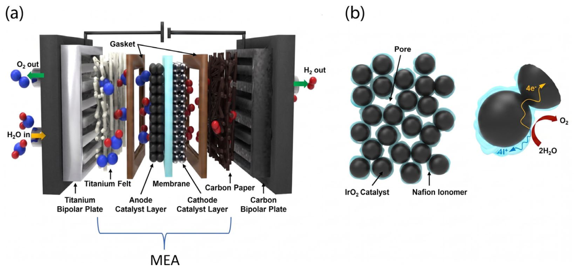
A typical PEMWE, as schematically illustrated in Figure 1, consists of a MEA sandwiched between two bipolar plates, forming the core electrochemical unit where water splitting and hydrogen production occur [25]. Unlike alkaline systems, PEMWEs employ a solid polymer electrolyte membrane that simultaneously serves as the ionic conductor and gas separator, enabling compact design and high current-density operation [26].
The MEA comprises a dense proton-conducting membrane, typically based on perfluorosulfonic acid polymers such as Nafion, positioned between two porous catalyst layers [28]. On the anode side, water is oxidized to generate oxygen, protons, and electrons, while on the cathode side, protons migrate through the membrane and are reduced to form high-purity hydrogen gas. The membrane selectively permits proton transport while preventing the crossover of product gases, thereby ensuring high Faradaic efficiency and safe operation.
Surrounding the catalyst layers are porous transport layers, usually made of titanium felt or sintered metal structures on the anode side and carbon-based materials on the cathode side [29]. These layers facilitate uniform distribution of reactant water, efficient removal of gaseous products, and enhanced electronic conductivity [30]. Bipolar plates, commonly fabricated from titanium or coated stainless steel, provide structural support and incorporate flow-field channels designed in serpentine or parallel patterns to optimize water supply and gas evacuation, thus mitigating mass transport limitations.
Embedded current collectors enable efficient electron transfer between the electrodes and the external circuit, minimizing ohmic losses and supporting high-performance hydrogen generation. In addition, PEMWE systems integrate power electronics and control units to regulate key operating parameters such as voltage, current density, temperature, and water flow rate, ensuring stable and safe operation under dynamic conditions [31].
A key advantage of PEMWEs lies in their modular stack architecture, where multiple single cells are connected in series to achieve the desired hydrogen production capacity. This modularity, combined with fast response, high efficiency, and the ability to operate under high pressure, makes PEMWE technology particularly attractive for renewable energy integration and large-scale green hydrogen production.
The electrochemical reactions occurring in PEMWE are expressed as follows [32]:
Anode reaction: H2O → 1/2O2 + 2H+ + 2e (E0 = +1.23 V vs. SHE)
Cathode reaction: 2H+ + 2e → H2 (E0 = 0.00 V vs. SHE)
Overall reaction: H2O → H2 + 1/2O2 (E0 = 1.23 V)
Through the coupled processes of oxygen evolution at the anode and hydrogen evolution at the cathode, PEMWEs enable efficient and reversible conversion of electrical energy into chemical energy stored in hydrogen.

2.2. Structure and Performance of Porous Transport Layers in PEMWE

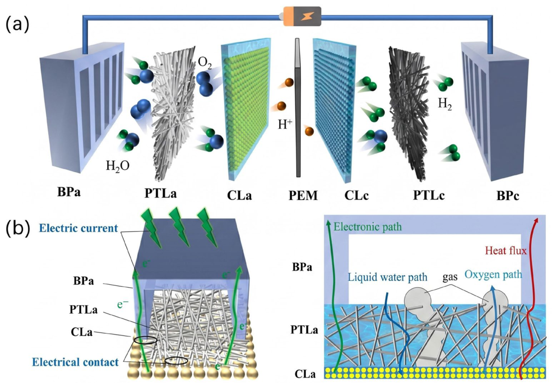
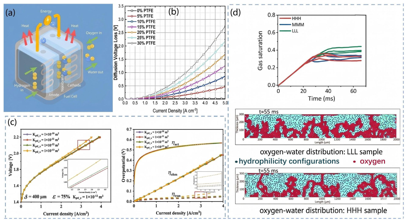
In PEMWEs, the porous transport layer (PTL) and catalyst layer (CL) constitute the core porous electrode region where electrochemical water splitting reactions occur. Similarly to porous electrodes in redox flow batteries, these porous media strongly affect reactant distribution, charge conduction, oxygen evacuation, and two-phase transport behavior. Therefore, accurate representation of PTL/CL microstructural parameters in multiphysics models is essential for predicting polarization losses and optimizing electrolyzer performance, particularly under high current density operation, as shown in Figure 2.
Among the structural parameters, PTL porosity plays a dominant role in governing effective diffusivity, permeability, and oxygen transport pathways. In PEMWE modeling, porosity is commonly incorporated through Bruggeman-type correlations:
D e f f = ε β D
where Deff is the effective diffusivity, ε is porosity, and β typically ranges from 1.5 to 2.0 [34,35]. The effective diffusivity directly affects the species transport behavior in the porous transport layer and is incorporated into the mass conservation equation.
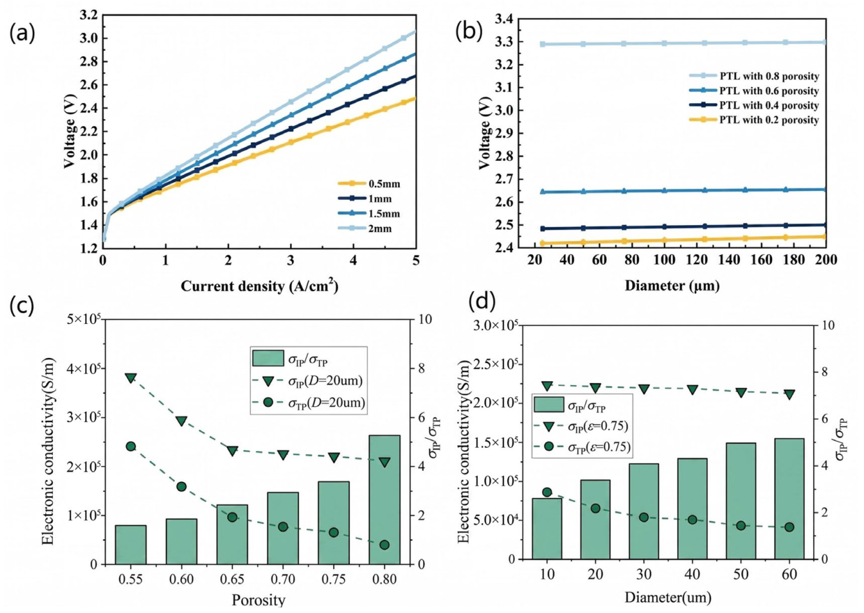
The structural parameters of the PTL exert a significant influence on the performance of PEMWE. As shown in Figure 3a, reducing the PTL thickness not only effectively lowers the ohmic overpotential but also shortens the gas diffusion pathways, thereby alleviating mass transport losses. Simulation results indicate that at a high current density of 5 A cm−2, decreasing the PTL thickness from 2 mm to 0.5 mm results in a substantial reduction in the cell voltage by approximately 0.576 V, which is mainly attributed to the pronounced decrease in ohmic overpotential. In addition, porosity and pore size are also critical factors in regulating performance. Lower porosity and smaller pore size are generally more favorable for improving efficiency. However, the influence of porosity on cell voltage is far more significant than that of pore size. As illustrated in Figure 3b, at 80 °C, reducing the porosity from 0.8 to 0.2 markedly decreases the operating voltage from 3.29 V to 2.424 V. In contrast, when the pore size is reduced from 200 μm to 50 μm, the voltage decreases by only 13.2 mV. Overall, employing a thinner PTL with lower porosity represents a key strategy for optimizing PEMWE performance. Furthermore, Figure 3c,d illustrate the effects of porosity and fiber diameter on the electronic conductivity and anisotropy of the PTL. When the fiber diameter is fixed at 20 μm, increasing the porosity from 0.55 to 0.80 leads to a significant decline in both in-plane and through-plane electronic conductivities due to the reduction in solid fiber content. During this process, the anisotropy ratio (defined as the ratio of in-plane to through-plane conductivity) increases markedly from 1.59 to 5.25. This indicates that at higher porosity, charge transport in the through-plane direction becomes more severely hindered. Regarding the effect of fiber diameter, as shown in Figure 3d, when the porosity is fixed at 0.75, increasing the fiber diameter from 10 μm to 60 μm results in a moderate increase in anisotropy; however, its influence is considerably weaker than that of porosity. This suggests that, compared with fiber diameter, porosity plays a more dominant role in regulating the electronic transport properties and directional conductivity distribution of the PTL.
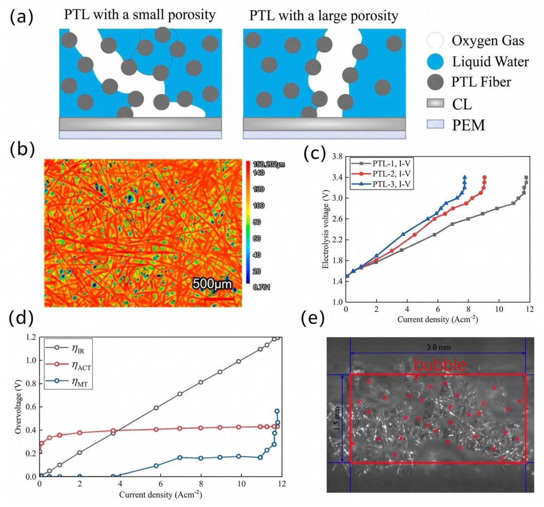
The coupled effects of PTL thickness and porosity exert a significant influence on PEMWE performance and the limiting current density. As shown in Figure 4a,b, when the PTL thickness is kept constant at 200 μm, lower porosity, such as 45%, leads to a microstructure lacking sufficient through-pores. This structural limitation forces oxygen bubbles to follow more tortuous and extended pathways before reaching the flow channel, effectively increasing the transport distance for both electrons and gas species while simultaneously raising ohmic resistance and mass transport overpotential. The experimental results in Figure 4c confirm that decreasing the porosity from 72% to 45% causes a pronounced reduction in the limiting current density, from 11.6 A per square centimeter to 7.9 A per square centimeter. Overpotential analysis in Figure 4d further shows that the ohmic overpotential increases approximately linearly with current density, whereas the mass transport overpotential rises sharply as the limiting current density is approached. This sudden increase is primarily due to membrane dehydration and the blockage of catalyst active sites by accumulated gas. Furthermore, visualization results in Figure 4e indicate that higher PTL porosity provides a greater density of bubble detachment sites, 7.5 per square millimeter for 72% porosity compared to 5.6 per square millimeter for 45% porosity. This facilitates rapid oxygen removal, reduces concentration polarization, and enhances permeability, thereby maintaining sufficient water supply to the catalyst layer at high current densities.
In addition to porosity and thickness, the permeability of the PTL plays a decisive role in governing liquid water infiltration and oxygen removal in PEMWEs. A higher permeability reduces two-phase flow resistance, thereby enhancing reactant supply and product evacuation. As shown in Figure 5c, Zhang et al. [38] employed a one-dimensional two-phase model and demonstrated that when the PTL permeability falls below approximately 1 × 10⁻¹² m2, gas diffusion is significantly hindered, resulting in a pronounced increase in mass-transport overpotential. In contrast, when the permeability exceeds this threshold, its impact on cell voltage becomes much less significant, indicating the existence of a critical permeability required to ensure efficient operation. Furthermore, recent experimental and modeling studies have reported that a PTL with a permeability of approximately 5 × 10⁻¹³ m2 exhibits lower gas saturation and improved water permeability compared with a structure of about 1 × 10⁻¹³ m2. This enhancement facilitates oxygen removal and helps maintain adequate hydration of the catalyst layer [39].
The wettability of the PTL likewise plays a pivotal role in two-phase transport. Hydrophilic pore surfaces facilitate water spreading within the pore network and promote bubble detachment, thereby mitigating oxygen accumulation and concentration polarization. Modeling analyses indicate that an untreated hydrophilic PTL exhibits nearly negligible diffusion overpotential even at current densities as high as 5.0 A cm−2. However, once hydrophobicity is introduced through PTFE treatment, the balance between water and gas transport is disrupted, leading to a substantial increase in diffusion losses. As illustrated in Figure 5b, when the PTFE loading increases from 0% to 5%, the diffusion voltage loss at 2.0 A cm−2 rises sharply from less than 10 mV to over 100 mV [40]. For a PTL treated with 20% PTFE, diffusion overpotential becomes evident as early as 0.7 A cm−2 and eventually dominates the overall cell voltage at high current densities. These findings highlight that the PTL must possess both high permeability and strong hydrophilicity to prevent gas accumulation within the pore structure, which would otherwise hinder mass transport and compromise CL hydration and reaction efficiency. As shown in Figure 5d, pore-scale simulations based on the LBM further elucidate the critical role of PTL hydrophilicity in regulating oxygen transport dynamics under high-current-density conditions [41]. Li et al. (2024) [41] demonstrated that at an extreme current density of 5 A cm−2, enhancing the overall hydrophilicity of the PTL significantly reduces oxygen saturation within the porous network. According to the dynamic evolution results in Figure 5d, the fully hydrophilic configuration (HHH sample, contact angle 30°) reaches a final average oxygen saturation of only 0.31, whereas the less hydrophilic LLL and LMH samples (contact angle 70°) exhibit much higher values of up to 0.41. This pronounced reduction in residual oxygen is primarily attributed to the stronger retreat behavior induced in highly hydrophilic regions after oxygen breakthrough. In the HHH sample, oxygen clusters contract more effectively back toward their original locations, thereby reopening previously occupied pore pathways and sustaining adequate water supply.
For traditional homogeneous PTLs, exhaustive simulations reveal that an optimal porosity of approximately 50% minimizes the total cell overpotential. Elevating porosity significantly beyond 50% critically diminishes the solid phase electron conduction pathways, precipitating a severe increase in ohmic resistance and compromising the mechanical support required to prevent membrane deformation under high differential pressures. Conversely, lowering porosity below 35% triggers catastrophic mass-transport limitations due to severe gas accumulation [38]. However, the most advanced industrial benchmark has shifted towards gradient porosity structures. By utilizing scalable tape-casting and roll-calendering manufacturing processes, next-generation PTLs achieve an ultra-high porosity backing layer (up to 75%) specifically engineered to maximize oxygen bubble transport and mitigate gas accumulation. This ultra-porous backing is seamlessly integrated with a much denser interfacial microporous layer (typically 25–50 μm thick) adjacent to the catalyst layer, which maximizes the electrochemically active Triple-Phase Boundary and ensures low interfacial contact resistance. Such gradient structures have demonstrated a definitive 127 mV reduction in cell voltage at 2.0 A cm−2 compared to homogeneous commercial PTLs [42].
The baseline thickness for optimally balancing in-plane electrical conductivity, mechanical robustness under elevated pressures, and efficient mass transport lies strictly between 250 μm and 400 μm [38]. While theoretical models occasionally suggest that ultra-thin PTLs (25–50 μm) drastically reduce bulk ohmic losses, empirical evidence shows these structures suffer from severe flow field land blockage and fail to prevent the membrane from extruding into the flow channels under operating pressures exceeding 30 bar [43]. Consequently, unless reinforced with specific sub-micron metallic interlayers (e.g., Tantalum), thicknesses below 200 μm are deemed suboptimal for unsupported industrial applications [44].

2.3. Structure and Performance of Catalyst Layers in PEMWE

While the PTL plays a crucial role in facilitating reactant supply and product removal, the electrochemical reactions themselves occur within the CL. Therefore, the structural characteristics and physicochemical properties of the CL are equally critical in determining the overall performance of PEMWE. The catalyst layer CL is a key functional component of the MEA in PEMWE, where the electrochemical reactions of water splitting occur. It is typically located between the proton exchange membrane and the PTL, serving as the interface for coupled electron, proton, and mass transport processes. The performance of PEMWE strongly depends on the microstructure and physicochemical properties of the CL.
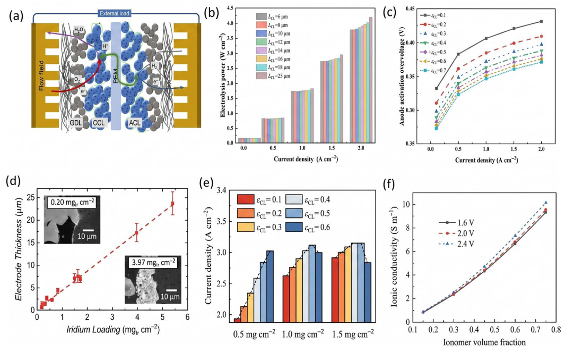
As shown in Figure 6a, the CL typically consists of catalyst nanoparticles, ionomer, and pore structures, forming a complex three-phase reaction interface. On the anode side, the CL generally employs noble metal catalysts such as Ir or IrO2 to promote the oxygen evolution reaction (OER) [45], while the cathode CL commonly uses Pt-based catalysts to catalyze the hydrogen evolution reaction (HER). These catalyst particles are mixed with proton-conducting ionomers and form agglomerated structures that provide electrochemically active sites as well as proton transport pathways, enabling the coupled transport of electrons, protons, and reactants [46].
Increasing catalyst loading generally enlarges the electrochemically active surface area and improves reaction kinetics by providing more accessible active sites. However, excessive catalyst loading leads to thicker CLs, which increases internal diffusion resistance and mass transport limitations, thereby offsetting the kinetic advantages [47]. As shown in Figure 6d, when the catalyst loading increases from 1 mg cm−2 to 2 mg cm−2, the electrode thickness correspondingly increases from 4 μm to 8 μm. This structural change further affects the electrolyzer performance. As illustrated in Figure 6b, with decreasing CL thickness, the electrolyzer voltage and power consumption initially decrease rapidly and then gradually stabilize. For example, at a current density of 1.5 A cm−2, reducing the CL thickness from 25 μm to 6–8 μm decreases the cell voltage from approximately 2.0 V to about 1.75 V, while the corresponding power consumption decreases from 2.95 W to 2.71 W. It should be noted that the optimization of CL thickness requires balancing the performance under different current density conditions. At a relatively low current density of 0.1 A cm−2, a moderately thicker CL of about 8 μm may exhibit a lower overpotential than a thinner CL of about 6 μm. This indicates that an optimal CL thickness window exists in proton exchange membrane water electrolysis PEMWE, which is crucial for achieving a balance between high current density operation and low energy consumption.
Figure 6. Catalyst layer structure and its influencing factors on performance. (a) Schematic diagram of the catalyst layer structure in water electrolysis. Reprinted with permission from Ref. [46], 2025, Springer; (b) Effect of catalyst layer thickness; (c) Effect of catalyst layer porosity. Reprinted with permission from Ref. [48], 2024, Elsevier; (d) Effect of catalyst loading on electrode thickness. Reprinted with permission from Ref. [49], 2018, IOPSCIENCE; (e) Influence of catalyst loading and porosity on electrolyzer performance; (f) effective ionic conductivity at different ionomer volume fractions; Reprinted with permission from Ref. [50], 2024, Elsevier.
Energies 19 02361 g006
The porosity and pore structure of the catalyst layer also play an important role in the transport of reactant water and the removal of generated oxygen. As shown in Figure 6c, the variations in anodic activation overpotential and ohmic overpotential at different CL porosities are presented. Increasing porosity not only reduces the anodic activation overpotential by optimizing the three phase reaction interface, with a reduction of about 0.06 V at 1.5 A cm−2, but also has a more pronounced influence on the ohmic overpotential. This difference indicates that regulating CL porosity to reduce ohmic losses is an important strategy for improving the energy efficiency of membrane electrode assembly MEA at high current densities.
In addition, Figure 6e shows that a strong physical coupling exists between CL thickness and porosity. Although increasing porosity is beneficial for improving mass transport, it also significantly increases the CL thickness, particularly under high catalyst loading, and results in an approximately linear decrease in the active specific surface area. The influence of this structural evolution on performance exhibits a clear voltage dependence. In the kinetically controlled region at low voltage, the current density increases exponentially with increasing porosity, whereas in the high-voltage region around 2.4 V, the increase becomes nearly linear. Moreover, this enhancement effect becomes more significant at a higher catalyst loading of 1.5 mg cm−2.
In addition to catalyst loading and porosity, agglomeration is another important factor influencing the microstructure of PEMWE catalyst layers. In PEMWE simulations, the agglomerate model is commonly used to describe the catalyst layer structure, where catalyst nanoparticles tend to form clusters with characteristic sizes typically on the order of hundreds of nanometers. Smaller agglomerates can improve catalyst utilization and shorten the diffusion pathways of reactants, thereby enhancing the overall electrolysis performance. In contrast, larger agglomerates can lead to more significant diffusion limitations within the catalyst structure and reduce the accessibility of active sites.
As shown in Figure 6f, when the ionomer volume fraction increases from 0.15 to 0.75, the effective ionic conductivity under operating voltages ranging from 1.6 V to 2.4 V increases from 8.47 S m−1 to 9.29 S m−1. This stepwise increase in ionic conductivity effectively reduces the ohmic losses caused by limited proton transport within the agglomerate structure. As a result, in the kinetically controlled region at low voltage, the current density shows an exponential increase with increasing ionomer content.
In summary, the microstructure of the CL serves as a critical link connecting the electrochemical reaction kinetics and mass transport characteristics in proton exchange membrane water electrolysis PEMWE systems. To meet the operational demands of industrial-scale high current densities, rational design of the CL is essential. This involves not only optimizing the catalyst loading and its spatial distribution but also precisely regulating the ionomer content and pore architecture, including pore size distribution and connectivity. Such coordinated design enables a balance between reducing activation overpotential and enhancing gas–liquid mass transport, thereby ensuring high efficiency and long-term operational stability of the electrolyzer.
In terms of catalyst loading, the iridium (Ir) loading in current commercial PEMWE anodes remains excessively high (approximately 2.0–3.0 mg/cm2), resulting in prohibitively high costs. The U.S. Department of Energy has explicitly set a 2026 commercialization target to reduce the total platinum group metal loading to 0.125 mg_Ir/cm2 or lower [43]. In recent years, by employing atomically dispersed strategies or anchoring Ir nanoparticles onto acid-resistant metal oxide supports (e.g., Ir–MnO2 or IrOx/KTO), studies have successfully achieved outstanding performance of 3.0 A cm−2 at 1.8 V under ultra-low loadings of 0.05–0.1 mg_Ir cm−2. This establishes a quantitative benchmark for future catalyst design [51].

2.4. Electrode Reaction Kinetics

In PEMWEs, the electrochemical reactions occurring at the catalyst layers are typically described using Butler–Volmer kinetics, which relates the electrochemical reaction rate to the activation overpotential at the electrode–electrolyte interface. In PEMWE systems, water oxidation takes place at the anode catalyst layer, while hydrogen evolution occurs at the cathode catalyst layer. These reactions occur within porous catalyst layers coupled with proton transport through the membrane and the transport of liquid water and gaseous oxygen in the PTL [2,52].
The volumetric exchange current densities at the anode and cathode are expressed as [2,53]:
j a = a i 0 , a [ exp ( α a F η a R T ) exp ( α a F η a R T ) ]
j c = a i 0 , c [ exp ( α a F η c R T ) exp ( α c F η c R T ) ]
where a is the specific surface area of the catalyst layer, i0 is the area-specific reference exchange current density, αa is the charge transfer coefficient at the anode and cathode, and η is the activation overpotential.
The activation overpotential η at the catalyst layer is defined as [54]:
η = ϕ s ϕ m E e q
E e q = 1.229 9 × 10 4 ( T 298.15 )
where ϕs is the solid phase potential; ϕm is the electrolyte phase potential; Eeq is the equilibrium potential of the electrode reaction.
The electrochemical kinetics in PEMWEs are strongly influenced by gas evolution phenomena. Bubbles generated at the catalyst layer can partially block active sites and increase local mass transport resistance [55,56]. The presence of bubbles reduces the effective electrochemically active area and increases activation losses. Therefore, many PEMWE models modify the Butler–Volmer equation by introducing a bubble coverage factor (1 − θb) to represent the reduction in the effective active surface area [57].
j a = a i 0 , a ( 1 θ b ) [ exp ( α a F η a R T ) exp ( α a F η a R T ) ]
j c = a i 0 , c ( 1 θ b ) [ exp ( α a F η c R T ) exp ( α c F η c R T ) ]
The bubble coverage θb is related to factors such as current density, temperature, flow velocity, bubble diameter, and diffusion coefficient:
θ b = 3 16 R e S c F o f G
where Re is the Reynolds number, Sc is the Schmidt number, Fo is the Fourier number, and fG is the gas evolution efficiency.

2.5. Mass Transport and Species Processes

Mass transport within the PTL and CL plays a crucial role in determining the performance of PEMWEs. During operation, liquid water must be continuously supplied to the anode catalyst layer while the generated oxygen bubbles must be efficiently removed from the porous structure. Insufficient water supply or oxygen accumulation can lead to severe mass transport limitations, resulting in concentration overpotential and reduced electrolysis efficiency. At high current densities, the formation and accumulation of oxygen bubbles within the CL and PTL can block active catalytic sites and hinder reactant transport, thereby significantly affecting the local reaction kinetics and overall cell performance. Therefore, understanding and accurately modeling the mass transport behavior in porous electrodes is essential for optimizing PEMWE design and operation [43].
In numerical modeling, the transport of species within porous electrodes is typically described by the mass conservation equation. For a given species i, the species conservation equation can be expressed in the following general form [58,59]:
t ( ε c i ) + N i = R i = s i a v i l o c n F
where ci denotes the concentration of species i, ε is the electrode porosity, t is time, N i represents the flux of species i, and Ri is the source term accounting for the production or consumption of species due to electrochemical reactions. This equation describes the temporal and spatial evolution of reactant and product concentrations within the porous electrode and serves as the foundation for analyzing mass transport phenomena in PEMWE systems.
To more accurately describe the transport behavior of charged species, such as protons, within the electrolyte phase, the extended Nernst–Planck equation is commonly employed. This equation accounts for three primary transport mechanisms: diffusion driven by concentration gradients, migration induced by electric potential gradients, and convection resulting from fluid flow. The species flux can be expressed as [59]:
N i = D i e f f c i z i c i D i e f f F R T ϕ l + v c i
where D i e f f is the effective diffusion coefficient, which incorporates the influence of electrode porosity and tortuosity on the diffusion pathway; zi is the ionic charge, F is the Faraday constant, R is the universal gas constant, T is the absolute temperature, ϕl is the liquid-phase potential, and v is the convective velocity of the electrolyte. This formulation provides a comprehensive description of ionic transport in porous electrodes by incorporating diffusion, electromigration, and convective effects.
In addition to ionic transport, the flow of liquid water through the porous transport layer is commonly described using Darcy’s law [60,61]:
v l = K μ l p l
where vl represents the liquid velocity, K is the permeability of the porous medium, μl is the dynamic viscosity of the liquid phase, and pl is the liquid pressure. The permeability is closely related to the microstructure of the PTL and can be estimated using the Kozeny–Carman equation [62]:
K = ε 3 d f 2 16 C ( 1 ε ) 2
where df denotes the fiber diameter of the porous medium. ε represents the porosity, and C is the Kozeny constant. This relationship links the microscopic structural properties of the PTL with its macroscopic flow characteristics and is widely used in porous electrode modeling. The velocity vl calculated from Darcy’s law provides the physical input for the convective term in Nernst–Planck equation, thereby enabling the full coupling between water transport and species transport.
The cathodic HER is neglected in this study due to its significantly higher exchange current density and lower mass transport resistance compared to the anodic OER, which is generally regarded as the rate-determining step and the primary source of voltage loss [63,64]. Under high current density operation, the OER at the anode produces a large amount of oxygen gas, leading to the formation of gas bubbles within both the CL and PTL [65]. The nucleation, growth, and detachment of these oxygen bubbles induce complex gas–liquid two-phase flow within the porous structure [66,67].
These bubbles can significantly affect mass transport processes in multiple ways. Specifically, they may occupy pore space, thereby reducing the effective permeability for liquid water transport, and can also block catalytic active sites, leading to a decrease in the effective electrochemically active surface area [68,69]. Consequently, gas–liquid two-phase transport becomes a critical factor limiting the performance of PEMWEs under high-current-density conditions [70,71].
In two-phase flow modeling of porous electrodes, the conservation of the gas phase is typically described using a volume-averaged mass conservation equation. The governing equation can be written as [18]:
( ε ρ g α g ) t + ( ρ g v g ) = S g
where αg represents the gas volume fraction, vg is the gas velocity, and Sg is the gas generation source term. The rate of oxygen generation is typically determined by Faraday’s law, which relates the electrochemical reaction rate to the current density [59,72]:
S O 2 = a v i l o c 4 F M O 2
where i is the current density and F is the Faraday constant. and MO2 is the molar mass of oxygen.
Under two-phase flow conditions, the transport of the liquid and gas phases within porous media is often described using the two-phase Darcy equations [60,73]:
v i = K k r i μ i p i
where K is the intrinsic permeability of the porous medium, kri is the relative permeability of phase i, μi is the dynamic viscosity, and pi is the phase pressure.
Furthermore, the pressure difference between the gas and liquid phases is coupled through the capillary pressure relationship, which depends on the pore size distribution and wettability of the PTL [74]:
p c = p g p l
where pc is the capillary pressure, which depends on the pore structure and wettability of the porous medium. Capillary pressure plays a key role in determining the nucleation, retention, and removal of gas bubbles within the porous transport layer.
Gas bubble accumulation reduces the effective transport properties of porous electrodes, which is commonly accounted for by introducing a gas saturation-dependent correction to the effective diffusivity [75]:
D i e f f = D i ε 1.5 ( 1 s l q ) 1.5
where slq is the liquid water volume fraction. Within the CLs, the transport of both protons and electrons is governed by the conservation of charge, following Ohm’s law [72]:
( σ l e f f ϕ l ) + a v i l o c = 0
( σ s e f f ϕ s ) a v i l o c = 0
where av is the effective specific surface area, iloc is the local current density, and the term aviloc represents the volumetric current source; σ denotes the effective conductivity, while ϕs and ϕl represent the solid-phase and liquid-phase potentials, respectively.
The liquid water consumption and oxygen bubble generation induced by the OER at the anode side, along with their competitive gas–liquid two-phase transport mechanism in the PTL, and the electro-osmotic drag and back-diffusion behaviors accompanying proton conduction within the PEMWEs, collectively constitute the core mass transport processes in PEMWEs.
In the anode CL, the OER is expressed as: 2H2O → O2 + 4H+ + 4e. This reaction not only has sluggish kinetics but also directly consumes liquid water molecules. As the current density increases, the local water consumption rate increases sharply; if it cannot be replenished by the PTL in a timely manner, “dry zones” will form near the active sites of the catalyst, significantly increasing activation and concentration overpotentials. Simultaneously, the generated oxygen nucleates in the form of tiny bubbles within the nanoscale pores. The three-dimensional dual-scale pore network model (PNM) by Yang Xu et al. (2025) [76] indicates that after these bubbles are generated in the CL, they migrate and become trapped in the PTL, thereby blocking the return channels for water and creating a coupled limitation in gas–liquid transport.
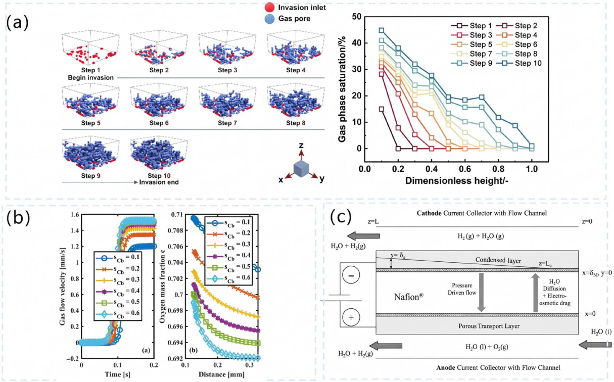
The specific manifestation of this gas–liquid competitive process in the PTL can be revealed through gas invasion behavior and its saturation evolution. As shown in Figure 7a, after the gas enters the PTL from the CL, it preferentially invades the bottom pores and gradually expands upwards. This process is not a simple unidirectional advance; rather, lateral expansion occurs within the same horizontal layer, causing the gas phase to accumulate in local regions and increase in saturation. For example, when the gas phase initially invades, the gas saturation in the first layer of the PTL is approximately 15%; as the invasion progresses to the second layer, this value can rise to about 30%. Overall, the gas phase saturation exhibits a decreasing trend along the thickness direction. This is primarily due to the existence of preferential invasion pathways, causing gases generated at different locations to gradually converge into larger gas clusters.
Building upon this, the impact of insufficient water supply to the anode on mass transfer behavior is further exacerbated. As shown in Figure 7b, when the liquid water supply is restricted, the local current density drops, leading to a reduced oxygen generation rate and a simultaneously weakened gas removal capability, which in turn causes the accumulation of oxygen at the anode side. This coupled “low generation–low removal” effect deteriorates mass transfer conditions, ultimately leading to mass transport limitations and performance degradation.
On the membrane side, the conduction of H+ from the anode to the cathode is accompanied by significant water transport behavior. Electro-osmotic drag causes water molecules to migrate with protons from the anode to the cathode, while back-diffusion, driven by the concentration gradient, prompts water to flow back from the cathode to the anode. These two transport processes operating in opposite directions jointly determine the water content distribution within the membrane. To quantitatively describe this competitive mechanism, as shown in Figure 7c, Shikhar Motupally et al. (2024) [78] developed a one-dimensional transport model that integrated diffusion, electro-osmotic drag, and pressure-driven flow into a unified analytical framework, successfully predicting the water content distribution within the membrane under various operating conditions.

2.6. Flow Field Comparison at High Current Density and Pressure

The geometric architecture of the bipolar plate flow field dictates the overarching hydrodynamics of the gas–liquid two-phase flow. The selection of flow field topology profoundly impacts PEMWE performance, particularly under the demanding regimes of high current densities (>2.0 A cm−2) and high differential pressures (e.g., 30–70 bar). The comparative advantages and detriments of leading flow field configurations are synthesized below and detailed in Table 1.
Parallel flow fields consist of straight, independent channels, parallel configurations inherently feature the lowest pressure drop among traditional designs, minimizing parasitic pumping power. However, they suffer from highly uneven fluid distribution and severe flow maldistribution. At elevated current densities, massive volumes of evolved oxygen gas rapidly coalesce into large slugs within the straight channels. Because adjacent channels experience nearly identical pressure profiles, there is no lateral driving force to dislodge these slugs, leading to profound reactant starvation, severe concentration polarization, and detrimental thermal hotspots [51]. Therefore, parallel designs are entirely suboptimal for high-current-density operations.
Serpentine and Interdigitated Flow Fields are designed to combat mass transport limitations by purposefully generating significant pressure differentials between adjacent channels. This spatial pressure gradient drives fluid laterally through the underlying porous transport layer, a phenomenon known as under-rib convection. This forced convective mechanism is highly efficient at violently purging trapped oxygen bubbles from the PTL matrix and replenishing active sites with liquid water. Consequently, these configurations significantly outperform parallel designs at high current densities, demonstrating superior Faradaic efficiency [79]. However, this electrochemical enhancement is achieved at the severe cost of exceptionally high pressure drops, which escalate system energy consumption. Furthermore, the rigid rib-channel geometry induces highly non-uniform in-plane mechanical stresses, which can accelerate the structural deformation and degradation of the Catalyst Coated Membrane under high-pressure environments (e.g., 10 bar) [13].
Advanced topologies including annular, biomimetic, and 3D mesh are developed to resolve the paradox between high mass transport, which requires high pressure drop, and system efficiency. Recent CFD-guided optimizations have yielded advanced 3D structures. Annular flow fields, modeled upon Murray’s branching law (mimicking biological vascular networks), promote exceptionally uniform velocity and thermal distributions. Empirical validations confirm that annular designs achieve a 29.9% higher current density output compared to parallel fields at 2.6 V whilst remarkably reducing the overarching pressure drop by 46.1% relative to serpentine designs [80]. Similarly, 3D Mesh fundamentally eliminate the solid rib structure, substituting it with a gradient pore matrix. This architecture provides exceptionally uniform mechanical stress distribution across the delicate MEA, increases interfacial water saturation by 110%, and reduces cell voltage by approximately 50 mV at 2.0 A cm−2 [81]. For next-generation industrial electrolyzers tasked with operating at extreme current densities and pressures, biomimetic and 3D mesh topologies clearly represent the optimal structural choice.
To summarize the complex multiphysics nature across different PEMWE components discussed in this section, the key reaction characteristics and their corresponding modeling features are synthesized in Table 2. This component-level mapping serves as a foundational reference for the various multi-dimensional modeling approaches detailed in the following section.

3. Multi-Dimensional Modeling Frameworks for PEMWEs

Modeling studies of PEMWE span a wide range of spatial and temporal scales, from microscopic electrocatalytic interfaces to macroscopic system-level behavior. Different modeling frameworks offer distinct trade-offs between computational efficiency and predictive accuracy, thereby supporting a broad spectrum of objectives ranging from fundamental mechanistic understanding to system-level optimization and industrial application [88,89,90].
At the macroscopic level, continuum models remain the most widely adopted approach for simulating the internal states and coupled electrochemical processes within electrolyzers. These models are generally formulated through nonlinear partial differential equations describing mass, momentum, charge, and energy conservation, enabling quantitative analysis of transport phenomena and reaction kinetics in PEMWE systems [2,91]. In addition, alternative modeling strategies have been developed, including zero-dimensional lumped-parameter models [92], pore-scale representations, and multiscale coupling frameworks [93,94], each providing complementary perspectives on system behavior and improving either physical interpretability or computational efficiency.
However, a critical analysis of the existing literature reveals that long-standing reliance on physics-driven continuum models introduces significant homogenization errors. In particular, macroscale continuum formulations typically assume spatially uniform porosity and permeability within the PTL. This volume-averaging assumption fails to capture key localized phenomena such as dry-out, capillary fingering, and non-uniform gas accumulation, which become dominant under high-current-density operation [95]. Furthermore, continuum equations are unable to resolve the strongly anisotropic nature of multiphase transport in realistic PTL geometries, leading to a systematic underestimation of mass transport overpotentials [96].
Although multiscale modeling frameworks attempt to bridge molecular-scale descriptions (e.g., density functional theory) with continuum-scale equations, they remain fundamentally constrained by scale-separation assumptions. The coupling of processes across widely disparate spatial and temporal scales inevitably induces error propagation, while many transferred parameters rely on simplified parameterizations that are often difficult to validate using available macroscopic experimental diagnostics.
Recognizing these intrinsic physical and computational limitations, recent developments indicate a clear shift in PEMWE modeling toward hybrid paradigms. In particular, the integration of Physics-Informed Neural Networks (PINNs) with multiscale modeling strategies has emerged as a promising direction. By embedding governing physical laws such as the Nernst–Planck and Tafel relations directly into the loss functions of deep learning architectures, these hybrid frameworks enforce physical consistency while preventing non-physical predictions. At the same time, they substantially reduce the computational burden associated with high-fidelity numerical simulations (e.g., Lattice Boltzmann methods) and address the limited generalization capability and “black-box” nature of purely data-driven approaches [97].

3.1. Lumped Parameter Models

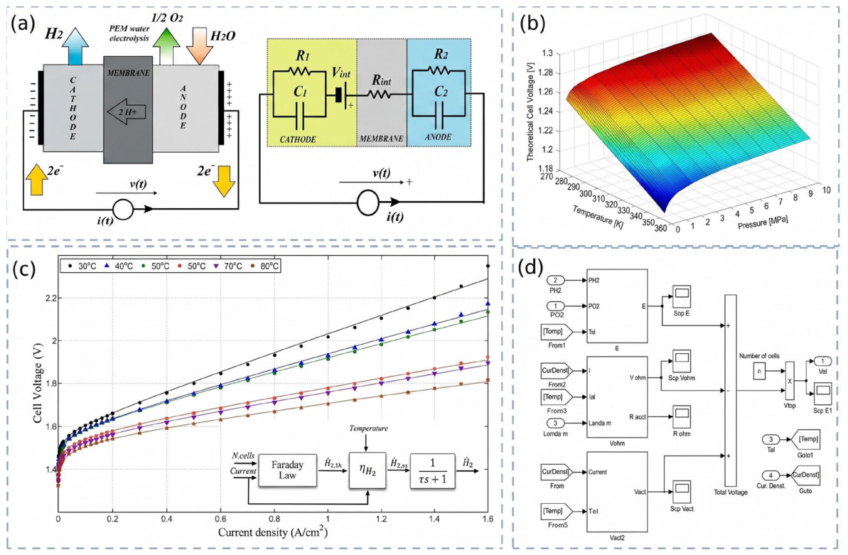
In PEMWE modeling, zero-dimensional lumped-parameter models significantly improve computational efficiency by simplifying the complex electrochemical system into a set of controlled algebraic equations or ordinary differential equations. The core concept of this approach is the introduction of an equivalent circuit model, which maps the physicochemical processes within the electrolyzer to combinations of electrical components. As illustrated in Figure 8a, under the dynamic operating conditions induced by intermittent renewable energy sources, conventional steady-state models struggle to capture the transient response of the electrolyzer under rapidly fluctuating currents. To address this limitation, Guilbert, Vitale, and co-workers developed the classical exponential model to accurately describe capacitive effects under dynamic current profiles [92]. This model characterizes the voltage response through a nonlinear coupling of ohmic resistance, activation overpotential, and diffusion overpotential, with its key innovation being the incorporation of double-layer capacitance effects. Their results demonstrate that, when the current changes, charge accumulation and release at the electrode–electrolyte interface lead to an exponential rise or decay in voltage, rather than an instantaneous transition to steady state. By mathematically describing the time evolution of these electrical components, the model is capable of reproducing the transient voltage behavior of both three-electrode systems and industrial-scale electrolyzer stacks with high accuracy.
In addition to the exponential model proposed by Guilbert and Vitale, various types of lumped-parameter models have been validated through specific graphical data, demonstrating their applicability in PEMWE and their capability to address targeted problems. As shown in Figure 8b, F. Marangio et al. (2009) developed and validated a zero-dimensional lumped-parameter model based on voltage decomposition [98]. This model enables highly accurate predictions of the polarization characteristics of high-pressure PEMWEs and demonstrates broad applicability and robust parameter analysis under various operating conditions, as confirmed by experimental data. Furthermore, R. García-Valverde et al. (2019) proposed a semi-empirical lumped-parameter model based on voltage decomposition for rapid prediction of steady-state polarization performance [99]. As shown in Figure 8c, the simulated curves from the proposed model are compared with experimental data from two PEMWEs. The results indicate that the model provides a good fit to the experimental data from both electrolyzers. Additionally, as shown in Figure 8d, T. Yigit and O. F. Selamet (2019) [100] proposed a thermo-electro-hydrogen lumped-parameter model based on simulations for system-level dynamic analysis. This model can simultaneously capture the dynamics of fast variables (voltage) and slow variables (temperature), making it suitable for dynamic simulations and control optimization under renewable energy-coupled operation.
In summary, lumped-parameter models with different structures can effectively address key issues in PEMWE systems, including steady-state performance prediction, transient response characterization, and system-level dynamic optimization, while maintaining high computational efficiency. Although these models cannot resolve detailed spatial distributions within the electrolyzer, they remain highly valuable for balancing computational cost and predictive capability. When a deeper understanding of internal physicochemical mechanisms is required, more detailed continuum or multiscale modeling approaches become necessary. However, due to inherent spatial averaging assumptions, even continuum-based models may not fully capture localized multiphase transport phenomena and structural heterogeneities. This limitation has motivated the development of microscale modeling approaches, which aim to resolve interfacial processes and pore-scale transport behavior with higher fidelity.

3.2. Microscale Modeling

To overcome the intrinsic limitations of continuum assumptions in resolving local interfacial phenomena, microscale modeling approaches have been developed. Microscale modeling of PEMWE focuses on the fundamental physicochemical processes occurring within the CL, membrane, and PTL, with particular emphasis on transport and reaction phenomena at the solid–liquid–gas three-phase interface. At this scale, models typically involve the coupling of mass transport (e.g., water and oxygen diffusion), charge transport (proton and electron conduction), electrochemical reaction kinetics, and interfacial phenomena such as gas evolution [101,102].
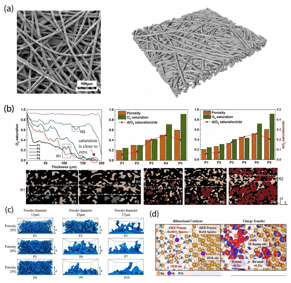
At the pore scale, the lattice Boltzmann method (LBM) has emerged as a powerful and widely adopted tool for investigating two-phase flow dynamics in PEMWE systems. Recent studies have demonstrated that the microstructure of the PTL plays a decisive role in oxygen bubble nucleation, growth, and detachment. For instance, as shown in Figure 9c, Changwook Kim et al. employed LBM to simulate oxygen bubble dynamics in both powder-type and fiber-type PTLs, quantitatively revealing how variations in porosity and pore size influence device-level performance and confirming that microstructural optimization can significantly reduce mass transport resistance [103]. Similarly, as illustrated in Figure 9b, Chenyang Xu et al. constructed a multiphase LBM model based on three-dimensional pore structures of commercial sintered titanium PTLs obtained via micro-computed tomography. Their results systematically showed that porosity, pore size distribution, and wettability strongly affect oxygen saturation and effective diffusivity, thereby quantitatively elucidating the mechanisms governing mass transport limitations [102]. These findings not only validate earlier qualitative understandings of gas blockage effects but also provide quantitative design guidelines. This conclusion is further reinforced by Rui Lin et al. (2024) [103] who, as shown in Figure 9a, reconstructed realistic three-dimensional PTL structures using X-ray tomography and coupled them with LBM simulations. Their results demonstrate that tailoring hierarchical porosity and wettability can effectively guide directional oxygen transport, thereby enhancing electrolyzer performance [104].
In addition, image-based reconstruction and PNM approaches have been extensively developed. The group of Pablo A. García-Salaberri (2025) [101] combined macroscale rib/channel models with microscale interfacial analyses at the PTL/CL interface, highlighting the importance of the contact line length as a key integrated descriptor of electrochemical activity, which directly stems from realistic interfacial morphology [101]. Meanwhile, Yang Xu et al. (2024) [76] developed a three-dimensional dual-scale PNM capable of resolving mass transport in both the anode PTL and CL. Their results clearly indicate that microporous structures within the CL are essential for maintaining liquid water supply at high current densities, whereas the macroporous structure of the PTL primarily governs oxygen removal. Furthermore, Mitchell Sepe et al. (2024) generated bilayer PTL structures using advanced imaging techniques and applied multiscale modeling to successfully correlate microstructural features with macroscopic cell performance, providing a solid theoretical foundation for the design of gradient PTLs [106].
At the molecular scale, density functional theory (DFT) calculations continue to provide atomistic insights into the OER mechanism and guide the design of advanced catalysts. Recent studies have shifted toward developing low-iridium or non-iridium catalysts to reduce cost. For example, Ziqiang Niu et al. (2025) [105] reported a single-atom Sb-doped RuSbOx bifunctional catalyst. As shown in Figure 8d, DFT calculations reveal that Sb doping tunes the d-band center of Ru, thereby maintaining high OER activity while significantly enhancing stability in acidic environments, enabling stable PEMWE operation for over 1000 h at 2.0 V [105]. Another notable study by Ke Sun et al. [107] introduced deformable hollow IrOx nanospheres, which reduce iridium loading by approximately 80% while improving electron/mass transport and structural stability. In addition, Zhou, H. et al. (2025) [108] synthesized Ni@IrO2 core–shell catalysts via a facile substitution method; DFT analysis showed that strong electronic interactions between the Ni core and IrO2 shell effectively modulate oxygen adsorption energy at Ir sites, thereby enhancing intrinsic OER activity while significantly reducing noble metal usage [107].
In summary, recent advances that integrate pore-scale simulations such as LBM and FEM with molecular-scale calculations such as DFT have systematically revealed the performance-limiting mechanisms in PEMWE across multiple dimensions, including two-phase transport, local reactant distribution, and interfacial reaction energetics. These studies not only quantitatively confirm key phenomena, such as the fact that increased oxygen saturation leads to mass transport limitations, that high-porosity regions enhance gas removal, and that OER energy barriers play a critical role in determining catalytic activity, but also provide direct and robust theoretical guidance for optimizing catalyst layer microstructures, designing gradient or multilayer PTLs, and developing highly active catalysts with reduced noble metal content. Collectively, these efforts significantly promote the advancement of PEMWE technology toward higher efficiency, lower cost, and large-scale deployment.

3.3. Multi-Scale Modeling

The multiscale coupling framework, as a key approach for bridging physical processes across different scales, is fundamentally based on constructing appropriate models at the micro-, meso-, and macro-scales to capture the dominant physicochemical phenomena at each level. Through strategies such as parameter transfer, boundary condition coupling, and nested solution schemes, cross-scale information integration can be effectively achieved, thereby establishing a systematic understanding that links underlying mechanisms to overall performance [109,110]. Within this framework, the electrochemical reaction kinetics in the catalyst layer, pore-scale multiphase transport behavior, and the overall electrolyzer performance can be coherently integrated, enabling intrinsic correlations among processes at different scales. This provides a solid theoretical foundation for advancing PEMWE from material design to system-level optimization. Recent studies have further validated the effectiveness of this framework and continuously expanded its applicability and analytical depth in addressing complex multiphysics coupling problems [91,111].
At the microscale, research focuses on the quantum mechanical origins of intrinsic catalytic activity. For example, density functional theory calculations can reveal the adsorption energies of oxygen-containing intermediates such as *O and *OH on catalyst surfaces, which fundamentally determine the overpotential of the OER. Recent studies have shown that tuning the electronic spin configuration can significantly enhance catalytic activity, thereby providing theoretical guidance for the design of highly efficient catalysts [112]. In addition, for non-noble metal catalysts such as manganese oxides, optimizing the lattice oxygen structure, for instance by replacing pyramidal oxygen with planar oxygen to form stronger Mn–O bonds, enables stable operation at high current densities up to 1000 mA cm−2 for more than one month. This improvement directly arises from precise control of the atomic-scale bonding environment [113].
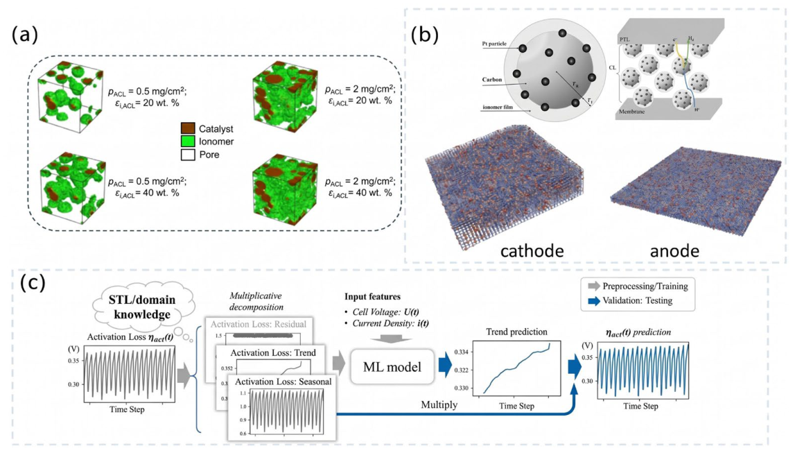
At the mesoscale, attention is directed toward the complex porous structure of the catalyst layer and its influence on transport and reaction processes. The catalyst layer is not homogeneous but consists of a three-dimensional network formed by catalyst particles, ionomer, and pores. At this scale, as illustrated in Figure 10a, PNMs are employed to describe the transport pathways of water, oxygen, and protons with high fidelity. Studies have demonstrated that microstructural properties of the catalyst layer, including porosity, tortuosity, and connectivity, significantly affect cell voltage, activation overpotential, and ohmic losses [48]. Navneet Goswami and co-workers developed a detailed microstructural model of the catalyst layer to investigate its mechanistic impact on PEMWEs performance, highlighting the importance of maintaining high hydrogen flux while reducing the loading of expensive catalysts [114]. Another study, as shown in Figure 10b, coupled the pore network representation of the catalyst layer with a macroscale performance model to establish a multiscale framework, successfully capturing the coupled effects of mass transport, heat transfer, and electrochemical reactions across the entire electrolyzer [93]. Such mesoscale modeling is essential for understanding the dynamic evolution of the three-phase interface involving gas, liquid, and solid catalyst, which constitutes the core region of electrochemical reactions.
At the macroscale, the focus shifts to the overall performance, efficiency, and durability of the electrolyzer or stack. Models at this level are typically based on continuum assumptions and involve solving conservation equations for mass, momentum, energy, and charge. A key aspect of multiscale coupling lies in effectively transferring information obtained from the micro and mesoscales into parameters for macroscale models. For example, elementary reaction rate constants derived from density functional theory calculations can be used to construct microkinetic models, which subsequently yield the exchange current density in the Butler–Volmer equation. Similarly, effective diffusivity and conductivity obtained from pore network simulations can be directly incorporated as transport properties in continuum models. This bottom-up parameter transfer strategy ensures that macroscale models are grounded in physical principles rather than purely empirical fitting.
Recent advances have not only validated the effectiveness of this framework but also significantly expanded its scope. On the one hand, machine learning techniques are increasingly introduced to accelerate multiscale modeling. As illustrated in Figure 10c, Xia Chen and co-workers proposed a knowledge-integrated machine learning framework that systematically combines data-driven models with domain-specific physical insights to address key challenges in PEMWE development [115]. On the other hand, growing attention has been paid to multiscale coupling under dynamic operating conditions. Dayron Chang Dominguez and co-workers applied a time multiscale approach to efficiently simulate degradation processes in PEMWEs under transient conditions, which is essential for understanding system durability under fluctuating renewable energy input [81]. Furthermore, purely mechanical factors such as stress have been demonstrated to exert a decisive influence on overall efficiency and stability, which requires the integration of mechanical fields into multiscale models [116]. At the material level, an improved understanding of the role of ionomers within the catalyst layer has further enriched multiscale modeling. Ionomers not only facilitate proton transport but also influence electronic insulation and water uptake, and their properties such as long or short side chain perfluorosulfonic acid directly affect the microenvironment within the catalyst layer [117].
In summary, the multiscale coupling framework has evolved from an initial conceptual methodology into a comprehensive research platform integrating quantum chemical calculations, pore-scale simulations, continuum modeling, machine learning, and mechanical analysis. This framework provides a powerful tool for elucidating complex physicochemical processes in PEMWEs systems at the microscopic level and offers systematic theoretical guidance and optimization pathways for scaling from laboratory research to large-scale industrial applications. With continuous advances in computational capabilities and deeper interdisciplinary integration, multiscale coupling is expected to play an increasingly critical and indispensable role in advancing green hydrogen technologies.
Nevertheless, despite these significant advances, several inherent limitations remain. In particular, traditional multiscale frameworks often rely on scale-separation assumptions, and the coupling of processes across disparate spatial and temporal scales may lead to error propagation and increased computational complexity. In this context, hybrid modeling approaches have recently emerged as a promising direction. Among them, PINNs have attracted growing attention. By embedding governing equations directly into neural network architectures, these methods provide a potential pathway to bridge physics-based and data-driven modeling while reducing computational cost and improving generalization capability.

3.4. Model Validation Rigor and Quantitative Prediction Errors

A paramount challenge in assessing the reliability of PEMWE numerical models lies in the rigor of their experimental validation. Historically, multi-parameter physical models were frequently validated solely by fitting macroscopic steady-state polarization curves (V-I curves). This simplistic approach is fundamentally flawed due to the principle of equifinality; multiple incorrect internal physical parameters (e.g., compensating errors in protonic conductivity and exchange current density) can inadvertently offset one another to produce an artificially accurate macroscopic voltage curve [118]. To circumvent this, the most rigorously validated models in contemporary literature employ multifaceted, decoupled experimental diagnostics.
For in situ microstructural and multiphase validation, macroscopic voltage validation alone is entirely insufficient for highly detailed pore-scale frameworks (such as LBM and PNM) and multiphase CFD models. The most stringent validation protocols now utilize in situ X-ray computed tomography (CT) combined with high-speed optical videography. These advanced diagnostic tools provide real-time, voxel-level resolution of gas slug formation, capillary fingering pathways, and liquid water saturation directly within the PTL structure. By corroborating computed gas–liquid distributions with actual tomographic imaging, researchers ensure that the hydrodynamic mechanisms predicted by the model reflect true physical phenomena rather than numerical artifacts [119].
For dynamic decoupling and system-level validation, strict validation of dynamic operational models and equivalent-circuit lumped parameter models requires the use of electrochemical impedance spectroscopy (EIS) and hardware-in-the-loop simulation (HILS). EIS is critical because it operates across the frequency domain to physically decouple ohmic resistance (high frequency), charge transfer kinetics (medium frequency), and mass transport limitations (low frequency), thereby ensuring that each underlying physical mechanism is accurately captured [120]. Meanwhile, HILS platforms are employed to validate the transient dynamic response of the model under highly fluctuating power inputs typical of renewable energy sources such as solar and wind [121].
For the validation of long-term degradation models, lifetime prognostic accuracy requires intensive accelerated stress tests (ASTs). These protocols subject the physical electrolyzer to thousands of hours of severe dynamic cycling, including redox transients and rapid start–stop sequences, or prolonged open circuit voltage holds, in order to accelerate chemical and mechanical degradation. The predictive performance of the model is then rigorously assessed against post-mortem physicochemical characterizations, such as SEM and XRD analyses, which quantify catalyst dissolution, titanium passivation, and membrane thinning [99,122].
The predictive accuracy and inherent error margins of PEMWE models correlate directly with their overarching methodological frameworks and intended operational scopes, as summarized in Table 3. For physics-based continuum and lumped models, when restricted to steady-state operation and properly calibrated within their design envelope, these models exhibit exceptional precision. Typical relative errors for cell voltage prediction range between 0.5% and 2%, corresponding to absolute deviations of less than 10–20 mV across nominal current densities [120]. However, their predictive error increases significantly when forecasting performance degradation over thousands of hours, as they lack the dynamic parameters required to capture material corrosion processes [99]. For data-driven machine learning (ML) models, algorithms such as Long Short-Term Memory (LSTM) networks and Random Forests are highly effective in capturing the strongly nonlinear dynamics of PEMWE systems over time. Well-trained ML models demonstrate outstanding accuracy, typically achieving mean absolute errors (MAE) below 0.07, root mean square errors (RMSE) in the range of 0.02–0.03, and coefficients of determination (R2) exceeding 0.99 for both dynamic voltage response and hydrogen production rate predictions [123,124,125]. For PINNs, which represent the forefront of current modeling approaches, these methods fundamentally bridge the gap between physics-based and data-driven techniques. By embedding governing thermodynamic laws such as the Nernst–Planck and Tafel equations directly into the loss function, PINNs constrain the model to avoid physically unrealistic solutions. As a result, PINN models maintain dynamic prediction errors within an exceptionally tight margin of approximately ±0.1%. In addition, when applied to remaining useful life (RUL) prediction under dynamic stress conditions, PINNs have been shown to reduce prediction errors by up to 88% compared to traditional empirical models while also mitigating the overfitting issues commonly associated with purely black-box neural networks [97,123].

3.5. Predictive Limitations and Breakthroughs Under High Current Densities

While existing modeling frameworks provide valuable insights into general operational trends, their ability to accurately capture experimental data under high-current-density regimes requires critical re-evaluation. A major limitation of most traditional multiphysics and multiscale models lies in their persistent reliance on static parameterization, where the structural and physical properties of the CL, PTL, and gas diffusion electrode are treated as invariant throughout the simulation [126]. Under ultra-high current densities, the oxygen evolution reaction rate reaches a critical dynamic threshold. In these conditions, generated oxygen bubbles can fully saturate the pore networks of the anode catalyst layer and PTL, effectively blocking liquid water access to active catalytic sites [66]. The bubble coverage increases rapidly with current density, leading to severe mass transport limitations, pronounced concentration overpotentials, and a sharp, nonlinear drop in Faradaic efficiency. Conventional continuum models, which rely on statically averaged effective transport properties such as diffusivity, are unable to capture this abrupt performance degradation observed in experimental data at high current densities.
The root cause of this limitation is the inability of conventional models to account for dynamic shifts in dominant transport mechanisms. Under low current densities and correspondingly low oxygen gas saturation, capillary forces governed by PTL wettability are the primary drivers of gas removal. Hydrophilic or hydrophobic surface treatments can significantly enhance bubble detachment and liquid water supply by modulating the contact angle and capillary pressure gradients within the pore network [66]. High-speed visualization studies have directly observed that a well-tuned wettability profile minimizes bubble coalescence and promotes uniform gas distribution near the catalyst layer interface, thereby reducing mass transport overpotential at moderate loads [127].
However, as the current density increases, often exceeding 2 A cm−2 in modern high performance systems, the gas saturation within the PTL rises dramatically, leading to a percolating gas phase that fundamentally alters the flow physics. In this high saturation regime, the influence of intrinsic wettability diminishes, and the macroscopic flow field architecture becomes the dominant factor controlling bubble transport and removal. The land and channel regions of the bipolar plate impose strong constraints on two phase flow, creating localized zones of high gas accumulation, particularly under the land areas where direct gas escape pathways are obstructed [128]. Synchrotron X ray radiography and advanced pore scale simulations have confirmed that this geometric confinement delays gas breakthrough and extends the propagation of bubble clusters within the PTL, resulting in bulk gas saturations as high as 0.574 when flow fields are present, compared to 0.438 in their absence, a 31.1 percent increase that directly correlates with elevated concentration polarization losses [128]. This transition from a microscale, surface tension driven process to a macroscale, pressure gradient driven process is a hallmark of nonlinear multiphase dynamics in porous media and is consistently observed across various experimental platforms [129].
To overcome the predictive shortcomings of traditional models, next-generation frameworks must adopt dynamic, state-dependent parameterization of effective transport properties. Rather than treating permeability, diffusivity, and electrical conductivity as fixed material constants, these parameters should be formulated as explicit functions of local gas saturation, mechanical compression, and current density. Multiscale modeling approaches, including dual-scale pore network models and homogenized continuum frameworks derived from pore-scale simulations, provide a robust foundation for such formulations [130]. For instance, lattice Boltzmann methods coupled with phase-field models have been used to compute relative permeability and effective diffusivity curves that vary continuously with gas saturation, capturing the sharp decline in liquid permeability and gas diffusivity as the PTL becomes flooded with oxygen bubbles. Data-driven techniques, such as convolutional neural networks trained on pore-scale simulation data, further enable the rapid prediction of these nonlinear relationships, facilitating their integration into system-level models without prohibitive computational cost.
Furthermore, strategic manipulation of PTL morphology offers a powerful lever for performance optimization. Gradient porosity designs, where porosity decreases from the flow field side toward the catalyst layer, have been shown to balance competing requirements: they enhance interfacial contact and water supply at the reaction site while providing low resistance pathways for gas removal toward the channels [131]. Similarly, integrated channel PTL architectures reduce both ohmic and mass transport losses by improving in plane gas transport and promoting more uniform membrane hydration. These structural innovations, validated through electrochemical impedance spectroscopy and operando imaging, demonstrate that a holistic design approach, simultaneously addressing mass transport, electrical conduction, and mechanical integrity, can significantly extend the operational envelope of PEMWEs, enabling stable operation at current densities up to 6 A per cm2 and elevated pressures. Such advancements underscore the critical need for models that not only capture dynamic transport transitions but also inform the rational design of next-generation PTLs for cost-effective green hydrogen production [132].

3.6. Critical Limitations and Applicability Bounds of PEMWE Modeling Approaches

Despite the extensive advancements across various computational scales, it must be emphasized that no single modeling approach possesses universal applicability across all spatial and temporal domains. The selection of an appropriate predictive framework necessitates a rigorous understanding of the inherent theoretical assumptions, physical boundaries, and critical limitations characterizing each model type.
Lumped-Parameter models treat the entire electrolyzer or stack as a spatially averaged entity, predominantly utilizing equivalent circuit analogies or highly simplified thermodynamic balances. Their primary advantage lies in their exceptional computational efficiency, making them the superior choice for real-time system control, power electronics integration, and Hardware-in-the-Loop Simulation under rapidly fluctuating renewable energy inputs [133]. However, the fundamental assumption of spatial homogeneity dictates their critical limitation: they are entirely incapable of resolving localized detrimental phenomena. Under dynamic loading, PEMWEs frequently develop localized thermal hotspots, non-uniform current density distributions, and spatial mass-transport bottlenecks. Lumped models cannot predict these local stress factors, rendering them fundamentally unsuitable for component-level microstructural design, local degradation forecasting, or diagnosing the root causes of membrane failure.
Continuum (macroscale 1D–3D) models, based on computational fluid dynamics and finite element/volume methods, offer a pragmatic balance between spatial resolution and computational cost. They are highly suitable for optimizing macroscopic components, such as bipolar plate flow field designs, and for evaluating overall thermal gradients across the MEA [95]. However, their fidelity decreases significantly when applied to the PTL under high-current-density conditions. Because these models rely on macroscopic volume-averaging approaches, such as extensions of Darcy’s law and Bruggeman-type correlations for effective diffusivity, they cannot resolve discrete multiphase transport phenomena. As a result, capillary fingering, gas slug breakthrough events, and the pinning of oxygen bubbles at the PTL/channel interface are not explicitly captured due to spatial averaging [116]. Consequently, continuum models tend to underestimate mass transport overpotentials associated with stochastic gas blockages in highly heterogeneous porous structures.
Microscale models such as the LBM and PNM provide unprecedented mechanistic fidelity. They excel at explicitly resolving gas–liquid interfacial dynamics, capillary-dominated phase displacements, and the precise quantification of active triple-phase boundaries based on actual X-ray tomographic reconstructions of PTLs. The strict applicability of these models is therefore centered on microstructural materials engineering, such as determining the specific impacts of fiber diameter, contact angle, and pore-size distributions on oxygen evacuation. However, their applicability boundary is sharply defined by prohibitive computational costs. These simulations demand immense memory and processing power, strictly confining their use to sub-millimeter domains and microsecond-to-second temporal scales [134]. They are fundamentally impractical for full-cell performance evaluations, stack-level thermal management, or long-term multi-year degradation modeling.
To provide explicit guidance for researchers and industrial engineers, the definitive applicability boundaries, primary strengths, and critical limitations of each paradigm are synthesized in Table 4.

4. Summary

The transition of PEMWE from laboratory research to large-scale industrial application critically depends on the development of high-precision and strongly predictive modeling frameworks. This work systematically analyzes the key physicochemical processes involved in PEMWE operation and evaluates the main modeling approaches across different scales. The results indicate that continuum and lumped-parameter models, owing to their high computational efficiency, remain essential tools for system-level analysis and control. However, their limited spatial resolution restricts their ability to capture localized degradation phenomena. In contrast, microscale models such as the lattice Boltzmann method and pore network models can reveal pore-scale transport mechanisms, but their high computational cost limits practical engineering applications. Therefore, future development of PEMWE modeling should focus on multiscale coupling strategies, particularly physics-informed neural networks, which integrate physical principles with data-driven methods to achieve a balance between accuracy and efficiency. Overall, this study clarifies the applicability and limitations of different modeling approaches and provides a solid theoretical basis for future model development and selection. Looking ahead, to bridge the gap between theoretical models and real-world operation, future research should prioritize the development of multiphysics coupling models that integrate mechanical, electrochemical, and thermal effects to capture stress-induced degradation and the evolution of interfacial contact resistance. It is also necessary to establish dynamic degradation models capable of describing catalyst dissolution, PTL passivation, and membrane thinning under fluctuating renewable energy conditions. In addition, developing reliable parameter transfer mechanisms between atomic-scale and continuum-scale models is crucial for accurately representing next-generation low-PGM catalyst systems. From an engineering perspective, key practical recommendations include reducing precious metal loading to meet cost targets for commercialization, developing PTLs with graded pore structures to enhance mass transport and electrical conductivity, adopting advanced flow field designs for high-current-density operation, and implementing machine learning-based digital twin systems for predictive control. The coordinated advancement of these research directions and engineering strategies will provide strong support for improving the efficiency, durability, and economic viability of PEMWE systems.

Author Contributions

Conceptualization, Y.L. and C.Y.; Methodology, Y.L. and C.Y.; Investigation, C.Y., L.L., Y.H. and P.M.; Data curation, Y.H. and P.M.; Writing—original draft preparation, C.Y.; Writing—review and editing, Y.L. All authors have read and agreed to the published version of the manuscript.

Funding

This research received no external funding.

Data Availability Statement

No new data were created or analyzed in this study.

Conflicts of Interest

The authors declare that they have no known competing financial interests or personal relationships that could have appeared to influence the work reported in this paper.

Abbreviations

The following abbreviations are used in this manuscript:
CLcatalyst layer
CTX-ray computed tomography
DFTdensity functional theory
FEMFinite Element Method
FVMFinite Volume Method
HERhydrogen evolution reaction
HILhardware-in-the-loop simulation
LBMlattice Boltzmann method
LSTMlong short-term memory
MEAmembrane electrode assembly
MLmachine learning
OERoxygen evolution reaction
PEMWEproton exchange membrane water electrolysis
PINNphysics-informed neural network
PNMpore network model
PTLporous transport layer
RULremaining useful life

References

  1. Bayat, A.; Das, P.K.; Saha, G. Proton Exchange Membrane Electrolysis Revisited: Advancements, Challenges, and Two-Phase Transport Insights in Materials and Modelling. Eng 2025, 6, 72. [Google Scholar] [CrossRef]
  2. Ahmed, F.; Pasaogullari, U.; Uddin, A. Two-Dimensional, Multiphase, Multi-Physics Modeling of Proton Exchange Membrane Water Electrolyzer. Int. J. Hydrogen Energy 2025, 151, 150216. [Google Scholar]
  3. Qiu, Y.; Zhang, R.; Liu, C.; Sui, P. Comprehensive Multiphysics Modeling of High-Pressure Proton Exchange Membrane Water Electrolyzers: Effects of Operating Pressure. Energy Convers. Manag. 2026, 350, 120985. [Google Scholar] [CrossRef]
  4. Ashraf, H.; Kawai, E.; Mae, M.; Matsuhashi, R. Advancing Electrochemical Modelling of PEM Electrolyzers through Robust Parameter Estimation with the Weighted Mean of Vectors Algorithm. Multiscale Multidiscip. Model. Exp. Des. 2025, 8, 397. [Google Scholar] [CrossRef]
  5. Zhang, Y.; Yuan, X.; Yao, S.; Yang, H.; Wang, C. Numerical Simulation of Gas—Liquid Flow Field in PEM Water Electrolyzer. Energies 2025, 18, 2773. [Google Scholar] [CrossRef]
  6. Qiu, Y.; Zhang, R.; Liu, C.; Liu, R.; Shahgaldi, S. Numerical Investigation on Two-Phase Flow of PEM Water Electrolyzers under High Operating Pressures. Int. J. Hydrogen Energy 2025, 105, 817–834. [Google Scholar] [CrossRef]
  7. Lin, P.; Gao, G.; Ma, J.; Zhu, M. Transient Power Allocation Control Scheme for Hybrid Hydrogen Electrolyzer—Supercapacitor System with Autonomous Inertia Response. arXiv 2026, arXiv:2601.01170. [Google Scholar] [CrossRef]
  8. Schofield, L.; Paren, B.; Macdonald, R. Dynamic Optimization of Proton Exchange Membrane Water Electrolzyers Considering Usage-Based Degradation. arXiv 2024, arXiv:2405.06766. [Google Scholar]
  9. Chen, Y.; Ma, H.; Hsiao, B.S. Structural Design and Performance Optimization of Proton Exchange Membranes for Water Electrolysis: A Review. Membranes 2026, 16, 54. [Google Scholar] [CrossRef]
  10. Fortiner, S.; Ouimet, R.; Young, J.L.; Bender, G.; Carmo, M.; Ayers, K. A Harmonized Protocol to Assess the Single-Cell Performance of Proton Exchange Membrane Water Electrolyzers. Front. Energy Res. 2025, 13, 1549219. [Google Scholar] [CrossRef]
  11. Bayat, A.; Das, P.K.; Saha, G.; Saha, S.C. Optimizing Proton Exchange Membrane Electrolyzer Cells: A Comprehensive Parametric Analysis of Flow, Electrochemical, and Geometrical Factors. Int. J. Thermofluids 2025, 27, 101177. [Google Scholar] [CrossRef]
  12. Zheng, J.; Kang, Z.; Han, B.; Mo, J. Three-Dimensional Numerical Simulation of the Performance and Transport Phenomena of Oxygen Evolution Reactions in a Proton Exchange Membrane Water Electrolyzer. Materials 2023, 16, 1310. [Google Scholar] [CrossRef]
  13. Alkhaldi, S.; Aziz, M.; Amrite, A.; Prasad, A.K. Parametric Study of PEM Water Electrolyzer Performance. J. Appl. Electrochem. 2025, 55, 327–343. [Google Scholar] [CrossRef]
  14. Yan, Y.; Li, P.; Zhao, S.; Luo, K.; Huang, S. Study on a 3D Multi-Physics Coupled Model for a PEM Electrolyzer with an Imitation Water Droplet Ribbed Column Flow Field. Int. J. Hydrogen Energy 2025, 103, 428–445. [Google Scholar] [CrossRef]
  15. Kumar, S.S.; Lim, H. Recent Advances in Hydrogen Production through Proton Exchange Membrane Water Electrolysis—A Review. Sustain. Energy Fuels 2023, 7, 3560–3583. [Google Scholar] [CrossRef]
  16. Mare, H.; Auger, F.; Olivier, J.; Mohammed, R. Electrical and Aging Modeling of PEM Water Electrolyzers for Sustainable Hydrogen Production: Insights into Behavior, Degradation, and Reliability. Glob. Energy Interconnect. 2025, 8, 537–553. [Google Scholar] [CrossRef]
  17. Chen, Q.; Wang, Y.; Yang, F.; Xu, H. Two-Dimensional Multi-Physics Modeling of Porous Transport Layer in Polymer Electrolyte Membrane Electrolyzer for Water Splitting. Int. J. Hydrogen Energy 2020, 45, 32984–32994. [Google Scholar] [CrossRef]
  18. Xu, B.; Ouyang, T.; Wang, Y.; Yang, Y.; Li, J.; Jiang, L. Progresses on Two-Phase Modeling of Proton Exchange Membrane Water Electrolyzer. Energy Rev. 2024, 3, 100073. [Google Scholar] [CrossRef]
  19. Lin, R.; Lu, Y.; Xu, J.; Huo, J.; Cai, X. Investigation on Performance of Proton Exchange Membrane Electrolyzer with Different Flow Field Structures. Appl. Energy 2022, 326, 120011. [Google Scholar] [CrossRef]
  20. Hu, K.; Fang, J.; Ai, X.; Huang, D.; Zhong, Z.; Yang, X. Comparative Study of Alkaline Water Electrolysis, Proton Exchange Membrane Water Electrolysis and Solid Oxide Electrolysis through Multiphysics Modeling. Appl. Energy 2022, 312, 118788. [Google Scholar] [CrossRef]
  21. Wang, K.; Wang, Y.; Yu, Z.; Xiao, F.; Ta, L.; Ye, F.; Xu, C. Multi-Technique Experimental Characterization of a PEM Electrolyzer Cell with Interdigitated-Jet Hole Flow Field. Energy Convers. Manag. 2024, 306, 118276. [Google Scholar] [CrossRef]
  22. Chen, J.; Lv, H.; Shen, X.; Zhang, C. Multi-Objective Optimization Design and Sensitivity Analysis of Proton Exchange Membrane Electrolytic Cell. J. Clean. Prod. 2024, 434, 140045. [Google Scholar] [CrossRef]
  23. Lim, K.; Kim, C.; Park, R.; Alam, A.; Ju, H. Enhancing PEMFC Performance through Orifice-Shaped Cathode Flow Field Designs: A Multiscale, Multiphase Simulation Study on Oxygen Supply and Water Removal. Chem. Eng. J. 2023, 475, 146147. [Google Scholar] [CrossRef]
  24. Tabu, E.; Tai, J.; Kwan, H.; Nouri-khorasani, A.; Bonakdarpour, A.; Wilkinson, D.P.; Smolinka, T. ScienceDirect Development of an Experimentally Validated Semi- Empirical Fully-Coupled Performance Model of a PEM Electrolysis Cell with a 3-D Structured Porous Transport Layer. Int. J. Hydrogen Energy 2017, 42, 25831–25847. [Google Scholar]
  25. Jang, Y.; Seol, C.; Moon, S.; Jang, S. Investigation of the Correlation Effects of Catalyst Loading and Ionomer Content in an Anode Electrode on the Performance of Polymer Electrode Membrane Water Electrolysis. Int. J. Hydrogen Energy 2022, 47, 18229–18239. [Google Scholar] [CrossRef]
  26. Chen, Y.; Liu, C.; Xu, J.; Xia, C.; Wang, P.; Xia, B.Y.; Yan, Y.; Wang, X. Key Components and Design Strategy for a Proton Exchange Membrane Water Electrolyzer. Small Struct. 2023, 4, 200130. [Google Scholar] [CrossRef]
  27. Tan, Z.; Yu, R.; Jin, B.; Deng, C.; Huang, Z.; Luo, L. Improvements of Both Anode Catalyst Layer and Porous Transport Layer for the Efficient Proton-Exchange Membrane Water Electrolysis. Catalysts 2026, 16, 101. [Google Scholar] [CrossRef]
  28. Zhang, S.; Wang, Z.; Zhang, R.; He, Y. ScienceDirect Comprehensive Study and Optimization of Membrane Electrode Assembly Structural Composition in Proton Exchange Membrane Water Electrolyzer. Int. J. Hydrogen Energy 2023, 48, 35463–35476. [Google Scholar] [CrossRef]
  29. Stelmacovich, G.; Pylypenko, S. Characterization of Porous Transport Layers Towards the Development of Efficient Proton Exchange Membrane Water Electrolysis. ChemElectroChem 2024, 11, e202400377. [Google Scholar] [CrossRef]
  30. Zhang, J.; Guan, X.; Yang, N. Lattice Boltzmann Simulation of Oxygen Removal from Anode Porous Transport Layer in Proton Exchange Membrane Electrolyzer. Chem. Eng. Sci. 2024, 295, 120140. [Google Scholar] [CrossRef]
  31. Ratib, M.K.; Muttaqi, K.M.; Islam, R.; Sutanto, D.; Agalgaonkar, A.P. ScienceDirect Electrical Circuit Modeling of Proton Exchange Membrane Electrolyzer: The State-of-the-Art, Current Challenges, and Recommendations. Int. J. Hydrogen Energy 2023, 49, 625–645. [Google Scholar] [CrossRef]
  32. Wang, T.; Cao, X.; Jiao, L. PEM Water Electrolysis for Hydrogen Production: Fundamentals, Advances, and Prospects. Carbon Neutrality 2022, 1, 21. [Google Scholar] [CrossRef]
  33. Fu, J.; Qu, Z.; Zhang, J.; Wang, H.; Zhang, G. A Cross-Scale Numerical Framework of PEM Water Electrolyzer with Pore-Scale Transport Properties of PTL. Energy Convers. Manag. 2025, 332, 119771. [Google Scholar] [CrossRef]
  34. Springer, T.E.; Electrochem, J.; Springer, T.E.; Zawodzinski, T.A.; Gottesfeld, S. Polymer Electrolyte Fuel Cell Model. J. Electrochem. Soc. 1991, 138, 2334–2342. [Google Scholar] [CrossRef]
  35. Weber, A.Z.; Newman, J. Transport in Polymer-Electrolyte Membranes: III. Model Validation in a Simple Fuel-Cell Model. J. Electrochem. Soc. 2004, 151, A326. [Google Scholar] [CrossRef]
  36. Zou, L.; Shen, Q.; Liao, J.; Xu, L.; Yang, G.; Li, S. Effect of Porous Transport Layer Parameters on the Proton Exchange Membrane Electrolyzer Performance. Chem. Phys. Lett. 2023, 823, 140570. [Google Scholar] [CrossRef]
  37. Ma, S.; Saitou, T.; Nakajima, H.; Ito, K. Effect of Porous Transport Layers on the Limiting Current Density of PEM Electrolysis Cells—Visualization and Numerical Analysis. J. Power Sources 2025, 632, 236292. [Google Scholar] [CrossRef]
  38. Zhang, L.; Liu, J.; Du, S. Optimizing Porous Transport Layers in PEM Water Electrolyzers: A 1D Two-Phase Model. Batteries 2025, 11, 222. [Google Scholar] [CrossRef]
  39. Riaz, M.A.; Trogadas, P.; Ayme, D.; Sachs, C.; Dubouis, N.; Girault, H. Water Electrolysis Technologies: The Importance of New Cell Designs and Fundamental Modelling to Guide Industrial-Scale Development. Energy Environ. Sci. 2025, 18, 5190–5214. [Google Scholar] [CrossRef]
  40. Kang, Z.; Alia, S.M.; Young, J.L.; Bender, G. Effects of Various Parameters of Different Porous Transport Layers in Proton Exchange Membrane Water Electrolysis. Electrochim. Acta 2020, 354, 136641. [Google Scholar] [CrossRef]
  41. Li, Q.; He, Y.; Zhang, L.; Sun, W.; Ma, Z.; Zhu, L.; Lian, Q.; Tang, S.; Pan, L. Effect of Porous Transport Layer Wettability on Oxygen Transportation in Proton Exchange Membrane Water Electrolysis. J. Power Sources 2024, 606, 234554. [Google Scholar] [CrossRef]
  42. Park, S.H.; Park, Y.J.; Jang, S.; Lee, P.; Yoon, S.; Park, Y.J.; Jung, C.Y.; Lee, K.T. Triple-Layer Porous Transport Layers with Ultra-High Porosity for Enhanced Oxygen Transport and Catalyst Utilization in Water Electrolysis. Nano-Micro Lett. 2025, 17, 316. [Google Scholar] [CrossRef]
  43. Wang, C.R.; Stansberry, J.M.; Mukundan, R.; Chang, H.M.J.; Kulkarni, D.; Park, A.M.; Plymill, A.B.; Firas, N.M.; Liu, C.P.; Lang, J.T.; et al. Proton Exchange Membrane (PEM) Water Electrolysis: Cell-Level Considerations for Gigawatt-Scale Deployment. Chem. Rev. 2025, 125, 1257–1302. [Google Scholar] [CrossRef]
  44. Weber, C.C.; Wrubel, J.A.; Gubler, L.; Bender, G.; De Angelis, S.; Büchi, F.N. How the Porous Transport Layer Interface Affects Catalyst Utilization and Performance in Polymer Electrolyte Water Electrolysis. ACS Appl. Mater. Interfaces 2023, 15, 34750–34763. [Google Scholar] [CrossRef]
  45. Wang, C.; Schechter, A.; Feng, L. Iridium-Based Catalysts for Oxygen Evolution Reaction in Acidic Media: Mechanism, Catalytic Promotion Effects and Recent Progress. Nano Res. Energy 2023, 2, e9120056. [Google Scholar] [CrossRef]
  46. Li, H.; Yuan, S.; You, J.; Zhao, C.; Cheng, X.; Luo, L. Revealing the Oxygen Transport Challenges in Catalyst Layers in Proton Exchange Membrane Fuel Cells and Water Electrolysis; Springer Nature: Singapore, 2025; Volume 17. [Google Scholar]
  47. Liu, Q.; Wang, Y.; Liang, X.; Zou, X. Multiscale Engineering of Anode Catalyst Layers in Proton Exchange Membrane Water Electrolyzers 3. Challenges for Achieving Low Ir. Mater. Chem. Front. 2025, 9, 30–44. [Google Scholar] [CrossRef]
  48. Wang, Y.; Wang, H.; Dong, X.; Du, Y.; He, W.; Zhao, Y. Catalyst Layer Structure Properties on Hydrogen Fuel Generation Performance of Proton Exchange Membrane Water Electrolyzers. Fuel 2024, 364, 131040. [Google Scholar] [CrossRef]
  49. Alia, S.M.; Reeves, K.S.; Baxter, J.S.; Bernt, M.; Siebel, A. Analysis of Voltage Losses in PEM Water Electrolyzers with Low Platinum Group Metal Loadings Analysis of Voltage Losses in PEM Water Electrolyzers with Low Platinum Group Metal Loadings. J. Electrochem. Soc. 2018, 165, F305–F314. [Google Scholar]
  50. Xu, M.; Li, J.; Qin, Y.; Wang, Y.; Du, X.; Liu, G. Numerical Study of Proton Exchange Membrane Water Electrolyzer Performance Based on Catalyst Layer Agglomerate Model. Chem. Eng. J. 2024, 499, 156371. [Google Scholar] [CrossRef]
  51. Pak, C.; Kim, S.G.; Yang, H.S.; Kim, Y.W.; Lang, J.T.; Chang, H.-M.J.; Kwon, O.; Zenyuk, I. V Pathways to Low-Iridium Loading in Proton Exchange Membrane Water Electrolyzer Anodes: From Catalyst Design to Catalyst Layer Integration. ACS Appl. Energy Mater. 2025, 8, 11771–11785. [Google Scholar] [CrossRef]
  52. Awasthi, A.; Scott, K.; Basu, S. Dynamic Modeling and Simulation of a Proton Exchange Membrane Electrolyzer for Hydrogen Production. Int. J. Hydrogen Energy 2011, 36, 14779–14786. [Google Scholar] [CrossRef]
  53. Puranen, P.; Hehemann, M.; Kütemeier, P.; Järvinen, L.; Ruuskanen, V.; Kosonen, A.; Ahola, J.; Kauranen, P. Using the Nonlinearity of a PEM Water Electrolyzer Cell for Its Dynamic Model Characterization. Electrochim. Acta 2024, 507, 145085. [Google Scholar] [CrossRef]
  54. Li, G.; Xu, M.; Qin, Y.; Zhang, Y.; Wang, Y.; Yu, X.; Li, J. Numerical Simulation of Gradient Catalyst Layer Design in Proton Exchange Membrane Water Electrolyzer with Enhanced Performance. Fuel 2024, 368, 131444. [Google Scholar] [CrossRef]
  55. Zerrougui, I.; Li, Z.; Hissel, D. International Journal of Hydrogen Energy Investigating Bubble Impacts on PEM Electrolysis Performance through Enhanced Multiphysics Modeling. Int. J. Hydrogen Energy 2025, 98, 626–638. [Google Scholar] [CrossRef]
  56. Hyup, D.; Kim, S.; Kim, M.; Lee, C.; Cho, H. Oxygen Bubble Transport in a Porous Transport Layer of Polymer Electrolyte Water Electrolyzer. J. Power Sources 2023, 553, 232322. [Google Scholar]
  57. Vogt, H.; Balzer, R.J. The Bubble Coverage of Gas-Evolving Electrodes in Stagnant Electrolytes. Electrochim. Acta 2005, 50, 2073–2079. [Google Scholar] [CrossRef]
  58. Vielstich, W.; Lamm, A.; Gasteiger, H. Handbook of Fuel Cells. Fundamentals, Technology, Applications; Wiley: Hoboken, NJ, USA, 2003. [Google Scholar]
  59. Weber, A.Z.; Newman, J. Modeling Transport in Polymer-Electrolyte Fuel Cells. Chem. Rev. 2004, 104, 4679–4726. [Google Scholar] [CrossRef]
  60. Bear, J. Dynamics of Fluids in Porous Media; Courier Corporation: North Chelmsford, MA, USA, 2013. [Google Scholar]
  61. Pasaogullari, U.; Wang, C.Y. Liquid Water Transport in Gas Diffusion Layer of Polymer Electrolyte Fuel Cells. J. Electrochem. Soc. 2004, 151, A399–A406. [Google Scholar] [CrossRef]
  62. Lala, A.M.S.; El-Sayed, N.A.A. Controls of Pore Throat Radius Distribution on Permeability. J. Pet. Sci. Eng. 2017, 157, 941–950. [Google Scholar] [CrossRef]
  63. Marefati, S.; Abdollahpour, A.; Mortazavi, M. Gas Bubbles in Proton Exchange Membrane Electrolyzers, Part I: Mechanisms and Effects. J. Power Sources 2025, 656, 238016. [Google Scholar] [CrossRef]
  64. Qiu, C.; Xu, Z.; Chen, F.-Y.; Wang, H. Anode Engineering for Proton Exchange Membrane Water Electrolyzers. ACS Catal. 2024, 14, 921–954. [Google Scholar] [CrossRef]
  65. Ruiz Diaz, D.F.; Wang, Y. Performance Loss Due to Gas Coverage on Catalyst Surface in Polymer Electrolyte Membrane Electrolysis Cell. eTransportation 2023, 18, 100263. [Google Scholar] [CrossRef]
  66. Yuan, S.; Zhao, C.; Fu, C.; Li, J.; Su, Y.; Xue, R.; Shen, S.; Yin, J.; Yan, X.; Zhang, J. Discovery of Bubble Accumulation Behavior in Catalyst Layer of Proton Exchange Membrane Water Electrolyzer. Int. J. Heat Mass Transf. 2024, 227, 125552. [Google Scholar] [CrossRef]
  67. Yuan, S.; Zhao, C.; Cai, X.; An, L.; Shen, S.; Yan, X.; Zhang, J. Bubble Evolution and Transport in PEM Water Electrolysis: Mechanism, Impact, and Management. Prog. Energy Combust. Sci. 2023, 96, 101075. [Google Scholar] [CrossRef]
  68. Ross, B.; Haussener, S.; Brinkert, K. Impact of Gas Bubble Evolution Dynamics on Electrochemical Reaction Overpotentials in Water Electrolyser Systems. J. Phys. Chem. C 2025, 129, 4383–4397. [Google Scholar] [CrossRef]
  69. Kim, Y.J.; Lim, A.; Kim, J.M.; Lim, D.; Chae, K.H.; Jeon, K.U.; Kim, M.; Lee, G.H.; Lee, G.R.; Ahn, H.S.; et al. Highly Efficient Oxygen Evolution Reaction via Facile Bubble Transport Realized by Three-Dimensionally Stack-Printed Catalysts. Nat. Commun. 2020, 11, 4921. [Google Scholar] [CrossRef]
  70. Lala, S.R.F.; Shahgaldi, S. Mass and Charge Transport Phenomena in Porous Transport Layer for Proton Exchange Membrane Water Electrolyzers: A Review. Energy Rep. 2025, 13, 162–183. [Google Scholar] [CrossRef]
  71. Na, Y.; Kim, Y.K.; Kim, S.; Kim, D.K. Study on Gas Accumulation in Polymer Electrolyte Membrane Water Electrolyzer Considering Two-Phase Flow. Int. Commun. Heat Mass Transf. 2024, 154, 107385. [Google Scholar] [CrossRef]
  72. Newman, J.; Balsara, N.P. Electrochemical Systems; John Wiley & Sons: Hoboken, NJ, USA, 2021. [Google Scholar]
  73. Wang, C. Fundamental Models for Fuel Cell Engineering. Chem. Rev. 2004, 104, 4727–4766. [Google Scholar] [CrossRef]
  74. Hwang, J.J. A Complete Two-Phase Model of a Porous Cathode of a PEM Fuel Cell. J. Power Sources 2007, 164, 174–181. [Google Scholar] [CrossRef]
  75. Jiao, K.; Li, X. Water Transport in Polymer Electrolyte Membrane Fuel Cells. Prog. Energy Combust. Sci. 2011, 37, 221–291. [Google Scholar] [CrossRef]
  76. Xu, Y.; Ye, D.; Zhang, W.; Wang, Y.; Li, J. Dual-Scale Pore Network Modeling of Two-Phase Transport in Anode Porous Transport Layer and Catalyst Layer of Proton Exchange Membrane Electrolyzers. Energy Convers. Manag. 2024, 322, 119089. [Google Scholar] [CrossRef]
  77. Lin, N.; Zausch, J. 1D Multiphysics Modelling of PEM Water Electrolysis Anodes with Porous Transport Layers and the Membrane. Chem. Eng. Sci. 2022, 253, 117600. [Google Scholar] [CrossRef]
  78. Motupally, S.; Mishra, L.; Thiagarajan, R.S.; Subramanian, V.R. Modeling Water Transport in Polymer Electrolyte Membrane Electrolyzers Using a One-Dimensional Transport Model. Int. J. Hydrogen Energy 2024, 62, 352–361. [Google Scholar] [CrossRef]
  79. Majasan, J.O.; Cho, J.I.S.; Dedigama, I.; Tsaoulidis, D.; Shearing, P.; Brett, D.J.L. Two-Phase Flow Behaviour and Performance of Polymer Electrolyte Membrane Electrolysers: Electrochemical and Optical Characterisation. Int. J. Hydrogen Energy 2018, 43, 15659–15672. [Google Scholar] [CrossRef]
  80. Mu, R.; Cao, X.; Zhang, Y.; He, Y.; Wang, Z. Developing a New Type of Annular Flow Field Based on Murray’s Law in Proton Exchange Membrane Water Electrolyzers. Processes 2025, 13, 1553. [Google Scholar] [CrossRef]
  81. Liu, J.; Liu, H.; Yang, Y.; Tao, Y.; Zhao, L.; Li, S.; Fang, X.; Lin, Z.; Wang, H.; Tao, H.B. Efficient and Stable Proton Exchange Membrane Water Electrolysis Enabled by Stress Optimization. ACS Cent. Sci. 2024, 10, 852–859. [Google Scholar] [CrossRef]
  82. Xu, Y.; Ye, D.; Yang, C.; Li, J.; Yang, Y.; Zhang, L.; Huang, J.; Zhu, X.; Liao, Q. Pore Network Modeling of Nonisothermal Two-Phase Transport in the Anode of Proton Exchange Membrane Electrolyzers. ACS Sustain. Chem. Eng. 2025, 13, 6837–6848. [Google Scholar] [CrossRef]
  83. Chae, J.P.; Lee, Y.; Song, H.H. A Proton Exchange Membrane Water Electrolysis Cell Model for Analyzing the Effects of Liquid Water Supply Characteristics on Cell Performance. Electrochim. Acta 2023, 470, 143218. [Google Scholar] [CrossRef]
  84. Weng, F.-B.; Dlamini, M.M.; Tirumalasetti, P.R.; Hung, B.; Nelli, D.; Chiu, P.-C.; Hung, C.C. Computational Analysis of Two-Phase Flow Dynamics in a Porous Transport Layer of a PEM Electrolyzer. Preprints 2023, 11, 1078. [Google Scholar]
  85. Lee, J.K.; Lee, C.H.; Bazylak, A. Pore Network Modelling to Enhance Liquid Water Transport through Porous Transport Layers for Polymer Electrolyte Membrane Electrolyzers. J. Power Sources 2019, 437, 226910. [Google Scholar] [CrossRef]
  86. Jiang, Y.; Li, Y.; Ding, Y.; Hu, S.; Dang, J.; Yang, F.; Ouyang, M. Simulation and Experiment Study on Two-Phase Flow Characteristics of Proton Exchange Membrane Electrolysis Cell. J. Power Sources 2023, 553, 232303. [Google Scholar] [CrossRef]
  87. Lin, N.; Feng, S.; Wang, J. Multiphysics Modeling of Proton Exchange Membrane Water Electrolysis: From Steady to Dynamic Behavior. AIChE J. 2022, 68, e17742. [Google Scholar] [CrossRef]
  88. Liu, R.-T.; Xu, Z.-L.; Li, F.-M.; Chen, F.-Y.; Yu, J.-Y.; Yan, Y.; Chen, Y.; Xia, B.Y. Recent Advances in Proton Exchange Membrane Water Electrolysis. Chem. Soc. Rev. 2023, 52, 5652–5683. [Google Scholar] [CrossRef]
  89. Tao, H.B.; Liu, H.; Lao, K.; Pan, Y.; Tao, Y.; Wen, L.; Zheng, N. The Gap between Academic Research on Proton Exchange Membrane Water Electrolysers and Industrial Demands. Nat. Nanotechnol. 2024, 19, 1074–1076. [Google Scholar] [CrossRef]
  90. Shi, L.; Chen, J.; Zhao, S.; Du, L.; Ye, S. Proton-Exchange Membrane Water Electrolysis: From Fundamental Study to Industrial Application. Chem. Catal. 2023, 3, 100734. [Google Scholar] [CrossRef]
  91. Antonini, A.; Heider, Y.; Xotta, G.; Salomoni, V.; Aldakheel, F. Computational Multi-Physics Modeling of Membranes in Proton Exchange Membrane Water Electrolyzers. Comput. Methods Appl. Mech. Eng. 2025, 441, 117974. [Google Scholar] [CrossRef]
  92. Guilbert, D.; Vitale, G. Dynamic Emulation of a PEM Electrolyzer by Time Constant Based Exponential Model. Energies 2019, 12, 750. [Google Scholar] [CrossRef]
  93. Zeng, Y.; Luo, M.; Qin, C.; Liu, C.; Chen, B. Investigation on the Performance of Proton Exchange Membrane Water Electrolyzer Coupled with a Catalyst Layer Pore Network Model. Energy Convers. Manag. X 2024, 21, 100523. [Google Scholar] [CrossRef]
  94. Zhao, D.; Li, J.; Zhou, Z.; Zhang, L.; Li, Z.; Chen, Q.; Li, X. Multiscale Modeling and Optimization of Proton Exchange Membrane Electrolysis Cells: A Review. Appl. Energy 2025, 398, 126451. [Google Scholar] [CrossRef]
  95. Bayat, A.; Das, P.K. Modeling Porosity Distribution Strategies in PEM Water Electrolyzers: A Comparative Analytical and Numerical Study. Mathematics 2025, 13, 2077. [Google Scholar] [CrossRef]
  96. Oliveira, L.F.L.; Laref, S.; Mayousse, E.; Franco, A.A. A Multiscale Physical Model for the Transient Analysis of PEM Water Electrolyzer Anodes. Phys. Chem. Chem. Phys. 2012, 14, 10215–10224. [Google Scholar] [CrossRef]
  97. Polo-Molina, A.; Portela, J.; Rozas, L.A.H.; González, R.C. Modeling Membrane Degradation in PEM Electrolyzers with Physics-Informed Neural Networks. arXiv 2025, arXiv:2507.02887. [Google Scholar] [CrossRef]
  98. Marangio, F.; Santarelli, M.; Calı, M. Theoretical Model and Experimental Analysis of a High Pressure PEM Water Electrolyser for Hydrogen Production. Int. J. Hydrogen Energy 2009, 34, 1143–1158. [Google Scholar] [CrossRef]
  99. García-Valverde, R.; Espinosa, N.; Urbina, A. Simple PEM Water Electrolyser Model and Experimental Validation. Int. J. Hydrogen Energy 2012, 37, 1927–1938. [Google Scholar] [CrossRef]
  100. Yigit, T.; Faruk, O. ScienceDirect Mathematical Modeling and Dynamic Simulink Simulation of High-Pressure PEM Electrolyzer System. Int. J. Hydrogen Energy 2016, 41, 13901–13914. [Google Scholar] [CrossRef]
  101. García-Salaberri, P.A.; Chang, H.; Todd, J.; Firas, N.; Shazhad, H.; Morimoto, Y.; Zenyuk, I. V The Critical Role of the Anode Porous Transport Layer / Catalyst Layer Interface of Polymer Electrolyte Membrane Water Electrolyzers: A Parametric Analysis. Chem. Eng. J. 2025, 509, 160722. [Google Scholar] [CrossRef]
  102. Xu, C.; Wang, J.; Wang, J.; Yang, K.; Gao, W.; Wang, H. Oxygen Invasion Behavior of Anodic Porous Transport Layer in Polymer Electrolyte Membrane Water Electrolyzer: Lattice Boltzmann Method Simulation. eTransportation 2025, 24, 100365. [Google Scholar] [CrossRef]
  103. Lin, R.; Huo, J.; Cai, X.; Lan, S.; Hao, Z. Numerical Study of the Effects of Wettability and Hierarchical Porosity on Oxygen Transport within the Porous Transport Layer of Proton Exchange Membrane Electrolyzers. J. Power Sources 2024, 614, 235030. [Google Scholar] [CrossRef]
  104. Kim, C.; Seo, S.; Yoon, S.; Kim, J.; Park, Y.; Lee, P.; You, D. Effects of Oxygen Bubble Formation in the Porous Transport Layer on the Performance of Polymer-Electrolyte-Membrane Water Electrolyzer. Renew. Energy 2026, 256, 124194. [Google Scholar] [CrossRef]
  105. Niu, Z.; Qiao, Z.; Sun, P.; Chen, J.; Wang, S.; Huo, F. Single-Atom Sb-Doped RuSbO x Bifunctional Catalysts for Ultra-Stable PEM Water Electrolyzers. Small 2025, 21, 2502088. [Google Scholar] [CrossRef]
  106. Sepe, M.G.-H.; Jung, G.-S.; Doo, C.-S.; Lee, H.-S.; Cho, N. Multiscale Modeling of Oxygen Evolution Through Generated Bilayer Porous Transport Layers for PEMWE Performance Improvement. J. Electrochem. Soc. 2024, 171, 054501. [Google Scholar] [CrossRef]
  107. Sun, K.; Liang, X.; Wang, X.; Wu, Y.A.; Jana, S.; Zou, Y.; Zhao, X.; Chen, H.; Zou, X. Highly Efficient and Durable Anode Catalyst Layer Constructed with Deformable Hollow IrO x Nanospheres in Low-Iridium PEM Water Electrolyzer Forschungsartikel. Anal. Chim. Acta 2025, 137, e202504531. [Google Scholar]
  108. Zhou, H.; Chen, W.; Meng, K.; Deng, Q.; Zhang, N.; Chen, B. A Review on Proton Exchange Membrane Water Electrolyzer: Advances in Heat and Mass Transport. Renew. Sustain. Energy Rev. 2025, 223, 116015. [Google Scholar] [CrossRef]
  109. Nardin, V.; Paladino, E.E. International Journal of Hydrogen Energy Hybrid Multi-Scale Multiphase Flow Modeling of Proton Exchange Membrane Electrolyzers for Green Hydrogen Production. Int. J. Hydrogen Energy 2025, 183, 151764. [Google Scholar] [CrossRef]
  110. Vedrtnam, A.; Kalauni, K. Water Electrolysis Technologies and Their Modeling Approaches: A Comprehensive Review. Eng 2025, 6, 81. [Google Scholar] [CrossRef]
  111. Chen, X.; Rex, A.; Woelke, J.; Eckert, C.; Bensmann, B.; Hanke-rauschenbach, R.; Geyer, P. Machine Learning in Proton Exchange Membrane Water Electrolysis—A Knowledge-Integrated Framework. Appl. Energy J. 2024, 371, 123550. [Google Scholar] [CrossRef]
  112. Wu, X.; Meharban, F.; Xu, J.; Zhao, Z.; Tang, X.; Tan, L. Anode Alchemy on Multiscale: Engineering from Intrinsic Activity to Impedance Optimization for Efficient Water Electrolysis. Small 2025, 21, e2411704. [Google Scholar] [CrossRef]
  113. Kong, S.; Li, A.; Long, J.; Adachi, K.; Hashizume, D.; Jiang, Q.; Fushimi, K.; Ooka, H.; Xiao, J.; Nakamura, R. Acid-Stable Manganese Oxides for Proton Exchange Membrane Water Electrolysis. Nat. Catal. 2024, 7, 252–261. [Google Scholar] [CrossRef]
  114. Goswami, N.; Ayyaswamy, A.; Nath, A. Probing the Mechanistic Role of the Catalyst Layer Microstructure in Proton Exchange Membrane Water Electrolyzers. J. Mater. Chem. A 2025, 13, 11793–11803. [Google Scholar] [CrossRef]
  115. Phuc, A.; Alia, S.M.; Richter, T. Application of a Temporal Multiscale Method for Efficient Simulation of Degradation in PEM Water Electrolysis under Dynamic Operating Conditions. Comput. Chem. Eng. 2025, 198, 109083. [Google Scholar] [CrossRef]
  116. Lu, Y.; Li, S.; Qi, R. Review of Ionomers in Catalyst Layers of Proton Exchange Membrane (PEM) Modules: Key Parameters, Characterization and Manipulation Methods. Int. J. Green Energy 2024, 21, 2872–2897. [Google Scholar] [CrossRef]
  117. Yan, X.; Locci, C.; Hiss, F.; Nieße, A. State-of-Health Estimation for Industrial H 2 Electrolyzers with Transfer Linear Regression. Energies 2024, 17, 1374. [Google Scholar] [CrossRef]
  118. Kulkarni, D.; Huynh, A.; Satjaritanun, P.; O’Brien, M.; Shimpalee, S.; Parkinson, D.; Shevchenko, P.; DeCarlo, F.; Danilovic, N.; Ayers, K.E.; et al. Elucidating Effects of Catalyst Loadings and Porous Transport Layer Morphologies on Operation of Proton Exchange Membrane Water Electrolyzers. Appl. Catal. B Environ. 2022, 308, 121213. [Google Scholar] [CrossRef]
  119. Puranen, P. Dynamics of the Voltage Response of PEM Water Electrolyzer Cells: Modeling Principles and Effect on Active Power; Lappeenranta-Lahti University of Technology LUT: Lappeenranta, Finland, 2025. [Google Scholar]
  120. Liso, V.; Savoia, G.; Araya, S.S.; Cinti, G.; Kær, S.K. Modelling and Experimental Analysis of a Polymer Electrolyte Membrane Water Electrolysis Cell at Different Operating Temperatures. Energies 2018, 11, 3273. [Google Scholar] [CrossRef]
  121. Finger, S.; Fritsch, B.; Wu, M.; Lahn, L.; Hoffmeister, D.; Will, J.; Kasian, O.; Spiecker, E.; Thiele, S.; Freiberg, A.T.S.; et al. Degradation Phenomena in PEMWE Revealed by Correlative Electrochemical and Nanostructure Analysis. Energy Environ. Sci. 2025, 18, 9877–9894. [Google Scholar] [CrossRef]
  122. Kuhnert, E.; Heidinger, M.; Sandu, D.; Hacker, V.; Bodner, M. Analysis of PEM Water Electrolyzer Failure Due to Induced Hydrogen Crossover in Catalyst-Coated PFSA Membranes. Membranes 2023, 13, 348. [Google Scholar] [CrossRef]
  123. Wang, T.; Chen, J.; Niu, H.; Liao, D.; Yang, P.; Du, Q. Research on Remaining Useful Life Prediction of PEMWE Stack Based on the LSTM-ITransformer Model. ACS Omega 2025, 10, 57790–57801. [Google Scholar] [CrossRef]
  124. Tawalbeh, M.; Sabri, M.; Kazim, H.; Al-Othman, A.; Alshraideh, H.; Almomani, F. Statistical and Machine Learning Methods for Modeling the Next-Generation PEM Water Electrolysis Systems: Response Surface Methodology and Artificial Neural Networks. Energy Convers. Manag. X 2026, 29, 101450. [Google Scholar] [CrossRef]
  125. Ozdemir, S.N.; Pektezel, O. Performance Prediction of Experimental PEM Electrolyzer Using Machine Learning Algorithms. Fuel 2024, 378, 132853. [Google Scholar] [CrossRef]
  126. Guan, X.; Bai, J.; Zhang, J.; Yang, N. Multiphase Flow in PEM Water Electrolyzers: A Mini-Review. Curr. Opin. Chem. Eng. 2024, 43, 100988. [Google Scholar]
  127. Xu, Y.; Ye, D.; Yang, C.; Li, J.; Yang, Y.; Zhang, L.; Huang, J.; Zhu, X.; Liao, Q. Role of Patterned Wettability of Anode Porous Transport Layer in Enhancing Two-Phase Transport for Proton Exchange Membrane Electrolyzers. ACS Appl. Mater. Interfaces 2025, 17, 34073–34085. [Google Scholar] [CrossRef]
  128. Zhu, L.; Bazylak, A. Discovering How Flow Fields Hinder Bubble Removal from Porous Transport Layers through Pore Scale Modelling. Chem. Eng. J. 2026, 529, 172596. [Google Scholar] [CrossRef]
  129. Bai, J.; Li, Z.; Zhang, J.; Guan, X.; Yang, N. Proton Exchange Membrane Water Electrolysis at High Current Densities: Response Time and Gas-water Distribution. AIChE J. 2023, 69, e18223. [Google Scholar] [CrossRef]
  130. Kelm, M.; Bringedal, C.; Flemisch, B. Upscaling and Effective Behavior for Two-Phase Porous-Medium Flow Using a Diffuse Interface Model. Transp. Porous Media 2024, 151, 1849–1886. [Google Scholar] [CrossRef]
  131. Liu, Y.; Diankai, Q.; Xu, Z.; Yi, P.; Peng, L. Comprehensive Analysis of the Gradient Porous Transport Layer for the Proton-Exchange Membrane Electrolyzer. ACS Appl. Mater. Interfaces 2024, 16, 47357–47367. [Google Scholar] [CrossRef]
  132. Stiber, S.; Balzer, H.; Wierhake, A.; Wirkert, F.J.; Roth, J.; Rost, U.; Brodmann, M.; Lee, J.K.; Bazylak, A.; Waiblinger, W.; et al. Porous Transport Layers for Proton Exchange Membrane Electrolysis Under Extreme Conditions of Current Density, Temperature, and Pressure. Adv. Energy Mater. 2021, 11, 2100630. [Google Scholar]
  133. Detection, F. Development of Model-Based PEM Water Electrolysis HILS and Fault Detection. Energies 2023, 16, 3379. [Google Scholar]
  134. Karabasov, S.; Nerukh, D.; Hoekstra, A.; Chopard, B.; Coveney, P. V Multiscale Modelling: Approaches and Challenges. Philos. Trans. A Math. Phys. Eng. Sci. 2014, 6, 372. [Google Scholar]
Figure 1. Schematic diagram of the geometric structure of a PEMWE. (a) internal structural components; (b) schematic illustration of the catalyst structure. Reprinted with permission from Ref. [27], 2022, Elsevier.
Energies 19 02361 g001
Figure 2. Schematic of a PEMWE porous electrode region and modeled transport phenomena. (a) Layered structure of flow field/PTL/CL/membrane; (b) Coupled multiphysics processes including electrochemical kinetics, Darcy transport, and two-phase oxygen–water flow. Reprinted with permission from Ref. [33], 2022, Elsevier.
Energies 19 02361 g002
Figure 3. Influence of PLT structural parameters on the performance of PEMWEs. (a) Effect of PTL thickness on the polarization curve; (b) Effect of PTL porosity and pore size on the voltage of PEMWE. Reprinted with permission from Ref. [36], 2023, Elsevier. (c) Effect of PTL porosity on electrical conductivity and anisotropy; (d) Effect of different fiber diameters on electrical conductivity and anisotropy. Reprinted with permission from Ref. [33], 2025, Elsevier.
Energies 19 02361 g003
Figure 4. Coupled effects of PTL thickness and porosity on PEMWE performance. (a) Schematic flow pathways with different PTL porosity in the cross-section; (b) Laser scanning images for PTL; (c) Electrochemical performance for different PTL; (d) Overvoltage analysis for different PTL; (e) Bubble detachment sites at the FCH-PTL interfaces for different PTL. Reprinted with permission from Ref. [37], 2025, Elsevier.
Energies 19 02361 g004
Figure 5. Effects of PTL permeability and wettability on PEMWE performance. (a) Schematic illustration of gas diffusion in the PTL; (b) Effects of PTFE loading in Toray paper on PEMWE performance. Reprinted with permission from Ref. [40], 2020, Elsevier. (c) Performance of PTLs with different permeabilities. Reprinted with permission from Ref. [38], 2025, MDPI. (d) Oxygen evolution behavior in PTLs with different hydrophilicity configurations, Reprinted with permission from Ref. [41], 2024, Elsevier.
Energies 19 02361 g005
Figure 7. Mass transport processes in PEMWMs. (a) Oxygen invasion process in the PTL and the variation in gas-phase saturation inside the PTL during this process. Reprinted with permission from Ref. [76], 2024, Elsevier; (b) The impact of liquid saturation variations at the PTL-channel interface on gas flow velocity and oxygen mass fraction distribution. Reprinted with permission from Ref. [77], 2022, Elsevier; (c) Schematic of the reactions and water movement in a PEMWM. Reprinted with permission from Ref. [78], 2024, Elsevier.
Energies 19 02361 g007
Figure 8. Application of lumped-parameter models in PEMWEs. (a) Application of the equivalent circuit model. Reprinted with permission from Ref. [92], 2019, MDPI; (b) The electrode ohmic impedance model predicts the open-circuit voltage. Reprinted with permission from Ref. [98], 2009, Elsevier; (c) First-order dynamic response model. Reprinted with permission from Ref. [99], 2019, Elsevier; (d) voltage calculation based on a Simulink model. Reprinted with permission from Ref. [100], 2019, Elsevier.
Energies 19 02361 g008
Figure 9. Microscale modeling of PEMWEs. (a) SEM image and 3D reconstructed structure of a fibrous PTL. Reprinted with permission from Ref. [104], 2024, Elsevier; (b) Porosity significantly governs the distribution of oxygen saturation and phase behavior throughout the PTL thickness. Reprinted with permission from Ref. [102], 2025, Elsevier; (c) Oxygen bubble formation at breakthrough in various powder-type PTLs. Reprinted with permission from Ref. [103], 2025, Elsevier; (d) DFT results showing that Sb doping modulates active sites and enhances charge density on O and Ru atoms. Reprinted with permission from Ref. [105], 2025, Wiley.
Energies 19 02361 g009
Figure 10. Schematic diagrams of multi-scale modeling structures. (a) Artificially generated ACL microstructures designed to illustrate differences in catalyst density and ionomer distribution. Reprinted with permission from Ref. [114], 2025, Elsevier; (b) Structural model of the cathode/anode catalyst layers and the microstructures of their pore networks. Reprinted with permission from Ref. [93], 2024, Elsevier. (c) ML model directly predicts the activation losses using time duration, cell voltage and current density as input features. Reprinted with permission from Ref. [115], 2024, Elsevier.
Energies 19 02361 g010
Table 1. Performance Comparison of PEMWE Flow Field Architectures.
Flow Field TopologyUnder-Rib Convection CapabilityPressure Drop/Parasitic PowerPerformance at High Current Density (>2 A/cm2)Key Limitations/Optimal Use Case
ParallelNegligibleVery LowPoor (Prone to severe gas slug accumulation and localized dry-out)Severe flow maldistribution; only suitable for low-intensity, low-pressure applications.
SerpentineModerate to HighVery HighExcellent (Efficiently purges bubbles via lateral pressure gradients)Excessive pumping power requirements; induces non-uniform mechanical stress on MEA.
InterdigitatedExtremely HighExtremely HighOutstanding (Forces all reactants through the PTL matrix)Highest pressure drop; risks mechanical damage to the PTL and membrane under high loads.
Annular/BiomimeticModerate (Uniformly distributed)Low to ModerateSuperior (Enhances current density by ~30% over parallel)High manufacturing complexity; optimal for large-scale, high-efficiency, and low-stress applications.
3D MeshN/A (Continuous 3D flow)ModerateExceptional (Eliminates channel/rib stress disparities; lowers voltage by 50 mV)Optimal for extremely high-pressure (>30 bar) and high-load industrial gigawatt deployments.
Table 2. Key reaction characteristics and modeling features of PEMWE systems.
System ComponentReaction CharacteristicsModeling Features
Anode (OER, CL)Solid–liquid–gas (three-phase); sluggish oxygen evolution kinetics; strong coupling of electron–proton transfer and intermediate adsorptionButler–Volmer kinetics; microkinetic OER models [76]; Nernst–Planck transport [82]; charge conservation; incorporation of catalyst active site descriptors
Cathode (HER, CL)Solid–liquid–gas; fast hydrogen evolution kinetics; bubble nucleation and detachmentButler–Volmer equation; multiphase flow modeling [83]; gas evolution efficiency models [84]; interface coverage models
MembraneProton transport in solid polymer; coupled electro-osmotic drag and back diffusionOhm’s law for ionic conduction; water transport models [78]; coupled diffusion–migration equations [77]
PTLLiquid–gas two-phase flow; capillary-driven transport; oxygen removal limitationDarcy’s law; multiphase flow theory; PNM [85]; LBMs [18]
Full cell/systemStrong coupling of electrochemistry, heat, and multiphase transportMultiphysics coupled PDEs; FEM/FVM [86]; system-level dynamic models [87]
Table 3. Validation Methodologies and Typical Prediction Errors of PEMWE Models.
Model TypeMost Rigorous Validation MethodologyTypical Target MetricsTypical Prediction Error MarginsKey Error Sensitivities
Physics-Based (Continuum/Lumped)EIS decoupling and Polarization curvesSteady-state cell voltage and overpotential distributions.Voltage relative error: 0.5–2% (Absolute: <10–20 mV)Highly sensitive to inaccurate semi-empirical parameterization and extrapolation beyond calibrated temperature ranges.
Microscale (LBM/PNM)In situ X-ray CT and High-speed optical imagingPTL gas saturation, discrete bubble detachment, and TPB area.Spatial void fraction error: ~2–5%Highly sensitive to inaccuracies in 3D tomographic reconstruction resolution and assumed surface contact angles.
Pure Machine Learning (e.g., LSTM, ANN)HILS and Dynamic power profile testing (Solar/Wind emulation)Transient hydrogen production rate and dynamic voltage decay.R2 > 0.99; RMSE: 0.02–0.03; MAE: <0.07Highly vulnerable to massive generalization errors (overfitting) if deployed on operating states outside the training dataset envelope.
PINNsAST and Post-mortem physicochemical analysisRUL and long-term dynamic degradation.Dynamic operational error: ±0.1%; RUL prediction error drastically reducedDemands highly complex, mathematically sound formulation of the underlying partial differential equations within the loss function.
Table 4. Summary of applicability, strengths, and limitations of modeling paradigms.
Model ParadigmPrimary Applicability and StrengthsCritical Limitations and Theoretical WeaknessesIdeal Engineering Use Cases
Lumped parameter modelsExtremely high computational efficiency; accurately captures system-level voltage and global thermal transients.Assumes absolute spatial homogeneity; fundamentally unable to predict local mass transport limits, reactant starvation, or thermal hotspots.Power electronics integration, grid-coupling simulations, real-time predictive control, system sizing, and HILS
Continuum modelsOptimal balance of spatial resolution and computational cost; capable of predicting overall polarization curves and broad thermal/species gradientsRelies on volume-averaged empirical parameters; fundamentally misrepresents discrete, stochastic two-phase bubble dynamics and capillary fingering.Bipolar plate flow field architecture design, overall stack thermal management, and macro-scale component optimization.
Microscale modelingHigh-fidelity resolution of gas–liquid interfaces, precise capillary forces, and true geometric tortuosity based on real X-ray CT data.Computationally prohibitive for large macroscopic domains; exceptionally difficult to couple with complex, multistep electrochemical reaction kinetics.PTL microstructural engineering (optimizing porosity, wettability, pore size), interface design, and fundamental transport mechanism elucidation.
Data-driven modelsRapid prediction of highly non-linear operational mapping and long-term multi-variable degradation trajectories.Pure ML models act as “black-boxes” and risk predicting physical impossibilities; heavily reliant on massive, high-quality experimental datasets.Lifetime prognostics, predictive maintenance scheduling, degradation modeling, and the formulation of digital twins.
Disclaimer/Publisher’s Note: The statements, opinions and data contained in all publications are solely those of the individual author(s) and contributor(s) and not of MDPI and/or the editor(s). MDPI and/or the editor(s) disclaim responsibility for any injury to people or property resulting from any ideas, methods, instructions or products referred to in the content.