Article

Possibilities and Limitations of Multi-Pulse Rectifiers Developed with Magnetically Coupled Inductors


1
Department of Ship Automation, Faculty of Electrical Engineering, Gdynia Maritime University, 81-225 Gdynia, Poland
2
Department of Measurement Science, Electronics and Control, Faculty of Electrical Engineering, Silesian University of Technology, 44-100 Gliwice, Poland
*
Author to whom correspondence should be addressed.
Energies 2026, 19(10), 2333; https://doi.org/10.3390/en19102333
Submission received: 17 March 2026 / Revised: 16 April 2026 / Accepted: 5 May 2026 / Published: 13 May 2026
(This article belongs to the Special Issue Design and Control of Power Converters)

Abstract

Considering power quality problems resulting from the use of power electronic devices, multi-pulse converters constitute a valuable solution. This paper presents a multi-criteria comparison of multi-pulse rectifiers based on magnetically coupled inductors. The study investigates both series and parallel operation of the converters, providing insight into the properties and relationships associated with different multi-pulse topologies. The analysis is based on simulation studies supported by experimental verification of selected topologies to confirm the validity of the developed models and the applied methodology. The results indicate that the 12-pulse rectifier provides significantly better power quality performance than the six-pulse rectifier. However, for rectifiers with a higher number of pulses, factors such as implementation complexity, cost, and Total Harmonic Distortion (THD) must be considered for a given application.

1. Introduction

The rapid development of power electronics has led to expanded applications of converters in the industry, with many traditional solutions being replaced in various industrial branches. Solid-state converters are employed on a global scale in a variety of applications, including adjustable speed drives, high-voltage DC transmission, induction heating devices, and battery charges [1,2,3]. However, despite their numerous advantages, they also have drawbacks. Major one refers to the waveform of drawn current, which is non-sinusoidal. This, in turn, results in deviations in the voltage waveform at the point of common coupling (PCC). Non-sinusoidal current causes a non-sinusoidal voltage drop across the grid equivalent impedance. The higher the voltage drop, the higher the voltage waveform distortion in PCC. In the case of high-power loads commonly applied in industry, supplied via converters, this issue becomes significant. This is one of the reasons why the topic of electric power quality has appeared as valid and important [4,5], which has a reflection in norms and standards determining the acceptable levels of supply voltage parameters, such as the Total Harmonic Distortion (THD) factor, which is defined by the following equation:
THD = h = 2 X h , r m s 2 X 1 , r m s · 100 % ,
where h denotes harmonic order.
There are several solutions to problems connected with electric power quality. One of them is using filters, which can be either passive, active, or hybrid. They are applied mainly in existing electrical systems and installations. Another approach consists of developing converters that do not have such a negative impact on electric power quality, and their characteristics are close to Clean Power Converters (CPCs) [6]. Among them, there are converters with improved power factor or improved input current waveform. The latter can be realised either by active or passive (magnetic) techniques. Both methods are widely used in a number of applications, while the passive one is considered simpler and more economical. This is commonly based on magnetics in a three-phase AC system, which results in developing systems named as multiphase, giving the opportunity to implement multilevel inverters [7,8] as well as multi-pulse AC-DC converters. The number of configurations is still increasing and being developed on account of their potential implementation for unidirectional and bidirectional power flow, beginning from 12 to a greater number of pulses [1]. Some solutions, on the other hand, are a combination of a multi-pulse converter and an additional filter, for instance, a series active power filter (APF) [9].
Multi-pulse converters have many advantages in comparison to standard six-pulse bridges, which is why they are eagerly applied in many solutions [10], even those very advanced, such as aviation [11], nuclear fuel feeders [12], and space nuclear power systems [13]. Multi-pulse converters may exhibit higher efficiency compared to conventional six-pulse rectifiers, particularly under rated-load conditions, due to reduced DC voltage ripple [1,14]. However, this advantage depends on the specific topology and may be offset by increased losses in magnetic components and additional circuitry [15,16]. Multi-pulse converters are characterised by lower distortion of input line current related to a smaller number of harmonics, which results in better parameter values of power quality [17,18,19,20,21]. Current harmonics introduced by the rectifier are strictly dependent on its number of pulses p, which is expressed by the following equation:
h = n p ± 1 , n N
Harmonics typical for the operation of a three-phase, six-pulse rectifier are h = 5 , 7 , 11 , 13 , 17 , 19 , etc., whilst the harmonic number of a 12-pulse rectifier is two times less than that of the harmonics of order h = 5 , 7 , 17 , 19 , etc. are eliminated. Increasing the number of pulses results in the elimination of lower-order harmonics and a reduction in the THD factor [14]. A detailed relation between pulse number and power quality parameters is presented in the research [3].
However, a greater number of pulses implies higher complexity of the converter’s structure. Multi-pulse converters are commonly built from conventional bridges. The relation between the number of pulses and the number of basic modules m for the three-phase system is as follows:
m = p 6 .
Harmonics generated by one converter’s module are cancelled by another module with the usage of a proper phase shift, typically realised by a transformer or autotransformer. The required phase shift ϕ is determined by
ϕ = 60 m .
The necessary shift angle can also be achieved by the utilisation of controlled rectifiers instead of diode ones, which has been proposed in [20]; however, such approach demands the implementation of a control algorithm. In some designs, there is also an interphase reactor connected to the common DC sides of bridge rectifiers in order to balance the voltage across itself [12,22]. Nevertheless, besides the conventional models of multi-pulse converters, there are some novel interesting topologies such as Hexverter with two six-pulse diode bridges [23] or 24-pulse rectifier based on two six-pulse converters with the voltage injection method at DC-link [24,25]. Nevertheless, their implementation requires advanced control strategies, and their complexity, along with the cost, is higher.
On account of the above, the vast majority of multi-pulse rectifiers are based on transformers or autotransformers. The former provides galvanic separation and flexible configuration of connection groups, facilitating the implementation of the desired phase shift. The latter, however, ensures the reduction in magnetic ratings, thereby reducing the size and weight of the transformer. An alternative is the application of a magnetically coupled inductor, whose main advantage is lower volume and price in comparison to the use of transformers or autotransformers. The rated power of such inductors is below 20 % of that of a transformer whose properties are similar [26]. Nevertheless, it does not ensure galvanic separation, which is its biggest drawback. Coupled inductors can be utilised either as phase shifters or current mergers, allowing even configurations of 36-pulse converters [27,28].
This paper focuses on multi-pulse rectifiers developed on the basis of magnetically coupled inductors, as they have received little attention in scientific studies compared to transformer-based solutions, despite the fact that the use of such inductors has numerous advantages. The main contributions of this paper can be summarised as follows:
  • A multi-criteria comparative analysis of multi-pulse rectifiers (12-, 18-, 24-pulse) based on magnetically coupled inductors under both parallel and series configurations;
  • Development and validation of simulation models using experimentally measured parameters of coupled inductors;
  • Experimental verification of selected topologies confirming the accuracy of the proposed modelling approach;
  • Identification of practical limitations of coupled inductor-based rectifiers, including load sensitivity and lack of galvanic isolation;
  • Analysis of the relationship between pulse number and power quality indicators (THD, RMS values) for realistic operating conditions.
The structure of the paper is outlined as follows: Section 2 of the text provides detailed information on magnetically coupled inductors, with a particular focus on their configurations and the mathematical relationships that underpin their operation. Section 3 describes the parallel operation of multi-pulse rectifiers, with the focus being on 12-, 18-, and 24-pulse converters that are developed using inductors which have been presented earlier. Furthermore, the analysis is supported by findings of simulation tests and experimental verification of selected cases. The majority of simulation results are summed up and presented collectively in the separate subsection (Section 3.5). Section 4 shows studies of series operation of multi-pulse rectifiers based on simulation and experimental tests of 12-pulse converters. The primary conclusions of the research presented in this paper are summarised in Section 5.

2. Magnetically Coupled Inductor Configuration for Multi-Pulse Rectifier Systems

The three-phase coupled inductor, referred to as a Harmonic Cancelling Reactor or Harmonic Blocking Current Transformer, was patented in 1974 by U. Meier. Later, in 1989–1990, M. Depenbrock and C. Niermann proposed a 12-pulse rectifier topology in which three-phase coupled inductors were applied to interconnect two three-phase bridge rectifiers operating in parallel [29].
Magnetically coupled inductor configurations have since been widely used in 12-, 18-, 24-, and 36-pulse rectifier systems. In addition, they have been employed as stable voltage sources for multilevel inverters. Among magnetically coupled inductors, there are phase shifting inductors (PSIs) and current mergers (CMs). The former are used to construct 12-, 18-, 24-, and 36-pulse converters, while the latter are required in topologies of 18- and 36-pulse rectifiers. The principal advantage of both PSI and CM is their capability to generate a precisely controlled phase shift between output voltage systems, thereby enabling the realisation of multi-pulse converter structures characterised by reduced input current harmonic distortion. In particular, characteristic lower-order harmonics (e.g., fifth and seventh) are effectively mitigated. What is more, the utilisation of an inductor has an impact on remaining harmonics, decreasing their values because of its properties. Another important feature of magnetically coupled inductors is that they can be cascaded, which is used to obtain rectifiers with 18 and 24 pulses or even more. The cascade connected inductors form stages. In this respect, the discussed inductors are highly scalable.
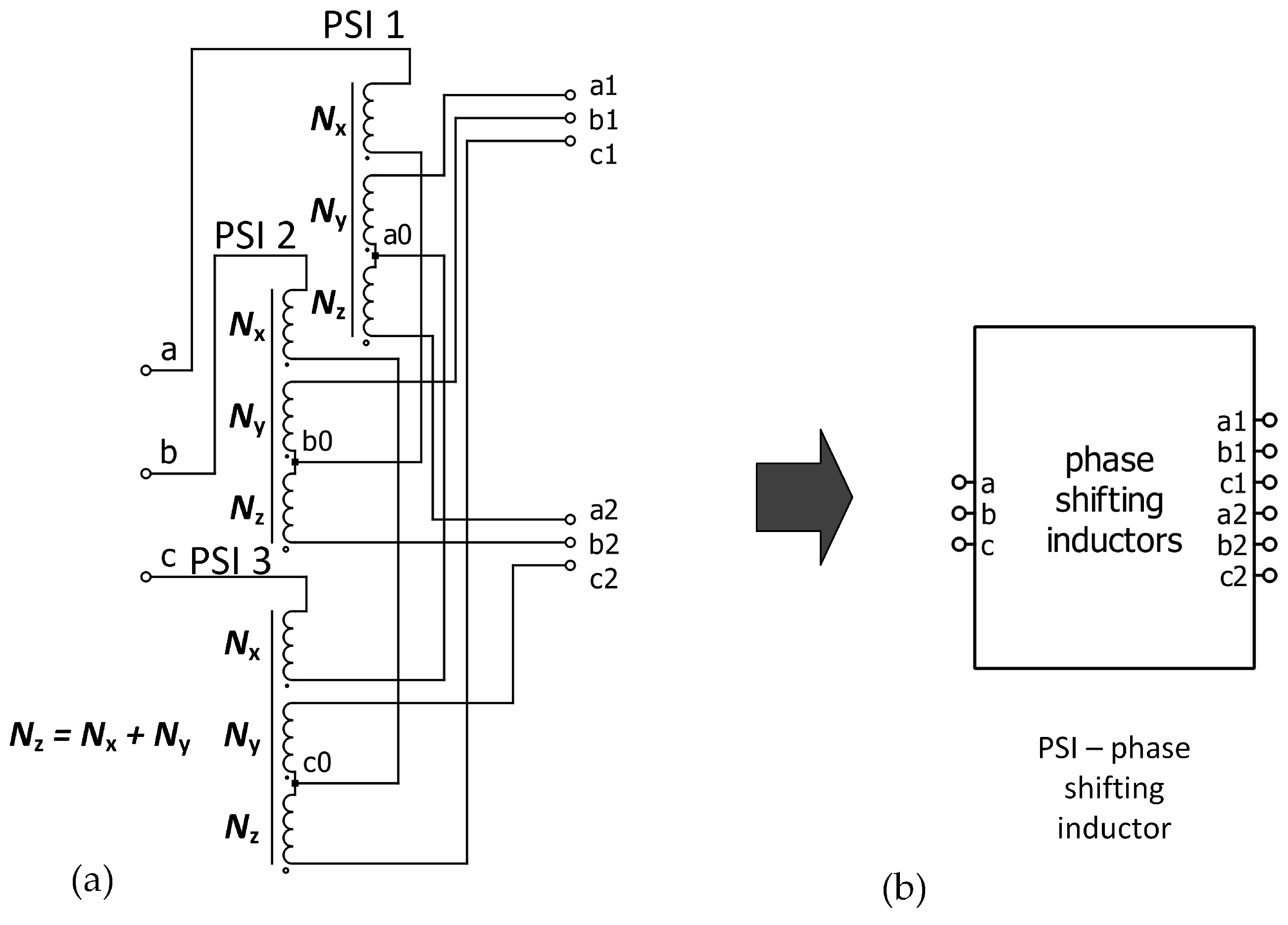
Magnetically coupled PSI perform a similar role to phase shifting transformers; however, they are characterised by a much lower power output and a more complex secondary winding system. The PSI configuration presented in Figure 1 enables the conversion of a three-phase voltage system to a six-phase system. This PSI consists of three independent magnetic cores equipped with windings denoted as N x , N y , N z , where:
N z = N x + N y .
Appropriate selection of the winding ratio creates two symmetrical three-phase voltage systems displaced by a defined phase angle at the PSI’s output. In general, the required phase shift angle ϕ is related to the number of converter’s pulses:
ϕ = 360 p = 2 π p ,
For instance, in the case of a 12-pulse rectifier, ϕ is equal to π 6 , while for a 24-pulse rectifier ϕ = π 12 . Applied PSI enables accurate phase-angle adjustment between the space vectors of the output voltages over a wide range. It depends directly on the ratio of the number of windings N y N x :
N y N x = s i n ϕ s i n ( π 3 ϕ ) .
The phase-shift angle is directly determined by the winding ratio. Therefore, deviations in real inductance values (Table 1) can affect the effective phase shift, leading to incomplete harmonic cancellation.
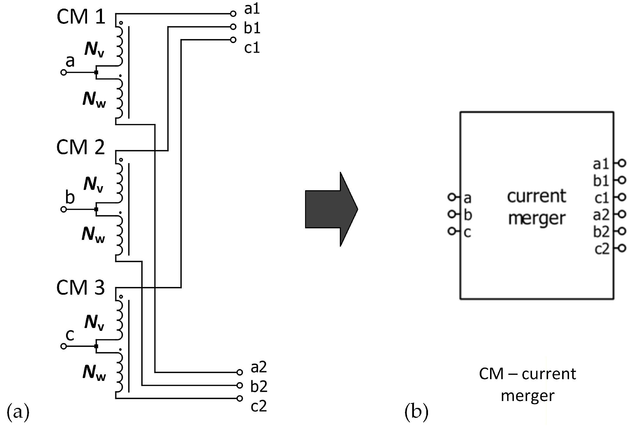
The structure of CM, which is presented in Figure 2 is simpler than PSI. In the context of multipulse rectifier design, the most significant feature of the CM circuit is the angle between phases a 1 and a 2 , b 1 and b 2 , as well as c 1 and c 2 . However, in contrast to the PSI circuit, each CM circuit functions independently of the others. This means that the CM circuit for a given phase does not affect the CM circuits of other phases. The calculation of the angle between phases for a given CM circuit is achieved through the utilisation of the following formula:
N v N w = 1 2 c o s ( ϕ ) .
The most elementary multi-pulse rectifier circuit that is utilised most frequently is the 12-pulse circuit. The implementation of this system can be achieved through the utilisation of either a PSI system or a transformer. The latter solution necessitates the connection of the rectifiers to a transformer equipped with three Ydy or Yyd windings. It is evident that Ydy or Yyd transformer configurations permit displacements that are equal to π / 6 or a multiple thereof. However, it should be noted that they do not permit arbitrary phase-angle shaping for voltages generated on the secondary side. Maintenance-free dry-type transformers, adapted to increased thermal losses, are typically used to power rectifiers with 12-pulse output voltages, while oil-immersed transformers are used in traditional traction substations. This paper focuses on PSI-based systems due to their properties described earlier in the text.
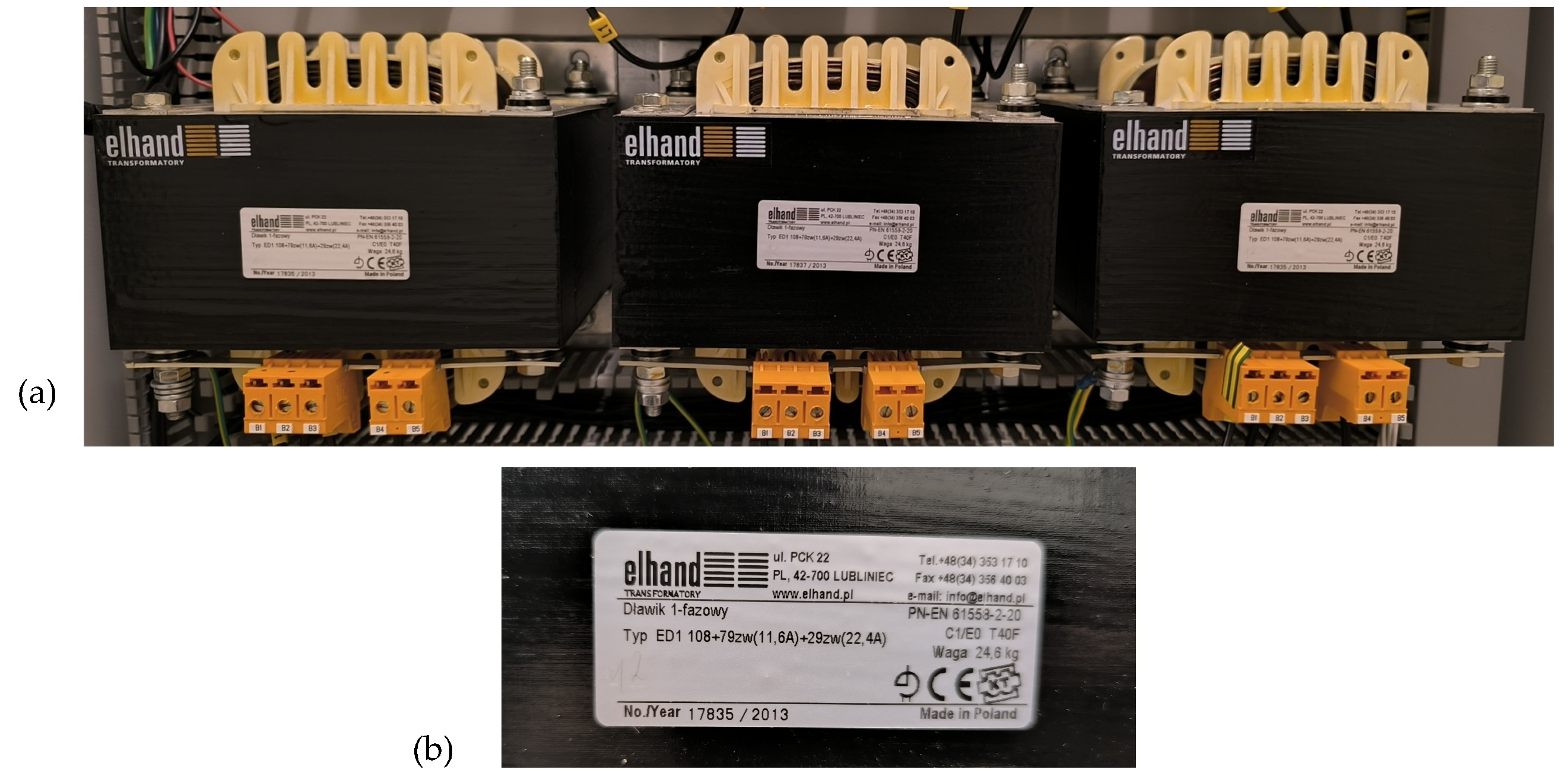
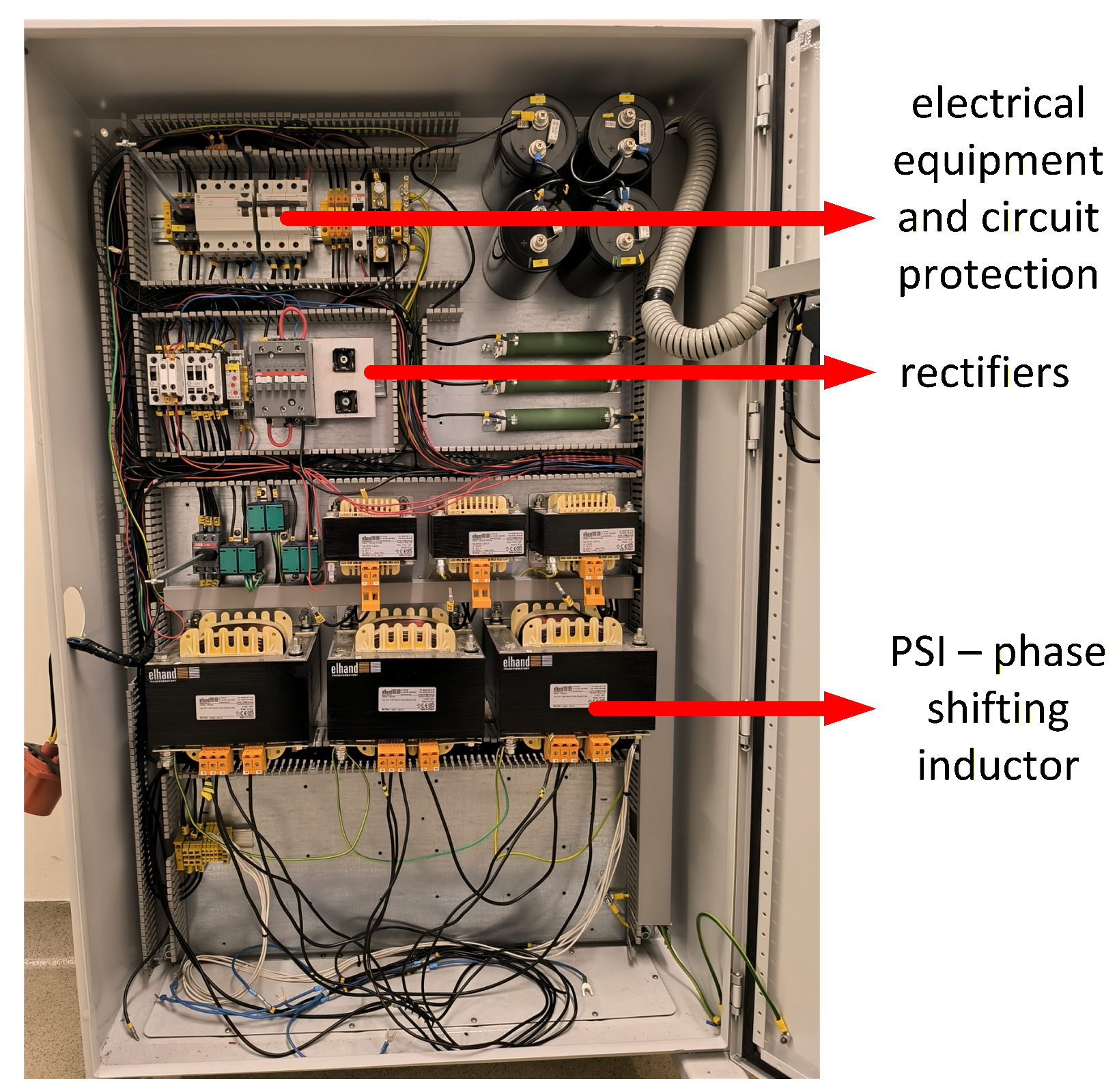
The experimental studies presented in this paper were conducted in the laboratory of Gdynia Maritime University. The conducted tests utilised an available PSI system with the following winding configurations: N x = 29 , N y = 79 , N z = 108 . The same configuration was also used in the simulation studies presented later in this paper (Section 3.2). Figure 3 shows a photo of the implemented inductors along with their parameters provided by manufacturer. Mains power is supplied to the N x winding, while the other two windings, N y and N z , are intended for connecting 6-pulse bridge rectifiers. The PSI were designed in accordance with the PN-EN 61558-2-20 standard [30].
The rated supply voltage is 400 V, and the maximum voltage is 750 V. The PSI system is designed for a rated current of 22.4 A. Table 1 summarizes the individual inductances of the PSI circuits measured with RLC bridges available in the laboratory at a frequency of 50 Hz. The inductances shown in Table 1 are averages obtained from a series of measurements, and the standard deviation of the repeat measurements did not exceed 0.5 %.
Observed variations in inductance values between phases can introduce asymmetry, which results in unequal current sharing and increased harmonic content in the input current. Since current harmonic cancellation in multi-pulse rectifiers relies on precise phase displacement, any deviation from the ideal angle increases residual harmonics, thereby increasing the value of THD factor.

3. Parallel Operation of Multi-Pulse Rectifiers Developed with Magnetically Coupled Inductors

The circuit of PSI presented in Figure 1 has been utilised to construct multi-pulse rectifiers: 12-, 18-, 24-, and 36-pulse [27]. However, both 18- and 36-pulse rectifiers also require current CM, whose configuration is presented in Figure 2. A common feature of all these converter systems is the parallel operation of the rectifier bridges. This means that, regardless of the rectifier version, the same value of DC output voltage can be achieved for the same mains voltages, differing in the number of pulses. Nevertheless, an increase in the number of converter pulses results in an enhancement of the DC current-carrying capacity, accompanied by a reduction in the harmonic content of the current drawn from the mains.
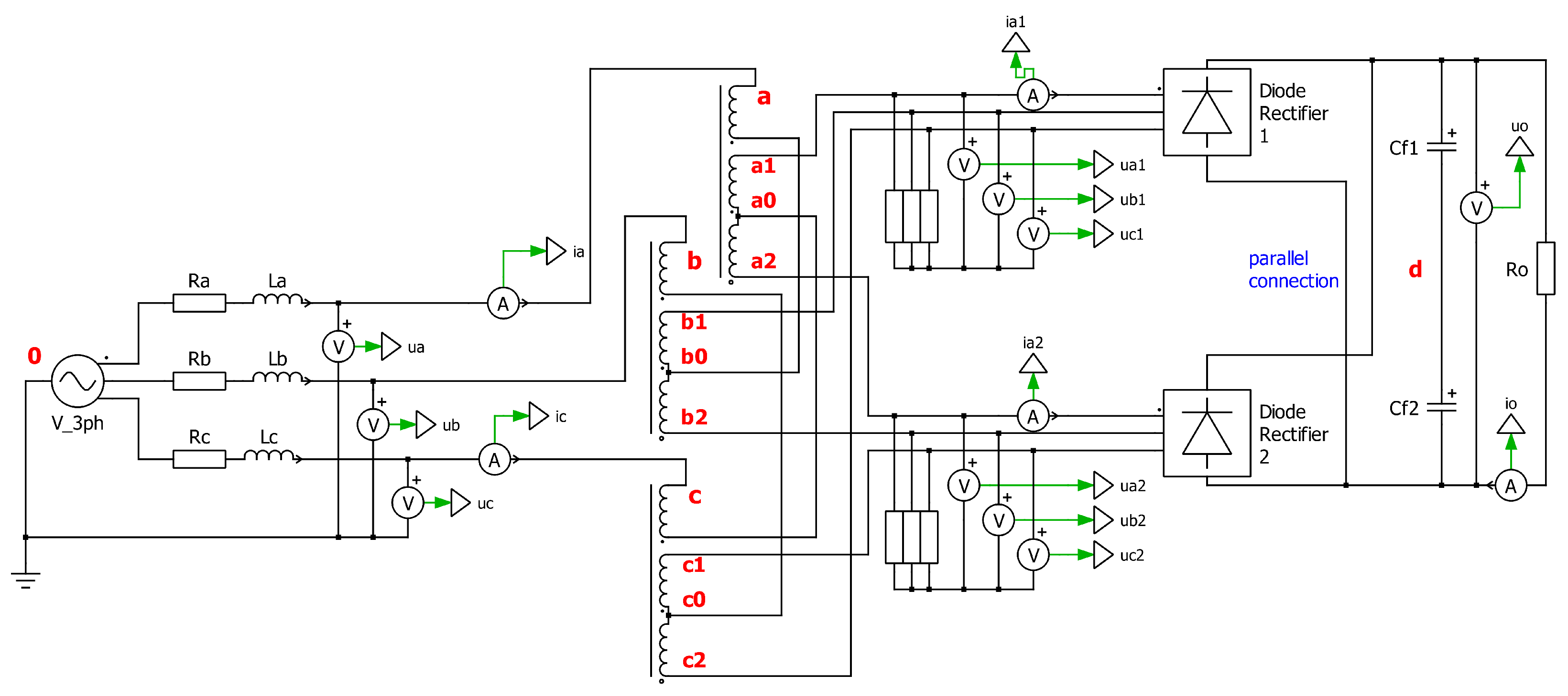
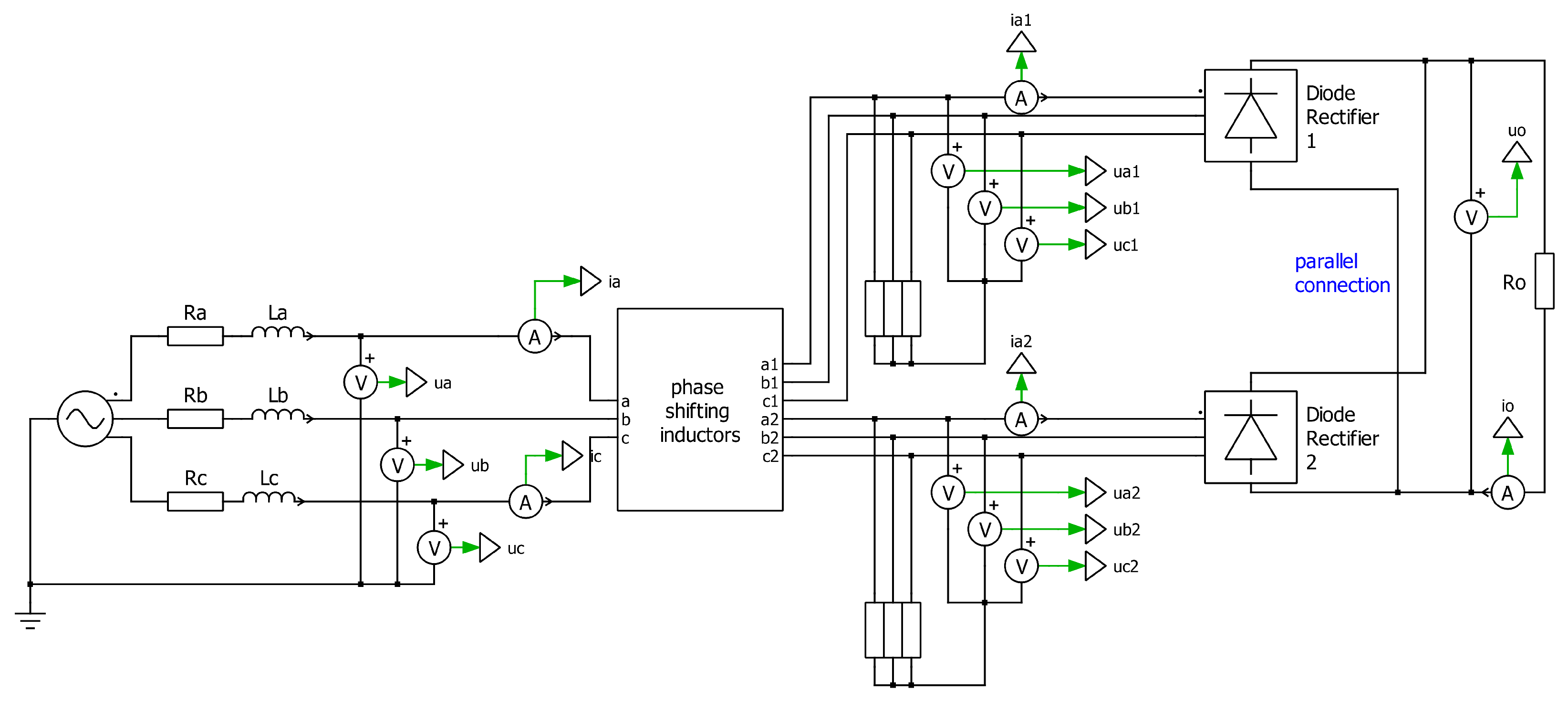
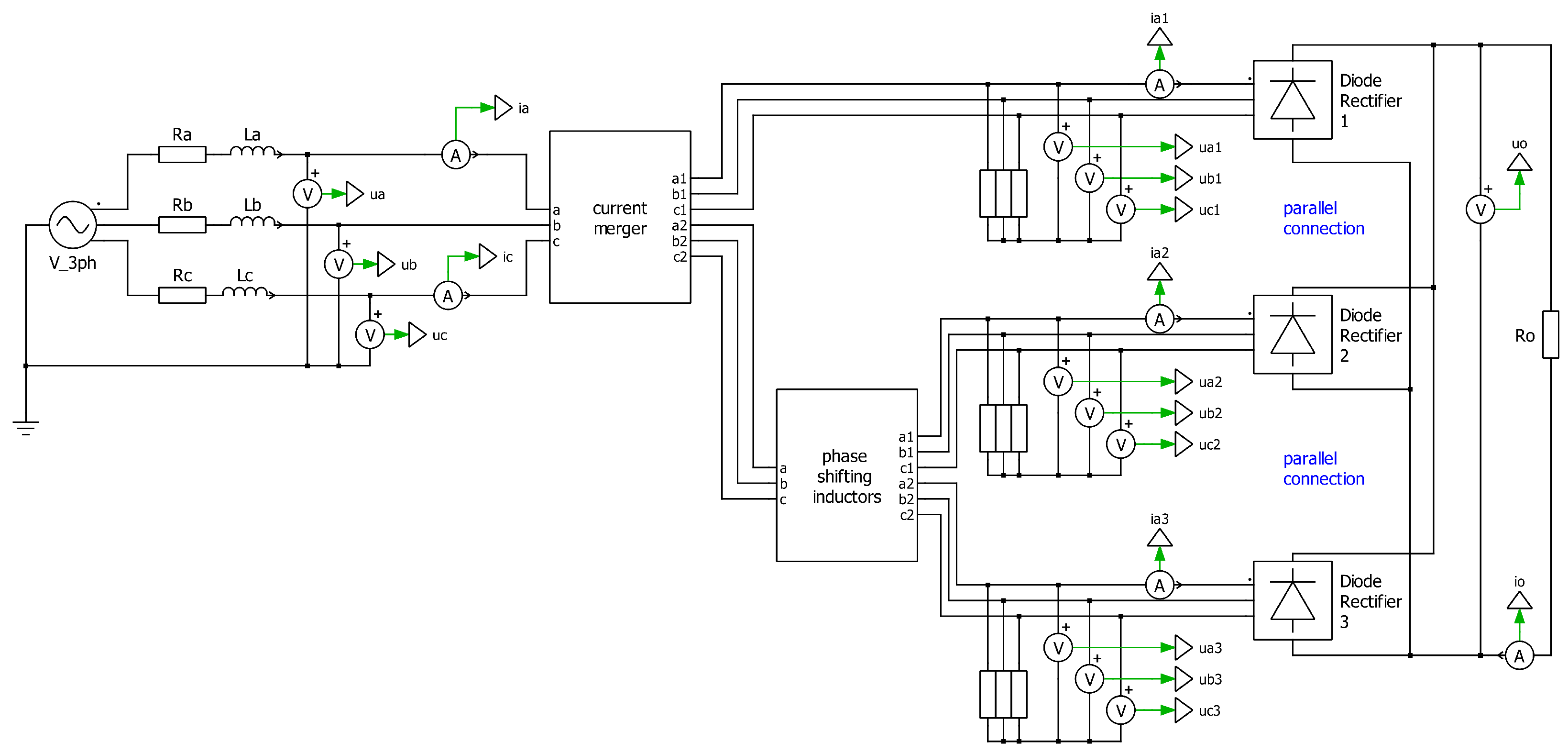
This section provides an analysis of PSI as a system that converts a three-phase system into a six-phase system. The analysis presented below demonstrates how the voltage is shifted in phase for the construction of multi-pulse rectifiers. The analysis is conducted in the context of the simplest configuration, which is a 12-pulse rectifier shown in Figure 4.
The voltages between nodes a, b, c, and node 0 are obtained by first determining the zero voltage component u 0 d between nodes 0 and d, as defined by
u 0 d = u d a + u d b + u d c 3 .
Therefore, the voltages between nodes a, b, c, and node 0 are determined in the following manner:
u a = u 0 d + u d a , u b = u 0 d + u d b , u a = u 0 d + u d c .
The voltages present between points “a”, “b”, “c” and “d” are derived from the following equations:
u d a = u d a 1 [ N x y 1 ] u a 2 a 1 [ N x y 2 ] u c 2 c 1 , u d b = u d b 1 [ N x y 1 ] u b 2 b 1 [ N x y 2 ] u a 2 a 1 , u d c = u d c 1 [ N x y 1 ] u c 2 c 1 [ N x y 2 ] u b 2 b 1 ,
where
N x y 1 = ( N x + N y ) N x + 2 N y , N x y 2 = N x N x + 2 N y .
The design procedure of the PSI system depends on its total apparent power, defined as the arithmetic average of the power ratings of the windings of an equivalent two-winding transformer. This parameter can be evaluated assuming that the core magnetic flux is excited by a sinusoidal voltage source with angular frequency ω . The detailed analysis of the overall power calculation, however, is not addressed in this paper.

3.1. Simulation Studies—Basic Assumptions and Parameters

All simulation tests were conducted using PLECS 5.0 (Piecewise Linear Electrical Circuit Simulation), a tool dedicated to power electronics analysis. PLECS is specialised software distinguished by its use of a piecewise linear approach and accurate detection of switching events, which enables fast and stable simulations.
The simulation cases, in conjunction with the primary parameters, are delineated in Table 2. The parameters, as well as scenarios, were the same for all cases. Tests were performed for a phase-to-phase voltage of 400 V and 50 Hz, with each system loaded with two resistances: 100 Ω and 10 Ω . The utilisation of two distinct loads is of paramount importance, as it imposes two markedly disparate operating states on the rectifiers. Decreasing the resistance value from 100 Ω to 10 Ω was forced at t = 1 s, which is manifested in the waveforms by a rapid change in voltage and current.
First case (C1) contained in the Table 2 is well established in the literature, common, and very popular. Therefore, this paper does not present its topology and particular graphical results, but only final RMS and THD values included in Table 3. Nevertheless, considering this case is important to provide a better comparison of particular multi-pulse rectifiers.
The conclusions of the simulation results of parallel operation of the considered rectifiers are presented in Section 3.5. It also provides detailed information on the RMS and THD values of particular signals, which are compared in Table 3.

3.2. Simulation Studies of Uncontrolled and Controlled 12-Pulse Rectifiers—Cases C2 and C3

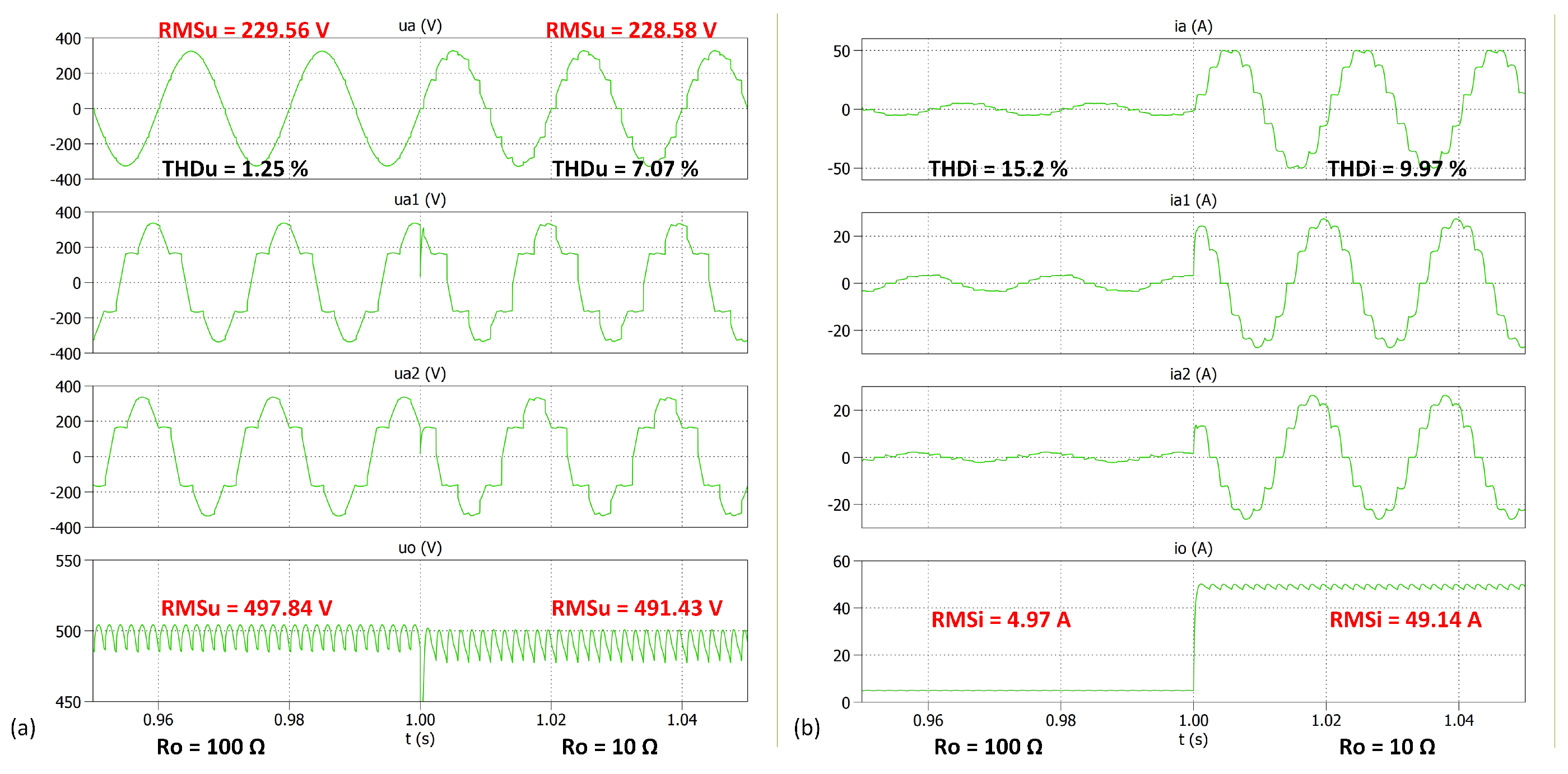
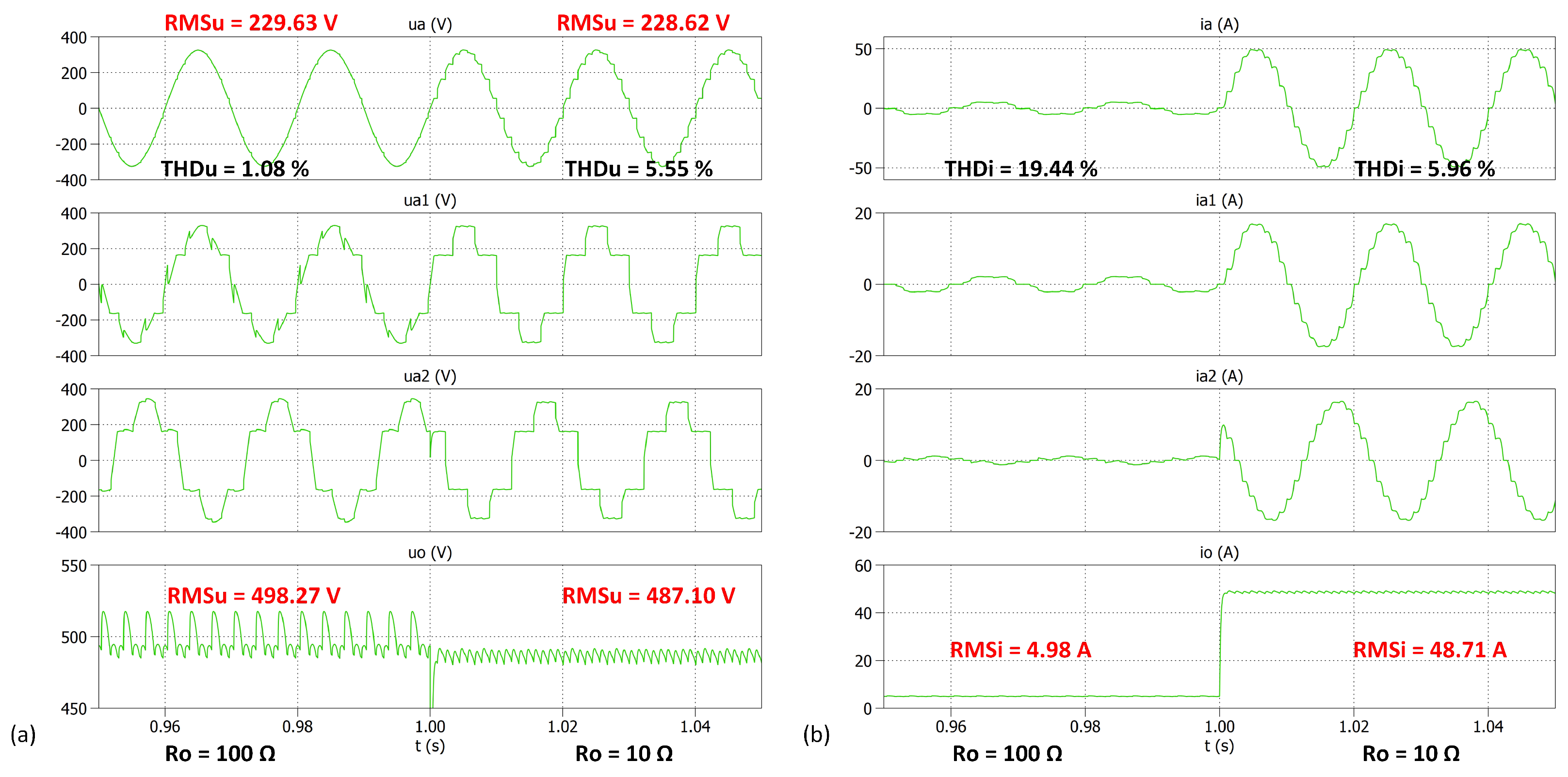
Based on the schematic of the 12-pulse rectifier presented in Figure 4, a simulation model of the system was developed (Figure 5), and simulation tests were conducted (case C2). Voltage and current waveforms obtained during the test are presented in Figure 6.
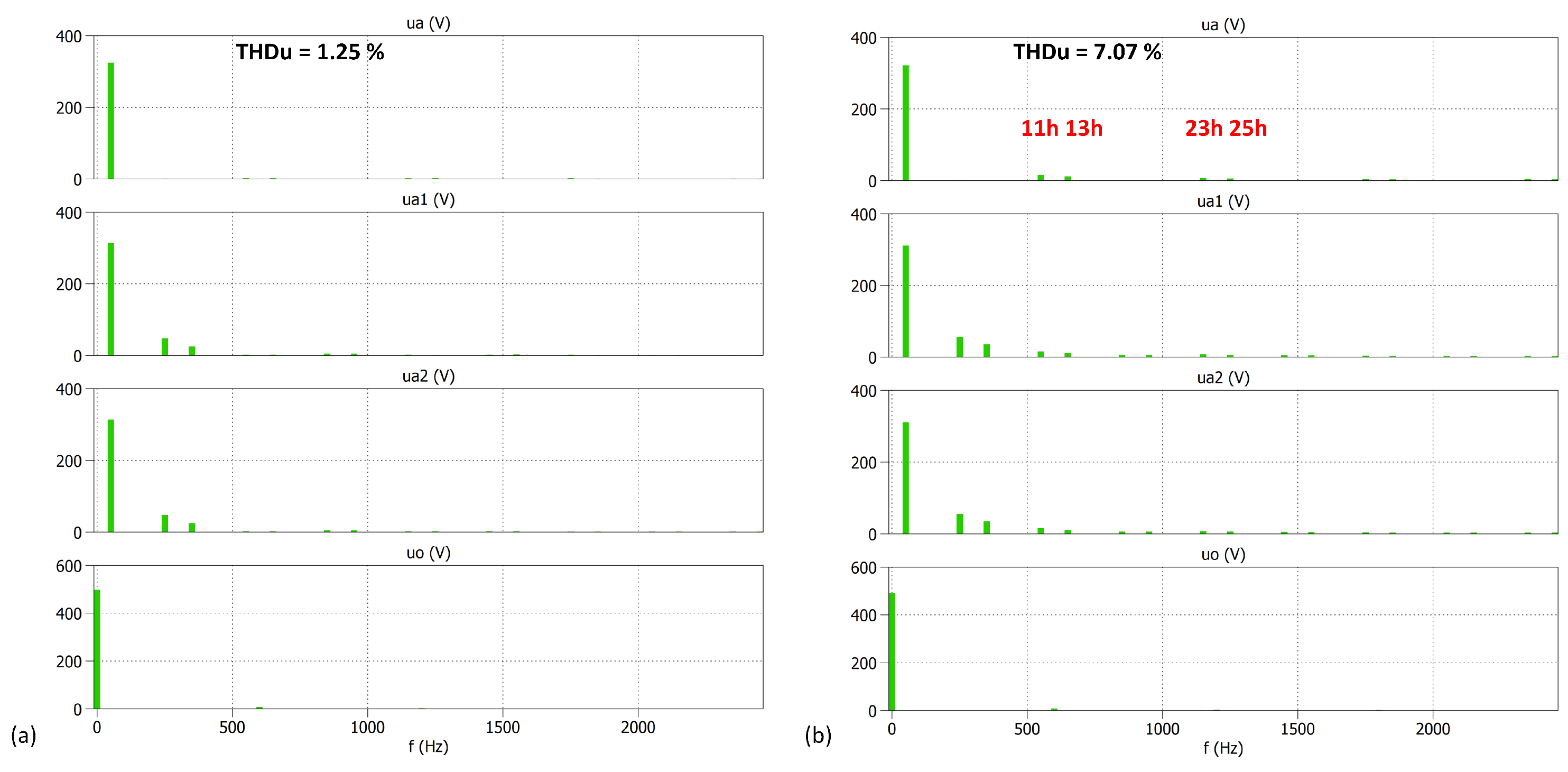
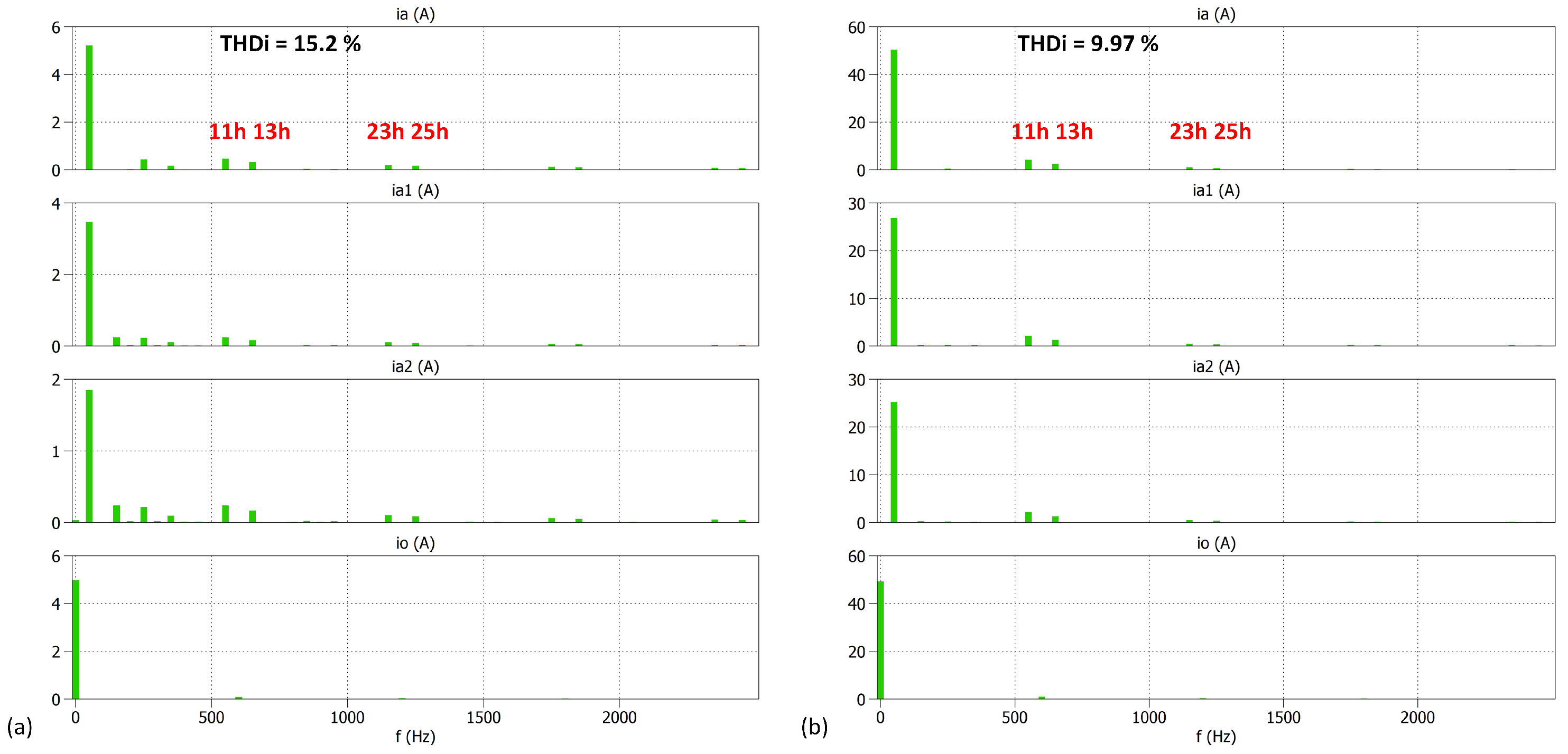
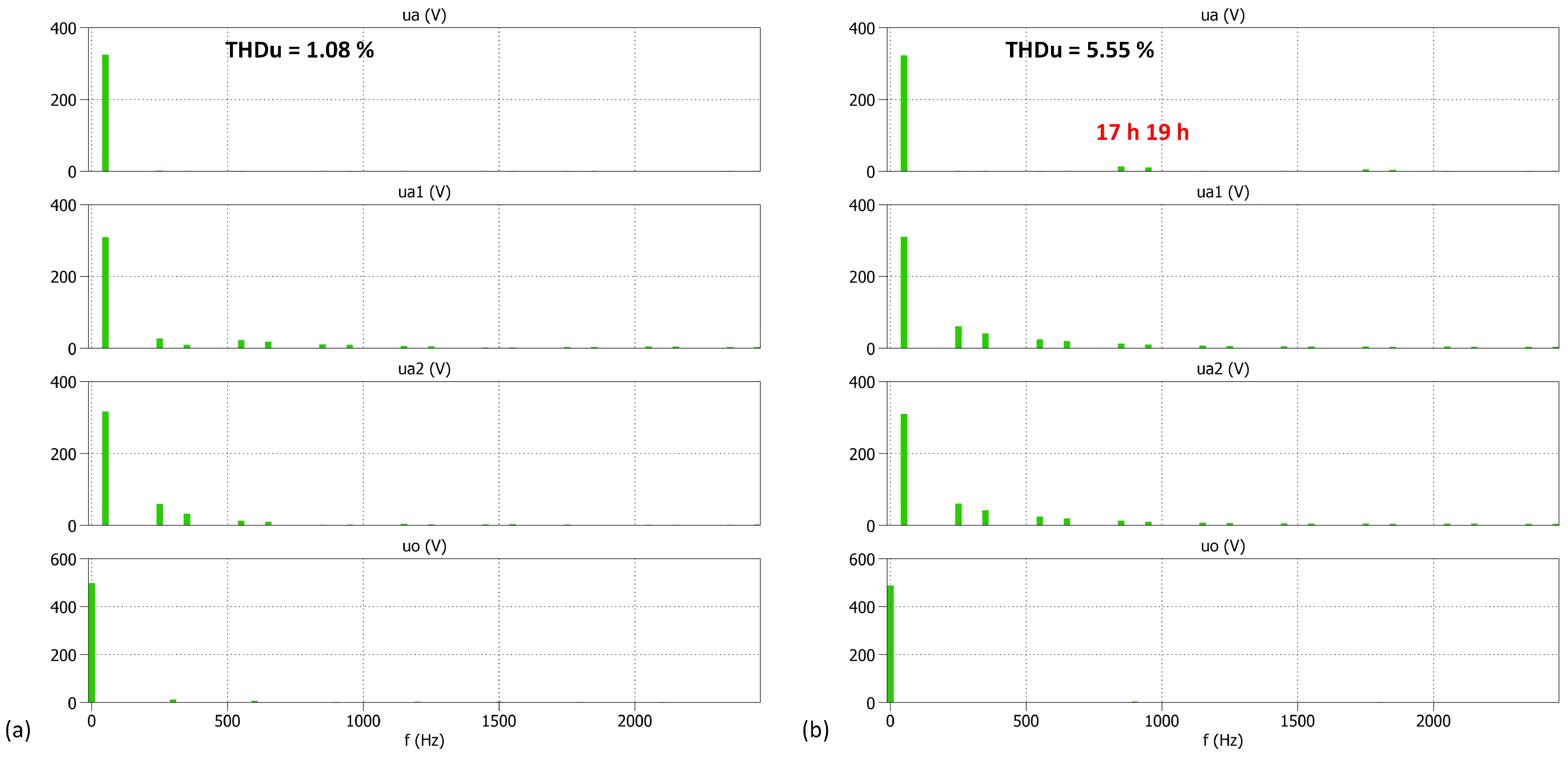
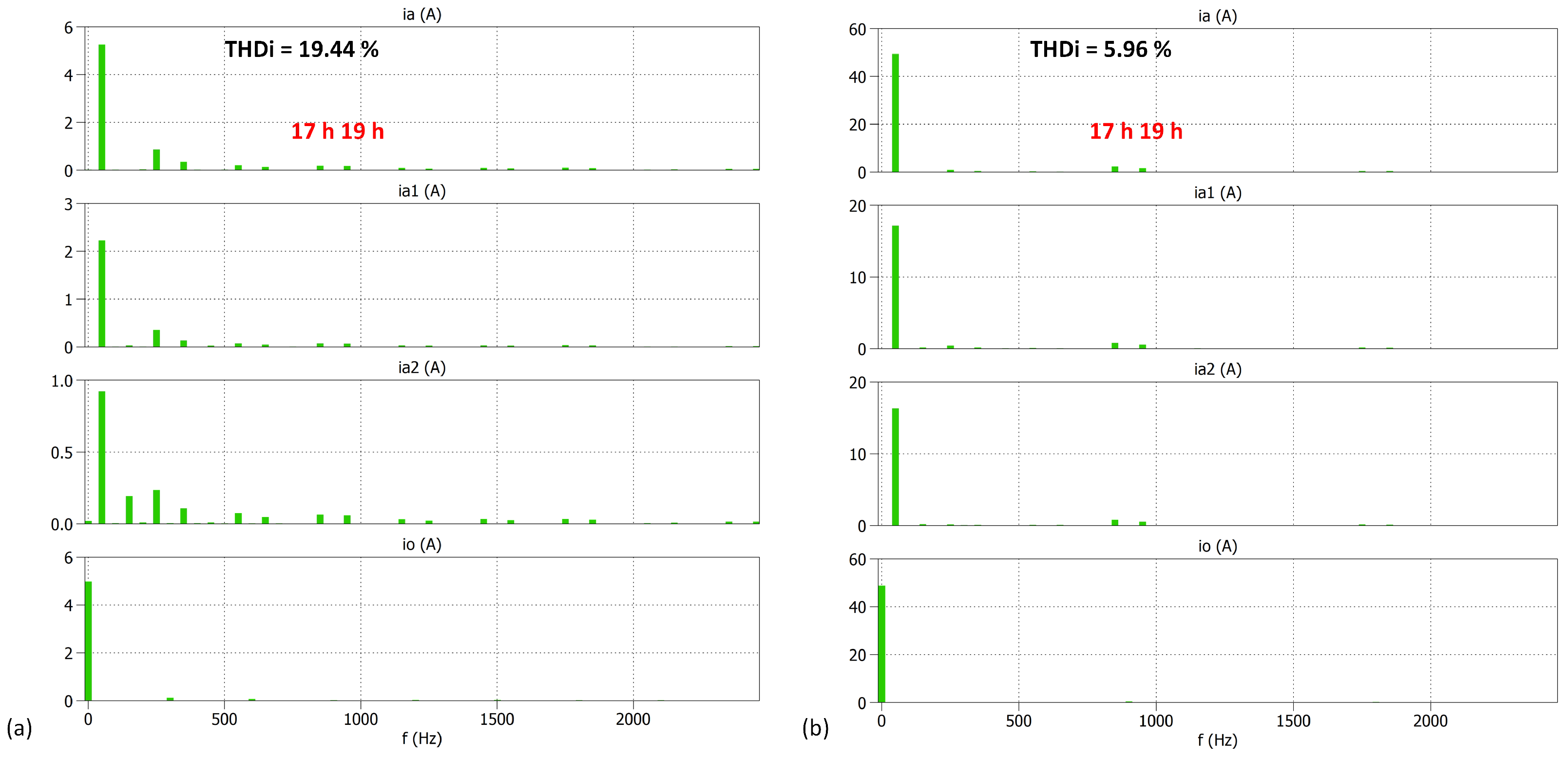
The phase voltage of the grid, as well as current waveforms measured between the grid and the PSI and between the PSI and the rectifier bridges, show characteristic 12 pulses. Figure 7 and Figure 8 illustrate the voltage and current frequency spectra for the rectifier under study.
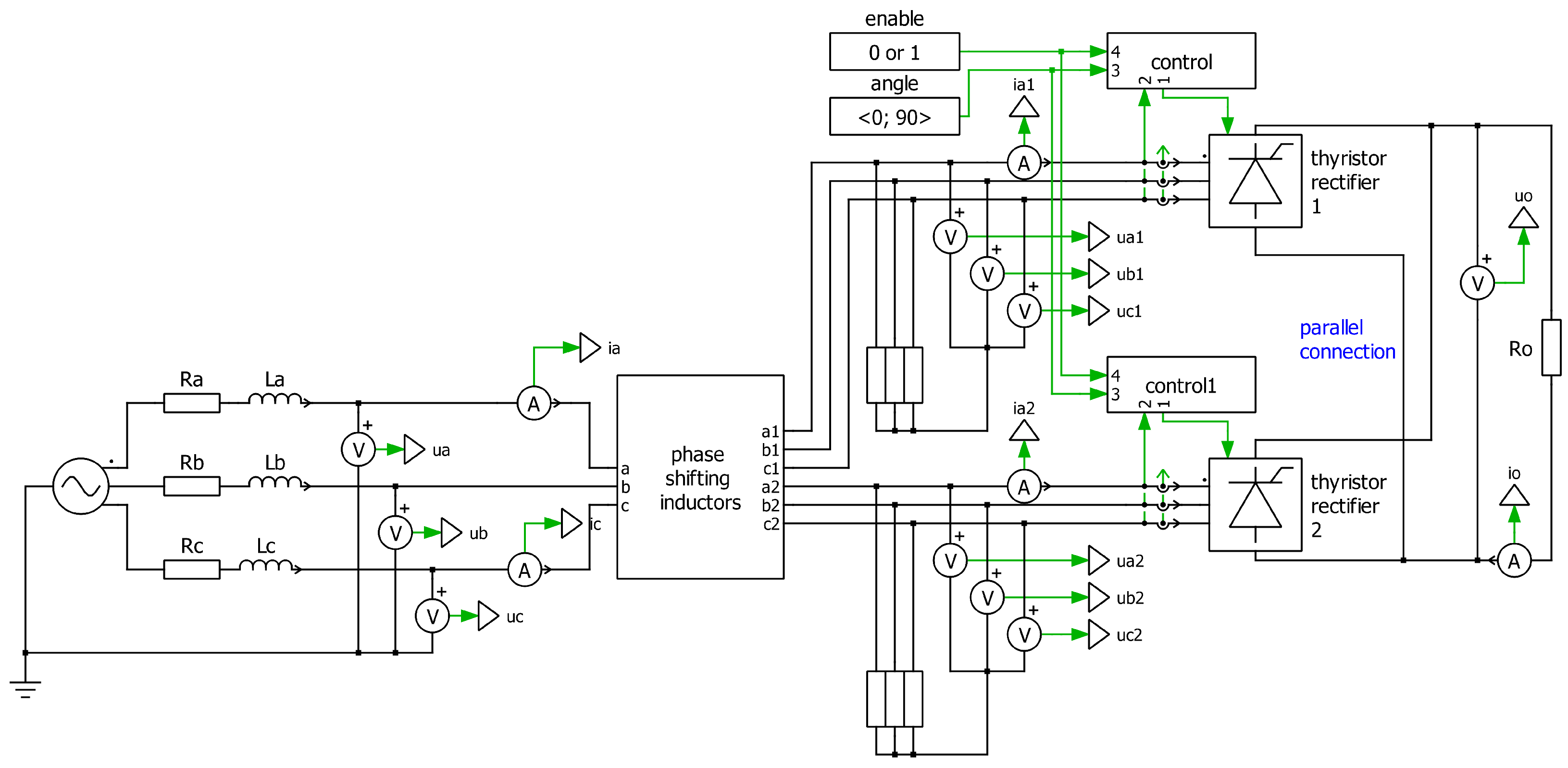
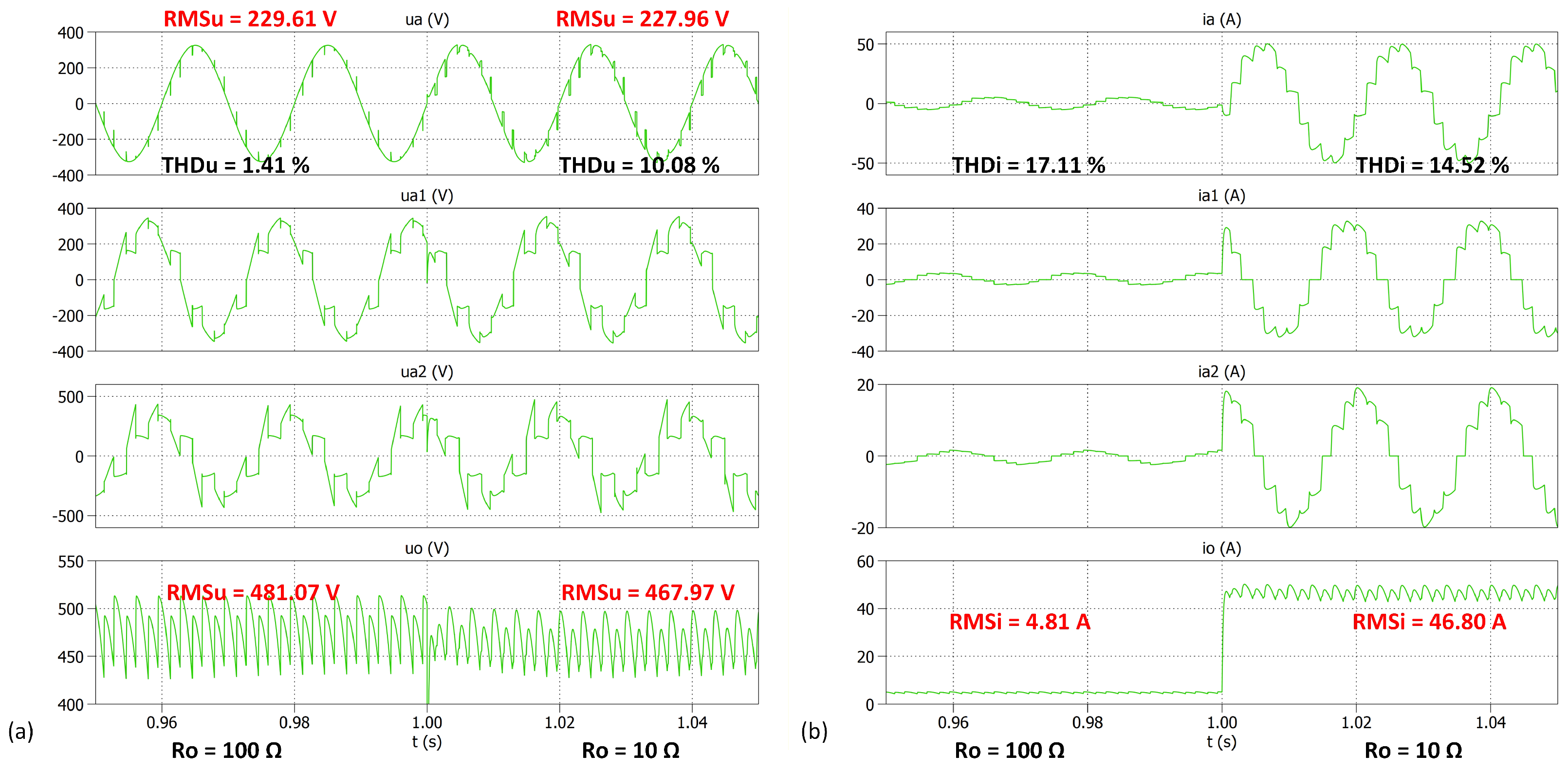
In the course of the simulation and subsequent experimental studies, the operation of a controlled 12-pulse rectifier was also considered (case C3). The system model is illustrated in the Figure 9. The studies were conducted for a thyristor firing angle of α = 40 .
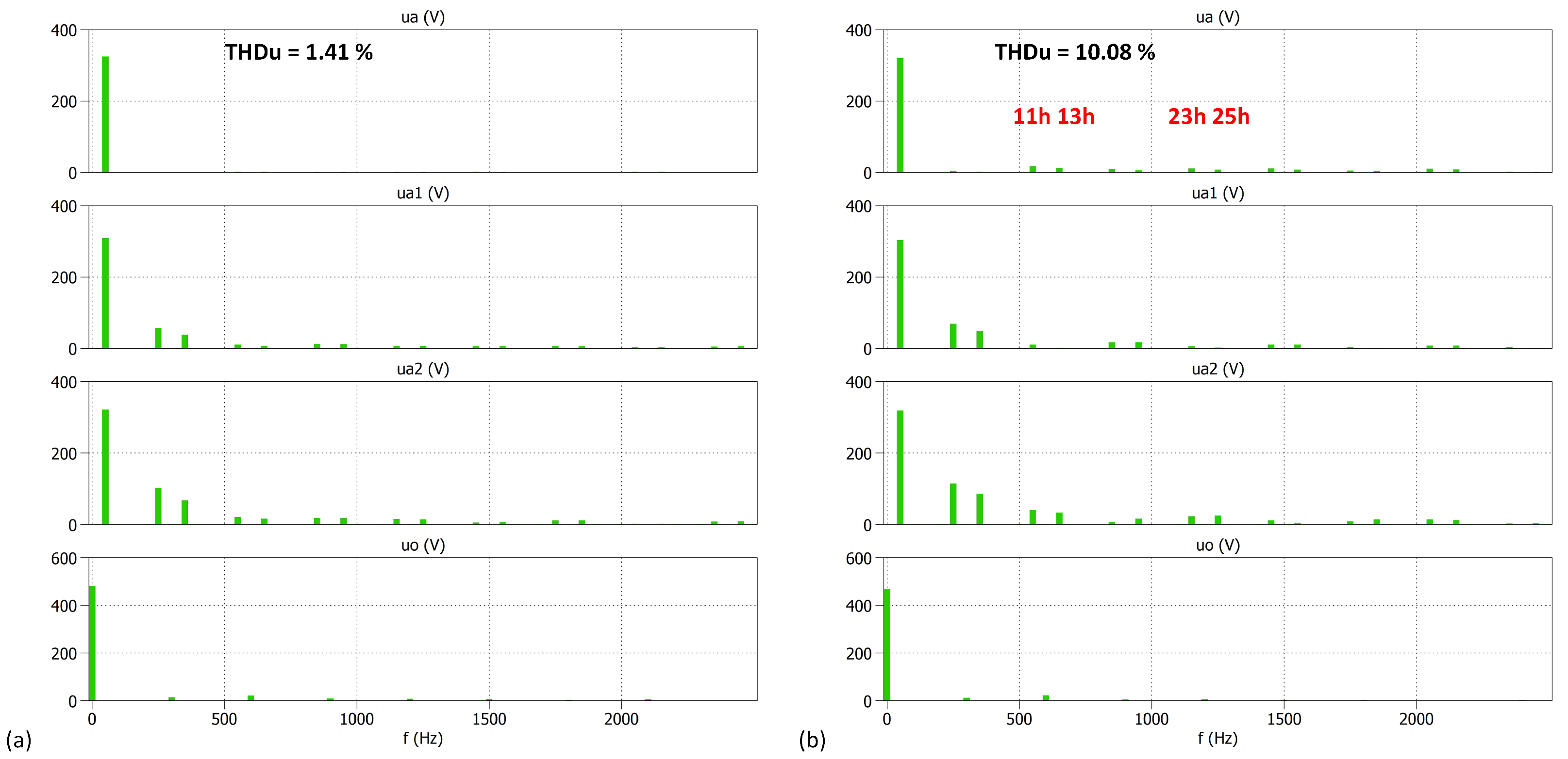
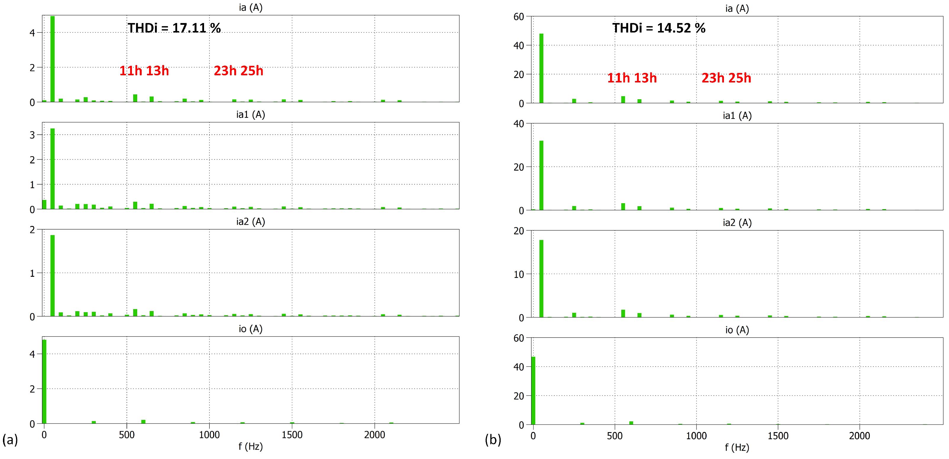
The utilisation of thyristors facilitates the regulation of DC voltage; however, it necessitates the incorporation of a control circuit. This is problematic due to the distorted voltage waveforms present before the bridge rectifiers. This complicates synchronisation with the bridge supply voltage and the accurate identification of the natural commutation point. Furthermore, an increase in the number of pulses results in a decrease in the range of control of the output DC voltage. Concurrently, the advancement of the rectifier’s topology is escalating, which is resulting in increased costs. Consequently, converters with more than 12 pulses, as discussed in this paper, are analysed in their uncontrolled versions. Figure 10 illustrates the waveforms of selected voltages and currents of a 12-pulse controlled rectifier, while Figure 11 and Figure 12 present their frequency spectra.

3.3. Simulation Studies of Uncontrolled 18-Pulse Rectifiers—Case C4

In the development of rectifiers characterised by a high number of pulses, it is imperative that the windings are selected to achieve the requisite angles for the specific circuit comprising magnetically coupled inductors. Figure 13 presents the 18-pulse rectifier constructed with the usage of CM and PSI. In accordance with Equation (6), the 18-pulse rectifier requires a shift angle equal to ϕ = π / 9 = 20 between particular bridge modules. This is achieved by the application of CM, which realises the angle shift of 20° on the first stage, and the utilisation of PSI on the second stage with the same shift angle. To obtain this, the authors implemented the required inductors with the following number of turns: N v = 67 , N w = 126 , N x = 126 , N y = 236 , N z = 362 . The results of simulation studies are presented in Figure 14, Figure 15 and Figure 16.

3.4. Simulation Studies of Uncontrolled 24-Pulse Rectifiers—Case C5

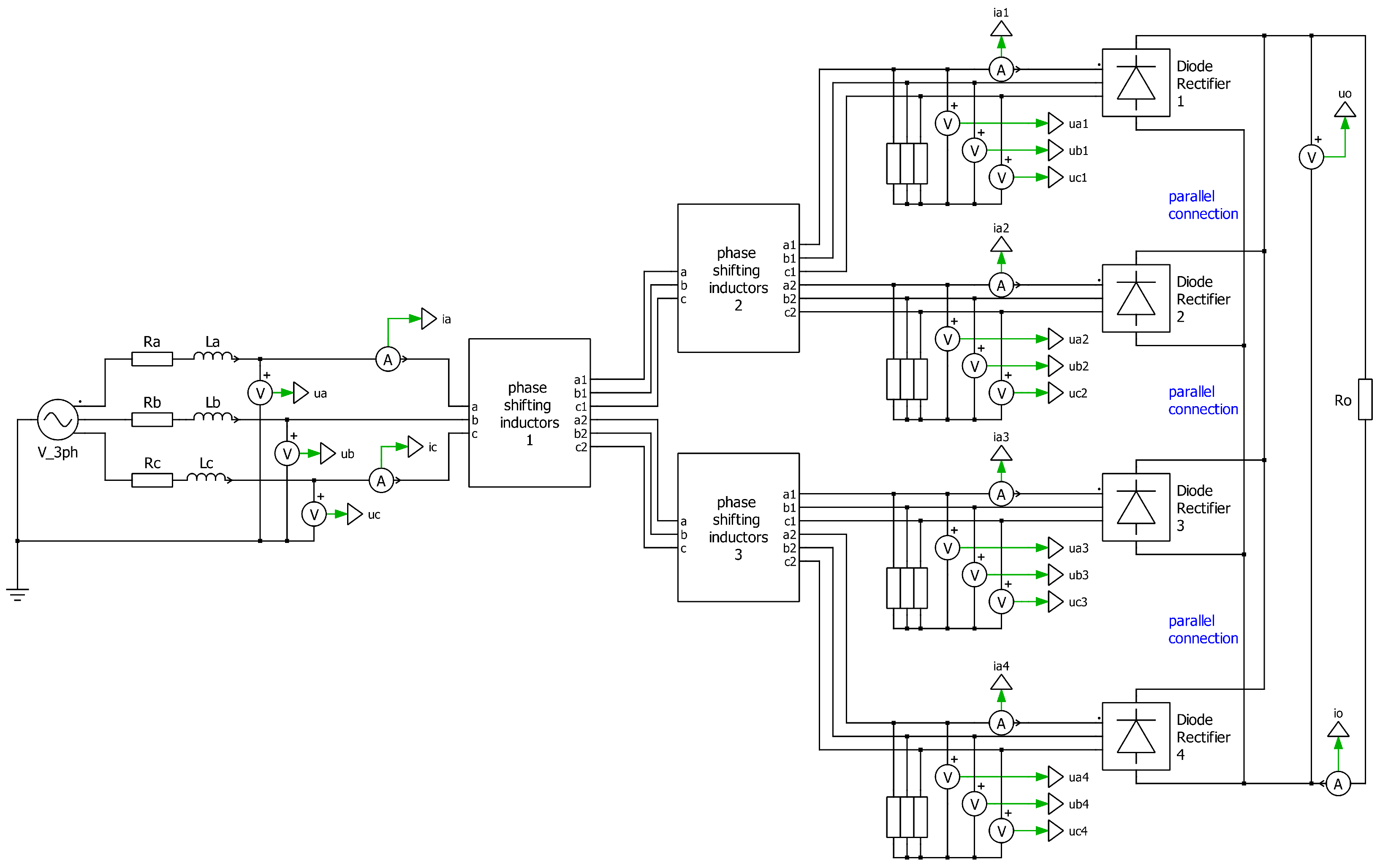
The topology of a 24-pulse rectifier implies the application of four 6-pulse bridge modules, which have to be phase-shifted by 15 degrees. Therefore, a four-phase system is required. This is realised by PSI forming two stages. The phase shift in the first stage is ϕ = 7 . 5 , whereas in the second stage it is ϕ = 15 . Each stage employs the same PSI circuit, differing only in the number of turns. In the presented simulation studies, this effect was achieved by selecting the following number of turns for the PSI in the first stage: N x = 23 , N y = 138 ,   N z = 161 , and for the PSI in the second stage: N x = 71 ,   N y = 195 ,   N z = 266 . Figure 17 presents a schematic representation of a 24-pulse rectifier constructed with PSI. In accordance with the schematic, a simulation model was developed in PLECS.
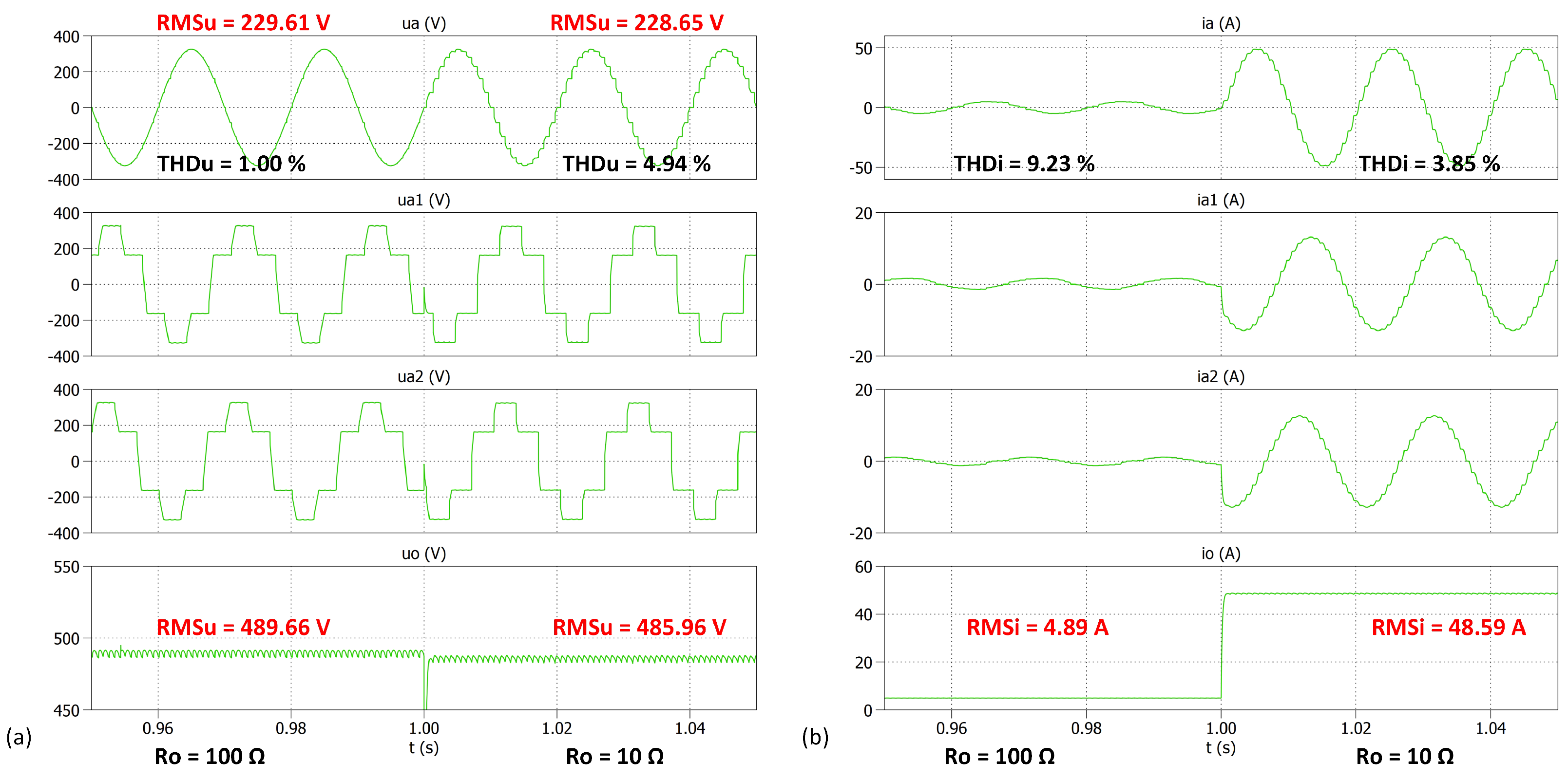
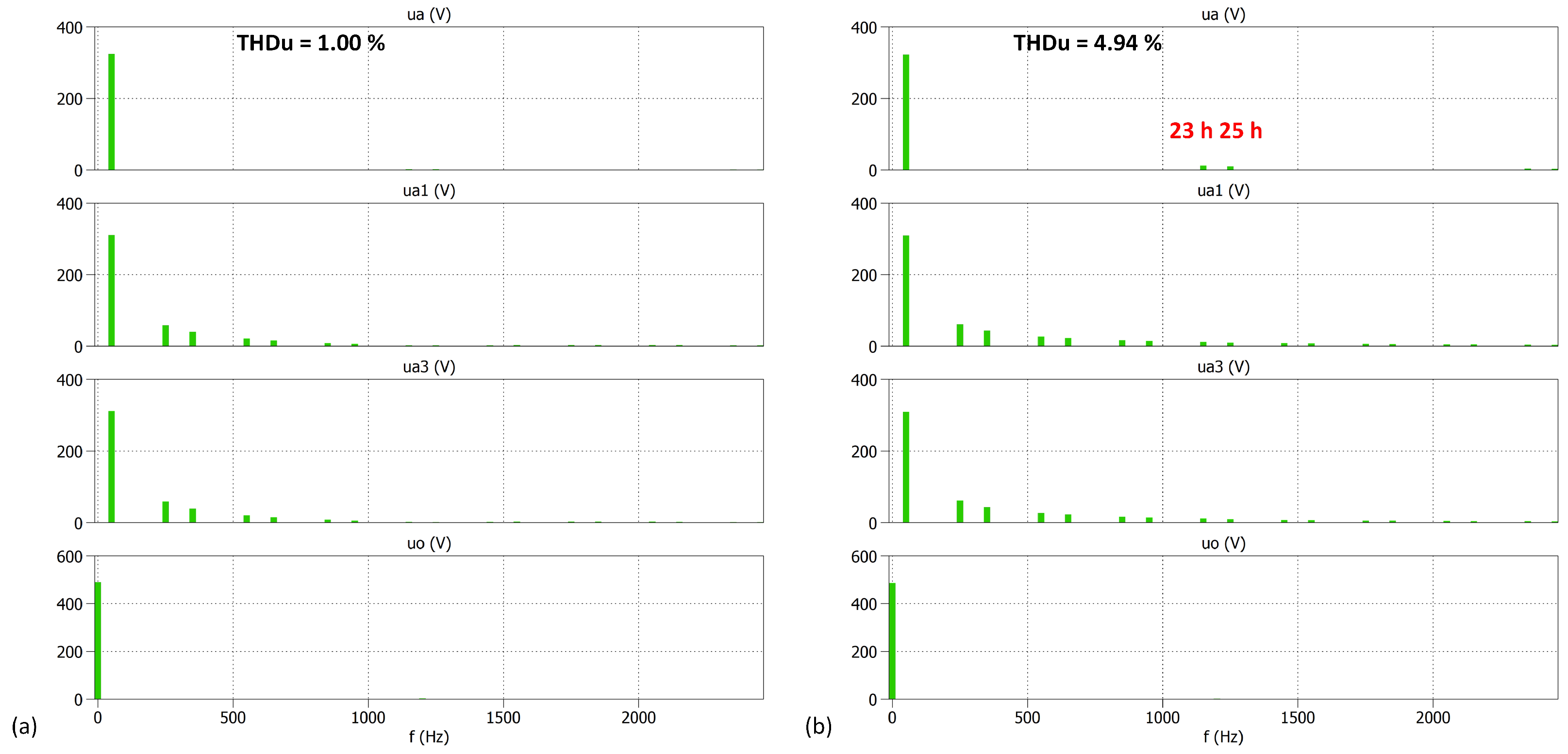
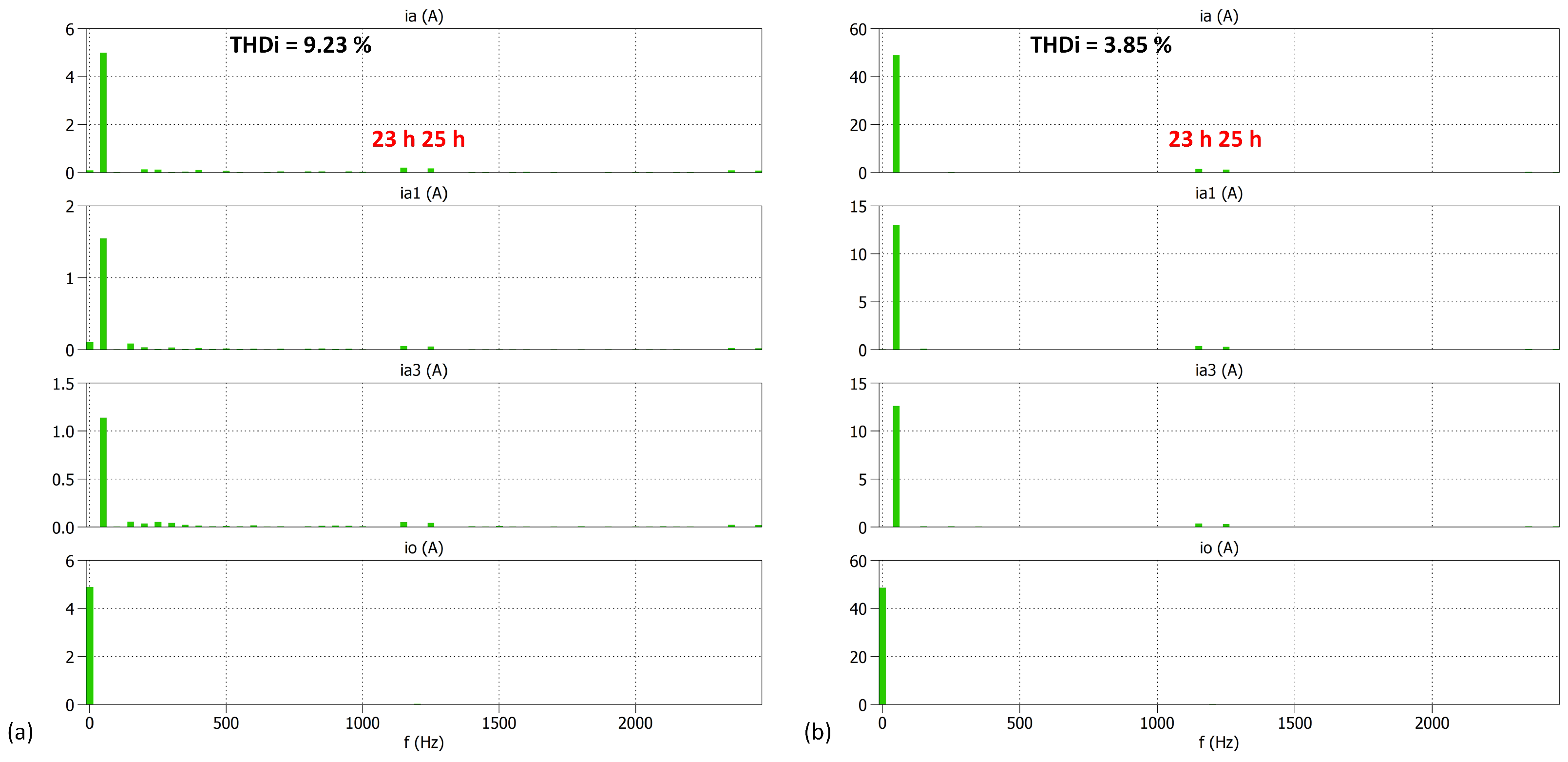
The simulation results encompass selected voltage and current waveforms presented in the Figure 18 and their frequency spectra shown in Figure 19 and Figure 20.

3.5. Summary of Simulation Studies of Selected Multi-Pulse Rectifier Topologies with Magnetically Coupled Inductors

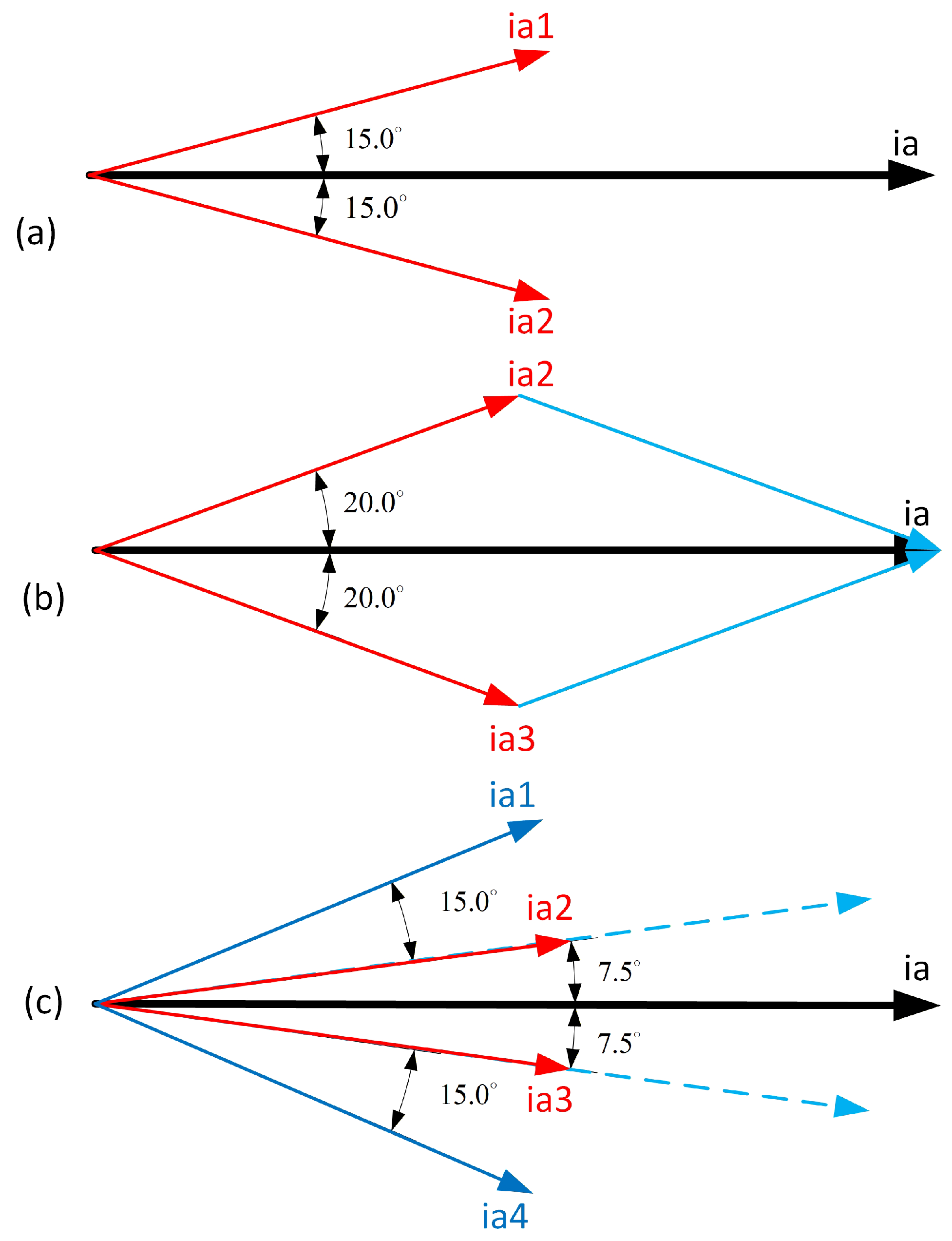
Despite the fact that particular multi-pulse rectifiers exhibit differences in their topologies, it is possible to draw a number of conclusions about their common characteristics, properties, and dependencies. Figure 21 illustrates the current spatial vectors for the 12-, 18-, and 24-pulse rectifiers developed with magnetically coupled inductors. The vectors shown in Figure 21 represent an idealised case assuming perfect symmetry and exact phase shifts. In practice, deviations in inductance values (Table 1) may lead to slight asymmetry of phase angles and incomplete harmonic cancellation.
Table 3 summarises the parameters describing the voltage and current waveforms included in the rectifier simulation studies. The THD coefficient given in the table encompasses the range of 50 harmonics as it covers both IEEE 519-2014 and PN-EN 50160:2010/AC:2011 standards [31] and has been calculated according to the equations:
T H D u = h = 2 50 U h 2 U 1 · 100 % , T H D i = h = 2 50 I h 2 I 1 · 100 % .
The simulation results of uncontrolled and controlled multi-pulse rectifiers developed with magnetically coupled inductors (CM and/or PSI) demonstrate a significant feature: the load voltage and current waveforms contain a particular number of pulses consistent with the number of the rectifier’s pulses. The higher the number of pulses, the smaller the ripples in the DC voltage and current. The same number of pulses consistent with the rectifier’s pulses is observed in the supply phase voltage and current waveforms. Another phenomenon that can be observed is the fact that voltage and current waveforms, particularly between the PSI and the rectifiers as well as the PSI and the grid, are contingent on the load. At low load currents, the magnetic coupling is insufficient to maintain the designed phase relationships, which leads to degradation of harmonic cancellation and increased distortion. The effect of this relationship weakens with an increase in the number of the converter’s pulses.
Table 3. Parameters describing the voltage and current waveforms included in the rectifier simulation studies.
Simulation Case/Rectifier’s Topology
ParameterC1/6-Pulse,
Uncontrolled
C2/12-Pulse,
Uncontrolled
C3/12-Pulse,
Controlled
C4/18-Pulse,
Uncontrolled
C5/24-Pulse,
Uncontrolled
R o 10 Ω 100 Ω 10 Ω 100 Ω 10 Ω 100 Ω 10 Ω 100 Ω 10 Ω 100 Ω
u a THD [%]9.971.897.071.2510.081.415.551.084.941.00
RMS [V]228.17229.77228.58229.56227.96229.61228.62229.53228.65229.61
u 1 a THD [%]--22.5217.2229.4923.8326.6314.2628.4324.67
RMS [V]--225.85224.97223.99224.42226.83220.44227.65226.52
u o RMS [V]521.82536.51491.43497.84467.97481.07487.10498.27485.96489.66
i a THD [%]25.9528.89.9715.214.5217.115.9619.443.859.23
RMS [A]41.834.3635.753.7334.203.5534.923.7834.603.53
i 1 a THD [%]--9.7413.714.5718.116.2818.303.839.59
RMS [A]--19.072.4822.842.3512.141.599.201.10
i o RMS [A]52.185.3749.144.9746.804.8148.714.9848.594.89
Figures -Figure 6, Figure 7 and Figure 8Figure 10, Figure 11 and Figure 12Figure 14, Figure 15 and Figure 16Figure 18, Figure 19 and Figure 20
The analysis of the obtained frequency spectra of the AC voltages and currents has revealed the presence of harmonics that are characteristic of particular converters, as demonstrated in Equation (2). On the other hand, when the current value is relatively low ( R o = 100 Ω ), the frequency spectra also comprise non-characteristic harmonics. The occurrence of these frequencies is attributable to the non-linearities inherent within the system. The content of such harmonics is found to be similar in each case of resistance value, and their absolute quantity is relatively low. Nevertheless, when the RMS current value decreases, the relative content of those harmonics increases. When analysing tests in which the resistance was high and the RMS current value was low, the level of the discussed harmonics was the same as the level of characteristic harmonics. Nevertheless, the case of R o = 100 Ω with an RMS current of about 4A considered in the research is uncommon in the industry. This is why further conclusions are drawn on the basis of the case of R o = 10   Ω .
The findings indicate that an increase in the number of rectifier pulses has been shown to decrease distortions in the voltage and current waveforms from the sinusoidal shape. This, in turn, results in a lower THD coefficient value and, consequently, improved quality of electrical energy. However, this dependency is greatest when comparing 6- and 12-pulse rectifiers since the latter is characterised by T H D u 2.6 times lower and T H D i 1.4 times lower than for the 6-pulse converter. Further increases in rectifier pulses result in a lower decrease in THD value, diminishing with the number of pulses. On the other hand, the highest number of pulses requires a more sophisticated circuit configuration, a higher quantity of necessary modules, and, consequently, the elevated expense of the device. In light of these considerations, it is imperative to evaluate the most suitable topology for specific applications.
The primary observations derived from the simulation studies can be outlined as follows:
  • Increasing the number of pulses reduces THD value and waveform distortion;
  • The improvement is most significant between 6- and 12-pulse topologies;
  • Further increase in pulse number does not ensure power quality parameters enhancement at the same high level;
  • The system performance strongly depends on load conditions;
  • Controlled rectifiers provide the ability to control the DC voltage, but the range of variation decreases with increasing pulse number.

3.6. Experimental Studies of Uncontrolled and Controlled 12-Pulse Rectifiers

A series of experimental tests was conducted using a laboratory stand that is available in the Gdynia Maritime University. The results presented herein were achieved for reduced supply voltages due to technical limitations and safety concerns. The system consists of three single-phase magnetically coupled inductors (PSI). The primary winding comprises N x = 29 turns, while the secondary windings consist of N y = 79 turns and N z = 108 turns.
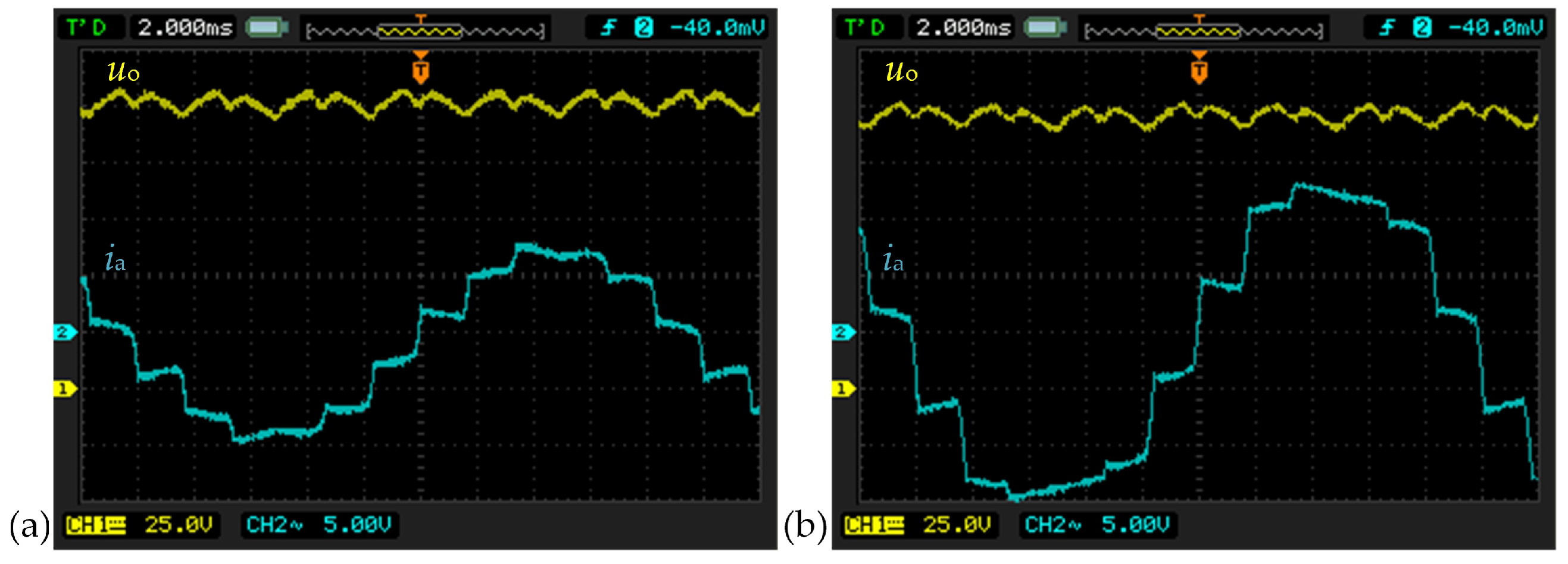
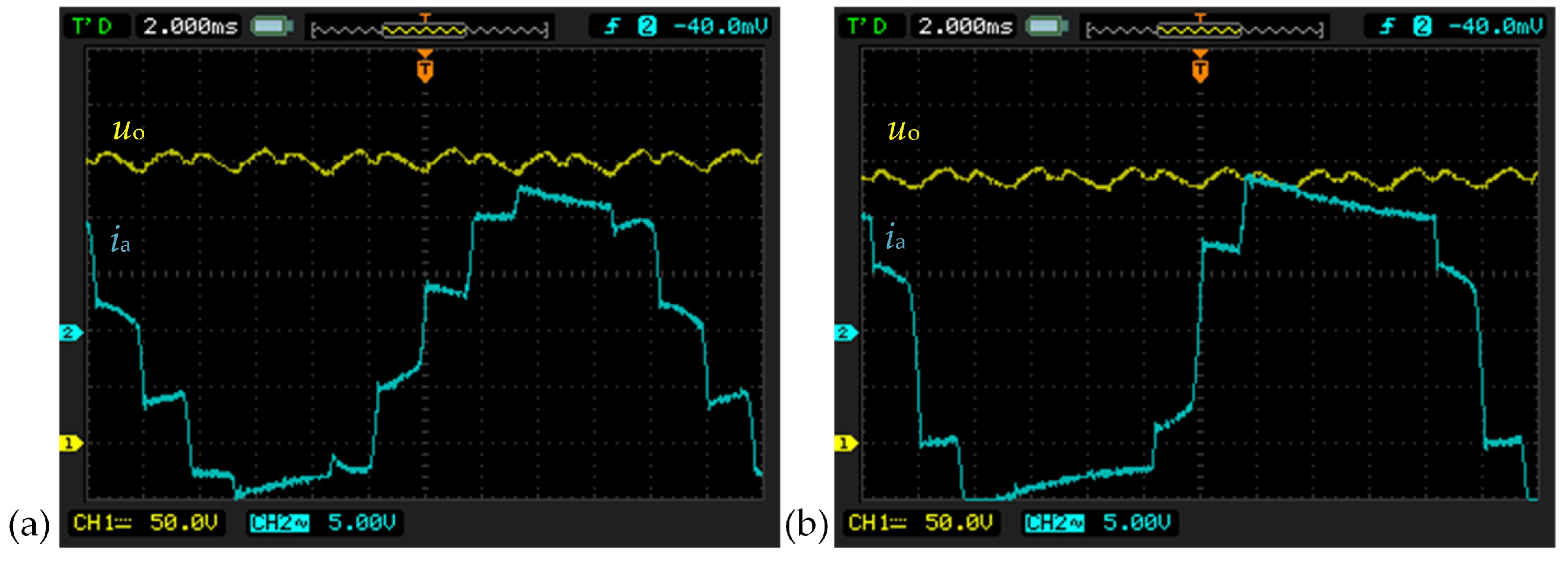
The laboratory setup of an uncontrolled 12-pulse rectifier based on the PSI system, with a power output of 15 kW, is shown in Figure 22. Experimental studies were performed according to the cases presented in Table 4. The Figure 23 and Figure 24 show the supply current i a and output voltage u o waveforms for particular resistive load and supply voltage values.
The findings reveal that the performance of the uncontrolled rectifier is contingent on the supply voltage and load, which exert an influence on the shape of the supply current. Nevertheless, the obtained waveforms are consistent with those achieved during the simulation test, which verifies the correctness of the model and the assumptions of the simulation studies.
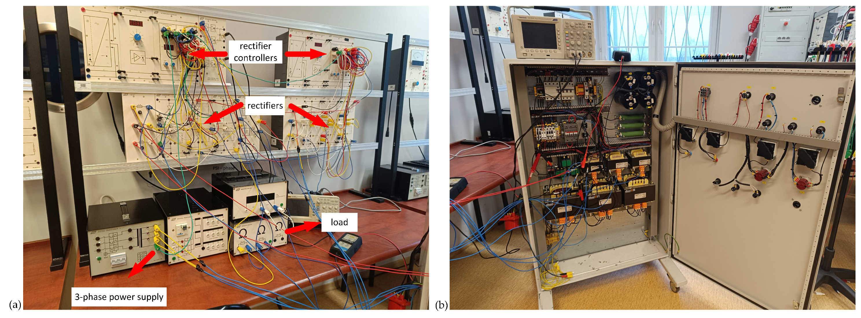
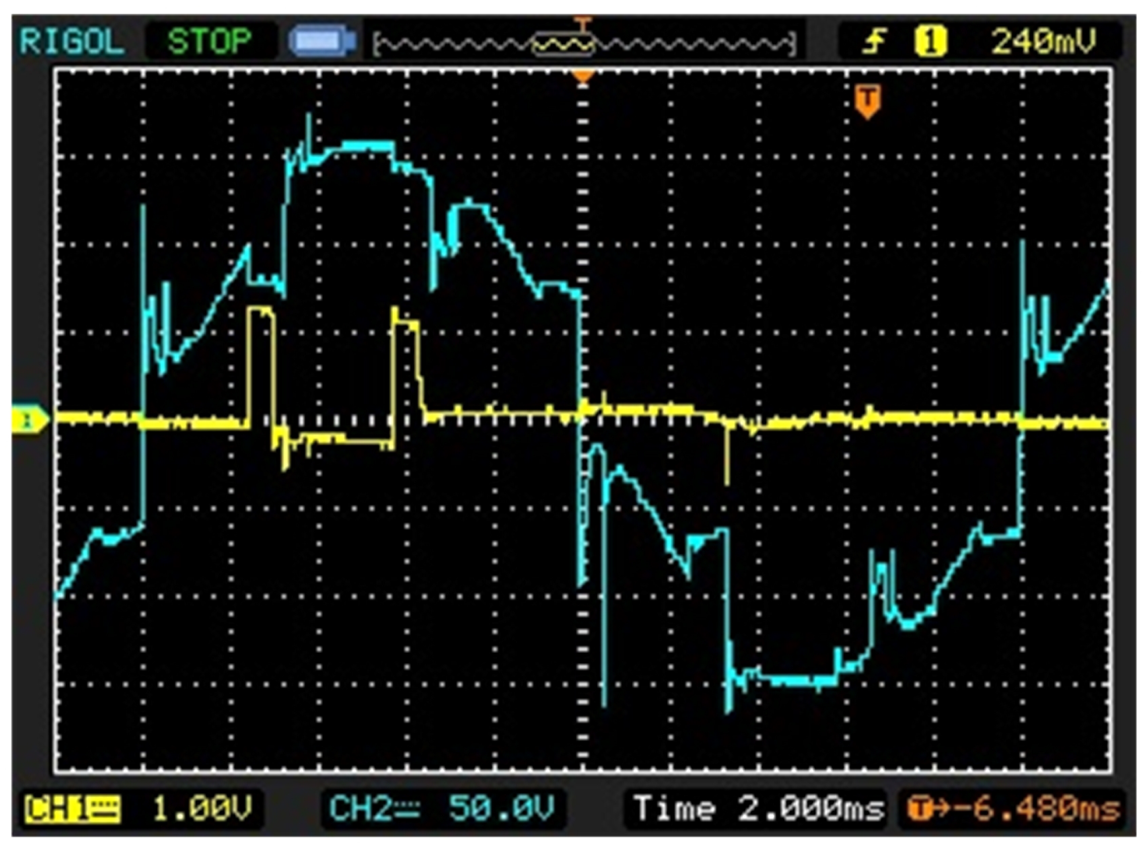
The Figure 25 illustrates the tested system of the controlled 12-pulse rectifier. The implementation of two controlled rectifier units was achieved through the utilisation of thyristors, which were triggered by a laboratory pulse-generation system. The initiation of the firing process was synchronised with the phase voltages of the six-phase system, which were obtained at the output of the PSI. As was mentioned in Section 3.2, the distorted voltage waveform can introduce difficulties in the determination of an accurate commutation point. A representative waveform of voltage before the rectifier bridge, along with the triggering signals, is illustrated in Figure 26.
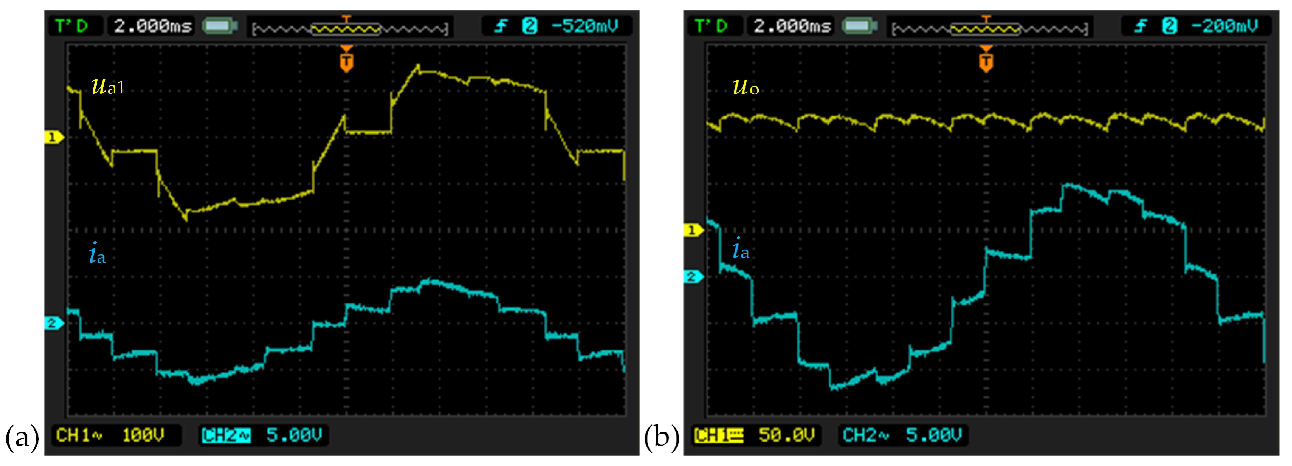
The system was commissioned from a laboratory transformer at a reduced voltage level in order to ensure safe operation and to verify correct functionality under low-voltage conditions. It is imperative to establish an appropriate load to ensure the effective functioning of both uncontrolled and controlled rectifier configurations. As in the previously presented simulation studies, no output filter (capacitive or inductive) was used; the load was connected directly to the rectifier output. The thyristor firing angle was the same as in the simulation tests (see Section 3.2) and equal to: α = 40 . The achieved waveforms are presented in Figure 27 and are consistent with those observed in the simulation tests.
The main experimental findings are as follows:
  • The validity of the simulation models is confirmed by the obtained waveforms.
  • The rectifier operation is contingent upon the load conditions.
  • Controlled rectifiers introduce additional waveform distortion due to the firing angle.
  • The experimental results validate the theoretical assumptions regarding phase-shifting inductors.
Considering the fact that waveforms obtained in experimental tests are consistent with those from simulation studies, both for controlled and uncontrolled 12-pulse rectifiers, some conclusions can be derived. The experiment has provided a robust validation of the model and the assumptions employed in the simulation studies. It is therefore reasonable to extrapolate the results to higher pulse numbers. The same phase-shifting principle based on winding ratios applies to all analysed topologies. Moreover, the general relationship h = n p ± 1 governs harmonic elimination independently of the specific topology. Consequently, the trends observed for the 12-pulse rectifier can be extrapolated to 18- and 24-pulse configurations.

4. Series Operation of Multi-Pulse Rectifiers Developed with Magnetically Coupled Inductors

The primary advantage of multi-pulse rectifiers employing magnetically coupled inductors, in which the rectifier bridges are connected in parallel, lies in their ability to deliver high DC currents at relatively low DC voltages. In certain applications, a principal objective of rectifier design is the generation of higher DC voltages. Such configurations are particularly advantageous in traction systems [2,32,33].
In contrast to parallel configurations (high current capability), a series connection aims at increasing output voltage. An increase in DC voltage can be achieved by connecting rectifier bridges in series, with each bridge supplied by a voltage that is phase-shifted by a specific angle relative to the preceding bridge. To investigate this possibility, the authors conducted both simulation and experimental studies. It should be noted that, to the best of the authors’ knowledge, similar implementations have not been reported in the existing literature.

4.1. Simulation Studies of Uncontrolled and Controlled 12-Pulse Rectifiers

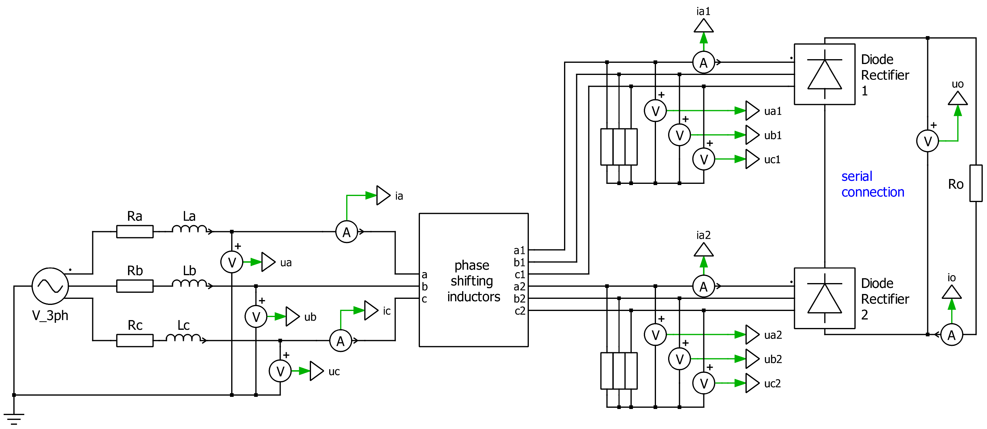
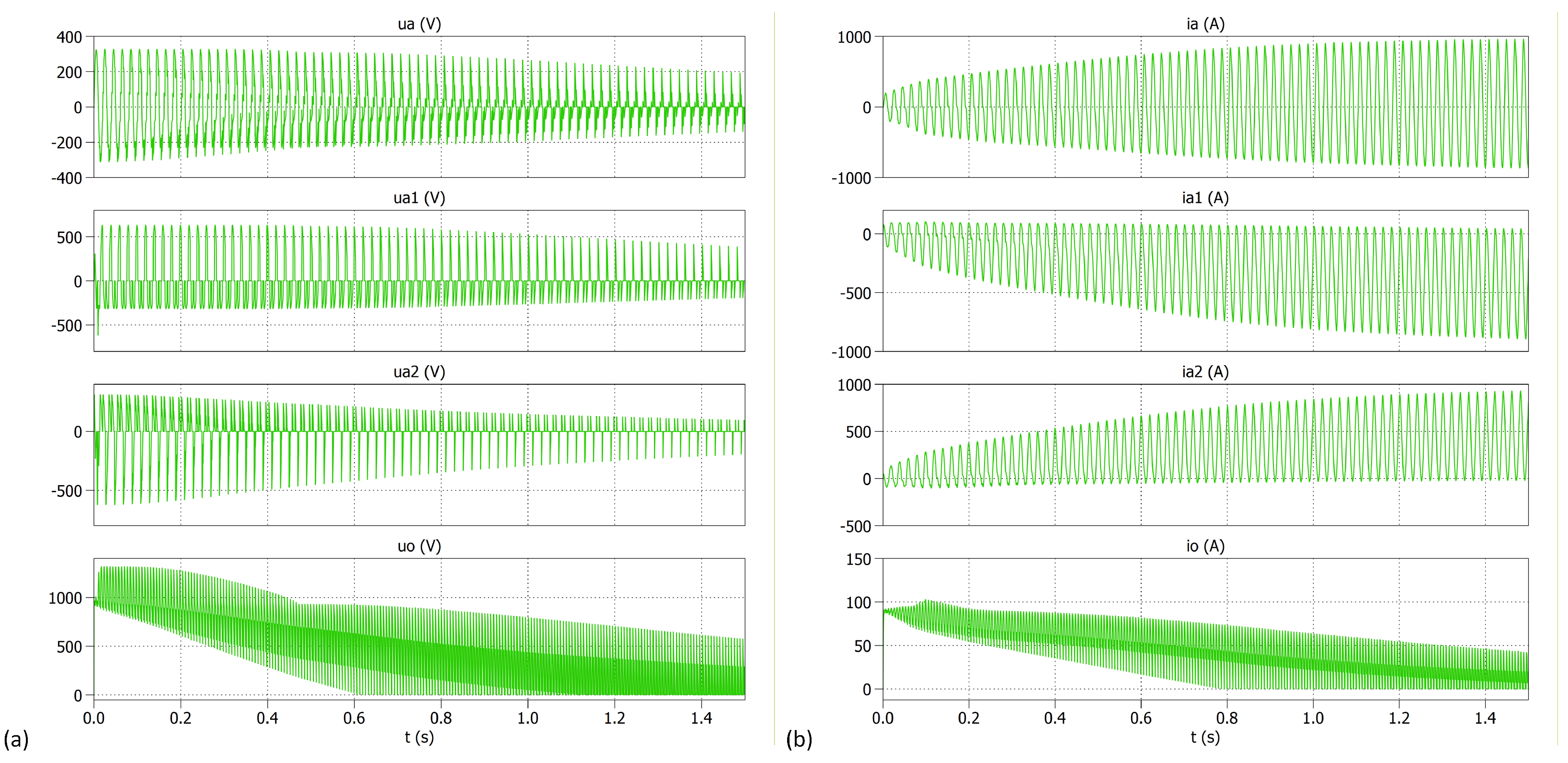
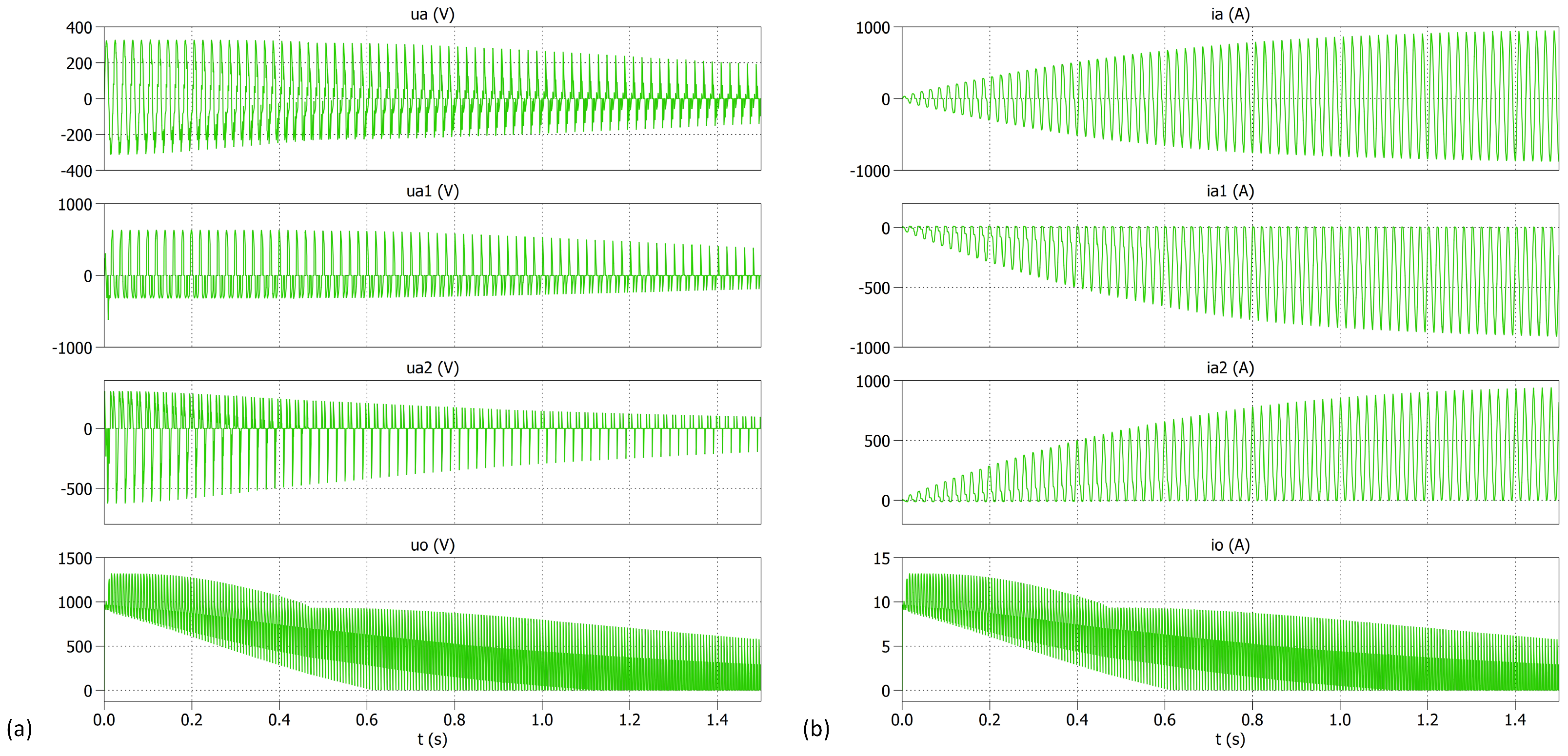
For the purposes of the simulation studies, the schematic presented in Figure 4 was modified to the configuration shown in Figure 28.
Simulation tests for the circuit shown in Figure 28 were performed for the same parameters and PLECS settings as in the previous cases outlined in Section 3.1. The achieved results are presented in Figure 29 and Figure 30.
The obtained results show that with series-connected rectifier bridges, there is a sharp increase in currents from the grid and currents between the inductors and rectifier bridges. The voltages, on the other hand, show a rapid drop in value and distortion. The simulation results differ from the previously obtained results for a 12-pulse rectifier operating with parallel-connected bridges. The current rise and voltage drop occur more rapidly at higher loads, which is consistent with expectations. Such a dynamic increase in currents and voltage drops is typical of a short-circuit condition, which in this case occurs through the inductors.

4.2. Experimental Studies of Uncontrolled and Controlled 12-Pulse Rectifiers

Owing to the inconclusive nature of the simulation results, experimental investigations were also conducted on both uncontrolled and controlled 12-pulse rectifiers. The laboratory setups corresponded to the configurations presented in the preceding figures (Figure 28). The obtained results can be summarised as follows: in both cases, switching on the power immediately resulted in a short circuit, activating the protective devices of the laboratory system.
This behaviour can be attributed to the lack of galvanic isolation in the magnetically coupled inductor system. Consequently, irrespective of the chosen rectifier firing angle, a short circuit occurs through the inductors.
While the lack of galvanic isolation suggests potential limitations, the actual behaviour of magnetically coupled inductors is not trivial and depends on magnetic coupling and circuit conditions. The results confirm that series operation leads to internal short-circuit paths, which constitute an important practical limitation of this topology. This phenomenon precludes the series connection of the rectifier bridges.
The role of series connection has been better motivated and explicitly compared with the parallel configuration, highlighting its practical limitations due to the lack of galvanic isolation.

5. Conclusions

Multi-pulse rectifiers are becoming more popular because of their advantageous properties. They are characterised, depending on the module configuration (series or parallel connection), by a higher output voltage or a higher current-carrying capacity. Furthermore, these converters have been shown to exhibit superior parameters in terms of electric power quality when compared to the conventional six-pulse converters that are more commonly employed. Such multi-pulse topologies can be based either on transformers or magnetically coupled inductors. In comparison with transformers that possess analogous properties, the latter exhibit reduced dimensions, diminished power ratings, and diminished financial expense. However, their utilisation in series-connected rectifier modules is precluded by their inability to provide galvanic separation, a key limitation that compromises their efficacy. This phenomenon has been verified both in simulation and experimental tests. The role of series connection has been better motivated and explicitly compared with the parallel configuration, highlighting its practical limitations due to the lack of galvanic isolation.
A study on parallel operation has revealed a correlation between the number of converter pulses and the THD coefficient value. It is evident that an increase in the number of rectifier pulses results in a decrease in both the T H D u and T H D i values. However, this decline becomes less pronounced as the number of pulses increases. Concurrently, the advancement and cost of the converter increase, signifying the necessity of conducting an economic evaluation of the utilisation of a specific topology of multi-pulse rectifier for each individual application.
The subsequent issue pertains to the selection of the controlled and uncontrolled versions of the converter. While the former provides DC voltage regulation, the latter is more straightforward and economical due to the absence of a control system. Furthermore, the regulation range decreases with increasing pulse number; therefore, uncontrolled multi-pulse rectifiers are preferable and widely used.
Moreover, the analysis of 12-, 18-, and 24-pulse rectifiers has shown that their proper operation strongly depends on the load value. Rectifiers constructed with magnetically coupled inductors require adequate loading; therefore, operation under no-load or light-load conditions is not recommended, as the current flowing through the inductors becomes too low to ensure sufficient magnetic coupling. As a result, the required phase shifts between the output terminals cannot be achieved, which is essential for the correct operation of these rectifiers. Operation under distorted supply voltage conditions can also be problematic. Higher-order harmonics present in distorted supply voltages alter the magnetic conditions within the inductor circuit, thereby affecting the coupling, which should depend solely on the number of turns.

Author Contributions

Conceptualisation, A.M.; methodology, A.M. and A.B.; formal analysis, A.M., A.B. and K.K.; investigation, A.M. and A.B.; writing—original draft preparation, A.M., A.B. and K.K.; supervision, A.M. All authors have read and agreed to the published version of the manuscript.

Funding

This research received no external funding.

Data Availability Statement

The original contributions presented in this study are included in the article. Further inquiries can be directed to the corresponding author.

Conflicts of Interest

The authors declare no conflicts of interest.

References

  1. Singh, B.; Gairola, S.; Singh, B.N.; Chandra, A.; Al-Haddad, K. Multipulse AC–DC Converters for Improving Power Quality: A Review. IEEE Trans. Power Electron. 2008, 23, 260–281. [Google Scholar] [CrossRef]
  2. Zaninelli, D.; Jafari Kaleybar, H.; Brenna, M. Modeling and Evaluation of Reversible Traction Substations in DC Railway Systems: A Real-Time Simulation Platform Toward a Digital Twin. Appl. Sci. 2026, 16, 80. [Google Scholar] [CrossRef]
  3. Arvindan, A.N.; Ashwin, R.; Murthi, M.K. Multipulse Diode Rectifiers: Power Quality Perspective Based on Experimental Data. In Proceedings of the IEEE International Conference on Intelligent Circuits and Systems (IICPE), Jaipur, India, 13–15 December 2018. [Google Scholar] [CrossRef]
  4. Kumar, K.S.; Sukesh, C.H.; Anoop, K.J.; Kanchana, K. A Review on Power Quality Improvement Using AC to DC Converters. In 2017 IEEE International Conference on Power, Control, Signals and Instrumentation Engineering (ICPCSI); IEEE: New York, NY, USA, 2017; Volume 56, pp. 2968–2974. [Google Scholar] [CrossRef]
  5. Mu, X.; Chen, X.; Liu, Q.; Wang, Y.; Bai, T.; Ge, L.; Ma, X. A Novel Shunt Zigzag Double-Tap Low-Harmonic Multi-Pulse Rectifier Based on a Three-Stage Power Electronic Phase-Shifting Transformer. Sensors 2024, 24, 5564. [Google Scholar] [CrossRef] [PubMed]
  6. Strzelecki, R.; Mysiak, P. A hybrid, coupled reactors based 18-pulse diode rectifier with active power filter. In Proceedings of the 2014 IEEE International Conference on Intelligent Energy and Power Systems (IEPS), Kyiv, Ukraine, 2–6 June 2014; pp. 94–101. [Google Scholar] [CrossRef]
  7. Strzelecki, R.; Sak, T.; Zolov, P.D.; Moradewicz, A.; Grabarek, M. Multi-pulse VSC arrangements with coupled reactors. In Proceedings of the 2016 IEEE 2nd Annual Southern Power Electronics Conference (SPEC), Auckland, New Zealand, 5–8 December 2016; pp. 1–6. [Google Scholar] [CrossRef]
  8. Strzelecki, R.; Sak, T.; Grabarek, M.; Zolov, P.; Strzelecka, N. Low harmonic multipulse voltage converters using coupled reactors. In Proceedings of the 2016 15th Biennial Baltic Electronics Conference (BEC), Tallinn, Estonia, 3–5 October 2016; pp. 195–198. [Google Scholar] [CrossRef]
  9. Mysiak, P.; Sleszynski, W.; Cichowski, A. Experimental test results of the 150kVA 18-pulse diode rectifier with series active power filter. In Proceedings of the 2016 10th International Conference on Compatibility, Power Electronics and Power Engineering (CPE-POWERENG), Bydgoszcz, Poland, 29 June–1 July 2016; pp. 380–383. [Google Scholar] [CrossRef]
  10. Singh, B.; Bhuvaneswari, G.; Garg, V. Harmonic mitigation using 12-pulse AC-DC converter in vector-controlled induction motor drives. IEEE Trans. Power Deliv. 2006, 21, 1483–1492. [Google Scholar] [CrossRef]
  11. Saini, H.; Sandeep, N.; P, S.P. 24-Pulse Boosting Rectifier for Aviation Application. IEEE J. Emerg. Sel. Top. Ind. Electron. 2025, 6, 768–776. [Google Scholar] [CrossRef]
  12. Kulkarni, R.D.; Srivastava, G.D.; Rautela, P. Design Implementation and Parallel Operation of High-Current High-Power Multipulse Converters Feeding Nuclear Fuel Simulators. IEEE Trans. Ind. Appl. 2021, 57, 1598–1608. [Google Scholar] [CrossRef]
  13. Ma, D.; Liu, S.; Jin, Y.; Li, Y.; Wu, C. Research on a Multi-pulse Diode Rectification in Space Nuclear Power System. In Proceedings of the 2019 IEEE 4th Advanced Information Technology, Electronic and Automation Control Conference (IAEAC), Chengdu, China, 20–22 December 2019; pp. 2051–2055. [Google Scholar] [CrossRef]
  14. Abdollahi, R.; Salemnia, A.; Mosallanejad, A.; Gharehpetian, G. EV charging stations multipulse rectifiers based on passive harmonic reduction circuits: A critical survey. Renew. Sustain. Energy Rev. 2025, 215, 115499. [Google Scholar] [CrossRef]
  15. Patel, H.; Shah, M. Performance Analysis of Multi-Pulse Rectifiers for Power Quality Enhancement. In Proceedings of the IEEE International Conference on Power Electronics, Drives and Energy Systems (PEDES 2022), Jaipur, India, 14–17 December 2022. [Google Scholar]
  16. Abdollahi, R.; Gharehpetian, G.B.; Mohammadi, F.; Prakash P, S. Multi-Pulse Rectifier Based on an Optimal Pulse Doubling Technique. Energies 2022, 15, 5567. [Google Scholar] [CrossRef]
  17. Nahin, N.I.; Nafis, M.M.; Biswas, S.P.; Hosain, M.K.; Das, P.; Haq, S. Investigating the Input Power Quality of Multi-Pulse AC–DC Power Converter Fed Induction Motor Drives. Heliyon 2022, 8, e11733. [Google Scholar] [CrossRef] [PubMed]
  18. Szwarc, K.J.; Cichowski, A.; Szczepankowski, P.; Nieznański, J.; Strzelecki, R. Multilevel voltage source inverter with coupled reactors using coarsely quantized pulse amplitude modulation. Bull. Pol. Acad. Sci. Tech. Sci. 2025, 73, 153227. [Google Scholar] [CrossRef]
  19. Baiceanu, F.C.; Munteanu, F.; Nemes, C. Influence of Multi-Pulse Rectifier on Power Quality in an Industrial Environment. In Proceedings of the 2019 8th International Conference on Modern Power Systems (MPS), Cluj Napoca, Romania, 21–23 May 2019; pp. 1–6. [Google Scholar] [CrossRef]
  20. Voitovych, Y.; Makarov, V.; Pichkalov, I. 18-pulse Rectifier with Electronic Phase Shifting with Autotransformer in Inverter and Rectifier Mode. In Proceedings of the 2018 IEEE 6th Workshop on Advances in Information, Electronic and Electrical Engineering (AIEEE), Vilnius, Lithuania, 8–10 November 2018; pp. 1–5. [Google Scholar] [CrossRef]
  21. Calar, M.; Durna, E.; Kayisli, K. 3-Phase Multi-Pulse Rectifiers with Different Phase Shifting Transformers and Comparison of Total Harmonic Distortion. In Proceedings of the 2022 9th International Conference on Electrical and Electronics Engineering (ICEEE), Alanya, Turkey, 29–31 March 2022; pp. 60–64. [Google Scholar] [CrossRef]
  22. Su, G.; Li, Y.; Liu, S.; Wang, X. Optimized Design for the 12-Pulse Uncontrolled Rectifier With a Coupling Interphase Reactor. In Proceedings of the 2020 IEEE International Conference on Information Technology, Big Data and Artificial Intelligence (ICIBA), Chongqing, China, 6–8 November 2020; Volume 1, pp. 1300–1304. [Google Scholar] [CrossRef]
  23. Lambert, G.; Costabeber, A.; Wheeler, P.; De Novaes, Y.R. A Unidirectional Insulated AC–DC Converter Based on the Hexverter and Multipulse-Rectifier. IEEE Trans. Power Electron. 2020, 35, 2363–2371. [Google Scholar] [CrossRef]
  24. Meng, F.; Du, Q.; Wang, L.; Gao, L.; Man, Z. A Series-Connected 24-Pulse Rectifier Using Passive Voltage Harmonic Injection Method at DC-Link. IEEE Trans. Power Electron. 2019, 34, 8503–8512. [Google Scholar] [CrossRef]
  25. Chivite-Zabalza, F.; Forsyth, A.; Trainer, D. A Simple, Passive 24-Pulse AC–DC Converter With Inherent Load Balancing. IEEE Trans. Power Electron. 2006, 21, 430–439. [Google Scholar] [CrossRef]
  26. Szwarc, K.J.; Szczepankowski, P.; Nieznański, J.; Swinarski, C.; Usoltsev, A.; Strzelecki, R. Hybrid Modulation for Modular Voltage Source Inverters with Coupled Reactors. Energies 2020, 13, 4450. [Google Scholar] [CrossRef]
  27. Mysiak, P.; Strzelecki, R.; Klytta, M. 36-pulse rectifier with a system of coupled three-phase reactors. In Proceedings of the 2013 International Conference-Workshop Compatibility And Power Electronics, Ljubljana, Slovenia, 5–7 June 2013; pp. 75–79. [Google Scholar] [CrossRef]
  28. Mysiak, P. A multi-pulse diode rectifier with a coupled three-phase reactor - the design method. In Proceedings of the IEEE Compatibility in Power Electronics, Gdynia, Poland, 1–3 June 2005; pp. 259–264. [Google Scholar] [CrossRef]
  29. Depenbrock, M.; Niermann, C. A New 12-Pulse Rectifier Circuit with Line-Side Interphase Transformer and Nearly Sinusoidal Line Current. In Proceedings of the 6th Conference on Power Electronics and Motion Control (PEMC), Budapest, Hungary, 1–3 October 1990; Volume 2, pp. 374–378. [Google Scholar]
  30. PN-EN 61558-2-20:2022-12; Safety of Transformers, Reactors, and Inductors—Part 2-20: Particular Requirements and Tests for Isolating Transformers and Power Supply Units Incorporating Isolating Transformers. Polish Committee for Standardization: Warsaw, Poland, 2022.
  31. IEEE Standard 519-2014; IEEE Recommended Practice and Requirements for Harmonic Control in Electric Power Systems. IEEE: New York, NY, USA, 2014.
  32. Bałkowiec, T.; Koczara, W. Three-Phase Rectifier Dedicated to DC Traction Substation. PrzegląD Elektrotechniczny 2017, 9, 41–45. [Google Scholar] [CrossRef]
  33. Vilberger, M.; Arestova, A.; Matrenin, P.; Domakhin, E. Analysis of rectification techniques and autonomous hybrid power plants potential for railway power supply systems. Energy Rep. 2022, 8, 957–966. [Google Scholar] [CrossRef]
Figure 1. The configuration of PSI that enables the conversion of a 3-phase voltage system into a 6-phase system. (a) Detailed PSI’s connection diagram. (b) Equivalent PSI block used in models presented in the paper.
Energies 19 02333 g001
Figure 2. The configuration of CM that enables the conversion of a 3-phase voltage system into a 6-phase system. (a) Detailed CM’s connection diagram; (b) equivalent CM block used in models presented in the paper.
Energies 19 02333 g002
Figure 3. PSI: (a) phase shifting inductors used in the experimental studies; (b) parameters placed on name plate.
Energies 19 02333 g003
Figure 4. Schematic diagram of the uncontrolled 12-pulse rectifier based on PSI and two parallel-connected 6-pulse rectifier bridges.
Energies 19 02333 g004
Figure 5. Schematic diagram of the uncontrolled 12-pulse rectifier based on PSI and two parallel-connected 6-pulse bridge rectifiers, which was used for simulation tests (case C2).
Energies 19 02333 g005
Figure 6. Selected voltages and currents waveforms of the uncontrolled 12-pulse rectifier. (a) Voltage waveforms: u a —supply phase voltage; u a 1 , u a 2 —phases voltages before the rectifier bridges; and u o —load voltage. (b) Current waveforms: i a —supply current; i a 1 , i a 2 —phases currents between PSI and the rectifier bridges; and i o —load current.
Energies 19 02333 g006
Figure 7. Frequency spectra of selected voltages of the uncontrolled 12-pulse rectifier: (a)—voltage spectra for a load of R o = 100 Ω ; (b)—voltage spectra for a load of R o = 10 Ω .
Energies 19 02333 g007
Figure 8. Frequency spectra of selected currents of the uncontrolled 12-pulse rectifier: (a)—current spectra for a load of R o = 100 Ω ; (b)—current spectra for a load of R o = 10 Ω .
Energies 19 02333 g008
Figure 9. Schematic diagram of the controlled 12-pulse rectifier based on PSI and two parallel-connected 6-pulse bridge rectifiers, which was used for simulation tests (case C3).
Energies 19 02333 g009
Figure 10. Selected voltages and currents waveforms of the controlled 12-pulse rectifier. (a) Voltage waveforms: u a —supply phase voltage; u a 1 , u a 2 —phases voltages before the rectifier bridges; and u o —load voltage. (b) Current waveforms: i a —supply current; i a 1 , i a 2 —phases currents between PSI and the rectifier bridges; and i o —load current.
Energies 19 02333 g010
Figure 11. Frequency spectra of selected voltages of the controlled 12-pulse rectifier: (a)—voltage spectra for a load of R o = 100 Ω ; (b)—voltage spectra for a load of R o = 10 Ω .
Energies 19 02333 g011
Figure 12. Frequency spectra of selected currents of the controlled 12-pulse rectifier: (a)—current spectra for a load of R o = 100 Ω ; (b)—current spectra for a load of R o = 10 Ω .
Energies 19 02333 g012
Figure 13. Schematic diagram of the controlled 18-pulse rectifier based on CM, PSI, and three parallel-connected 6-pulse bridge rectifiers, which was used for simulation tests (case C4).
Energies 19 02333 g013
Figure 14. Selected voltages and currents waveforms of the uncontrolled 18-pulse rectifier. (a) Voltage waveforms: u a —supply phase voltage; u a 1 , u a 2 —phases voltages before the rectifier bridges; and u o —load voltage. (b) Current waveforms: i a —supply current; i a 1 , i a 2 —phases currents between PSI and the rectifier bridges; and i o —load current.
Energies 19 02333 g014
Figure 15. Frequency spectra of selected voltages of the uncontrolled 18-pulse rectifier: (a)—voltage spectra for a load of R o = 100 Ω ; (b)—voltage spectra for a load of R o = 10 Ω .
Energies 19 02333 g015
Figure 16. Frequency spectra of selected currents of the uncontrolled 18-pulse rectifier: (a)—current spectra for a load of R o = 100 Ω ; (b)—current spectra for a load of R o = 10 Ω .
Energies 19 02333 g016
Figure 17. Schematic diagram of the uncontrolled 24-pulse rectifier based on PSI and four parallel-connected 6-pulse bridge rectifiers, which was used for simulation tests (case C5).
Energies 19 02333 g017
Figure 18. Selected voltages and currents waveforms of the uncontrolled 24-pulse rectifier. (a) Voltage waveforms: u a —supply phase voltage; u a 1 , u a 3 —phases voltages before the rectifier bridges; and u o —load voltage. (b) Current waveforms: i a —supply current; i a 1 , i a 3 —phases currents between PSI and the rectifier bridges; and i o —load current.
Energies 19 02333 g018
Figure 19. Frequency spectra of selected voltages of the uncontrolled 24-pulse rectifier: (a)—voltage spectra for a load of R o = 100 Ω ; (b)—voltage spectra for a load of R o = 10 Ω .
Energies 19 02333 g019
Figure 20. Frequency spectra of selected currents of the uncontrolled 24-pulse rectifier: (a)—current spectra for a load of R o = 100 Ω ; (b)—current spectra for a load of R o = 10 Ω .
Energies 19 02333 g020
Figure 21. Current vectors of particular rectifier topologies: (a) 12-pulse; (b) 18-pulse; and (c) 24-pulse.
Energies 19 02333 g021
Figure 22. The laboratory setup of an uncontrolled 12-pulse rectifier based on the PSI system.
Energies 19 02333 g022
Figure 23. Case E1. The waveform of the output voltage u o and the supply current i a obtained for the phase-to-phase supply voltage of 110 V and: (a) R o = 33.3 Ω ; (b) R o = 16.7 Ω .
Energies 19 02333 g023
Figure 24. Case E2. The waveform of the output voltage u o and the supply current i a obtained for the phase-to-phase supply voltage of 220 V and: (a) R o = 33.3 Ω ; (b) R o = 16.7 Ω .
Energies 19 02333 g024
Figure 25. View of the laboratory stand: (a) thyristor bridges with control circuit; (b) phase-shifting inductors with electrical apparatuses.
Energies 19 02333 g025
Figure 26. Case E3. The waveforms of voltage used to synchronize the thyristor firing pulses (blue) and exemplary pulses of one thyristor (yellow).
Energies 19 02333 g026
Figure 27. Case E3. The waveforms of: (a) the voltage u a 1 before the rectifying bridge and the supply current i a ; (b) load voltage u o and the supply current i a .
Energies 19 02333 g027
Figure 28. Schematic diagram of the uncontrolled 12-pulse rectifier based on PSI and two serial-connected 6-pulse bridge rectifiers, which was used for simulation tests.
Energies 19 02333 g028
Figure 29. Waveforms of selected voltages and currents measured during the series operation of the 12-pulse rectifier: (a,b)—waveforms of voltages and currents for a resistance of R o = 10 Ω .
Energies 19 02333 g029
Figure 30. Waveforms of selected voltages and currents measured during the series operation of the 12-pulse rectifier: (a,b)—waveforms of voltages and currents for a resistance of R o = 100 Ω .
Energies 19 02333 g030
Table 1. Inductances of particular PSI systems measured with RLC bridge at the frequency equal to 50 Hz.
PSI 1PSI 2PSI 3
L, mHL, mHL, mH
N x = 29 4.44.24.2
N y = 79 31.830.730.4
N z = 108 39.337.136.6
Table 2. Simulation cases.
CaseTopologyControl R a , R b , R c L a , L b , L c R o Remark
C16-pulseuncontrolled 0.001 Ω 1.1 mH10 Ω /100 Ω reference
C212-pulseuncontrolled 0.001 Ω 1.1 mH10 Ω /100 Ω baseline
C312-pulsecontrolled ( α = 40 ) 0.001 Ω 1.1 mH10 Ω /100 Ω control effect
C418-pulseuncontrolled0.001 Ω 1.1 mH10 Ω /100 Ω higher pulse
C524-pulsecontrolled0.001 Ω 1.1 mH10 Ω /100 Ω highest pulse
Table 4. Experiment cases.
CaseTopologyControlSupply Voltage U phase-to-phase R o
E112-pulseuncontrolled110 V33.3 Ω /16.7 Ω
E212-pulseuncontrolled220 V33.3 Ω /16.7 Ω
E312-pulsecontrolled ( α = 40 ) 110 V25 Ω
Disclaimer/Publisher’s Note: The statements, opinions and data contained in all publications are solely those of the individual author(s) and contributor(s) and not of MDPI and/or the editor(s). MDPI and/or the editor(s) disclaim responsibility for any injury to people or property resulting from any ideas, methods, instructions or products referred to in the content.