1. Introduction
Submarine cable is the lifeline for offshore power transmission, and it plays a pivotal role in achieving long distance, high capacity electricity delivery [
1,
2,
3,
4]. With the accelerated global energy transition in recent years, the continuous expansion of offshore wind farm scales has placed higher demands on the transmission capacity and operational reliability of submarine cable [
5,
6,
7,
8]. However, existing submarine cables are typically laid in installation scenarios with different heat dissipation conditions. In the event that heat dissipation conditions worsen in a particular installation scenario, the conductor temperature within that scenario will increase substantially. The installation scenarios with poor heat dissipation conditions will become the thermal bottleneck of the entire submarine cable line [
9,
10]. The entire transmission capacity of the submarine cable line will be significantly constrained by such a thermal bottleneck, which leads to a decrease in grid asset utilization. Therefore, a precise evaluation of submarine cable ampacity is essential in laying scenarios with poor heat dissipation. By clearly identifying the constraints imposed by the thermal bottleneck on the transmission capacity of the submarine cable, efficient cooling methods can be devised to enhance the overall transmission capacity of the submarine cable line.
The landing section of the submarine cable often needs to traverse complex terrain with substantial topographic variations. Thus, the directional drilling duct laying method has become a prevalent approach for the landing section of the submarine cable due to its environmental friendliness and engineering convenience [
11,
12]. However, in the scenario of drilling duct laying, the cable duct is typically filled with slow air flow that has low thermal conductivity. This leads to a high thermal resistance between the cable conductor and the duct wall. Moreover, an increase in the burial depth may increase the environmental thermal resistance around the cable duct [
13,
14,
15]. Ultimately, the conductor temperature of the submarine cable laid in a directional drilling duct laying scenario experiences a significant increase relative to the environmental boundary. This may lead to an overheating problem, causing the cable section laid in the directional drilling duct to become a thermal bottleneck point along the entire submarine cable line. Therefore, it is essential to conduct thermal evaluation investigations specifically on the submarine cable laid in the directional drilling duct.
Currently, to accurately obtain the temperature distribution on the submarine cable, Zhang Y et al. [
16] established an electro-thermal-fluid coupled multi-physics model for the submarine cable in pipeline installations, enabling the evaluation of cable current-carrying capacity under various laying scenarios. Ramirez L et al. [
17] proposed an analytical model based on the IEC 60287 method for calculating the temperature rise of the cable in pipes. They utilized the method of mirror symmetry to determine the equivalent thermal resistance of the external environment around the cable pipe, achieving rapid inversion of the conductor temperature for pipe-laid cables. Lin R et al. [
18] developed a simulation model for calculating the current-carrying capacity of the submarine cable under full installation conditions, allowing for the assessment of the current-carrying capacity in directional drilling sections. However, existing investigations have not taken into account the changes in environmental heat dissipation conditions caused by the variable submarine cable burial depth in the directional drilling duct laying scenario. Furthermore, the submarine cable installed in directional drilling pipeline may be buried at significant depth, and the influence of deep ground temperature on the thermal behavior of deeply buried submarine cable was also not considered. Consequently, applying existing methods to conduct thermal evaluation for the submarine cable installed in a directional drilling pipeline would result in substantial errors. Therefore, it is necessary to investigate the influence of variable cable burial depth and deep soil temperature on the temperature distribution of the submarine cable laid in the directional drilling section. This will enable a more precise thermal evaluation of the cable, thereby achieving accurate control over the transmission capacity of the entire submarine cable line and identifying the requirements for enhancing the transmission capacity to design an effective cooling method.
Furthermore, to address overheating issues in directional drilling duct cable laying scenarios, Czapp S et al. [
19] proposed replacing the low-flow air within the pipeline with high thermal conductivity materials for the pipe-laid cable. This approach effectively improved the heat dissipation environment inside the pipeline, achieving a breakthrough in the current-carrying capacity of the cable in directional drilling sections installed via pipelines. Gao Z et al. [
20] employed a combined thermal enhancement strategy utilizing heat pipes and high thermal conductivity materials, successfully resolving overheating problems in trenchless cable installation scenarios within urban underground passages. However, the aforementioned investigations were conducted based on the installation conditions of land cable. The designed heat dissipation strategy lacks applicability in the directional drilling duct laying scenario of the submarine cable. Firstly, the cooling methods designed in these investigations rely on filling the cable passage with high thermal conductivity materials. In the directional drilling duct laying scenario of the submarine cable, the cable duct lacks the necessary sealing conditions. Filling the cable duct with such materials would require costly challenging sealing measures. Additionally, seawater surrounding the submarine cable would continuously infiltrate the cable duct after implementing sealing measures. The performance of high thermal conductivity materials would be influenced, and the effectiveness of the cooling method would be affected. Nevertheless, Zhang L et al. [
21] introduced the concept of creating new heat transfer pathways for the cable to develop novel cooling methods. Following this concept, it is also possible to design new ampacity improvement methods by establishing novel heat transfer pathways for submarine cables. In directional drilling duct laying scenarios of the submarine cable, low-temperature seawater can serve as a natural heat transfer medium. Therefore, a water circulation system based on seawater can be designed to establish new heat transfer pathways for the submarine cable. This would ultimately form a novel, engineering-feasible cooling method for directional drilling duct laying submarine cables, thereby enhancing the transmission capacity of the entire submarine cable line.
To address the limitations of existing IEC 60287 methods, this paper proposes an improved thermal rating method for submarine cable installed in a directional drilling pipeline on the basis of the IEC 60287 methods, which can explicitly account for the axial heat transfer and deep-soil temperature effects. This method enables accurate prediction of temperature distribution along the directional drilling pipeline and facilitates the development of targeted capacity-boosting measures tailored to the unique thermal environment of these sections.
Section 2 establishes the distributed-parameter electrical model for the long-distance submarine cable to determine conductor current distribution and analyzes the load transmission characteristics along the route, thereby identifying the potential overheating zones.
Section 3 develops the three-dimensional finite element model of the three-core submarine cable in the directional drilling pipeline to accurately assess transmission capacity and hotspot distribution under realistic thermal conditions.
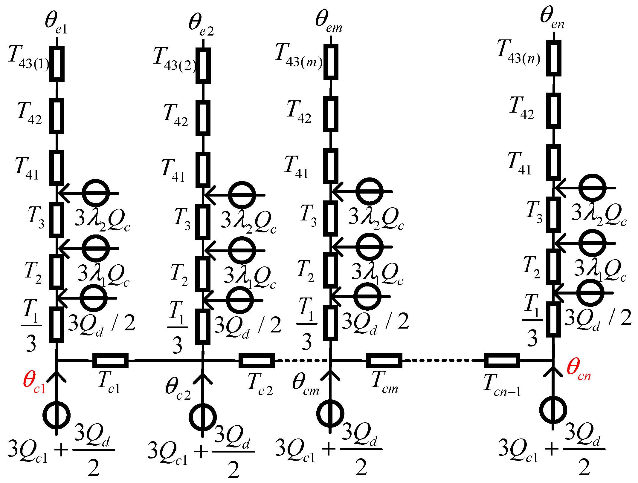
Section 4 constructs radial thermal circuit models for each sub-section of the directional drilling pipeline. Building on this, a quasi-3D thermal model for the inclined entry segment is formulated by incorporating axial heat conduction and deep-soil temperature effects.
Section 5 presents an improved thermal rating method based on the quasi-3D model, with its accuracy validated against high-fidelity simulations.
Section 6 proposes a water circulation cooling system specifically designed for the submarine cable installed in the directional drilling pipeline. The system can effectively enhance transmission capacity, and simulation-based results demonstrate its engineering feasibility and practical value in mitigating overheating in the directional drilling pipeline.
2. Analysis of Heat Generation of Directional Drilling Section of the Submarine Cable
The overheating issue observed in the horizontal directional drilling section arises from the combined effect of reduced heat dissipation and increased heat generation. Thus, before studying the overheating problem of the directional drilling section of the submarine cable, it is necessary to first determine the heat generation characteristics of this submarine cable section. For long-distance submarine cable, the influence of capacitive charging current cannot be ignored, which leads to an uneven current distribution along the submarine cable [
6]. As a result, identifying the thermal bottleneck of the submarine cable line requires considering not only the differences in heat dissipation across various laying sections but also the variations in heat generation due to non-uniform current distribution along the conductor. Thus, before studying the overheating problem of the directional drilling section of the submarine cable, it is necessary to first determine the heat generation characteristics of this submarine cable section. For this purpose, the long-distance submarine cable can be divided into
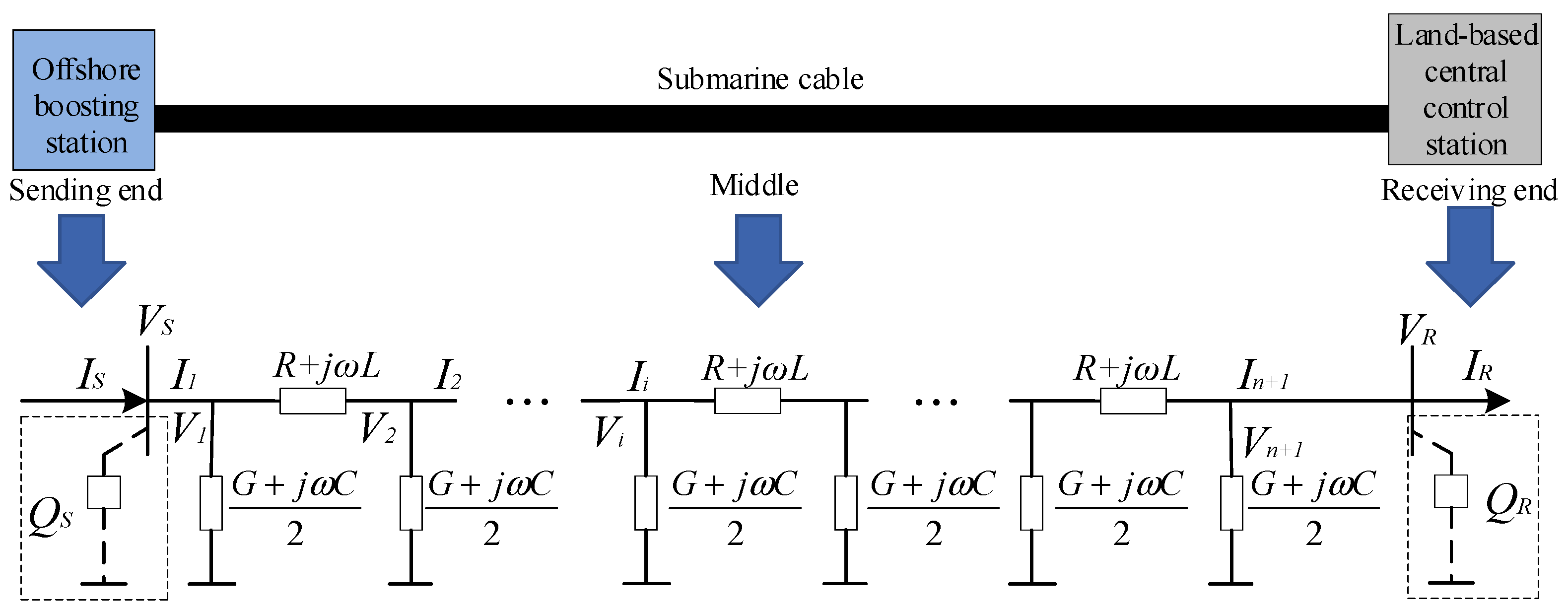
n equal-length segments, and each segment can be represented by a PI-type equivalent circuit. Then, the distributed parameter circuit model of the long-distance submarine cable can be used to estimate the distribution of currents along the submarine cable under different reactive power compensation scenarios, as shown in
Figure 1 [
6].
In
Figure 1,
R,
L,
G and
C are the resistance, inductance, conductance and capacitance of the unit length submarine cable, respectively.
QS and
QR are the reactive power capacities at the sending end and receiving end, respectively.
VS and
VR are the bus voltage at the sending end and receiving end, respectively.
IS and
IR are the input current at the sending end and the output current at the receiving end, respectively. The voltage and current at the connection nodes of each PI type equivalent circuit segment are denoted as
Vi and
Ii (
i = 1, 2…
n + 1), respectively. The solution method of the distributed parameter circuit model of the long-distance submarine cable presented in [
6] was still adopted in this paper, and the node current
Ii can be obtained by the following equations:
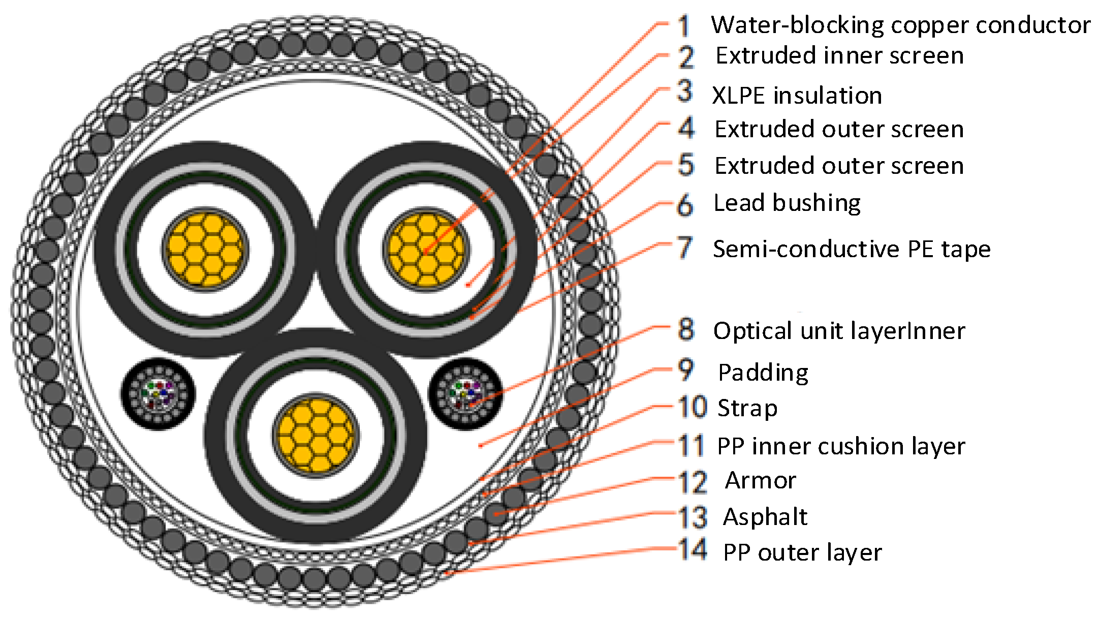
In engineering, the strategy of applying reactive power compensation at the sending end is frequently employed to tackle the voltage rise phenomenon at the receiving end of the submarine cable line. For instance, a 220 kV 3 × 1000 mm
2 submarine cable with a length of 50 km used for the power transmission of a 300 MW wind farm was taken as an example. The cross-section of selected submarine cable is presented in
Figure 2, and the detailed structural parameters are shown in
Table 1. The current distribution situations along the submarine cable under various reactive power compensation schemes were investigated.
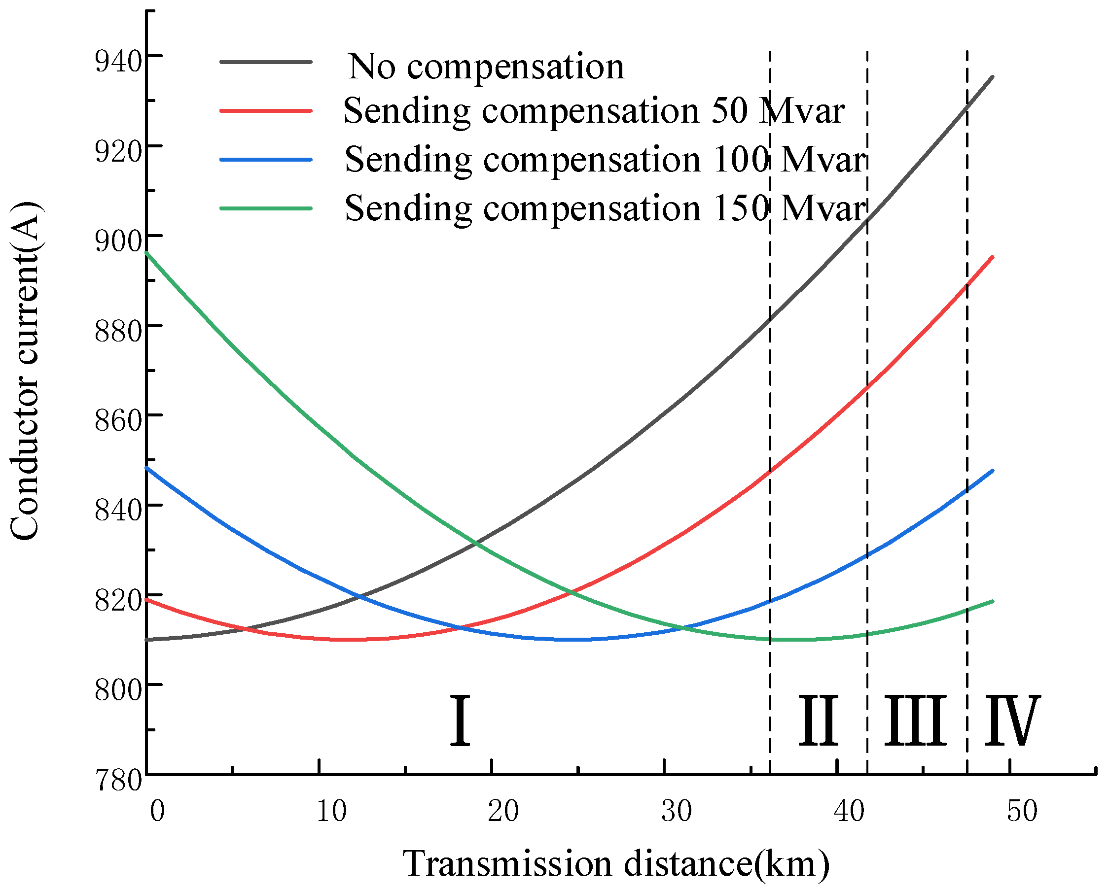
The reactive power compensation capacities at the sending end were set to 0, 50 Mvar, 100 Mvar and 150 Mvar, corresponding to the no-compensation, under- compensation, critical-compensation and over-compensation scenarios, respectively. Subsequently, the current distribution curves along the submarine cable under different reactive power compensation schemes can be obtained by Equations (1) and (2), as shown in
Figure 3 [
6].
As shown in
Figure 3, in the uncompensated scenario, the current in the submarine cable gradually rises from the sending end to the receiving end, leading to the current at the receiving end being notably higher than that at the sending end. Given that the entire submarine cable line typically employs a uniform specification, this non-uniform current distribution is detrimental to the efficient utilization of the submarine cable’s transmission capacity. After reactive power compensation is applied at the sending end, the current at the receiving end of the submarine cable is significantly reduced, and the non-uniform current distribution along the submarine cable is effectively mitigated. Nevertheless, for the case of under-compensation and critical-compensation, the current at the receiving end of the submarine cable remains at the maximum value along the entire line. Given that the reactive power compensation device operates continuously, and taking into account the valid cumulative duration of full-power generation of offshore wind power, wind farms typically do not adopt the over-compensation strategy to prevent long-term waste of reactive power compensation capacity. Hence, when analyzing the overheating issue of the directional drilling section near the receiving end of the submarine cable, the greater heat generation of this section compared to other sections cannot be overlooked.
3. Analysis of Heat Dissipation of Directional Drilling Section of the Submarine Cable
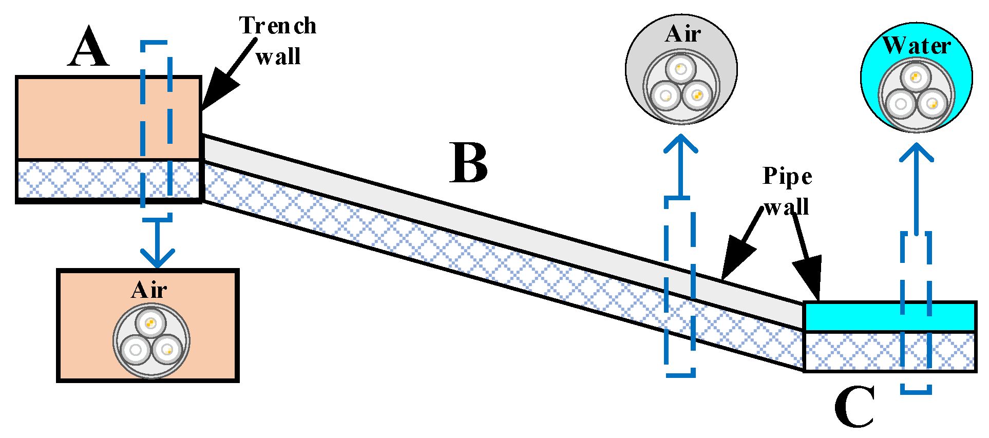
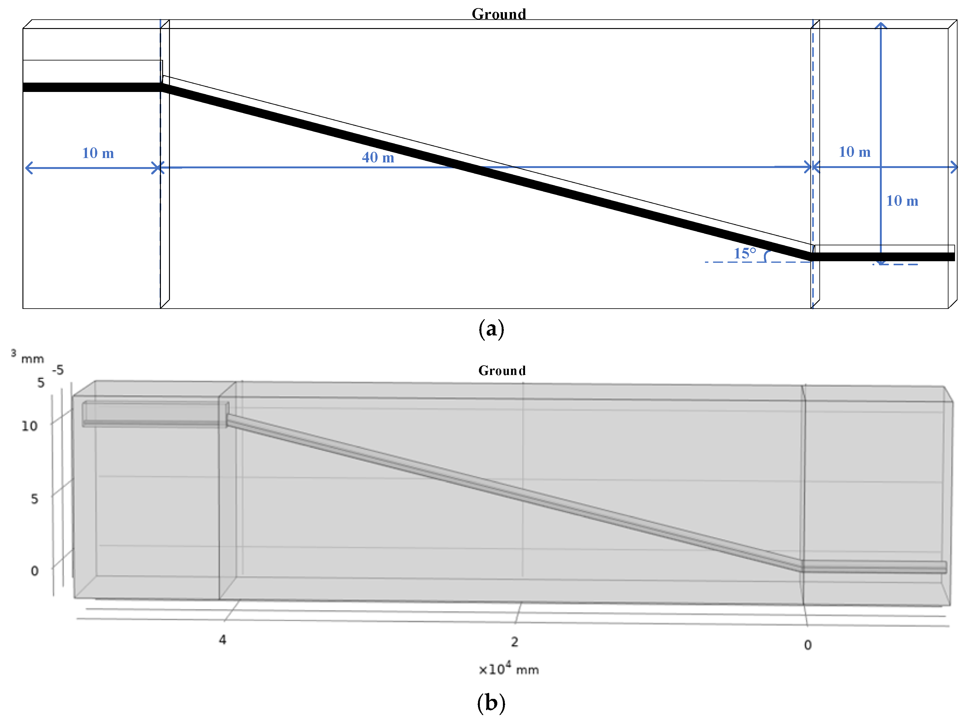
Before studying the heat dissipation characteristics of the directional drilling section of the submarine cable, referring to the actual submarine cable laying project, the submarine cable landing section can be approximately divided into three parts according to the differences in the operating environment of the submarine cable: the land cable trench section, the inclined entry section and the seabed horizontal section, as shown in
Figure 4. Among them, the submarine cable in the land cable trench section or the inclined entry section is surrounded by air, while the submarine cable in the seabed horizontal section is surrounded by water.
For the inclined entry section, due to the continuous change in the burial depth of the pipeline, the external heat dissipation environment of the pipeline also changes constantly, eventually leading to a significant axial heat transfer phenomenon inside the submarine cable in this section. In addition, the external heat dissipation environment near the interface of different parts of the submarine cable landing section also shows significant differences. Among the three sections shown in
Figure 4, the land cable trench section has the shallowest burial depth, whereas the seabed horizontal section has the deepest. Therefore, a 3D simulation model needs to be implemented to accurately estimate the heat exchange process between the submarine cable landing section and its surrounding environment [
22,
23,
24,
25,
26,
27].
The 220 kV 3 × 1000 mm
2 submarine cable with specific parameters as shown in
Table 1 was selected as the research object. Then, the 3D simulation model of the submarine cable landing section was built, and its geometric configuration was shown in
Figure 5. In
Figure 5, the horizontal lengths of the land cable trench section, the inclined entry section, and the seabed horizontal section were set to 10 m, 40 m and 10 m, respectively, and the burial depth of the seabed horizontal section was set to 10 m. It should be noted that the directional drilling submarine cable case studied in this paper neglects the slope variation of the coastline above the directional drilling section, which the IEC 60287 method considers to have the most severe overheating conditions. In cases where the coastline is inclined, the actual burial depths of the inclined entry section and the seabed horizontal section may be shallower than assumed, thereby mitigating the overheating risk for directionally drilled cables. Nevertheless, the simulation modeling approach presented in this paper remains applicable.
For the simulation model depicted in
Figure 5, the internal losses of the submarine cable, comprising conductor, dielectric, sheath, and armor losses, are calculated in accordance with the IEC 60287 method.
(1) Cable Loss Calculation
Conductor Loss:
where
Qc is the conductor heat generation power per unit length,
I is the load current,
ys is the skin effect factor,
yp is the proximity effect factor,
R0 is the DC resistance per unit length of the conductor at 20 °C, and α
20 is the temperature coefficient of electrical resistivity. For standard annealed copper,
α20 = 0.00392;
θ is the conductor operating temperature.
Insulation Loss:
where
ω is the angular frequency,
U0 is the phase-to-ground voltage,
δ is the dielectric loss factor of the insulation at system frequency and operating temperature,
c is the capacitance per unit length of the cable, and
ε is the permittivity of the insulation material; the typical value is 2.5,
Di is the outer diameter of the insulation layer, and
dc is the conductor diameter.
We respectfully note that the losses in the lead sheath and the armor of the submarine cable can be calculated following the methodology provided in IEC 60287-1-1.
(2) Boundary Condition Equations
a. First-type (Dirichlet) boundary condition—prescribed constant temperature at the boundary:
b. Second-type (Neumann) boundary condition—prescribed normal heat flux at the boundary:
c. Third-type (Robin or convective) boundary condition—known ambient fluid temperature and surface convection heat transfer coefficient:
where
T1 is the surface temperature of the heat-generating body, and
T0 is the ambient fluid temperature.
For the 3D simulation model in
Figure 5, the lower surface is set as the first-type (Dirichlet) boundary condition, and the deep soil temperature is set to 20 °C. The upper surface is set as the third-type (Robin or convective) boundary condition, and the temperature and the convective heat transfer coefficient of the atmosphere are set to 30 °C and 5 W/(m
2·K), respectively. The remaining surfaces are treated as second-type (Neumann) conditions. By applying the method for determining the axial adiabatic surface proposed in [
28], it can be observed that since the left end of the land cable trench section and the right end of the seabed horizontal section are far away from the interface of different parts of the submarine cable landing section, there is essentially no axial heat transfer process in their vicinity. Consequently, the ends of the simulation model can be designated as axially adiabatic surfaces. The key input parameters required for the simulation are summarized in
Table 2 [
28].
By using the established simulation model, the conductor temperature distribution of the submarine cable landing section can be obtained to analyze the differences in heat dissipation capacity of three parts shown in
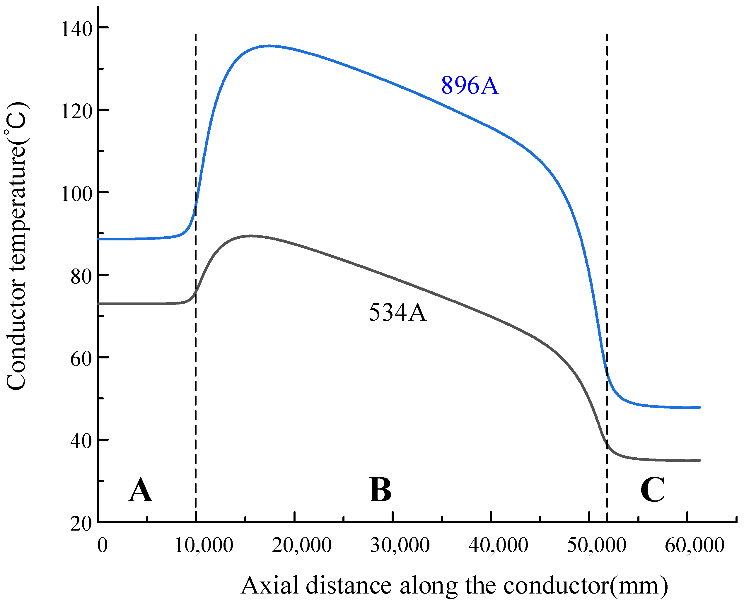
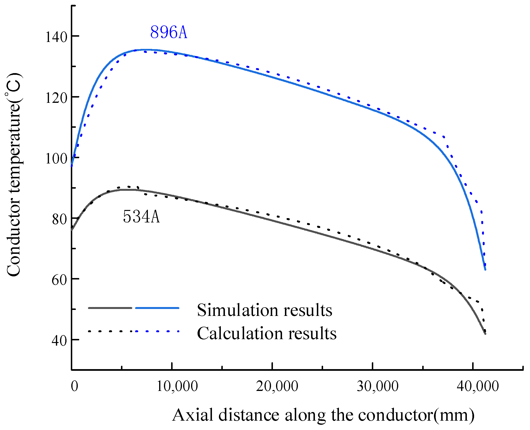
Figure 4. To reflect the differences in the ampacity of different parts of the submarine cable landing section, the submarine cable loads were set at 534 A and 896 A, respectively. Then, the conductor temperature distribution curves of the submarine cable landing section under different load conditions were obtained by the implemented 3D simulation model of the submarine cable landing section, as shown in
Figure 6. In
Figure 6, the left end of the land cable trench section was selected as the starting point for conductor temperature sampling, namely the origin of the coordinate axes.
As shown in
Figure 6, the hot spot of the submarine cable landing section is located at the inclined entry section. Commencing from the interface between the inclined entry section and the land cable trench section, the conductor temperature of the submarine cable increases rapidly and attains its maximum value near the interface. Subsequently, the conductor temperature of the submarine cable decreases gradually, reaching its minimum value in the pipe seabed horizontal section. In addition, for the land cable trench section and the seabed horizontal section, the influence range of axial heat transfer is limited, which proves the rationality of setting the ends of the simulation model as axial adiabatic surfaces.
It can also be observed from
Figure 6 that when the submarine cable load is 534 A, the hot spot conductor temperature of the directional drilling section approaches 90 °C. In contrast, under the same environmental conditions, according to the calculation by the simulation method, the hot spot conductor temperature of the seabed section approaches 90 °C when the submarine cable load is 976 A [
15]. This proves that the heat dissipation condition of the submarine cable in the seabed section is significantly better than the submarine cable in the directional drilling section. When considering the greater heat generation of the directional drilling section presented in the previous chapter, there is a significant mismatch in the transmission capacity between the seabed section and the directional drilling section of the submarine cable, which restricts the transmission capacity of the submarine cable.
To analyze the factors contributing to the formation of hot spot in the inclined entry section of the submarine cable, when the burial depth of the submarine cable is relatively shallow, the heat generated by the submarine cable is primarily dissipated to the atmosphere via the overlying soil. At this stage, as the burial depth increases, the thermal resistance between the submarine cable and the atmosphere continuously rises, leading to an increase in the temperature of the submarine cable. Nevertheless, when the burial depth surpasses a certain threshold, the far-end effect caused by water filling at the submarine cable terminus becomes significant. This phenomenon establishes a more efficient heat dissipation channel, allowing a substantial portion of the heat generated by the submarine cable to be dissipated through the water-filled section at the far end. As the burial depth increases, the influence of this far-end water filling intensifies, leading to a marked decrease in the temperature of the submarine cable. Consequently, for the inclined entry section of the submarine cable, the conductor temperature will exhibit a trend of initially rising and then falling as the burial depth increases.
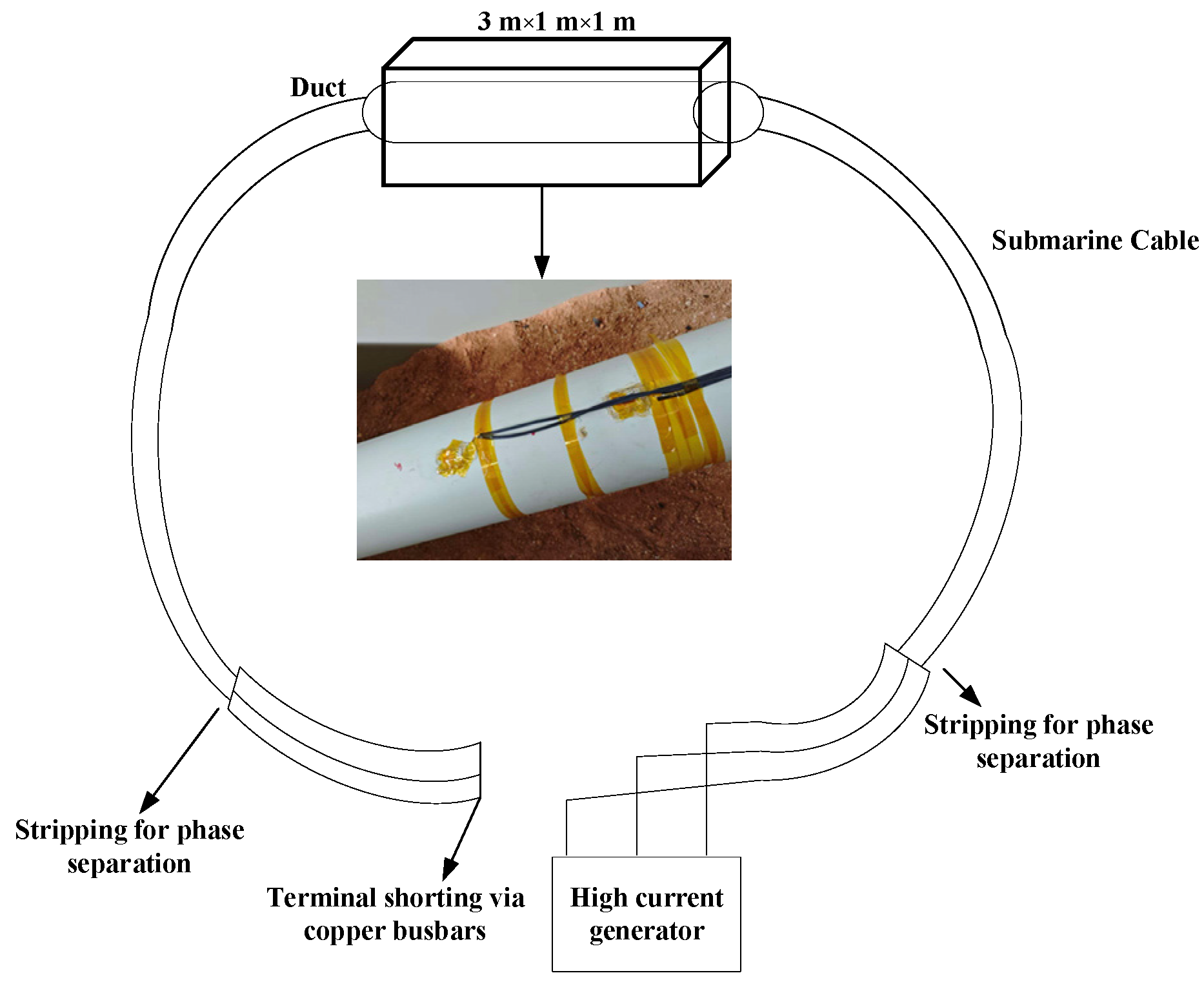
To validate the accuracy and reliability of the simulation results, a simplified temperature rise test system was specifically designed for the submarine cable landing section. In
Figure 7, the experimental subject was a 66 kV, 3 × 95 mm
2 three-core AC XLPE submarine cable. An environmental simulation chamber was employed to replicate the specific conditions of the directional drilling segment. The experimental procedure was as follows: Firstly, the instrumented cable (equipped with temperature sensors) was positioned at the center of the chamber to simulate the authentic heat dissipation environment. Subsequently, the cable was inserted into the directional drilling pipe, and the annulus was backfilled with standard soil, thereby successfully reconstructing the thermal boundary conditions of the directional drilling scenario.
Following a rigorous verification of the electrical connections, the variable transformer was activated to inject current into the cable. The temperature rise evolution was recorded continuously until the conductor temperature stabilized at 90 °C. To minimize experimental uncertainty and ensure data reliability, tests were conducted under two distinct load conditions. Correspondingly, simulation models were established based on the identical experimental boundary conditions and parameters to validate the accuracy of the proposed modeling method.
Table 3 summarizes the comparative results between the numerical simulations and the experimental measurements.
A comparative analysis of the experimental results reveals a negligible discrepancy between the numerical simulations and the experimental measurements. Specifically, under an input load of 339 A, the absolute error was merely 1.1 °C. Furthermore, the error across all tested load conditions remained consistently below 2 °C. Based on these findings, it can be concluded that the proposed three-dimensional multi-physics coupled simulation model for the submarine cable directional drilling section demonstrates high accuracy and reliability.
5. Improved Thermal Rating Method for the Directional Drilling Section of the Submarine Cable
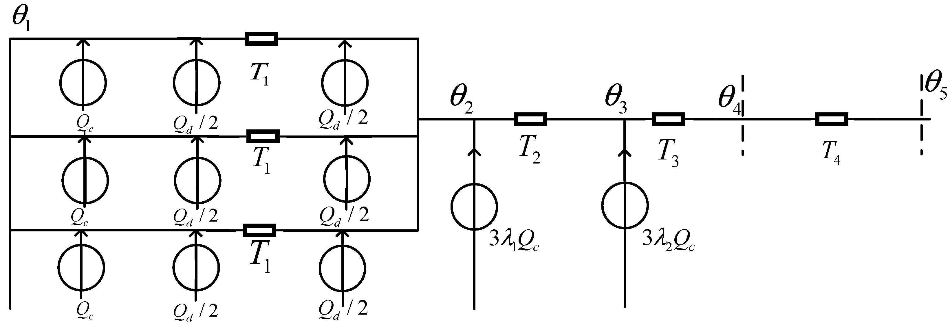
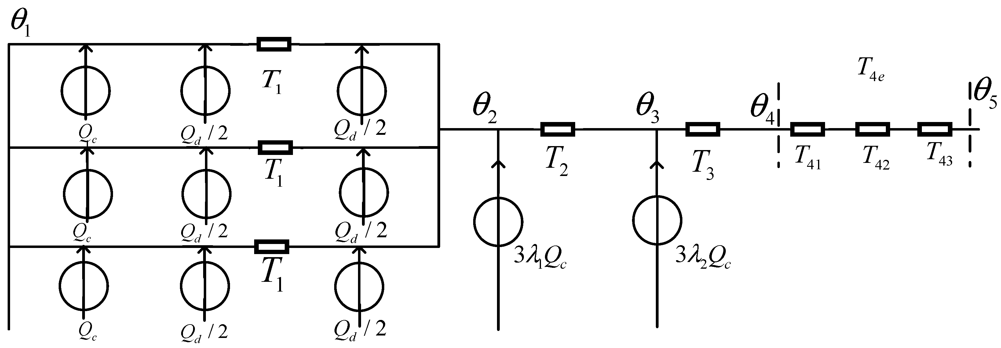
Based on the quasi-3D thermal circuit model presented in
Figure 10, an improved thermal rating method for the directional drilling section of the submarine cable can be proposed to achieve accurate calculation of the conductor temperature, which can be regarded as an effective supplement to the IEC 60287 method.
As analyzed earlier, the temperature at the starting and ending nodes can be calculated directly using Equations (18) and (19).
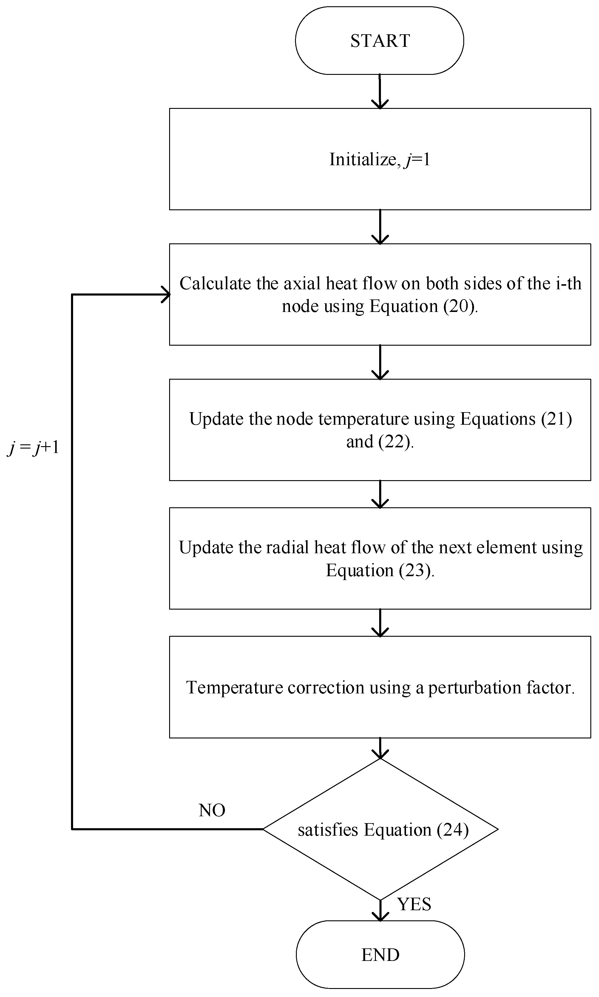
For the remaining nodes, the improved thermal rating method is illustrated using the
j-th iteration (where 1 ≤
j) as an example. First, the axial heat flows on both sides of the
m-th node are calculated using Equation (20).
The node temperature is then updated using Equations (21) and (22).
Finally, the radial heat flow for the next micro-element is updated via Equation (23) and
α20 = 0.00393 °C
−1.
The iteration stops and the temperature results are output when the calculated maximum temperature satisfies Equation (24).
Moreover, if the temperature of the
m-th node
is the maximum, then when
satisfies
≤
or
≤
, the node temperature is updated through Equation (25).
If the temperature of the m-th node
is not the maximum, then when
satisfies
<
<
or
>
>
, the node temperature is re-updated through Equation (26).
where
n is the total number of the cable units, and
o is the perturbation factor. For the
m-th temperature node, when
>
,
o takes a positive value, and when
<
,
o takes a negative value.
Figure 11 illustrates the schematic of the iterative process for the improved evaluation method of submarine cable temperature calculations.
Referring to [
29,
30], the simulation method capable of accurately simulating the three-dimensional temperature distribution was chosen as the comparison object to verify the accuracy of the improved thermal rating method developed based on the quasi-3D thermal circuit model. Given that the maximum temperature arises in the inclined entry subsection, the conductor temperature distribution results of this subsection obtained by the proposed improved thermal rating method and the 3D simulation model shown in
Figure 5 were compared, as illustrated in
Figure 12.
As depicted in
Figure 12, the curves derived from numerical simulation and the proposed improved thermal rating method demonstrate favorable agreement, thereby accurately capturing the temperature distribution characteristics of the cable conductor in the inclined entry subsection. Furthermore, to quantitatively assess the consistency between the two sets of results, the average absolute error Δ
Tavr and coefficient of determination were calculated using Equations (27) and (28), respectively, with the corresponding results summarized in
Table 3.
where
θcai is the calculated temperature of each conductor unit,
θsimi is the simulated temperature of each conductor unit,
is the average value of the simulated temperature, and
n is the total number of the conductor unit.
According to the error analysis results summarized in
Table 4, the average absolute error is consistently maintained below 2 °C, which indicates that the proposed improved thermal rating method exhibits satisfactory accuracy. Under varying load conditions, the coefficients of determination corresponding to the three curves all exceed 0.95, demonstrating a strong linear correlation between the analytical calculation results and numerical simulation results. Furthermore, the application of the improved thermal rating method developed based on the improved thermal circuit model enables accurate characterization of the thermal behavior of the inclined entry subsection within the directional drilling segment of the submarine cable. With appropriate modifications, the method remains applicable to scenarios involving burial.
6. Ampacity Improvement Strategy for the Directional Drilling Section of the Submarine Cable
Based on the aforementioned simulation study and thermal circuit analysis, it can be concluded that the enclosed air domain between the submarine cable and the pipeline is the main factor that hinders heat exchange between the submarine cable and the outside environment, thereby inducing overheating in the directional drilling section of the submarine cable. If the heat exchange capacity between the submarine cable and the inner wall of pipeline can be effectively enhanced, it is possible to alleviate the problem of mismatched transmission capacity in the directional drilling section of the submarine cable [
31].
Considering the abundant water resources near the landing section of the submarine cable, and inspired by the water-cycle-based ampacity enhancement study for land cable duct installations proposed in [
32], a circulating water capacity enhancement system was adapted and applied to the directional drilling section of the submarine cable. This approach aims to improve the transmission capacity of the submarine cable in this section and achieve ampacity matching within the directional drilling section.
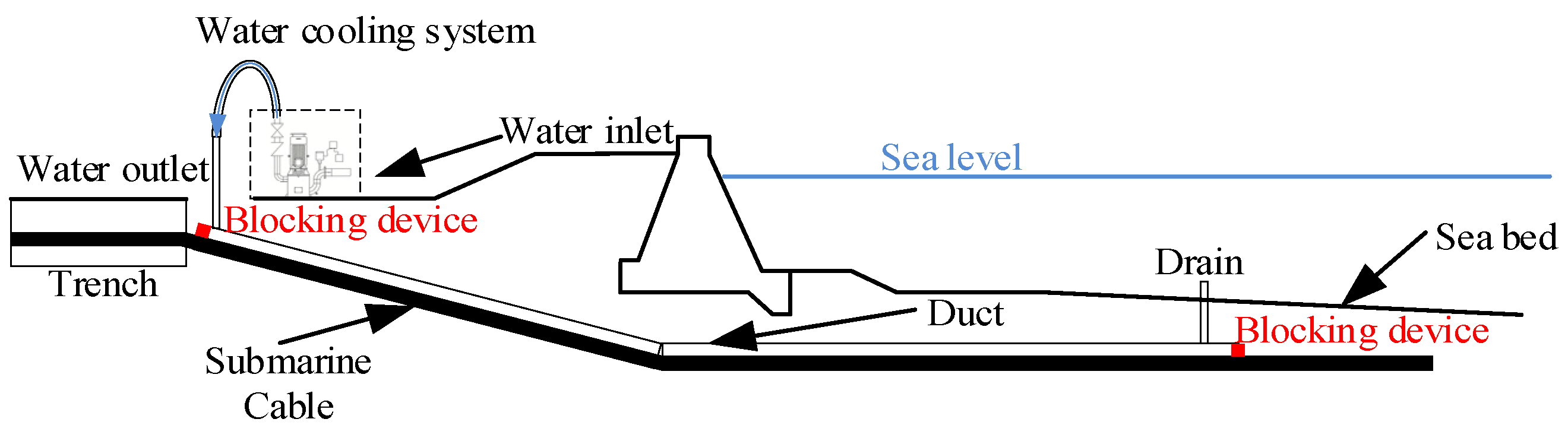
The specific implementation method of the water cycle designed for the directional drilling section of the submarine cable is shown in
Figure 13. Intake and outlet ports are set up near the directional drilling pipe ports located on land and on the seabed, respectively. The cycling water is drawn from the sea and injected into the directional drilling pipe through the intake port, and is finally discharged into the sea through the outlet port. It is worth noting that the top of the outlet should be at a certain height above the seabed plane, and the blind plate can be installed near the outlet to mitigate the sedimentation caused by the erosion of ocean currents. In addition, the sealing flange should be installed at the end of the directional drilling pipeline located on the seabed to prevent the backflow of silt and sand from clogging the pipeline. Similarly, a blockage should also be installed at the end of the directional drilling pipeline on land to prevent water from overflowing from the end. For the water circulation system shown in
Figure 13, under normal conditions, the water inside the directional drilling pipe is in a full state. Since the blow-off port is located below sea level, in order to ensure that the water in the directional drilling pipe completes the circulation and maintains a certain flow rate at this time, it is necessary to increase sufficient water pressure at the water inlet. The measure can also prevent the problem of sediment blockage at the water outlet and maintain the pressure within the pipeline.
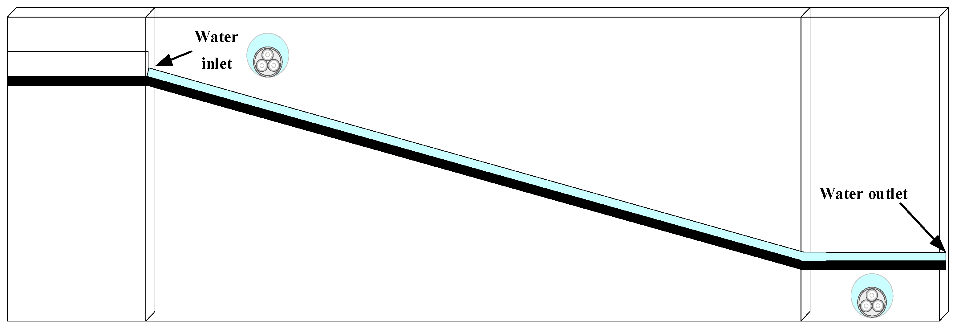
Based on the proposed method for implementing water circulation inside the directional drilling pipeline, the corresponding 3D simulation model was developed for the submarine cable landing section described in
Section 2, as shown in
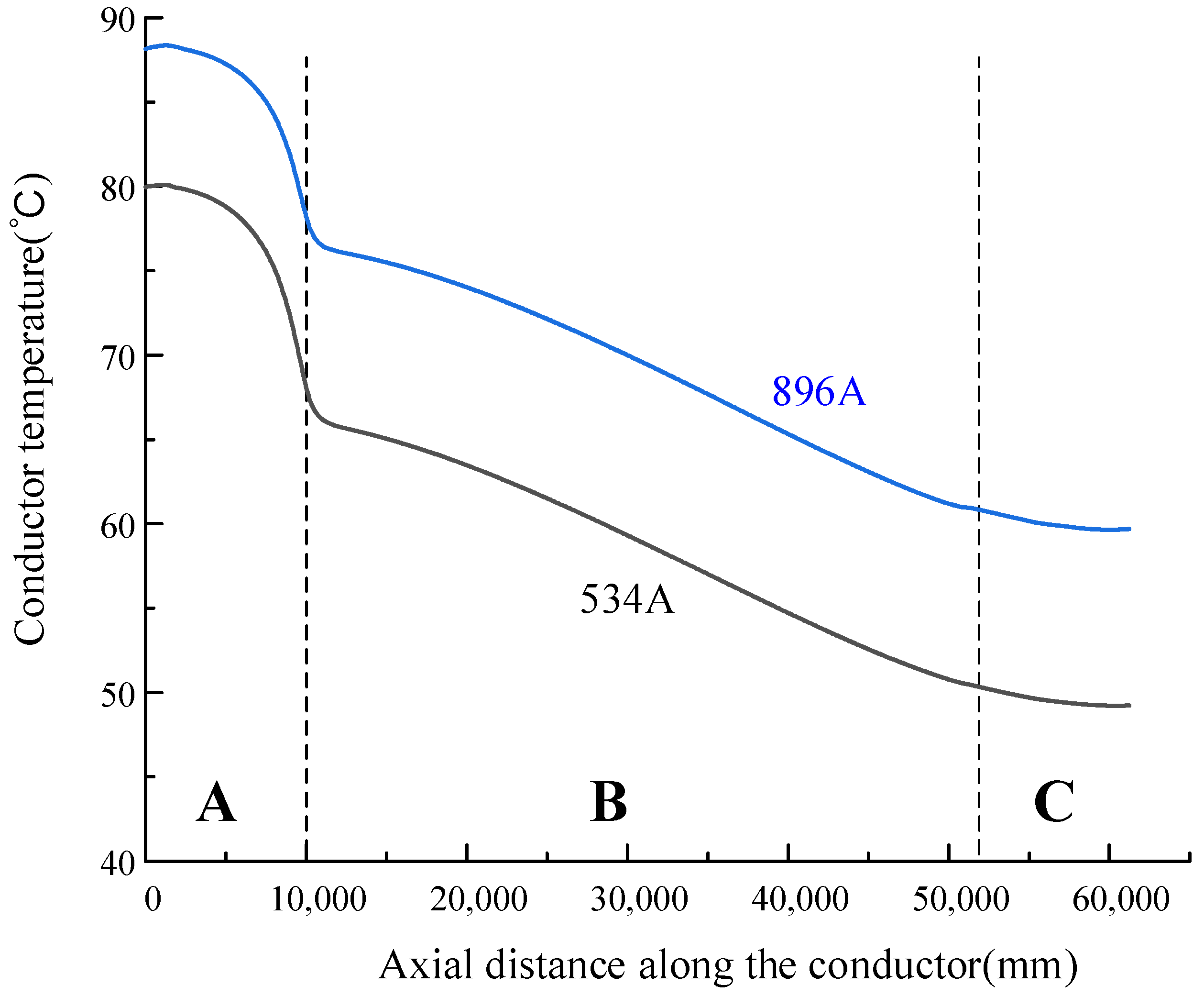
Figure 14. To simulate the water circulation, the land-side pipe opening was set as the inlet with an initial flow velocity of 0.5 m/s and an inlet water temperature of 20 °C, and the seabed-side opening was set as the outlet with backflow suppressed. Eventually, through the heat flow coupling calculation function of COMSOL, the analysis of the temperature field and fluid field within the pipeline can be achieved. Using the developed simulation model for the directional drilling section of the submarine cable with water circulation, the conductor temperature distributions along the landing section under different load conditions can be obtained as shown in
Figure 15.
As shown in
Figure 15, the application of the water cycle leads to a significant change in the temperature distribution characteristics of the conductor in the submarine cable landing section. The hot spot of the submarine cable landing section shifts from the inclined entry section of the directional drilling pipe into the soil to the land cable trench section. At this time, compared with the situation without using the water cycle, the maximum temperature of the submarine cable in the land cable trench does not change, while the maximum temperature of the submarine cable in the directional drilling pipe decreases significantly. As a result, the water cycle mode can effectively improve the overheating operation problem of the submarine cable in the directional drilling pipe.
In practical offshore wind farm projects, submarine cables are typically manufactured with uniform cross-sections for reliability. However, when the directional drilling section becomes a thermal bottleneck, the entire cable must be oversized to accommodate its reduced ampacity, which leads to material overdesign and unnecessary costs along most of the route. Applying the proposed circulating water capacity enhancement system can effectively reduce investment while enhancing transmission capacity and economic efficiency.
7. Conclusions
In this study, we analyzed the transmission load for the submarine cable directional drilling section, established a 3D simulation model, and proposed an improved thermal rating method. To address the overheating problem in the inclined entry section, a water circulation system was introduced, which effectively improves the transmission capacity of submarine cable in the directional drilling section. The main work can be summarized as follows:
(1) A distributed parameter model for the long-distance submarine cable was established. The differences in transmission load among various cable sections under different reactive power compensation strategies were calculated. Through the analysis of the load current distribution of a 3 × 1000 mm2 three core submarine cable at different compensation levels, it was discovered that the load current in the landing section is generally higher than that in the seabed section, which makes it a hidden bottleneck point for transmission capacity.
(2) A 3D simulation model was developed for the submarine cable in the directional drilling section, taking into account the axial heat transfer in the cable landing section. The ampacity of the land cable trench section is 896 A, whereas that of the inclined entry section is 534 A, leading to a transmission capacity gap of over 360 A. The results verify a severe overheating problem in the directional drilling section of the submarine cable.
(3) A thermal model was established for the directional drilling section of the submarine cable. Moreover, by taking into account the influence of axial heat transfer and deep soil temperature, a quasi-3D thermal model for the inclined entry section is proposed. The thermal evaluation of the directional drilling section of the submarine cable has been successfully accomplished. Based on this, an improved thermal rating method for the inclined entry section is developed. The absolute average error remains below 2 °C, and the coefficients of determination for the three curves all exceed 0.95. These results indicate that the thermal behavior of the inclined entry section of the submarine cable laid in the directional drilling duct can be accurately described.
(4) The proposed water circulation system has been demonstrated through numerical simulations to effectively reduce the conductor temperature within the pipe, thereby enhancing the cable’s ampacity. Compared to the scenario without active cooling measures, the simulated results show a substantial temperature reduction, which enables a significant improvement in the thermal performance of the submarine cable in the directional drilling section. With appropriate modifications, the method remains applicable to scenarios involving shallow burial. Experimental validation of this method is planned as part of future work.




 ,
,