Review

Advancing Electrochemical Energy Storage: A Review of Electrospinning Factors and Their Impact

1
Beijing Key Laboratory of Advanced Functional Polymer Composites, College of Material Science and Engineering, Beijing University of Chemical Technology, Beijing 100029, China
2
Pakistan Embassy College, Sanlitun, Chaoyang District, Beijing 100600, China
*
Author to whom correspondence should be addressed.
Energies 2025, 18(9), 2399; https://doi.org/10.3390/en18092399
Submission received: 24 January 2025 / Revised: 3 February 2025 / Accepted: 25 April 2025 / Published: 7 May 2025

Abstract

:
The imperative for sustainable energy has driven the demand for efficient energy storage systems that can harness renewable resources and store surplus energy for off-peak usage. Among the numerous advancements in energy storage technology, polymeric nanofibers have emerged as promising nanomaterials, offering high specific surface areas that facilitate increased charge storage and enhanced energy density, thereby improving electrochemical performance. This review delves into the pivotal role of nanofibers in determining the optimal functionality of energy storage systems. Electrospinning emerged as a facile and cost-effective method for generating nanofibers with customizable nanostructures, making it attractive for energy storage applications. Our comprehensive review article examines the latest developments in electrospun nanofibers for electrochemical storage devices, highlighting their use as separators and electrode materials. We provide an in-depth analysis of their application in various battery technologies, including supercapacitors, lithium-ion batteries, sodium-ion batteries, potassium-ion batteries, lithium–sulfur batteries, and lithium–oxygen batteries, with a focus on their electrochemical performance. Furthermore, we summarize the diverse fabrication techniques, optimization of key influencing factors, and environmental implications of nanofiber production and their properties. This review aims to offer an inclusive understanding of electrospinning’s role in advancing electrochemical energy storage, providing insights into the factors that drive the performance of these critical materials.

1. Introduction

Presently, scientific research in the energy field faces many issues, such as air pollution, climatic change, and depletion of fossil fuel resources [1,2,3,4,5,6]. Numerous studies have been conducted to address these challenges. It has been documented that some advanced nanomaterials, i.e., graphene [7,8,9], carbon nanotubes (CNTs) [10,11,12], polymeric nanofibers [13,14], etc., will remain essential in tackling the major challenges and achieving advancements in both technology and real-world applications. The changeable setup of the electrospinning and the diversity of its prominent operational parameters bring challenges and also opportunities to the industry of advanced adaptive materials. Nanofiber production using green polymers and solvents has seen significant scalability at the industrial level. However, scaling up still presents challenges, particularly regarding the large volumes of solvents needed for processing. This highlights the importance of optimizing the process. These challenges stem from gaps in the fundamental understanding of how electrospinning operates at the nanoscale, making it hard to predict the interactions between specific solute/solvent pairs [15,16,17,18,19,20].
There are various methods for creating nanofibers, such as centrifugal spinning [21,22], vapor–liquid–solid growth [23,24], sol–gel templating [25,26], and hydrothermal synthesis [27,28]. The simple operating and controllable electrospinning setup assists in obtaining the desired properties of the resultant fibers with diameters of about a hundred nanometers. The accumulation of such nanofibrous structures to a nonwoven porous web-like membrane is termed an electrospun fibrous membrane [29,30,31,32,33,34]. Numerous materials with their structural designs have been employed to improve the optimum performance. Among them, nanofibers have been broadly used due to their distinctive properties, i.e., high surface area, greater porosity, high flexibility, and excellent mass transfer ability [15,35,36,37]. The rapid development of the production of electrospun nanofibers has been broadly employed in various important applications, i.e., rechargeable batteries [38,39,40], supercapacitors [41,42,43], fuel cells [44,45,46], solar cells [47,48,49], hydrogen (H2) generation [50,51,52], carbon dioxide (CO2) reduction [53,54,55], etc. The invention of the battery was a focal element in the production of H2 by the electrolysis of water. Deiman and Troostwijk were the first to generate H2 with an electrostatic machine. Later on, the Volta battery inspired scientists, like W. Nicholson, A. Carlisle, and J. Ritter, to perform various experiments and explore various methods of hydrogen production. Their historical work laid the foundation for the creation of more advanced electrochemical techniques for H2 production, such as anion exchange membranes, solid oxide electrolysis cells, and polymer electrolyte membranes [56].
Historically, the electrospinning technique was initiated in the 1700s, when water behavior was studied under electrostatic observations. Afterward, in the late 1800s, electrodynamics principles were applied to elucidate the dielectric liquid excitation under an electric field, which eventually led to the invention of electrospinning by two renowned scientists, Cooley and Morton, in the early 1900s. The dielectric constant of water demonstrates its polarity, which plays a significant role in assessing the solvent properties. Typically, the dielectric constant is the ratio of a material’s absolute permittivity to that of free space [57]. The dielectric constant of a solvent reflects the degree of “free” charge produced within the polymeric solution during electrospinning [58]. This technique was invented back in the era of 1934, when a scientist named Anton Formhals spun a fiber from the blended solution of cellulose acetate/acetone. In 1981, “Donaldson” was one of the promising leading companies in nanofiber production applications that initially introduced advanced applications for commercial use, such as the air filtration technology Ultra Web®.
The substantial surface area and high porosity of the entirely interlinked pore structure assisted in high electrolyte uptake and the movement of ions across the membrane separator, indicating a promising candidate. Thus, electrospinning has played a significant role in new clean energy [59,60,61]. The utilization of nonwoven membrane technologies has become more attractive over the past decades because of their high separation efficiencies, reasonable costs, and simplicity of the process. They perform like an obstruction between two phases, allowing the materials to transfer from one part to another [62,63]. The main function of the separator is to avoid the joining of both positive and negative electrolytes, so it acts as a barrier that permits the passage of ions to complete the electric circuit. The performance of these devices directly depends on the kind of material and structure of the membrane separators [64,65,66].
Predominantly, secondary storage devices, for example, lithium-ion batteries (LIBs), are employed by many consumers as they provide high energy density, a longer life cycle duration, low self-discharge, and greater operational electrical energy. Such batteries work electrochemically and depend on the instantaneous transmission of electrons via an external circuit and the cyclic relocation of lithium ions across a microporous membrane separator to the electrolyte. The highly porous structure of the nonwoven membrane separator has an excellent effect on ionic conductivity. An ideal separator should have zero ionic resistance, which can be attained by a high porosity [67,68]. Polyolefin membrane separators, such as polyethylene and polypropylene, have become the primary materials in the market of LIBs over the decades due to their superior qualities, for instance, cost-effectiveness, good tensile properties, electrochemical stability, and thermal shutdown properties. On the contrary, there exist some major issues in the vehicular storage of non-polarity and low thermal stability [69,70,71].
Undoubtedly, the fundamental considerations, such as process parameters, material properties, and environmental conditions, of a spinning process are vitally influenced because all these factors dictate the desired characteristics of the fibers and, hence, formulate the diversity in the performance of a storage device. So, we spotlighted the various aspects influencing electrospinning and electrospun polymeric materials for energy storage devices, i.e., rechargeable batteries and supercapacitors. Figure 1 illustrates a comprehensive review of a decade’s research on various electrospun nanofibers in lithium-based batteries as electrodes, separators, gel polymer electrolytes (GPEs), and solid-state electrolytes (SSEs). The histogram shown below demonstrates a significant rise in the number of articles published from 2015 to 2024, as listed in the Web of Science database.

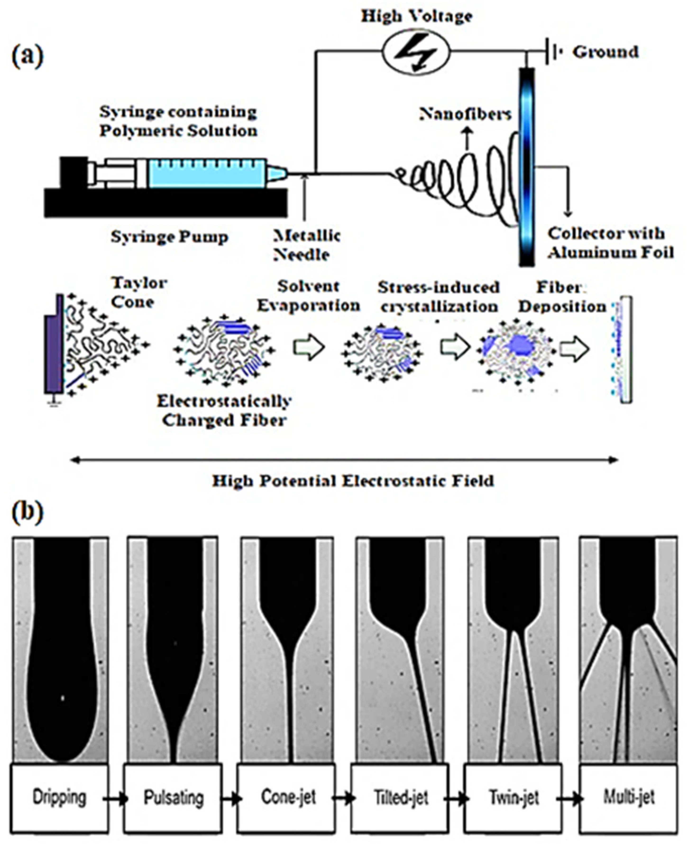
2. Fundamental Features of Electrospinning

Principally, electrospinning operates through the electrohydrodynamic phenomenon. When a polymer solution or melt is fed, surface tension is created at the needle’s tip, which is driven by electrostatic forces to form a filament fiber. The high-voltage power supply used can be either a direct current (D.C.) or an alternating current (A.C.). When the voltage of the electric field increases, gradually, a hemispherical-shaped fluid draws out at the tip of the metallic capillary needle that forms a conical body called the Taylor cone. Steadily, the electric field approaches a value that overcomes the surface tension. At such a critical stage, a charged filament jet of the polymer melt is emitted from the tip of the Taylor cone. The evaporation of the solvent takes place in the air, which eventually solidifies the jet in the form of a fine strand known as a fiber. The charged polymeric fiber is arbitrarily accumulated on a flat or rounded aluminum collector. Owing to the development of such technology, various researchers have built up more advanced systems that can prepare more multifaceted nanofibrous configurations with a better approach. This type of standard assembly for electrospinning is available at almost every research institution, as shown in Figure 2a [30,72,73].
A typical electrospinning assembly comprises three basic components, as shown in Figure 3b:
i.
A syringe pump (including a syringe and syringe needle);
ii.
Metal collector (stationary or rotary);
iii.
High-voltage supply unit.
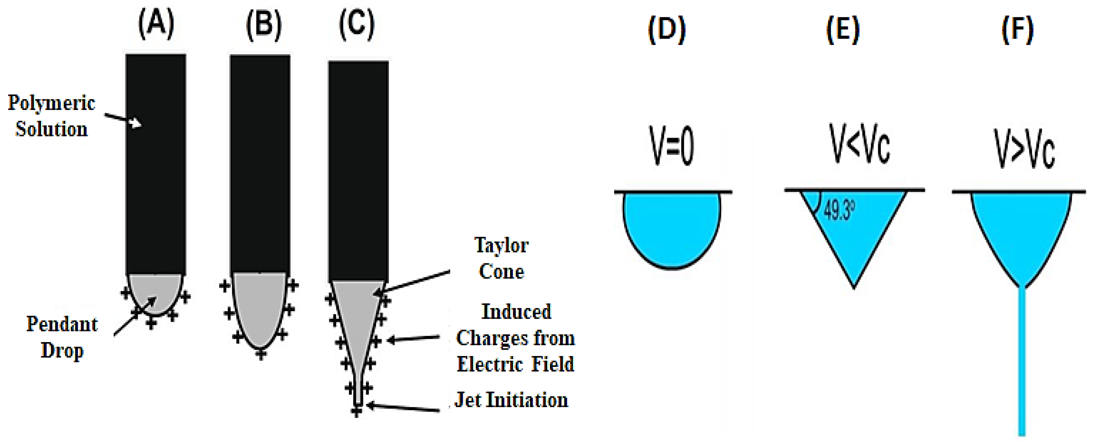
The different instants during nanofiber fabrication are also drawn. These fibers experience an electrostatic force in a high-potential field and become charged. The high potential electric field influences the polymeric fibers by interacting with the surface charge carriers in the polymeric solution. The electrostatic forces drive the elongation and thinning of the fibers, while the repulsion between the charge carriers contributes to the formation of fine and well-controlled fibers. The applied voltage can be adjusted to obtain the optimum fiber diameter and structure [32,73].
In general, an electrospinning process consists of four standard consecutive steps as follows:
i.
Charging of liquid droplets and creation of Taylor’s cone;
ii.
Elongation of the charged jet;
iii.
Thinning of the jet in a high-potential electrostatic field;
iv.
Deposition of fibers on a metal collector [32,74,75].
Figure 2. Schematic illustration of (a) the electrospinning equipment setup along with different moments during fiber formation [30]. (b) Extruded jet regimes are produced by increasing the applied voltage gradually [76] (reproduced with permission from ACS, 2013).
Energies 18 02399 g002
In the electrospinning process, the polymer solution is fed through the needle at a steady flow rate using a syringe pump. Upon applying a voltage using the power supply, both positive and negative charges appear on the liquid. Increasing the voltage gradually causes an increase in the density of surface charges on the droplets. While the surface tension of the liquid is supposed to reduce the surface free energy and sustain the spherical shape, the electrostatic forces tend to distort the shape of the droplet. Therefore, the surface area of the droplet gets bigger and attenuated [77,78].
The emerging jet can exhibit different electrohydrodynamic behaviors in the electrostatic field, which can also be considered as jetting regimes. As the applied voltage increases, the emerging jet undergoes a series of transformations, progressing from dripping and pulsating to forming a cone-jet, tilted jet, twin jet, and, eventually, a multi-jet, as shown in Figure 2b [79]. Presuming that the droplet is a good conductor, the electrostatic pressure (pe) exerted on the droplet can be determined using the expression pe = εE2/2, where ε is the dielectric constant, also called the permittivity of the medium, and E is the electric field intensity. The capillary pressure (pc) produced by the surface tension is described by the “Young–Laplace” equation as pc = 2γ/r, where γ is the surface tension and r is the average radius of curvature of the surface. When the applied voltage attains sufficient strength at a critical voltage Vc, pe is exceeded, which implies that the electrostatic forces will be high enough to control the surface tension of the liquid. Consequently, the droplet will reshape into a conical formation. In such a situation, Vc can be determined using the following expression:
Vc2 = 4H2/h2 [ln (2h/R) − 1.5] (1.3πRᵞ) (0.09)
where H represents the distance between the needle tip and the collector, h denotes the needle’s length, and R represents the external radius of the needle. The units of all parameters (H, h, and R) used are in centimeters, whereas γ is in dyne/cm and voltage is in kV [80,81,82].

3. Approaches for the Fabrication of Electrospun Membranes

3.1. Single-Spinneret Electrospinning

The single-needle/spinneret arrangement is frequently used because it is simple and convenient. A metallic needle is mostly employed in conventional electrospinning, wherein the needle tips to the plate, creating an uneven electrostatic field distribution. It is evident from its name that only one needle/spinneret is used. Thus, just one polymer solution is pumped by a single surgical syringe, as shown in Figure 3c. Such a setup is more suitable for institutional research laboratories as it can quickly produce nanofibrous membrane samples. By organizing the parametric conditions, diverse forms of membrane structures, morphologies, densities, and functionalities can be fabricated according to the optimum requirements. Figure 3 demonstrates other different spinneret arrangements for use in electrospinning. The low flow rate of a single needle has confined the applications of electrospinning at the industrial level. Multiple needle arrangements have been brought up to raise the flow rate. On the other hand, multiple needles make the distribution of the electric field much more complicated. To rectify such an issue, alternative electrospinning arrangements with more evenly distributed electric fields must be built [83,84].

3.2. Multi-Spinneret Electrospinning

Electrospinning is not just confined to a single spinneret arrangement, but it is also composed of a hybrid nanofiber membrane that contains various combinations of polymers. A multi-spinneret electrospinning setup can be utilized for this purpose, enabling the simultaneous electrospinning of two or more solutions accumulated on a single collector. In comparison, multi-jet electrospinning can fabricate nanofibers of large areas faster and faster than single-jet electrospinning. A multi-needle system is arranged to increase production capacity. Such a system still needs to be studied more, as it can be designed to increase productivity and construct a special morphology of fibers. A multi-spinneret or needle electrospinning setup is executed in multiple configurations. For instance, a linear arrangement of spinnerets located side by side and another one could be arranged in a circular design (Figure 3d,e) [85,86].

3.3. Coaxial Electrospinning

The coaxial electrospinning type of arrangement is said to be an extended form of electrospinning, wherein two polymeric solutions or melts can be spun at the same time. These solutions are regarded as the core and the sheath layer of fiber that are always fed separately into the primary and subsidiary syringes, respectively, as shown in Figure 3a,b, which contains a schematic view of the coaxial spinning process along the needle setup. To perform an ideal operation, both core and sheath solution parameters, such as viscosity, miscibility, conductivity, vapor pressures, and feed rate, are significantly important. In an unusual situation where a blend of electro-spinnable and non-electro-spinnable solutions is employed, the concentration of the solution should be sufficiently high to create homogeneous core/sheath fibers [87,88].
The coaxial electrospinning technique was used to fabricate core/sheath nanofibers composed of strontium titanate and nickel oxide (SrTiO3-NiO). A solution was prepared by dissolving polyacrylonitrile (PAN) in dimethylformamide (DMF) at a weight ratio of 10:90. Nickel oxide (NiO) was then mixed into this solution to create the outer (sheath) layer. After electrospinning, fibrous membranes were collected from the collector. These membranes underwent a calcination process at 600 °C for two hours to eliminate volatile components and induce crystallization. Scanning electron microscopy (SEM) was employed to analyze the surface morphology and fiber dimensions. Figure 3h,i display the SEM images of the fibers before and after calcination. Notably, the fiber diameter decreased post-calcination, with the average diameter reducing from approximately 500 nm to 400 nm. The surface morphology of the fibers also changed, exhibiting slight roughness and a few bumps, attributed to the release of water vapor and other volatile substances during thermal treatment. The shrinkage observed in the fibers is likely due to the high-temperature exposure, which may have also contributed to the formation of a dense crystalline phase [89]. This method allows for the fiber properties by altering the cross-sectional shape through a pre-designed spinneret. For instance, factors like morphology, uniformity, tensile strength, and fiber diameter can be readily modified by adjusting the processing conditions.
The wet spinning of polyvinylidene fluoride (PVDF) fibers has excellent potential for piezoelectric nanogenerator (PENG) applications, offering advantages in fiber characteristics and the production process. Yue et al. [90] utilized a three-layer composite fiber structure to develop piezoelectric nanogenerators (PENGs) and stress sensors. The fibers consisted of a core layer made of liquid metal (LM), which served as the inner electrode, an intermediate layer of PVDF hollow fibers, and an outer layer of copper and silver nanoparticles (Cu@AgNP), functioning as the external electrode. The LM, acting as a 3D electrode, could deform under pressure, generating an electric charge. The PVDF hollow porous fibers were fabricated using a non-solvent phase separation technique. The piezoelectric test of the prepared composite nanofibers revealed an output voltage of 410 mV, indicating superior electrical characteristics. The results highlight the considerable potential of this technique for use in wearable applications. Hence, coaxial electrospinning is an excellent approach for polymeric solutions that are hard to spin or those polymers that are insoluble/partially soluble. We can select a completely miscible solution, either as a core or the sheath layer, that could act as a carrier for such types of “complex” polymers. Moreover, such an electrospinning arrangement is also employed to produce hollow fibrous membranes exclusively.
Figure 3. (a) Schematic view of the coaxial electrospinning process; (b) coaxial needle SEM micrographs of coaxial electrospun nanofibers (h) before calcination and (i) after calcination [89] (reproduced with permission from Wiley, 2021). (cg) Different spinneret configurations for the electrospinning of neat and composite micro/nanofibers [91] (reproduced with permission from Material and Engineering, 2013).
Energies 18 02399 g003

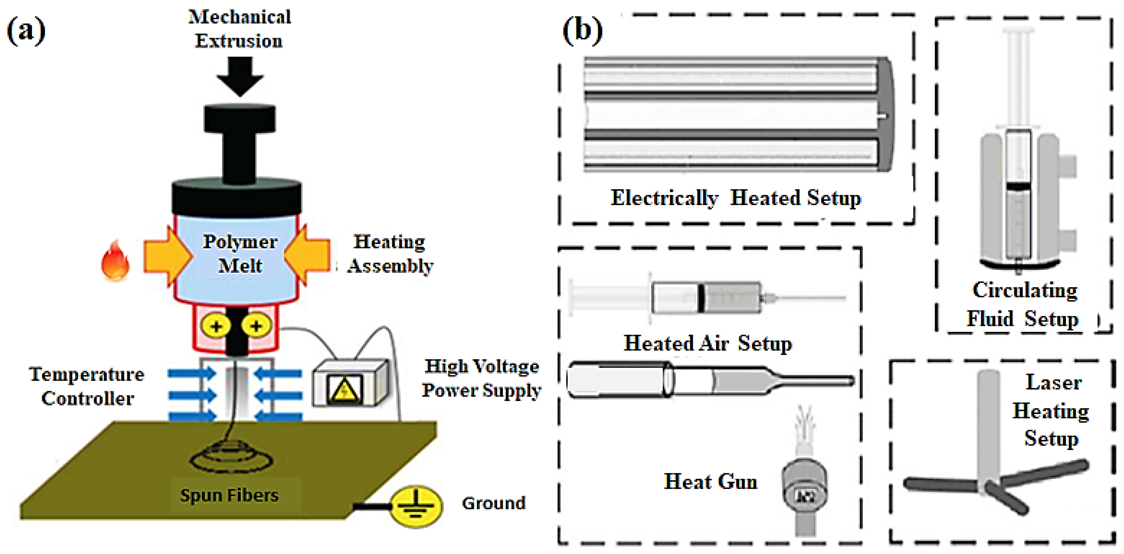
3.4. Melt Electrospinning

Lately, melt electrospinning has gained significant attention for producing nanofibers from polymers. This method is advantageous because it does not require solvents, is cost-effective, and is better for the environment. The fibers prepared by this method offer greater mechanical stability than the conventional solution electrospinning technique, where the solution electrospinning system allows for polymers that are dissolved homogeneously in some solvent system. In this case, it is not possible to create fibers such as polytetrafluoroethylene (PTFE), PP, and PE. In this situation, melt electrospinning is employed to spin such polymers. Meanwhile, melt electrospun fibers appear as an alternative to conventional solution electrospinning without any residual solvent, which provides a prospect to use them in medical fields, i.e., tissue engineering, wound dressings, etc. [92,93]. Figure 4a,b demonstrate the schematic setup of melt electrospinning and its different heat configurations for the melting process of a polymer. Concerning the material characteristics, various aspects of the polymer melting can affect the melt electrospinning; however, viscosity is the most contributing factor since the viscosity of a polymer melt is significantly higher, typically by an order of magnitude, compared to that of polymer solutions. So, it is necessary to decrease it by applying an appropriate thermal treatment, e.g., increasing the polymer melt temperature with no degradation or adding some additives such as cationic surfactants [94].
In general, this method is employed for the following reasons:
i.
Accessibility of various engineering thermoplastics, i.e., PP, PE, PC, etc. These are not soluble in normal solvents at room temperature, so they are difficult to execute using solution electrospinning.
ii.
Health protection is provided to the operators due to the lack of solvent involvement.
iii.
Ecofriendly, as there is no smoke or toxicity hazards released into the environment.
iv.
The surface of fibers compares to fibers produced by solution electrospinning, containing tiny pores on the exterior.
v.
Ease in the fabrication of microporous-based fibrous films that can be employed in various applications.
Table 1 illustrates a comparative overview of both solution and melt electrospinning. Generally, the tip-to-collector distance for melt electrospinning is shorter, about 3–5 cm, and the feed rate is considerably lower than that of solution electrospinning. Melt electrospinning can generate complex fibers compared to solution electrospinning at room temperature, commonly PE, PP, and PET. Among these polymers, PP has received much attention for melt electrospinning due to its tactility in a tactic and isotactic structure, which have been studied and revealed to play a vital role in the morphology of the ultimate fiber. Hence, we may elucidate that melt electrospinning can be implemented for various applications, mainly where solvent reservoirs at an industrial scale or toxicity in the biological field are a concern. It is also important to note that most of the conditions of melt electrospinning are imperfect (such as the effect of temperature on drugs or bioactive molecules). In such circumstances, there are exemplifications where a polymeric melt setup can execute better than solution electrospinning. It is believed that both solution and melt electrospinning can function ideally by combining these approaches synergistically [73,96,97].

4. Factors Affecting the Fabrication of Electrospun Membranes

The electrospinning setup is relatively simple. Fiber generation is complex and involves multiple factors to achieve optimal fiber quality. An ideal fibrous membrane with the desired morphology and structure can be achieved by carefully optimizing various factors, including operational parameters, material properties, environmental conditions, and post-treatment methods. Operational parameters involve adjusting the applied voltage (kV), the flow rate of the solution or melt, the distance between the needle tip and the collector, the design, the type of collector (stationary or rotary), and also the type of spinneret (needle or nozzle). Material properties are critical and depend on the polymer type, concentration of the solution, molecular weight (MW), viscosity, conductivity, surface tension, and effects of additives. The environmental factors are considered in ambient situations, such as the device compartment’s temperature and relative humidity (RH%). The post-processing approaches also greatly influence the ultimate nanofibers, including drying conditions and humidity. All of these considerations significantly affect the fabrication of even electrospun fibers. Thus, to better understand the electrospinning system and production of polymeric nanofibers, it is mandatory to thoroughly understand the effects of all these leading parameters [99,100].

4.1. Operational Considerations

4.1.1. Applied Voltage/Electric Field

In electrospinning, nanofibers are formed by the interplay of key parameters, such as the threshold voltage, which controls the surface tension of the polymer solution, facilitating the extrusion of jets that form numerous nanofibers. Due to the high voltage (kV), the current flow forms a tapered-shaped droplet at the tip of the spinneret called the Taylor cone. When the applied voltage reaches a critical threshold voltage, which varies according to the type of polymer, an extended jet is produced and passes through the electric field region between the spinneret and collector. A change in the applied voltage vitally influences the configuration of both the Taylor cone and jets that appear at the tip of the needle. Hence, this causes a change in the structure of the resultant fiber. Primarily, it works on the electrohydrodynamics (EHD) principle, which focuses on studying fluid motion that is influenced or driven by an electric field, essentially examining the interplay between fluid flow and electrical forces. The transport phenomena associated with EHD are crucial for numerous engineering applications, such as electrospray ionization, electrospinning, electrostatic printing, and electrokinetic assays. The generated electrostatic field applies additional electromechanical forces in both the normal and tangential directions of the liquid.
Figure 5 shows a schematic of this formation. Firstly, the Coulombic forces are induced by the applied electric field, and, secondly, the electrostatic repulsive forces originate from the surface charges. These are the two leading electrostatic forces that cause the polymeric melt or solution to undergo a volumetric expansion to form this Taylor cone. The high voltage applied to the spinneret/needle of the polymer droplet at the needle tip is held by its surface tension. As the voltage (V) of the electric field reaches a critical value (Vc), the electrostatic forces eventually overcome the surface tension of the polymeric solution and thus initiate the ejection of the polymer jet from the tip of the Taylor cone [101,102].
Moreover, the electrospun fibers with positive polarity display a significantly larger average diameter and reduced diameter uniformity at higher voltage values. This phenomenon is linked to the expanded fiber whipping range, more pronounced non-axisymmetric whipping behaviors, and fiber bifurcation during the jet whipping process. The findings indicated that electrostatic polarities can influence the morphology of the fibers [103]. The effect of voltage on electrospun fibers has conflicting descriptions in the literature. For instance, PAN nanofibers were produced with a solution concentration of 10 wt% by employing three variable voltages, i.e., 10, 15, and 20 kV. The outcomes demonstrated that the diameter of electrospun PAN fibers increased with increasing applied voltage. Using similar PAN material, the applied voltage was found to be an unimportant factor when the concentration level was high. That is to say, the diameter of an ultimate fiber of a micrometer scale depended on concentration alone. However, the applied voltage was a prominent factor correlated to the concentration level and tip–collector distance [104,105].
Nugraha et al. [106] studied the effects of applied voltage on the morphology and phase behavior of electrospun PVDF nanofibers. The fiber diameter, influenced by the deformation of the spinning jet, exhibits a non-uniform distribution at lower voltages (10–16 kV) but becomes uniform at higher voltages (20 kV). Fiber uniformity was achieved due to the increased tension, which caused the Taylor cone to contract. At a voltage value of 20 kV, the greatest electroactive fraction of phases was achieved with the smallest diameter fiber, which had an average diameter of 110 nm. The crystallites were quite tiny, with the α-phase measuring approximately 10 nm, while the β-phase existed at a nanometric scale. The results further indicated that the c-axis of the α-phase crystallites exhibited a preferred alignment along the fiber axis. Conversely, the c-axis of the β-phase displayed a preferred orientation that was perpendicular to the fiber axis, suggesting that the crystal growth directions for the α-phase and β-phase were different.

4.1.2. Solution/Melt Feed Rate (Flow Rate)

According to the mass conservation principle, maintaining a low feeding rate is essential in electrospinning. A steady flow rate is crucial to produce uniform nanofibers, and variations in the fluid flow rate throughout the process impact membrane quality and lead to instability. Generally, in a laboratory setup, the polymeric solution or melt is poured into a surgical syringe equipped with a metallic needle or specially designed vessel and pumped into a syringe with an adjustable feed rate. To obtain a persistent fabrication of filaments and even jet emission, there is a critical feed rate for the spinneret or needle based on the solution properties and the type of polymer used. In normal situations, the feed rate is set under 1mL/h to give sufficient time to evaporate the solvent from the extruded fibers [107,108,109]. As in the case of hydrophobic polyvinyl acetate (PVAc), microfibers were produced by altering the feed rate of the solution. Fiber parameters, particularly the surface morphologies and hygroscopic behaviors of the ultimate fibers, were greatly influenced by the feed rates. With an increase in the feed rate from 2 to 5 mL/h, the diameter of the fibers increased from 3.22 to 4.75 μm [110].
The effect of the flow rate on the morphology of electrospun nylon 6 nanofibers was investigated. It was found that the droplet shape and density at the needle tip, the formation of the Taylor cone and path of the jet, the fiber diameter, and the morphology of the resultant nanofibers were affected by the feed rate of the solution. At low feed rates, a tiny droplet was created at the needle tip that made a variety of charged jets. This charged jet decreased instantly due to an applied electric field, which stretched it to form fibers during electrospinning. It was noted that the Taylor cone was much more stable at a feed rate of 0.5 mL/h, consequently making the fibers of low diameter. Conversely, a substantial quantity of the polymer solution was electro-sprayed at high feed rates rather than electrospun. Such a phenomenon was attributed to the combined effect of gravity and the electric field, which could not draw the high-density droplets. There was also an issue of high flow rates that caused fibers to be deposited on a larger area of the collector without adequate solvent evaporation. As a result, the various defects, such as entangled branches, split fibers, beads, and squashed web-like structures, are shown in Figure 6 [111].
The variation in the solution flow rate distinctly changed the droplet shape and fiber morphology. The SEM micrograph in Figure 6b indicates that the defect-free fibers and uniform fibers were generated when an appropriate flow rate was applied. Most defects arose in the fiber morphology by increasing the flow rate, chiefly attributed to the larger volume ratio of droplets and the unspun droplets. Moreover, some other defects were observed, i.e., branched or splitting fibers and blobs, because of the low flight time and inadequate evaporation time offered to the residual solvents. Hence, the uniformity of a fiber is considerably controlled by optimizing the solution flow rate.

4.1.3. Tip-to-Collector Distance

The distance between the tip and collector parameter has a distinct effect on the jet path and traveling time before depositing on the collector. By keeping the applied voltage constant, the strength of the electric field is inversely proportional to the distance. This distance ranges from 10 to 15 cm in a typical electrospinning arrangement, giving enough travel time to evaporate the solvent to obtain the dried fiber filaments. However, if the distance is too short, such that the solvent is insufficiently vaporized, fused fibers might be formed. The distance between the tip and the collector is less than 10 cm in a close field. At such close proximity, the spinning tip is usually much shorter than conventional electrospinning, so the initial jet size is also decreased.
It is apparent that when the distance is too short, fused fibers may appear due to inadequate solvent vaporization; moreover, a similar phenomenon is observed when the distance is far beyond the optimum range. Ghelich et al. [113] studied blended electrospun PVA/NiO-GDC fibers. At a tip-to-collector distance of 8 cm, fused fibers were found. At 10 cm, distinctive individual fibers accumulated. At 15 cm, fused fibers were again viewed. A polyamide-6 (PA-6)/formic acid polymer solution was used in another group of studies. Studies have revealed that the distance between the needle tip and the collector significantly affects the diameter of the resulting nanofibers and the area of the nano-web collection [114,115].

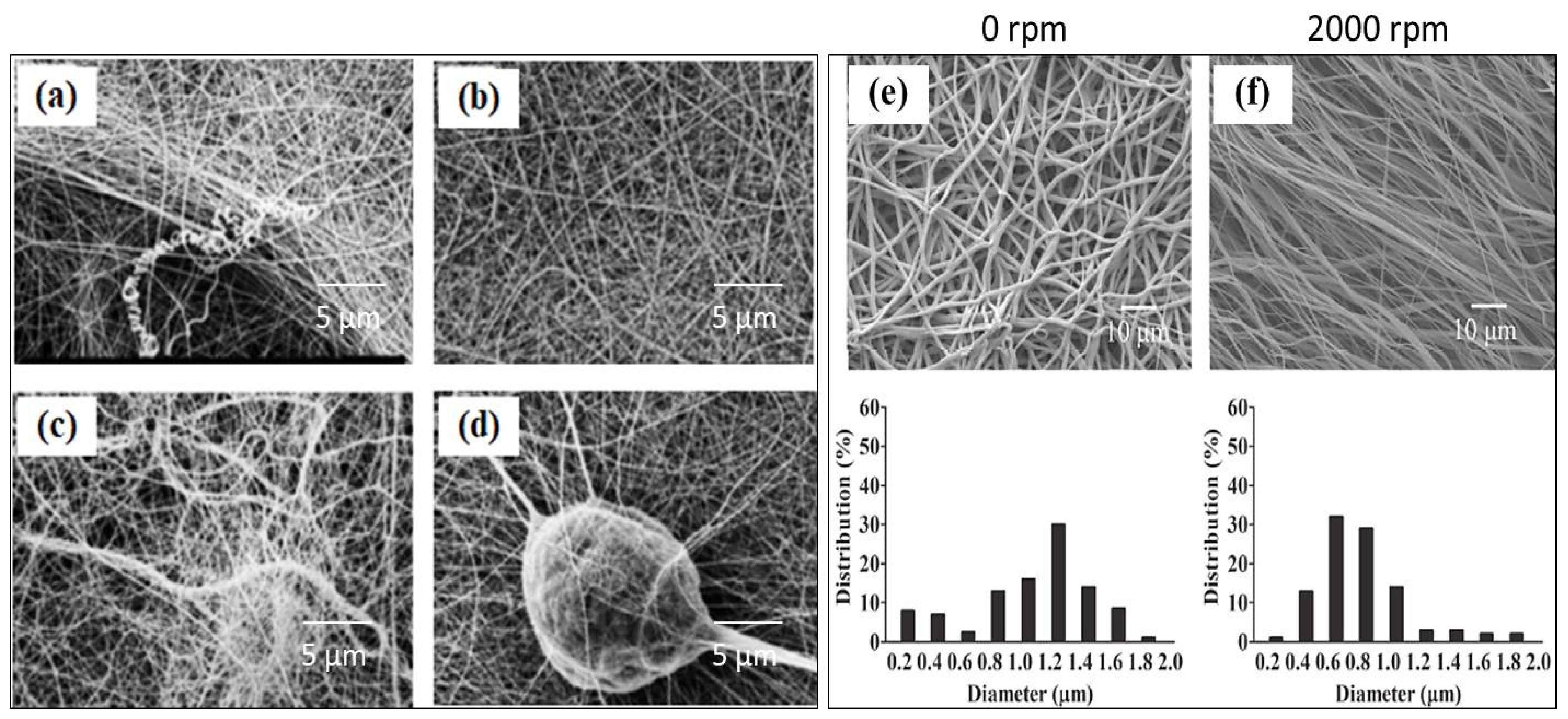
4.1.4. Collector Design and Drum Speed

In the electrospinning process, electrospun fibers necessitate a specific target for fiber accumulation, regarded as a collector. The design of a collector affects the structural morphology of the ultimate fibrous membranes. In normal situations, two basic types of collectors, i.e., stationary flat collectors and rotary drum collectors, are frequently employed at laboratory scales. The membrane formed on a flat collector consists of a smaller perimeter, unless the nozzle moves to and fro to a broader area. Also, the electrostatic forces exerted on fibers cause them to stretch the fibers. On the other hand, a rotary drum collector is more convenient for creating bigger nanofiber membranes since the drum can turn around its axis at a variable speed. Its velocity elongates the fibers, consequently aligning them and reducing their diameters. During rotational movement, electrostatic forces pull fibers parallel to their axis, while fused fibers are also created transversely by high rotational velocity. By choosing a particular collector design, one can examine the morphology of the resultant membrane to obtain distinctive features for specific applications [116,117].
Figure 6e,f show SEM micrographs of PCL nanofibers spun at different drum collector speeds. For a static collector drum (0 rpm), randomly oriented fibers were generated with a diameter of 1142 ± 391 nm. Upon increasing the rotational speed of the drum collector to 2000 rpm, most of the nanofibers became aligned, and a noteworthy decrease in the fiber diameter of 663 ± 334 nm was observed. The outcome might have been typified by the stretching force applied by the high speed of the drum during the deposition of fibers on the collector. Therefore, the graph plotted showed a narrower fiber diameter distribution (%). The muddled movement of the charged jets in the electrostatic field and the aerodynamic drag forces created by high-speed drum eventually impeded the formation of exactly aligned structures of nanofibers [112].
Kashif et al. [118] produced nanofibers using a polylactic acid (PLA) solution and a drum collector, varying the drum speed while keeping all other parameters constant. The drum speeds were set at 0, 300, 800, and 1300 rpm, resulting in different fiber alignment morphologies categorized as random, less aligned, medium aligned, and highly aligned, respectively. The results indicated that as the drum speed increased, the alignment of the nanofibers improved, while their diameter decreased. This demonstrated that the orientation of electrospun nanofibers could be controlled by adjusting the rotational speed (surface velocity) of the drum collector. Figure 7a–d present SEM micrographs of the samples, along with corresponding histograms (Figure 7e–h) and a graphical representation of the degree of fiber alignment, which consistently increased with higher drum speeds (Figure 7i–l). All samples were spun under identical conditions, with a weight per unit area (Wt/A) of approximately 0.0020 g/cm2. However, the layer thickness varied slightly, measuring 85, 80, 70, and 65 μm for drum speeds of 0, 300, 800, and 1300 rpm, respectively. This variation in fiber diameter is likely due to the different stretching forces applied to the emerging fibers, attributed to the variable rotational speeds of the drum collector.

4.2. Material Considerations

4.2.1. Solution Concentration

Solution parameters are crucial elements in the fiber formation process during manufacturing. The polymer concentration is essential for achieving smooth fibers with regulated diameters, as it varies from low to high concentrations. In electrospinning, the concentration of the polymeric solution is vital to obtaining the required characteristics. In this regard, PAN fibers were produced from different PAN solution concentrations. It was noted that as the PAN concentration increased, both the fiber diameter and electrical conductivity also rose [119]. Unverzagt et al. [120] investigated Poly (ethylene-co-vinyl acetate) (PEVA) using different PEVA materials with increasing vinyl acetate content. PEVA is a thermoplastic copolymer consisting of random ethylene and vinyl acetate (VA) monomers that can be spun using electrospinning. The polymer concentration was taken in a range of 4–16 wt%. An increased polymer concentration generally resulted in bead-free, beaded, or no fiber formation (Figure 8). For all samples, the parameters were adjusted as an applied voltage of 12 kV, a solution flow rate of 2 mL/h, and a collector-to-tip distance of 15 cm, which were used to observe the spinnability.
The data presented in Figure 8 indicate that the vinyl acetate (VA) content in PEVA, the molecular weight, and the polymer concentration are not consistent indicators of PEVA’s spinnability for creating bead-free fibers. For instance, Elvax240A (28% VA, 54 kDa) produced high-quality fibers from a 10 wt% solution, while PolyS28 (27% VA, 129 kDa) required a 16 wt% solution, which seems contradictory when viewed. Similarly, both Elvax40W (39% VA, 59 kDa) and PolyS40 (38% VA, 77 kDa) enabled the formation of bead-free fibers when a 16 wt% solution was used. The average fiber diameter ranged from 8.9 to 10.6 μm, irrespective of the polymer employed.

4.2.2. Polymer Molecular Weight

The molecular weight of a polymer significantly influences the diameter and morphology of electrospun fibers. Higher molecular weight polymers tend to produce fibers with larger diameters, while lower molecular weight polymers yield fibers with smaller diameters. A study was conducted using polycaprolactone (PCL) with three distinct molecular weights: Mw = 14,000 g·mol−1, Mw = 45,000 g·mol−1, and Mw = 80,000 g·mol−1. The results indicated that PCL with a high molecular weight (Mw = 80,000 g·mol−1) was suitable for producing micro-sized fibers, whereas PCL with a medium molecular weight (Mw = 45,000 g·mol−1) was ideal for generating a higher number of nano-sized fibers. On the other hand, PCL with a low molecular weight (Mw = 14,000 g·mol−1) was found to be unsuitable for creating micro- or nano-sized fibers via electrospinning, as it tended to form beads due to inadequate intermolecular interactions [121].
By carefully selecting the appropriate molecular weight, it is possible to produce micro- or nano-sized fibers with optimal morphology tailored to the specific needs of various applications. Perez-Puyana et al. [122] investigated a binary system of low-molecular-weight polymers, revealing that both the polymer concentration and the ratio of the two polymers in the system significantly affected fiber formation. Their initial findings suggested that phase separation may have occurred in certain polymer systems as their concentration increased during electrospinning, resulting in insufficient chain entanglement and reduced fiber uniformity. For PCL and gelatin, the most effective ratios were identified as 16:4, 20:4, and 24:4. This binary solution approach provides the right method for spinning low-molecular-weight polymers, which is often more economical. Additionally, by adjusting the PCL–gelatin ratio, membranes with customizable morphology, structure, and properties can be achieved.

4.2.3. Solution Viscosity

In general, a solution or melt must possess an appropriate viscosity to ensure the effective spinning of fibers. The viscosity of the solution must be sufficiently high to prevent the jet from breaking into droplets. However, excessively high viscosity can hinder jet elongation, reduce the attenuation of electrical charges, and even cause syringe clogging, all of which can impede fiber formation. On the other hand, a higher viscosity can lead to larger bead sizes and increased fiber diameters. Previous research suggests that a viscosity range of 1–20 poise is generally suitable for electrospinning. However, the values can vary depending on the type and composition of the polymeric solution or melt, as well as the intended properties and applications of the nanofibers. Shear-thinning fluids offer several advantages: (1) they enable the production of thinner and more uniform fibers, as their viscosity decreases when the jet is stretched by the electric field, reducing the jet diameter and facilitating fiber solidification; (2) they allow for higher fiber yield with lower energy consumption, as a decrease in apparent viscosity increases the flow rate, boosting material output while minimizing heat generation and solvent evaporation; and (3) they enhance the spinnability and stability of the jet, as reduced viscosity increases the electric field’s effectiveness, preventing the jet from breaking into droplets [123,124].
The viscosity of a dilute solution depends on its molecular size, which is distinct from its molecular weight. For instance, two macromolecules with the same molecular weight (M) can differ in structure, with one being linear and the other branched. These variations in size and shape lead to different intrinsic viscosities ([η]) and, consequently, different molecular weight values. The relationship between the intrinsic viscosity of a polymer solution and its molecular weight (M) is described by the Mark–Houwink–Sakurada equation.
[η] = k Ma
where [η] is intrinsic viscosity (units typically in dL/g), K is the Mark–Houwink constant, which depends on the polymer–solvent system and temperature, M is the average molecular weight, and α is the Mark–Houwink exponent, which reflects the polymer’s molecular structure and its interaction with the solvent.
The Mark–Houwink–Sakurada equation is critical for characterizing polymers because it helps determine their molecular weight through viscometry. Here, we add the following information:
If α = 0.5, the polymer behaves like a random coil in a theta solvent.
When α = 0.8–1.0, stiff or rod-like polymers are in a good solvent.
The values of “k” and “a” depend on the polymer–solvent pair and on temperature as well. Typically, the values of “a” are between 0.5 and 1. Choosing the optimal polymeric concentration enhances the viscosity relatively, and vice versa [125].

4.2.4. Solution Conductivity

The conductivity of a solution is determined by factors such as the type of polymer, the solvent used, and the presence of ionic salts, which can influence the final properties of the fibers. Higher conductivity generally leads to smaller fibers, whereas lower conductivity results in larger fibers. The selection of a solvent plays a crucial role in determining the physical and electrical properties of the solution, which, in turn, impact the structural morphology of the electrospun nanofibers. Therefore, selecting an appropriate solvent is essential for producing smooth, bead-free fibers. Various contributing factors regarding the solvent must be considered, such as its ability to dissolve the polymer to form a homogeneous solution, moderate volatility, and melting temperature. Solvents that are too volatile may evaporate during the movement of nanofibers from the needle tip to the collector, possibly disrupting the electrospinning process. Likewise, non-volatile solvents should be avoided, as they can prevent nanofibers from drying entirely upon reaching the collector, resulting in beaded structures. Research indicates that using a binary or combination of solvents can also significantly influence the nanofiber morphology. Phase separation may occur when one of the solvents acts as a non-solvent, which can cause the porous structures [126].
Javed et al. [127] electrospun graphene-based biopolymer nanofibers using an ionic liquid. Cellulose acetate (CA) was employed as the biopolymer, graphene oxide (GO) nanoparticles as the basis of graphene, and 1-butyl-3-methylimidazolium chloride ([BMIM]Cl) as the ionic liquid (IL) to produce CA-[BMIM]Cl-GO nanofibers via electrospinning. The combination of these bio-polymeric materials provided a homogeneous dispersion of GO nanoparticles. The slight addition of 0.43% graphene oxide significantly increased the conductivity value from 2.71 × 10⁻⁷ to 5.30 × 10⁻³ S/cm. This method for producing bio-based, ultrathin, lightweight, and flexible nanofibers can pave the way to develop an ecological material for smart electronic devices.

4.2.5. Surface Tension and Solvent Function

The surface tension and viscoelastic characteristics of a polymer solution are critical factors in electrospinning. Selecting a required solvent system of a specific polymer is the central component of an optimized electrospinning process. The selection of a solvent and its concentration is a crucial aspect of constructing the optimal morphology of nanofibers. If the polymer solution is too diluted, the polymer jet may split into droplets before deposition on the collector, resulting in no fiber formation. Conversely, a highly concentrated solution can hinder fiber formation due to its high viscosity, making it hard to control the flow rate through the tubes and needles. Generally, a spinning solution with a viscosity between 1 and 20 poise and a surface tension ranging from 35 to 55 dyn/cm2 is supposed to be suitable for electrospinning. When the viscosity exceeds 20 poise, electrospinning is hindered due to the instability in polymer flow caused by the solution’s high cohesion. As the viscosity of the solution increases, the polymer beads become larger, the average spacing between them increases, and the diameter of the resulting fibers also enlarges. Bead formation occurs when the fluid flow splits into droplets if the viscosity of the spinning solution falls below 1 poise.
Besides the solvent, the voltage also contributes to creating surface tension. When the applied electric field reaches a critical threshold value, it overcomes the surface tension of the droplet and eventually initiates the emergence of fibers. In the absence of an electric field, the surface tension of the liquid holds the polymeric solution at the tip of the capillary. When an electric field is applied, the polymer jet forms as the electric forces surpass the surface tension. A reduction in the surface tension can lead to instability in the jet, increasing the likelihood of the extruded filament breaking and forming droplets. Additionally, incorporating a surfactant into the solution can help lower the surface tension and promote greater fiber uniformity. However, it is essential to note that a lower surface tension does not always guarantee suitability for electrospinning [100,128,129,130].

4.3. Environmental Considerations

Besides the operational and material considerations, the environmental concerns cannot be neglected. During electrospinning, the physical characteristics of the fibers are greatly affected by the temperature and humidity of the surroundings because of their effect on solvent evaporation and the polymeric solution’s hygroscopic nature. The outcomes may vary in morphology, including the ability to form fibers, fiber size, beads or even fibers, and porous and flat fibers. These are directly associated with the temperature and relative humidity of the particular environment.

4.3.1. Relative Humidity

The structural morphologies of the ultimate fiber depend on the ambient relative humidity (RH %). In a normal room atmosphere, the air mostly consists of water vapors, nitrogen, oxygen, and carbon dioxide. Such molecules may interact or react with the processed materials during electrospinning. Relative humidity is a key parameter that significantly impacts nearly all properties of the resulting fibers, including diameter, morphology, tensile strength, liquid retention, wetting behavior, phase transitions, polymer chain conformation, surface potential, and more [131,132]. The effect of humidity directly influences the diameter of the resultant fiber because of the interaction between the polymeric solution and the ambient water vapors.
Karimi et al. studied polystyrene (PS) fibers and found that with a high percentage of relative humidity, fibers with larger diameters were spun from the identical solution concentration. Similar findings were also observed by Lcoglu et al. using polyetherimide (PEI) [133]. Another group studied the leading mechanisms for fiber generation at different humidity levels. They chose three commonly used polymeric materials of various physical properties, including polyethylene glycol, polycaprolactone, and polycarbonate urethane, which were electrospun with a relative humidity range from 5 to 75%. The results revealed that fiber breakage occurred for all polymer samples performed at low humidity levels (<50%). However, the effects at high humidity levels (>50%) depended on the polymer’s hygroscopic behavior, as well as the miscibility and volatility of the solvent with water [134].

4.3.2. Temperature

Among all other factors, temperature is the influential ambient parameter that plays an essential role in deciding the eventual morphology of fibers. The temperature change initiates two major and opposite outcomes: making the fiber thicker or thinner and altering the mean fiber diameter. The nanofibers’ properties were studied by the effect of temperature using cellulose acetate (CA) and polyvinyl pyrrolidone (PVP) materials. The results indicated that two main parameters, i.e., solvent evaporation and solution viscosity, were temperature-dependent and vitally affected the mean fiber diameter. Additionally, the outcomes suggested that as the environmental temperature increased, the rate of solvent evaporation also rose, while the viscosity of the polymer solution decreased relatively [135].
Some water-soluble polymer materials, i.e., PVP, PVA, and PEO, are influenced by temperature, which impacts the viscosity of their solutions, thereby improving polymer solubility and accelerating the rate of solvent evaporation. This results in a faster process that may end prematurely, leading to a larger fiber diameter [132]. In a research study, PLA electrospun nanofibers were spun as a function of collector temperature. The SEM images are shown in Figure 9. As shown in Figure 9a, numerous small pores were observed on the fiber surfaces at room temperature (21 °C). When the collector was heated to 40 °C (Figure 9b), the pore size increased. This effect is attributed to the boiling point of the solvent, methylene chloride (MC), used in the electrospinning solution. During electrospinning, most of the solvent evaporates, but some residual solvent remains trapped within the fibers. Heating the collector to a temperature near the solvent’s boiling point causes this trapped solvent to evaporate rapidly, resulting in the formation of larger pores due to accelerated solvent evaporation.
A distinct change in the shape and size of pores in PLA nanofibers was seen when the collector temperature was raised to 50 °C, as shown in Figure 10c. This change was linked to the rapid evaporation of the MC solvent at temperatures exceeding its boiling point. When the collector temperature was further increased to 60 °C (Figure 9d), the pore size decreased. At this stage, the solvent vapors trapped within the melt were released abruptly, and the accelerated evaporation of MC led to the formation of numerous small pores. Additionally, as the collector temperature approached the glass transition temperature (Tg) of PLA, the pore structures on the fiber surface began to collapse due to insufficient solidification. Figure 10e illustrates the pores formed when the collector temperature reached 70 °C (above PLA’s Tg). This behavior suggests that, in addition to collector temperature, the shape and size of pores are significantly influenced by the solvent’s boiling point and the polymer’s Tg [136].

5. Electrospun Nanofibers in Energy Storage Applications

The use of energy storage applications is increasing rapidly due to the fast expansion of electric vehicles. Such huge utilization provoked the study of high-performance storage devices. In such a context, nanofibers are widely utilized in energy storage devices because of their increased surface area and porosity. The unique structural morphology of these nanofibers is of great importance for functional materials and has been widely considered as the elemental ingredient. Many efforts have been made to produce nanostructured materials synthesized by multiple techniques. Among these, electrospinning is a more efficient and low-cost method utilized extensively to create numerous unique nanofibers with diverse morphologies [5,139,140].
In the realm of energy storage applications, electrospun nanofibers are extensively used as electrodes in LIBs, sodium-ion batteries (SIBs), lithium–oxygen batteries (Li-O2), redox flow batteries, and supercapacitors. The influences of their structural morphologies, along with their properties, on nanofibers are summarized in this section.

5.1. Application of Electrospun Nanofibers in Lithium-Based Batteries

Lithium-based systems comprise three fundamental types of battery systems, i.e., Li-ion batteries, lithium–sulfur batteries, and lithium–oxygen batteries, as shown in Figure 10a–c. As a key energy storage technology, lithium-ion batteries are widely used in portable electronic devices and have recently gained significant importance in power battery applications as a means of transportation. The use of nanomaterials in lithium-based battery systems contributes greatly to the commercial energy sectors [137].
Typical LIBs mainly comprise graphite-based anodes. The cathode is generally layered LiCoO2 and works as an intercalation host for Li+, which is separated by a polymeric porous fibrous membrane and dipped in an electrolyte, thus preventing a short circuit. LiCoO2 was initiated as a good-quality intercalated cathode used as an anode material in the 1980s. Later on, it was commercialized in 1991 by Sony Company. During the charging process, Li-ions de-intercalate from the lithium metal oxide in the cathode, surpass the electrolyte, and directly intercalate into the graphite anode. Electrons travel through the external circuit and recombine with the positively charged lithium ions (Li⁺) in the electrode, as shown in Figure 10d. Similarly, the reversal mechanism occurs during discharging (Figure 10e). Lithium-ion and electron generation can be explained by expression (3) [141,142].
At the cathode: LiCoO2 ↔ LixCoO2 + xLi+ + xe
At the anode: 6C + xLi+ + xe ↔ LixC6
Polymeric nanofibers can also be used as gel electrolytes after absorbing the electrolyte solution, which is attributed to their porous structure. Lithium-based batteries are considered the most preferential option in many electronic gadgets, i.e., laptops, computers, mobile phones, wearable devices, electric vehicles, electric storage reservoirs, etc. The four fundamental elements of a battery (anode, electrode, cathode electrode, electrolyte, and separator) determine the battery’s performance and safety. Lithium ions travel from the positive to the negative terminal during charging, wherein they are set into the porous electrode by intercalation. In contrast, Li-ions transmit the current from the negative to the positive terminal via a separator during the discharging process. Though LIBs present a capable solution to the universal energy crisis, several practical challenges must be addressed, particularly in devices that require high capacity. Enhancing the electrochemical efficiency and stability is one of these challenges. Various techniques have been used to boost performance, including coprecipitation, molten salt synthesis, pulsed laser deposition, and electrospinning. Utilizing a one-dimensional structure produced by electrospinning in LIBs offers a simplistic and cost-effective method. The continuous fibrous morphology of electrospun nanostructures can reduce the diffusion pathway for lithium ions, facilitating rapid lithium-ion transport [143,144].

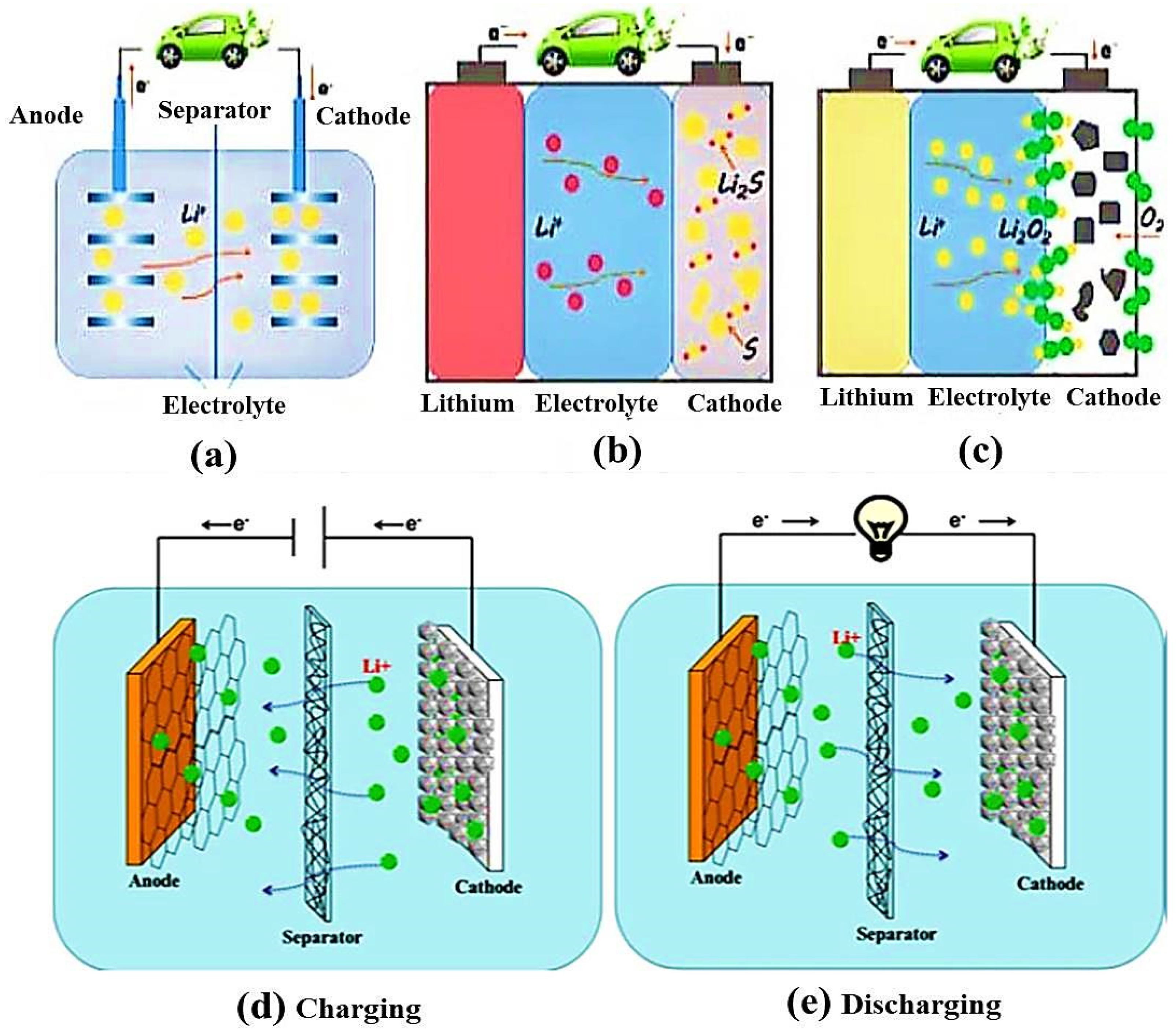
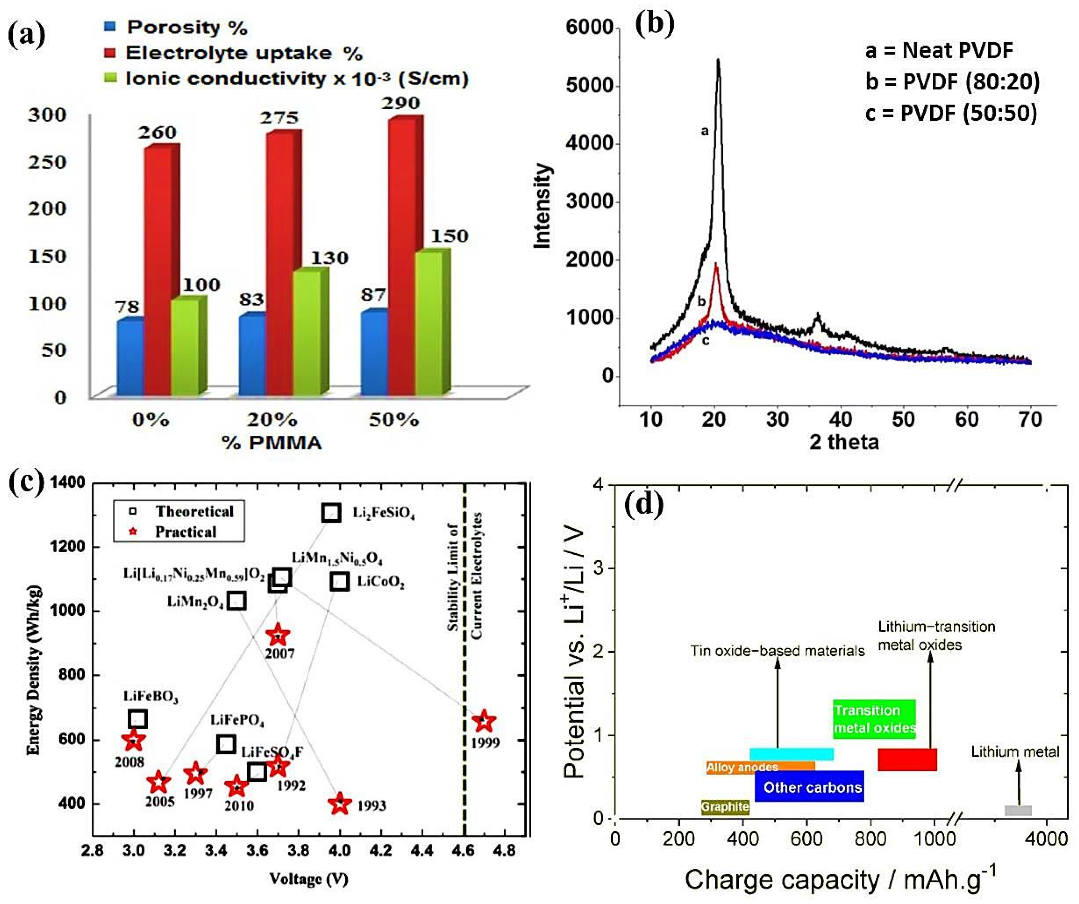
5.1.1. Electrospun Nanofibers as Separator Materials

A crucial part of electrochemical devices is the separator, which is positioned between the two electrodes. Principally, it avoids the hazard of short circuits in the system. For instance, lithium-ion batteries transfer lithium ions (Li+) between the electrodes during the charge–discharge. As the demand for lithium-based batteries grew, particularly for those offering high energy density and safety, a significant shift occurred toward creating lightweight and functional separators. This has led to the development of several innovative techniques for producing these separators, such as the phase inversion method and the melt-blown, wet-laid nonwoven, and electrospinning techniques [145]. The expansion of nanocomposite fibrous membranes has received significant attention due to the capability of the polymer matrix. Such proceedings assisted a lot in uniting the joint features of nanofibers and functional additives [146]. Though a separator does not make any contribution to the electrochemical process in LIBs, it acts as a barrier that performs a significant role by segregating both electrodes and allowing the open passage of lithium ions via electrolytes. Thus, the safety and the power performance of a battery are directly dependent on the separator [138].
So far, numerous separators have been developed, but polyolefin membrane separators have been the leading ones among all commercial lithium-ion systems because of their cost-effectiveness, excellent tensile properties, pore configuration, electrochemical constancy, and thermal shutdown function. Therefore, since 1970, several articles have been published on the two major polyolefin materials, i.e., polyethylene and polypropylene. On the contrary, along with their outstanding qualities, some problems exist regarding vehicular storage, such as non-polarity, low surface energy, and poor thermal stability. Therefore, these conventional commercial separators for LIBs may restrict the optimal performance of a battery [145,147].
Previously, the electrospinning of PVDF membrane-based separators for LIBs was reported, and the benefits of an electrochemical process were revealed. After annealing at high temperatures, the fibers soften and form an interconnected web-like structure. This type of structure significantly enhances the electrochemical efficiency. Porous fibrous membranes hold excellent electrochemical characteristics, such as greater ionic conductivity of 1.0 × 10⁻³ S/cm and broad electrochemical stability, reaching up to 4.5 V at room temperature. In addition, poly (vinylidene fluoride-co-hexafluoropropylene) (PVDF-HFP) composite membranes have high electrolyte uptake and ionic conductivities of 10−3 S/cm. However, these separators may have some drawbacks, such as weak thermal stability and an intrinsic hydrophobic nature [148]. The limited mechanical properties of electrospun PVDF fibrous membranes hinder their practical application, as they are inherently weak and unable to withstand the high tension generated during the winding process in battery assembly. However, heat treatment can enhance their mechanical properties [149].
In another study, nanocomposite fibers were spun by blending PVDF with poly methyl poly methylmethacrylate (PMMA) in variable PVDF: PMMA blend ratios of 100:0, 80:20, and 50:50. The polymer solution concentration was taken at 15 wt%. Due to the interconnected porous morphology, the resultant composite fibrous membrane revealed superb electrochemical properties. The histogram of neat PVDF, blended PVDF: PMMA 80:20, and 50:50 membrane separators concerning their electrolyte uptake, ionic conductivity, and porosity is shown in Figure 11a. The crystallinity (Xc %) values of all the samples were calculated using Equation (4):
Xc % = ΔHfHf * × 100
where ΔHf * indicates the melting enthalpy of completely crystalline PVDF, whose value was taken to be 105 J/g, while ΔHf is the melting enthalpy of the prepared electrospun neat and blended samples. Table 2 illustrates the electrochemical outcomes of all compositions. The highest crystallinity of the 50:50 blended membrane was 24.12% compared to 41.75% for the 80:20 blend and 50.75% for the 100% PVDF membrane. Therefore, the prepared 50:50 membrane sample had the lowest crystallinity, which signifies its amorphous nature as validated by XRD. The diffraction pattern indicated the effect of the PMMA content on the structure of PVDF in the sample, as shown in Figure 11b. The neat PVDF sample showed sharp peaks at scattering angles of 20.7° (110) and 26.60° (022), representing the orthorhombic α-phase [150]. These peaks were distinctly decreased in the blended samples. PVDF: PMMA (80:20) indicated a semi-crystalline nature, while PVDF: PMMA (50:50) signified its amorphous nature. As the PMMA content increased, the crystallinity of PVDF decreased significantly, with the 50:50 blend sample exhibiting a more amorphous structure. This enhanced amorphous nature ultimately improved the ionic conductivity of the polymer electrolyte across the membrane.
The 50:50 membrane’s lowest crystallinity value highlighted its potential to be used as a suitable separator for Li-ion batteries, as higher electrolyte uptake and ionic conductivity facilitate better lithium-ion transport. Increasing the PMMA ratio in the blend enhanced both electrolyte uptake and ionic conductivity in the PVDF: PMMA composite fibrous membranes. The findings suggest that electrospun 50:50 blend membranes are more promising as separators for Li-ion batteries compared to pure PVDF and 80:20 blend compositions.
In turn, advanced electrospun nanofiber-based separators have been developed, and extensive studies have been conducted in Li-S batteries [154,155,156]. A research team developed a multifunctional separator for Li-S batteries (NC-Co3O4/PANF), designed to adsorb and catalytically affect lithium polysulfides (LiPSs). This was achieved by incorporating polyhedral NC-Co3O4, derived from zeolitic imidazolate frameworks (ZIFs), into electrospun PAN nanofibers. The separators offer excellent electrolytic absorption/retention (335.13%), exceptional thermal stability (no changes up to 200 °C), and enhanced mechanical properties (8 MPa) [157].

5.1.2. Electrospun Nanofibers as Cathode Electrode Materials

Since the cathode electrode is the basic component of lithium ions, it is considered a crucial part of LIBs. It is cost-effective because the proportion of cathode material for LIBs is mainly produced. So, the good or bad working behavior of cathode materials chiefly determines the performance of lithium-ion batteries. Transition metal oxides (TMOs) are based on conversion reactions, which are attractive electrode materials for LIBs owing to their high theoretical capacity and safety features. Lithium transition metal oxides include LiCoO2, LiNiO2, LiMn2O4, LiMnO2, and LiFePO4, which provide high-performance cathode materials for LIBs. Specifically, LiCoO2 is one of the highly potential cathode materials for industrial applications. A nanofiber-decorated Li1.2 Mn0.54 Ni0.13 Co0.13O2 electrode revealed a higher value of CE 83.5% and a discharge capacity value of 263.7 mAhg−1 at 1 C, as well as high stability. The unique network structure provides a higher electrochemical performance, which gives rapid transport channels. The external carbon layer works as a shield that stops the internal oxides from reacting with hydrofluoric acid (HF) in the electrolyte during the process of charging and discharging [158,159]. The intercalation of cathode materials is usually categorized into three different types, i.e., layered, spinal, and olivine, based on their type of crystal lattice. An ideal cathode material should contain the following properties [160,161]:
i.
Great redox potential and enough storage of Li-ions to intercalate;
ii.
Rapid addition and taking of Li-ions;
iii.
Cost-effective, ecological, and easy to synthesize.
Figure 11c indicates the theoretical and practical evaluations of the gravimetric energy densities for various cathode materials. Although some materials, such as LiFeBO3 and LiFeSO4F, have approached their theoretical energy densities, others, including conventional layered and spinel compounds, still show significant gaps between their theoretical and practical energy densities. Materials with promising theoretical properties hold great potential as future candidates [152]. In addition to the gravimetric capacities of anode active materials, other factors, such as average voltage, porosity, and irreversible capacity loss, play a crucial role in determining anode performance. Typically, the primary active materials for anode electrodes include carbonaceous materials, alloys (Si, Sn, Al, Ga, Ge, Pb, and Sb), and metal oxides. Figure 11d illustrates a graphical representation of the voltage range versus Li/Li⁺ as a function of charge capacity for these anode materials.

5.1.3. Electrospun Nanofibers as Anode Electrode Materials

The fast propagation of mobile electronic devices and transportation demands the manufacturing of advanced LIBs. In this context, anode materials for LIBs are a potential candidate in determining the performance. Anode materials are classified as carbon and non-carbon. Graphite is used predominantly as an anode material commercially. The Li-ion battery anode material consists of Li+ reversible embedded layered formation. PAN and PVP are commonly used as precursors for carbon fibers, as their spun fibers can be carbonized to produce carbon nanofibers (CNFs) or carbon nanotubes (CNTs). Enhanced ion transport can be achieved by incorporating metal ions onto the surface of carbon fibers or embedding them within the hollow structures of carbon fibers, a technique widely applied in anode materials [141,144]. Besides carbon-based materials, electrospun metal oxides (Zno, Mno, Fe2O4, SnO) have also been widely investigated as anodes for rechargeable batteries [162,163,164]. In a recent study, high-entropy metal oxides (HEOs) were prepared by incorporating five metal ions into a single crystalline lattice. The porous hollow nanofibers of (NiCoCuFeMg)3O4 were spun by the electrospinning method. The Ni2+, Co2+, and Cu2+ ions contributed greatly to achieving a reversible capacity, while the Fe2+ ions played a vital role in improving the performance. The Mg2+ ions assisted in stabilizing the crystal structure. It exhibited a high reversible capacity of 907 mA h g−1, upholding nearly 100% of its initial capacity at a current density of 2 A/g after over 300 cycles. These results demonstrated excellent electrochemical and catalytic properties, indicating these materials as promising candidates for LIBs [165].
Recent interest in one-dimensional (1D) mesoporous nanofibers (NFs) has surged across various fields due to their unique mesoporous structure. However, traditional electrospinning, a widely used method for fabricating 1D nanostructures, is limited to producing solid NFs or those with a microporous structure rather than a mesoporous structure. A research group prepared mesoporous silicon electrospun nanofibers (m-SiNFs). These m-SiNFs displayed well-desirable electrochemical features that could be employed as anode material for LIBs. The study revealed a higher reversible ability of 2846.7 mAh g−1 with a current density of 0.1 A g−1. It also demonstrated a capacity of 89.4% at a 1 C rate (2 A g−1) for 100 cycles [166].

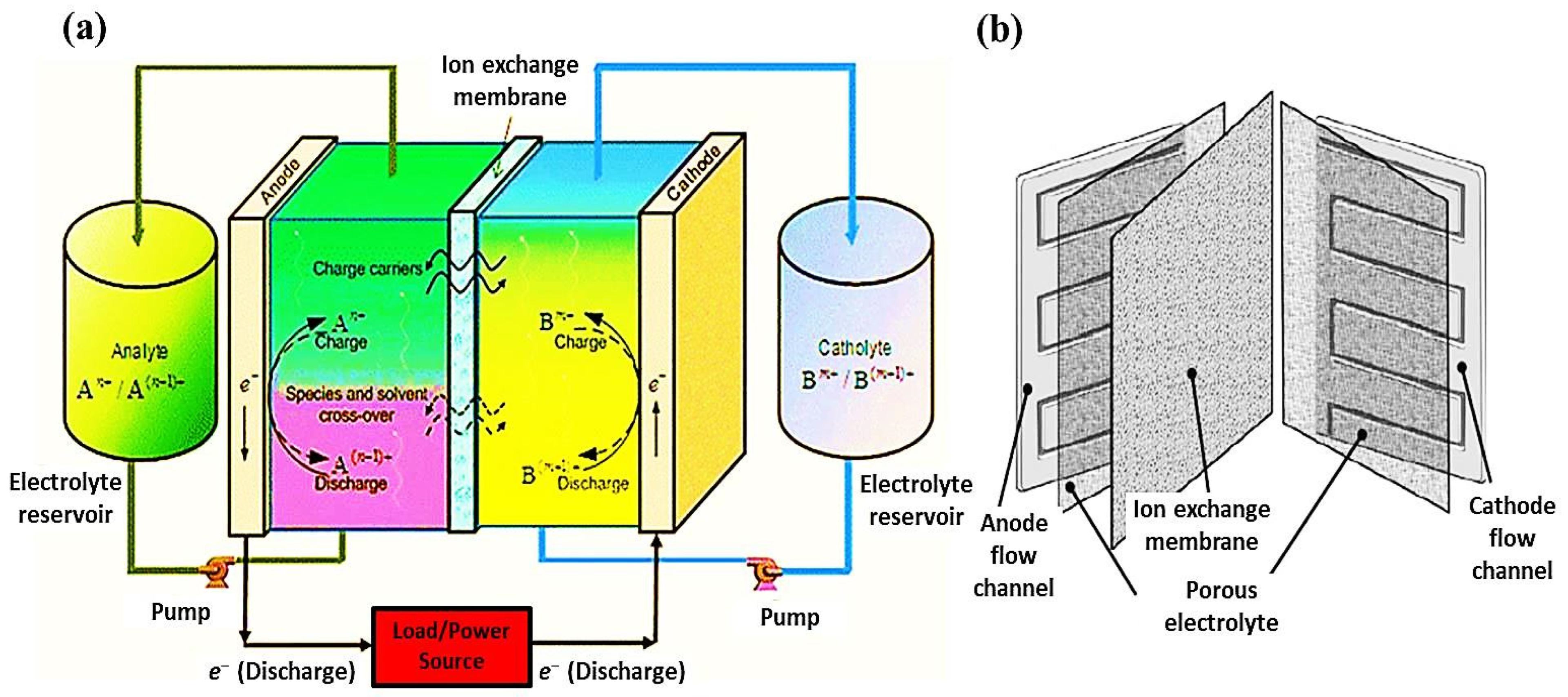
6. Electrospun Nanofibers in Redox Flow Batteries

A redox flow battery (RFB) is capable of storing large amounts of energy and converting electrochemical energy into electrical energy through reversible oxidation and reduction reactions between two liquid electrolyte solutions stored in external tanks. This idea was primarily considered in the 1970s. To obtain clean and prolonged energy from renewable resources, a well-organized, consistent, and cost-effective energy storage system is needed. Due to their flexible system design and scalable cost structure, RFBs are highly promising for stationary energy storage, like solar and wind. To enhance grid stability, energy storage systems are essential for storing excess electricity. This stored energy can then be supplied to end users or grid stations as needed. Rechargeable batteries based on redox flow chemistry offer a viable solution to address this challenge effectively [167,168]. Due to their expandable electrolyte storage chambers, RFBs are progressively considered a favorable solution for large-scale energy storage systems in various applications, such as backup power systems and surplus energy storage [169]. Comparing RFBs with other batteries demonstrates their promising characteristics, as shown in Table 3.
RFBs can be categorized as active species or solvents (aqueous and non-aqueous). During discharge, an anode solution runs in a porous electrode and then reacts to create the electrons that travel through the outer circuit. These reactions can be expressed by Equation (5) as follows:
For the anode electrode:
A n +   +   xe   charge   A ( n x ) +   and   A ( n x ) +   discharge   A n +   +   xe   ( n > x )
For the cathode electrode:
B m +     y e   charge   B ( m + y ) +   and   B ( m + y ) +   discharge   B m +     y e
The transportation mechanisms for the generic system of RFBs are demonstrated in Figure 12a. The basic component of these systems is the passage of these species through a separator, which is directly dependent on current flow and membrane permeability. Figure 12b shows a typical display of a cell arrangement. Single cells can be assembled in series to enhance the stack voltage. Usually, these stacks are positioned in a bipolar style. Consequently, the current runs in a series circuit from one to the adjacent cell [171].
Zhao et al. [172] fabricated a porous carbon fiber-based bundle electrode using PAN and polystyrene (PS) via electrospinning, as illustrated in Figure 13a. Numerous nanochannels in the carbon fibers increased the specific surface area significantly, hence enhancing the performance of the mass transfer of the electrode (Figure 13b). The formation of the fiber and fiber bundles regarding the low-viscosity and high-viscosity of electrospinning solutions is shown in Figure 13f,g, respectively. The current density of PAS 10 was approximately 2.6 times greater than that of PAS 0 at 200 mA cm2 (Figure 13h). The energy efficiencies of the PAS 10 electrode were also enhanced significantly, as shown in Figure 13i,j.

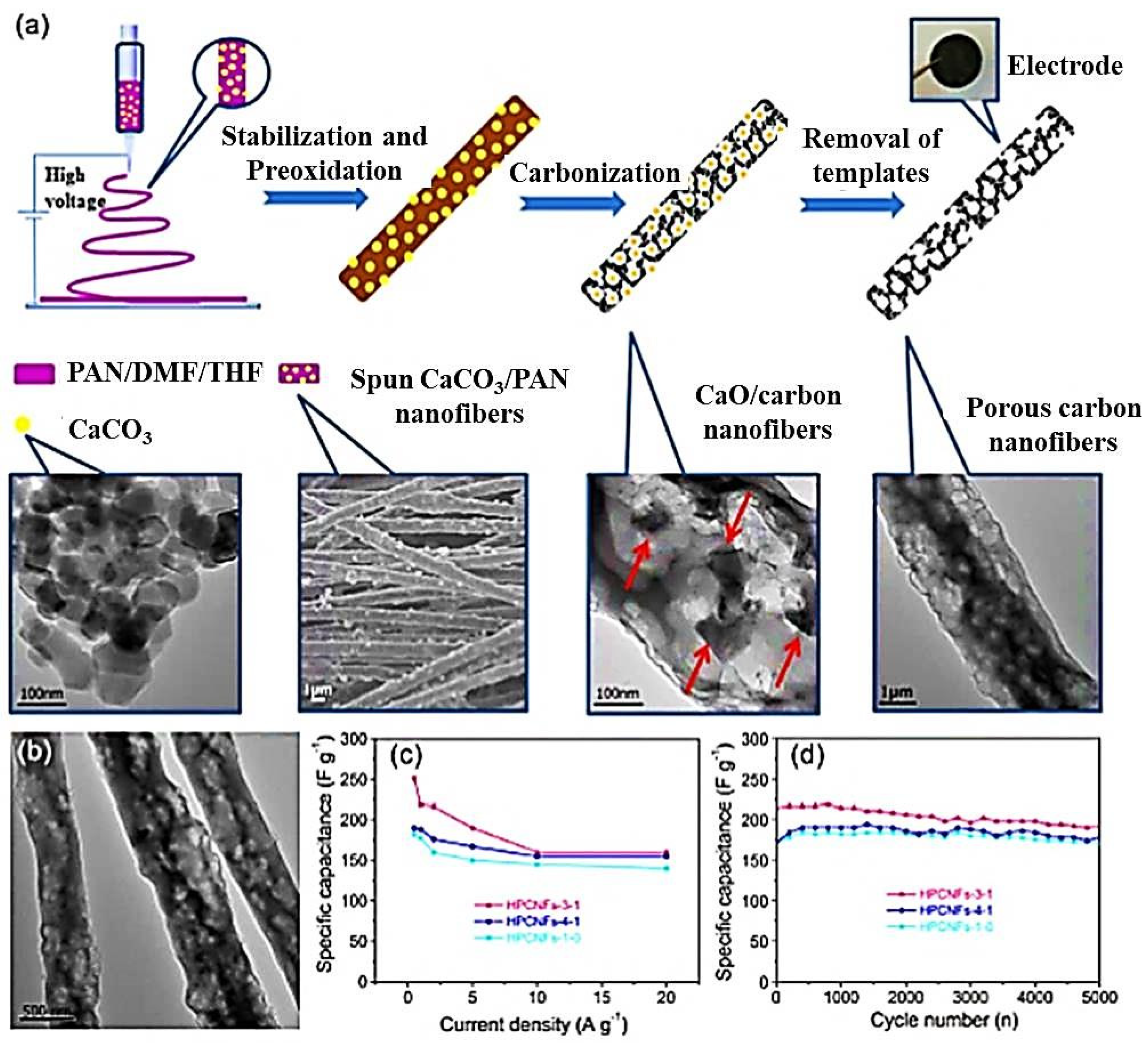
7. Electrospun Nanofibers in Supercapacitors

Supercapacitors are energy storage devices that operate electrochemically to store and deliver energy at higher rates with massive power density and a long cyclical life. Owing to their fast charge and discharge times and extended cyclic life, supercapacitors have received much attention in recent years. They have great potential to cover the energy gap between traditional capacitors and batteries. Electrospun nanofibers are produced by simplistic and cost-effective electrospinning techniques that show greater electrochemical performance in supercapacitors because of their unique structure and fascinating features, representing the huge potential to improve the performance of supercapacitors. Many advanced electrospun nanomaterials for supercapacitors have been developed, demonstrating outstanding electrochemical performance and structural stability. Due to their structural morphology, including greater surface area, high porosity, hydrophilicity, low density, texture, and tunable features, electrospun nanofibers are the best prospective candidates for various electrochemical energy storage devices [19,173]. Secondary batteries cannot accomplish the overall requirements for electrical energy storage; therefore, batteries are frequently coupled with the quick methods used in capacitors and supercapacitors to balance such situations. Predominantly, such devices are founded on the movement of electrons and ions. Capacitors and supercapacitors possess inferior energy density for storage; meanwhile, these devices allocate higher power rates per unit mass during charging and discharging. Such characteristics greatly facilitate energy recovery, for instance, in brake vehicles and elevators [174].
In terms of charge storage systems and the utilization of active materials, supercapacitors are usually classified into two basic types: electrochemical double-layer capacitors (EDLC) and pseudo-capacitors. EDLCs store electrical energy through the reversible adsorption of ions from an electrolyte solution onto two porous electrodes, creating an electric double layer at the electrode–electrolyte interface. Pseudo-capacitors differ from EDLCs in their charge storage mechanism, as they do not rely on the traditional charge separation process. Therefore, in general, pseudo-capacitors contain superior capacitance than EDLCs. Instead of usual carbon materials, electrospun nanofibers are employed as the electrodes of supercapacitors, which are dipped in an electrolyte [175,176].
Zhang et al. [177] incorporated CaCO3 nanoparticles into a polymeric solution using two-component solvents: dimethyl formamide (DMF) and tetrahydrofuran (THF). They acquired a one-dimensional CNF layer after using electrospinning, heat treatment, and hydrochloric acid (HCL) acidification. The preparation procedure and characterization are shown in Figure 14. The binary solvent used in the solution preparation favored the homogenous dispersion of CaCO3 in the composite nanofiber. At elevated temperatures, the carbonization process of the electrospun fibers occurred; the nano-CaCO3 thermally decomposed and released CO2 to produce micropores and mesopores on the surface of the fibers. The CaO nanoparticles were detached by acidification with hydrochloric acid (HCL), forming the macropores on the fiber’s surface. When this electrode material was used as an electrode material, it exhibited hierarchical porosity and high specific surface area, thus giving a high specific capacitance value of 251 F/G at a current density of 0.5 F/G [175,176,177,178].
The outcomes implied that the electrochemical performance of the electrode material prepared by pure polymer CNFs is not ideal since it has a low specific surface area and nearly no porous structure. Therefore, it is essential to improve its structure. The CNFs with porous structures produced by the template method have a highly specific surface area and rich pore structure. Such a trait increases electrode materials’ adsorption and storage capacity for electrolyte charges and improves ion transportation. Thus, it improves the specific capacitance and performance of the supercapacitors. Moreover, the voids in the porous electrospun CNFs can shield the change in the internal structure of the electrode material during the process of charging and discharging, yielding high cycle stability.

8. Other Electrospun Nanofiber-Based Energy Storage Devices

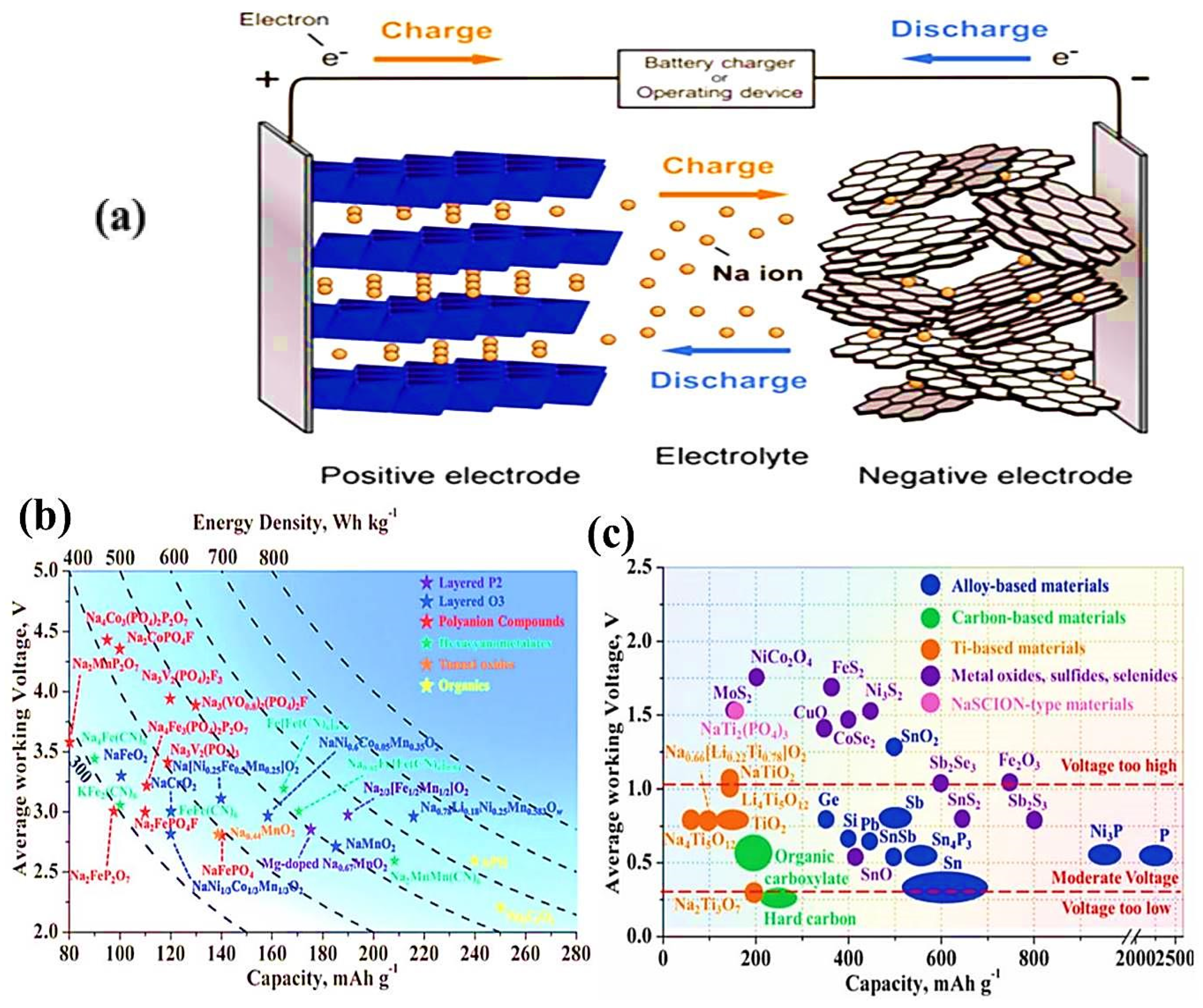
8.1. Sodium-Ion Batteries

Sodium metal is the most helpful option after lithium metal, as its physical and chemical properties are identical to lithium metal. Both batteries were discovered simultaneously in the 1980s. In that era, sodium was inconspicuous due to the more desirable characteristics of LIBs, specifically energy density. Due to the rapid demand for energy, it again became essential for researchers due to the low cost of raw materials. Moreover, the working mechanism of SIBs also resembles LIBs, which depend on Li+ transportation. It consists of two “Na”-immersed anode and cathode electrodes that are physically isolated by a polymeric membrane separator and also by an electrolyte [179].
Due to the plentiful availability, cost-effectiveness, and environmental provision of Na resources, SIBs are robustly considered, like LIBs, to be large-scale electric storage devices. However, the main challenge is finding suitable “Na” storage electrode materials that contain plentiful Na+ ions with sufficient capacity and diffusion kinetics. Concerning the cathode electrode, layered metal oxide (LiMnO2) has been employed for LIBs. So, in the same way, NaMO2 has been treated as a Na-intercalated electrode. As an essential part of SIBs, the cathode is supposed to be more involved in influencing the significant effect on the electrochemical efficiency of SIBs. The layered NaMO2 materials seem more suitable, as their compounds generally form an O3 structure.
Figure 15a shows a comparison of specific capacities, operating voltages, and energy densities of various cathode materials, which primarily include sodium metal oxides with layered and tunnel structures, as well as polyanion-based cathodes, such as pyrophosphates, phosphates, sodium superionic conductors (NASICON), and fluorophosphate. Graphite is broadly employed as an anode electrode material for LIBs, possessing high gravimetric and volumetric capacity because of rapid intercalation kinetics. In addition, the first basic calculations suggested that sodium (Na) faces greater difficulty in forming intercalated graphite compounds compared to other alkali metals. Numerous anode materials have been investigated, and their performances have been evaluated (Figure 15b). A wide range of materials, such as carbon-based compounds, titanium (Ti)-based materials, NASICON-type structures, alloy-based systems, and conversion reaction-based materials (including metal oxides, sulfides, and selenides), have been extensively studied. Among these, carbon-based materials, such as graphite and organic carboxylates, are still known as potential candidates for anodes because of their moderate operating voltage and relatively high specific capacities [180,181].
Owing to their intrinsic simple synthesis process, cost-effectiveness, and greater theoretical capacity, vanadium and vanadium-based materials (transition metal elements in valence states V2+, V3+, V4+, and V5+) are employed in electrochemical energy storage devices [146]. Luo et al. [183] synthesized Fe2VO4 hierarchical porous microparticles as an anode electrode for SIBs, which yielded a high capacity value of 229 mAh g−1 after 1000 cycles at 1 A g−1. When employed as an anode material for SIBs, it revealed a great reversible capacity of 668 mAh g−1 (after 50 cycles). After 6000 ultra-long cycles at 2 A g−1, it demonstrated a superb capacity value of 265 mAh g−1 (Figure 16a,b). Xu et al. [184] prepared a vanadium nitride/carbon fiber (VN/CNF) composite material using electrospinning followed by an ammoniation process (Figure 16b) [183,184].

8.2. Potassium-Ion Batteries

Potassium-ion batteries are more convenient because potassium elements, like the Na element, are abundant on Earth. PIBs are a promising next-generation technology for high-energy storage systems. They are cost-effective, made from readily available raw materials, and exhibit chemical similarities to lithium, making them a potential alternative for lithium-ion batteries. Additionally, PIBs could serve as a backup or complementary technology for lithium-ion battery systems [185,186].
Carbon-based materials are the most widespread among all PIB materials because of their cost-effectiveness and high thermal stability. Carbon nanofibers (CNFs) have been prepared using the electrospinning method, and the subsequent heat treatment has received great attention. Xu et al. prepared multichannel carbon fiber (MCCF) samples via electrospinning. The precursor solutions were created by blending varying proportions of PMMA with PAN (0%, 1%, 2%), followed by calcination treatment after the electrospinning process. The MCCF electrode demonstrated a remarkable reversible charge capacity of 420.1/304.2 mAh g−1 at a current density of 50 mA g−1. Additionally, it maintained a capacity of 110.9 mAh g−1 over 2000 cycles at a high current density of 2000 mA g−1. This exceptional electrochemical performance was due to the unique multichannel structure in amorphous MCCFs, which facilitated electrolyte permeation, and the high conductivity resulting from nitrogen (N) and oxygen (O) doping in the MCCFs. The unique design technique for multifunctional electrode materials provided a practical pathway for creating high-performance and cost-efficient materials suitable for alkali-ion batteries [187,188].
To investigate the multichannel structure of MCCFs, the Brunauer–Emmett–Teller (BET) surface areas and pore distributions were analyzed, as illustrated in Figure 17e,f. It was observed that the surface areas of BET of all the MCCF samples increased relatively with the increase in the PMMA content in the precursor solutions, signifying that PMMA played a vital role in producing channel spaces within the fibers. When comparing the mesoporous structures of MCCF-1 and MCCF-2, it was evident that the MCCF-2 sample primarily contained macropores, suggesting that the inner channel diameters in MCCF-2 were larger than those in MCCF-1, consistent with the SEM morphologies of both samples. Additionally, the structural characteristics of the MCCF samples were examined using XRD and Raman spectroscopy, as shown in Figure 17g,h, respectively. All samples exhibited a single weak and broad peak at a 2θ angle of 24°, related to the (002) plane, which confirmed the amorphous nature of the whole samples.
The electrochemical performance of the MCCF electrodes is shown in Figure 18. Figure 18a presents the cyclic voltammetry (CV) curves of the MCCF electrodes at a scan rate of 0.1 mV s−1 (five cycles). All CV curves show a noticeable reduction in the peak around 1.4 V during the first cycle, likely due to the formation of a solid electrolyte interface. The smooth peaks below 0.4 V correspond to the intercalation of K⁺ ions into the MCCFs. Similarly, the oxidation peaks at approximately 0.3 V and 0.7 V represent the extraction of K⁺ ions from the MCCF electrode. Figure 18c shows the cyclic performance. The irreversible capacities at the initial cycles are due to the higher specific surface area of MCCF-2. In contrast, after 50 cycles, an increase in Coulombic efficiency is observed to 90%, and the particular capacities decreased gradually after 100 cycles, showing excellent cycling stability. Regarding the performance of the MCCF-2 electrode, it had a high-performance rate, as shown in Figure 18d. Moreover, the long-term cycling performances were also analyzed after three cycles at a high current density value of 2000 mA g−1, as shown in Figure 18e. The MCCF-2 electrode revealed superb cycling stability with a reversible capacity of 110.9 mAh g−1 (2000 cycles) [189,190,191,192].

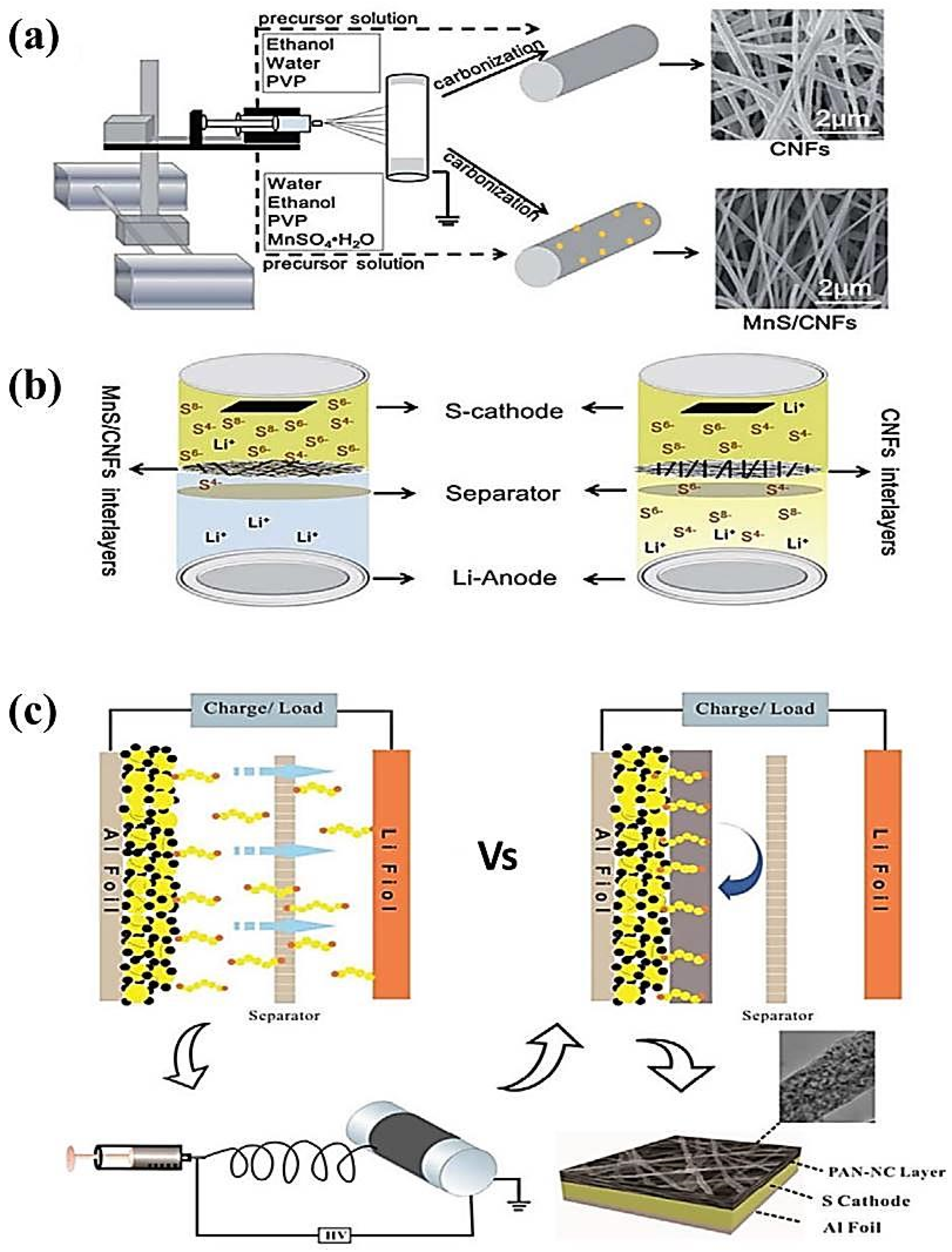
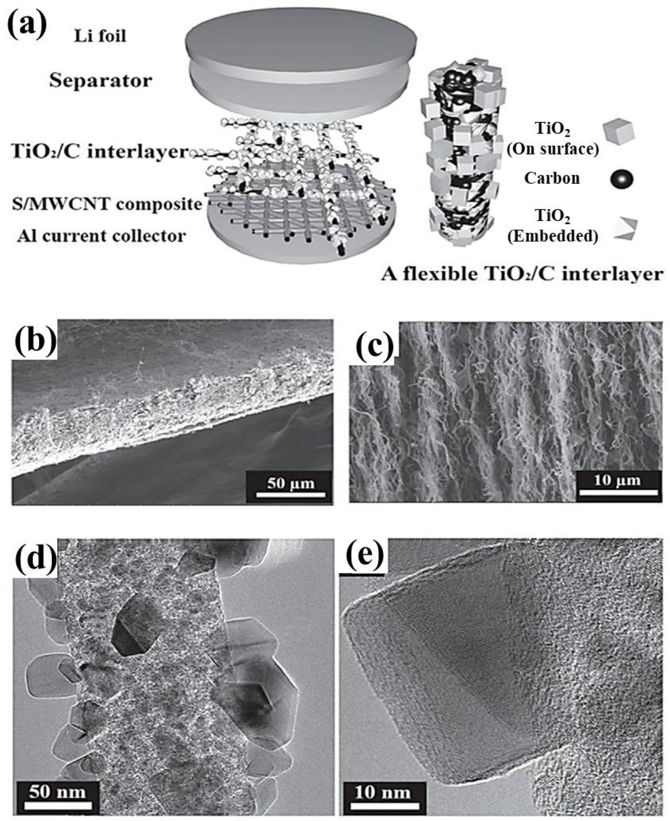
8.3. Lithium–Sulfur Batteries (Li-S)

Lithium–sulfur batteries are vital since their exceptional theoretical energy is much greater than commercially employed lithium-ion batteries. Regarding upcoming developments in the market of energy storage devices, Li–S batteries are the hard-hitting competitors. However, the rigorous “shuttle effect” of the poly sulfides and the severe harm of lithium dendrites are the main issues that prevent the commercial production of Li–S batteries. Due to their advanced nanostructure, electrospun nanofibers usually demonstrate distinctive features that can help resolve these issues.
Lithium–sulfur (Li–S) batteries, containing a high theoretical energy density, are recognized as one of the high-potential battery systems. Typically, they consist of a sulfur cathode, separator, electrolyte, and lithium anode. Moreover, the novel battery system comprises an additional interlayer [193,194]. Usually, Li reacts with sulfur (S8) to make lithium polysulfides of the formula Li2Sn. At first, extended chain polysulfides, such as Li2S8 and Li2S6, are created, which condense through sulfur reduction. On the whole, the reaction can be written as below [195].
16Li + S8   →   8Li2S
For Li–S batteries, elemental sulfur is usually exploited as a cathode material, amongst cyclo-S8. Typically, a sulfur electrode requires the ensuing features of a closed structure for effective polysulfide self-control and enough space to lodge the volumetric growth of sulfur [196]. When using nanofiber-based cathode materials, Li–S exhibits immense electrochemical performance, attributable to excellent characteristics such as excellent surface area and flexibility [197]. Li metal acts as an anode electrode in rechargeable Li–S batteries. The use of Li as an anode in Li–S batteries raises fundamental safety issues that arise from the generation of Li dendrites during cycling, which may go through the separator. Furthermore, the constant reaction of the soluble polysulfide with the Li anode leads to notable self-discharge along with the collection of hard Li2S2 and Li2S on the cathode, which results in the loss of inactive mass and reduces the capacity [198].
In terms of perspective, lithium–sulfur (Li–S) batteries have been widely studied. Though they are highly cost-effective and ecofriendly, the complex multiple steps of the electrochemical reaction and solid–liquid and liquid–solid phase change between S and Li2S have some drawbacks for their practical applications. Specifically, the poor conductivity of S and Li2S, the shuttle effect of polysulfides (LiPS), the slow movement of sulfur ions in the cathode, and the growth of lithium dendrites, which may cause high flammability of the separator, could also contribute to reduced cycle stability. Therefore, it is necessary to tackle these problems [199].
Wang et al. [200] reported MnS/CNFs nanofibers fabricated via the electrospinning method for the flexible interlayer for Li–S batteries, as demonstrated in Figure 19a,b. The MnS particles were evenly entrenched in the carbon nanofibers. Also, they created nanopores in the carbon fiber substrate. Moreover, Peng et al. [201] used a process of coating PAN and nitrogen-doped carbon fibers (PANNC) directly onto a neat sulfur cathode via electrospinning, as illustrated in Figure 19c. It is suitable for electrolyte infiltration and Li+ diffusion and can also buffer the volumetric expansion of the sulfur cathode. Thus, PAN-NC@Cathode reveals improved active materials, rate capability, and cycling stability, implying it as a promising candidate using the electrospinning interlayering approach.
Kumar et al. [202] stated that a praline-like flexible interlayer formation, which consisted of TiO2 nanoparticles and carbon nanofibers to avoid the shuttle effect in Li–S batteries, attained cycle stability and rate capability, as illustrated in Figure 20a–e. The carbon nanofibers enhanced the conductivity value of sulfur and Li2S; however, the weak interaction of LiPS and nonpolar carbon made it impossible to avoid the shuttle effect satisfactorily.

8.4. Lithium–Oxygen Batteries (Li-O2)/Li–Air Batteries (LABs):

Athough lithium-ion batteries are widely utilized, their theoretical energy density is nearing its upper limit. To drive further progress, it is crucial to explore alternative battery technologies with higher energy capacities. In this context, metal–oxygen batteries have attracted considerable interest due to their exceptionally high theoretical energy densities. Among these, lithium–oxygen (Li–O2) batteries stand out, boasting a high thermodynamic equilibrium potential (~2.96 V) and an improved theoretical specific energy of approximately 3500 Wh kg−1. These characteristics make Li–O2 batteries a promising option for next-generation energy storage systems [203,204]. A schematic illustration of Li–air batteries (LABs) is shown in Figure 15b.
Li–O2 reaction mechanisms always depend on the electrolyte used. Oxygen gas is employed as a cathode material. Therefore, porous carbon and catalyst composites should be appended as the Li2O2 reservoir in the cathode electrode [205]. The non-aqueous-based electrolyte system was initiated by Abraham et al., [206] who proposed the successive stepwise reaction mechanism as
2Li + O2 → Li2O2 E0 = 3.10 V vs. Li/Li+
4Li + O2 → 2Li2O E0 = 2.91 V vs. Li/Li+
The standard cell potentials (E0) were determined based on the standard Gibbs free energy of formation. After that, Bruce et al. suggested that Li2O2 originated upon charging and decomposing, corresponding to the reaction (Li2O2 → O2 + 2Li+ + 2e).
For the anode material, lithium metal is used because of its potential for high energy density, attributed to its strong electro-positivity (−3.04 V vs. standard hydrogen electrode) and lightweight nature (equivalent weight = 6.94 g mol−1, specific gravity = 0.53 g cm−3). It also offers a remarkable specific capacity of approximately 3860 Ah kg−1. However, using lithium metal with aqueous electrolytes poses challenges for rechargeable batteries because of its highly reactive nature with polar aprotic solvents. Additionally, the reaction between lithium metal and electrolyte components forms a solid electrolyte interface (SEI) on the anode surface during the initial charging cycles. The surface morphology of lithium deposition tends to be dendritic and porous, which can lead to the detachment of lithium layers from the anode substrate during discharging. This detached lithium layer causes anode material degradation, reducing the battery’s cycle life. Consequently, dendritic lithium growth and the instability of lithium metal electrodes present significant challenges that must be addressed to achieve optimal performance [207].
Several challenges exist, such as the gradual clogging of air cathode electrode pores in lithium–air batteries (LABs) by Li2O2 precipitates during discharge. Therefore, factors like pore size, electrode thickness, surface area, electrolyte wettability, and the electrical connectivity of active materials must be carefully considered when designing air electrodes for LABs [205,208,209]. Numerous studies have been conducted for the development of catalysts for lithium–air batteries (LABs), focusing on their mechanisms to enhance efficiency and durability for potential applications. For instance, Bruce et al. investigated the impact of various catalysts (La0.8Sr0.2MnO3, Fe2O3, NiO, Fe3O4, Co3O4, CuO, and CoFe2O4) with particle sizes ranging from 1 to 5 μm [210]. The ORR (oxygen reduction reaction) and OER (oxygen evolution reaction) could occur without a catalyst. Still, the catalysts could facilitate both reactions, whereas the catalysts somewhat changed the discharge voltage.
Bui, H.T. et al. [211] developed carbon nanofiber@platinum (CNF@Pt) via coaxial electrospinning and improved its electrochemical performance as a cathode. Figure 21a illustrates the schematic process for preparing CNF@metal membranes. These membranes were prepared by carbonizing core–shell nanofiber (NF) membranes. The electrospun core–shell nanofibers consisted of PAN (core layer) and PVP mixed with a metal precursor (shell layer). Following heat treatment, the core–shell nanofibers transformed into CNFs with metal nanoparticles dispersed on their surfaces. By using alumina plates during the thermal process, flexible and porous flat membranes were acquired.
Figure 21b,c demonstrate the SEM and TEM images of the electrospun core–shell nanofibers, consisting of PAN, acting as a core layer, and PVP with the Pt precursor Pt(AcAc)2, acting as a shell layer. The electrospun nanofibers show straight, fallacious morphology with even fiber diameters (Figure 21b). The contrast in the TEM image (Figure 21c) indicates the nanofibers’ core–shell structural morphology. The core NF diameter was noted at about 390 nm, and the thickness of the shell layer was measured at 165 nm, resulting in a core–shell NF diameter of around 720 nm. Figure 21d,e show the SEM and TEM images for CNF@Pt, respectively. The structural morphology of the nanofibers was somewhat crumpled and revealed decreased diameters of about 300 nm of CNF@Pt after providing heat treatment. The effect was attributed to the burning of the PVP in carbonized NF in the shell layer, which caused little shrinkage when the PAN in the core layer was changed to carbon [212]. The thermal treatment also decomposed Pt(AcAc)2 and produced Pt nanoparticles at the surface of the CNFs, as shown in Figure 21e. These nanoparticles were also observed as Pt by XRD, as illustrated in Figure 21f. In addition, the carbon structure and electronic characteristics of CNF@Pt were investigated by Raman spectroscopy, as described in Figure 21g. The Raman spectra of the CNF and CNF@Pt show characteristic D- and G-bands at around 1340–1350 and 1580–1590 cm−1, respectively. The G-band intensity in CNF@Pt increased dominantly in comparison to the CNF, signifying that Pt nanoparticles enhance the degree of graphitization of CNFs [213].
Figure 22a–c illustrate the Galvano-static full discharge-charge profiles for the initial cycle of Li-O2 cells by using the CNF and CNF@Pt cathodes at the variable current densities of 200, 500, and 1000 mA/gc. Though, the whole discharge-charge profiles of the Li–O2 cells were alike but the specific capacities of the cells using the CNF@Pt sample were much greater than those of the cells using the CNF sample. Concerning the CNFs, the specific capacities of the cells at 200, 500, and 1000 mA/gc were found 4079, 3369, and 1533 mAh/gc, respectively. While for the CNF@Pt, these were 6938, 5781, and 5133 mAh/gc. Moreover, the over-potentials in the CNF@Pt on both the discharge and charge were found to be much lower than those in the CNF.
To study the nucleation and morphology of the primary discharge product, Li2O2, during cycling, SEM analysis was conducted. Figure 22e–g and Figure 22h–l display SEM images of the CNF and CNF@Pt samples, respectively, at various discharge–charge stages, as marked by the dots in Figure 22a. The results revealed distinct nucleation patterns and morphologies of Li2O2 for both cathodes. For CNFs, small toroidal Li2O2 particles (approximately 250 nm in diameter) fully covered the surface when the cell was discharged to a capacity of 1000 mAh/gc. As the discharge process continued, the size of Li2O2 particles grew to around 700 nm (Figure 22a,b). In contrast, for CNF@Pt, toroidal Li2O2 particles with diameters of 400–500 nm were observed on the surface at a discharge capacity of 1000 mAh/gc (Figure 22h). With further discharge, the Li2O2 particles expanded to 1.3 μm in diameter, leaving the fiber surfaces partially exposed (Figure 22e,f). The cycling performance of the Pt-catalyzed Li–O2 cell was primarily driven by the reversible formation and decomposition of Li2O2, as evidenced by significant O2 release and minimal CO2 production, even after extended cycles.

9. Challenges and Perspectives

At present, research in the energy sector is encountering significant challenges in air pollution, climate change, and the depletion of fossil fuel resources, particularly the performance and durability of essential materials. Therefore, functional materials are needed to address these concerns. Energy storage devices are recognized for their growing importance as a primary power source for many practical applications, such as electric vehicles, portable electronics, and power tools. So far, many materials have been employed in these applications, such as advanced anodes, cathode electrodes, and separator materials. However, the materials used may have unique characteristics; it is widely agreed that innovative, affordable, and psychodynamic materials with specially designed nanostructures are crucial for significant advancements in the energy sectors. In this context, electrospun nanofibers are a building block for many energy storage devices. The electrospinning technique serves as a highly effective and adaptable method for the production of nanofibers, characterized by a significant surface-to-volume ratio, high porosity, and customizable structures, apt for large-scale manufacturing across various applications, particularly in electrochemical energy storage and conversion devices, e.g., lithium-ion batteries, sodium-ion batteries, potassium-ion batteries, lithium–sulfur batteries, lithium–air batteries, and supercapacitors. Some advanced nanomaterials, such as graphene, carbon nanotubes (CNTs), and polymeric nanofibers, are vital in addressing the critical challenges in technological innovations and practical applications.
Electrospinning is a fascinating technology that emerged in the early 1900s. It is known for its ability to create fibers of tunable structures with large specific surface areas. This capability has made it worthwhile in various energy component materials. Over the past decades, there has been significant progress in this field. Researchers have been working hard to understand the mechanisms behind improved electrospinning and to enhance the performance of electrospun nanofibers in energy applications. As a result, materials produced through electrospinning have improved capacity, efficiency, and lifespan. Nonetheless, electrospinning presents exciting opportunities for creating complex networks of nanofibers that can enhance efficiency; however, there are still several challenges to address regarding the preparation of nanofiber electrodes.
Over the last decade, extensive research has shown that understanding their scientific principles is crucial for effectively controlling the structural morphology of pure and composite nanofibers. Indeed, many micro- and nanostructures have been explored, and few of them have revealed success in the advancement of electrochemical practices. For metal-ion batteries (Li, Na, and K), several nanofiber-based electrodes, i.e., metals, nitrides, phosphides, metal oxides, carbon materials, and their blended materials, have gained increasing attention for many applications. These electrodes play an outstanding role in boosting performance since the metal-ion diffusion is reduced, ensuring the volume change during charge–discharge and providing additional space for the storage of metal-ion in electrodes. Moreover, electrospun-based hollow nanofibers are highly efficient active electrode materials in modern batteries because of their excellent electrical conductivity, high reactivity, and superb mechanical properties. The recent development of various electrospun nanofiber materials in Li-S cells for the cathode, anode, and separator materials has also been reviewed. Their particular design contributes to building Li-S cells with excellent electrochemical performance. Additionally, these improvements in electrospun materials, incorporating nanoscale connecting material to increase the contact between Li2Sn species, can be a suggestive method to promote the performance in Li-S cells. The integration of electrospun nanofibers into real-world battery prototypes has shown significant potential for improving the performance of energy storage devices. Some examples include electrospun silicon/carbon nanofiber composites in the anode of lithium-ion batteries and in Li-ion batteries; conductive networks in sodium-ion battery anodes, leading to enhanced cycling stability and improved specific capacity; and electrospun carbon nanofibers and composites with graphene oxide integrated into supercapacitor electrodes to enhance capacitance and cycle stability.
Currently, the range of materials suitable for electrospinning is somewhat limited, and there is a need for electrode materials that exhibit both superionic and electronic conductivity for optimal performance. Surface functionalization can significantly improve the ionic conductivity and specific capacity of electrospun energy storage devices. By modifying the surface chemistry of electrospun nanofibers, it is possible to enhance their interaction with electrolytes, which can improve ionic conductivity and charge transfer efficiency. Functional groups, such as carboxyl, amine, or hydroxyl groups, can be introduced into the surface of the fibers, which can promote better ionic diffusion and faster charge–discharge cycles. Moreover, surface functionalization can increase the specific capacity of an energy storage device by improving the interface between the active materials and the electrolyte, thus enhancing the overall electrochemical performance. This is especially important in devices like supercapacitors and lithium-ion batteries, where high surface area and efficient ion transport are key to achieving high performance.
Lastly, scaling up electrospinning for industrial energy storage applications presents several challenges:
i.
Uniformity of fiber diameter: As the scale increases, maintaining uniformity in the fiber diameter becomes difficult, which eventually affects the structure. Uneven fiber properties can negatively impact the performance of an energy storage device, such as lower ionic conductivity or reduced specific capacity.
ii.
Material usage: Large-scale electrospinning requires a large amount of solvents and materials, which can be costly and environmentally unfriendly, especially if organic solvents are used. The large volumes needed for scaling up may also lead to difficulties in solvent recovery and reuse, which may raise both environmental concerns.
iii.
Process control: The electrospinning setup at the laboratory scale makes it much easier to operate parameters, i.e., voltage, flow rate, and needle-to-tip collector distance. Therefore, we can obtain the desired fiber properties. However, its use at a larger scale might differ in achieving the desired results because slight variations in these parameters can lead to significant differences in fiber characteristics.
iv.
Scaling equipment: Most electrospinning systems are designed for small-scale production. Adapting them to large-scale manufacturing requires specialized equipment. Maintaining a controlled environment, such as constant humidity and temperature, becomes more complex as the scale increases, which can affect the formation and quality of the fibers.
v.
Energy efficiency: Electrospinning processes often require high voltage, which can be energy-intensive when scaled up. The energy efficiency of the process is a fundamental part of industrial applications.
vi.
Cost-effectiveness: Electrospun nanofibers can offer significant advantages for energy storage devices. The materials and energy required at an industrial scale can be costly. This increases the total cost of production for energy storage devices, which makes them less competitive compared to traditional manufacturing methods.
vii.
Post-processing steps: After the electrospinning process, nanofibers often require post-processing steps, like annealing, crosslinking, or coating, to optimize their properties for energy storage applications. At the industrial scale, these steps can require more resources to accomplish.
Addressing these challenges requires process optimization, equipment design, and material development. However, overcoming the above-mentioned concerns requires many adaptations to employ electrospun nanofibers in energy storage applications. Owing to the large-scale manufacturing and reduced production costs, the growth of nonwoven electrospun nanostructures is expected to bring new opportunities for energy storage devices in the forthcoming era. Electrospinning is anticipated to evolve with advancements in technology, making it more ecofriendly and scalable. Additionally, it may integrate with other technologies to create innovative and smarter materials.

10. Conclusions

In this review, we introduced various fabrication methods for polymeric nanofibers and factors influencing electrospinning. First, it was confirmed that the ultimate structural morphology of the nanofibers can be altered, depending on the operational parameters, environmental parameters, and the type of material being used. In addition, this study proposed the fabrication of polymeric composite nanofibers by introducing inorganic materials in combinations with different metal oxide precursors. As described, carbon-based materials are widely spread among all materials due to their cost-effectiveness and high thermal stability. Their varying structures were revealed to deliver excellent performance as electrode materials for energy storage applications. In conclusion, the electrospinning method described in this paper proves to be an excellent technique for generating nanofibers with exceptional performance.

Funding

This paper was financially supported by the National Natural Science Foundation of China (Grant Number 21374008).

Conflicts of Interest

The authors declare that they have no known competing financial interests or personal relationships that could have appeared to influence the work reported in this paper.

References

  1. El-Aswar, E.I.; Ramadan, H.; Elkik, H.; Taha, A.G. A comprehensive review on preparation, functionalization and recent applications of nanofiber membranes in wastewater treatment. J. Environ. Manag. 2022, 301, 113908. [Google Scholar] [CrossRef] [PubMed]
  2. Thompson, S. Strategic analysis of the renewable electricity transition: Power to the world without carbon emissions? Energies 2023, 16, 6183. [Google Scholar] [CrossRef]
  3. Fletcher, C.; Ripple, W.J.; Newsome, T.; Barnard, P.; Beamer, K.; Behl, A.; Bowen, J.; Cooney, M.; Crist, E.; Field, C. Earth at risk: An urgent call to end the age of destruction and forge a just and sustainable future. PNAS Nexus 2024, 3, pgae106. [Google Scholar] [CrossRef] [PubMed]
  4. Nwokediegwu, Z.Q.S.; Ibekwe, K.I.; Ilojianya, V.I.; Etukudoh, E.A.; Ayorinde, O.B. Renewable energy technologies in engineering: A review of current developments and future prospects. Eng. Sci. Technol. J. 2024, 5, 367–384. [Google Scholar] [CrossRef]
  5. Wang, L.; Zhang, Q.; Liu, J.; Wang, G. Science mapping the knowledge domain of electrochemical energy storage technology: A bibliometric review. J. Energy Storage 2024, 77, 109819. [Google Scholar] [CrossRef]
  6. Shi, C.; Yu, M. Flexible solid-state lithium-sulfur batteries based on structural designs. Energy Storage Mater. 2023, 57, 429–459. [Google Scholar] [CrossRef]
  7. Afroze, J.D.; Tong, L.; Abden, M.J.; Chen, Y. Multifunctional hierarchical graphene-carbon fiber hybrid aerogels for strain sensing and energy storage. Adv. Compos. Hybrid Mater. 2023, 6, 18. [Google Scholar] [CrossRef]
  8. Zhu, Q.; Ong, P.J.; Goh, S.H.A.; Yeo, R.J.; Wang, S.; Liu, Z.; Loh, X.J. Recent advances in graphene-based phase change composites for thermal energy storage and management. Nano Mater. Sci. 2024, 6, 115–138. [Google Scholar] [CrossRef]
  9. Sundar, S.; Nitin, S. Emerging Trends of Graphene-Based Nanomaterials as Digital Materials for Data Generation in Industry 4.0. In Advancements in Intelligent Process Automation; IGI Global Scientific Publishing: New York, NY, USA, 2025; pp. 325–358. [Google Scholar] [CrossRef]
  10. Monteiro, B.; Simões, S. Optimization of Al6061 Nanocomposites Production Reinforced with Multiwalled Carbon Nanotubes. J. Compos. Sci. 2024, 8, 381. [Google Scholar] [CrossRef]
  11. Zhou, H.; Liu, S.; Ren, M.; Zhai, H.-J. Dispersed carbon nanotube paper tape loaded poly (3, 4-ethylenedioxythiophene) for flexible supercapacitors with significantly enhanced energy storage performance and deformation durability. J. Power Sources 2025, 625, 235684. [Google Scholar] [CrossRef]
  12. Yan, J.; Sun, Y.; Jia, T.; Tao, B.; Hong, M.; Song, P.; Xu, M. Vertically aligned cellulose nanofiber/carbon nanotube aerogel-infused epoxy nanocomposites for highly efficient solar-thermal-electric conversion. J. Mater. Sci. Technol. 2025, 214, 313–321. [Google Scholar] [CrossRef]
  13. Yan, Y.; Liu, X.; Yan, J.; Guan, C.; Wang, J. Electrospun nanofibers for new generation flexible energy storage. Energy Environ. Mater. 2021, 4, 502–521. [Google Scholar] [CrossRef]
  14. Anwar, M.T.; Naz, R.; Ahmed, A.; Ahmed, S.; Ashraf, G.A.; Rasheed, T. Energy applications of nanofibers and their composites. In Polymeric Nanofibers and Their Composites; Elsevier: Amsterdam, The Netherlands, 2025; pp. 255–272. [Google Scholar] [CrossRef]
  15. Wang, N.; Wang, B.; Wang, W.; Yang, H.; Wan, Y.; Zhang, Y.; Guan, L.; Yao, Y.; Teng, X.; Meng, C. Structural design of electrospun nanofibers for electrochemical energy storage and conversion. J. Alloys Compd. 2023, 935, 167920. [Google Scholar] [CrossRef]
  16. Al-Abduljabbar, A.; Farooq, I. Electrospun polymer nanofibers: Processing, properties, and applications. Polymers 2022, 15, 65. [Google Scholar] [CrossRef]
  17. Thakur, D.; Tran, N.H.T.; Nguyen, P.K.T.; Devi, N.B.; Kosame, S.; Ta, Q.T.H.; Chhantyal, A.K.; Truong, T.T. Advanced nanostructures for energy applications. In Advances in Nanostructures; Elsevier: Amsterdam, The Netherlands, 2025; pp. 325–375. [Google Scholar] [CrossRef]
  18. Türkoğlu, G.C.; Khomarloo, N.; Mohsenzadeh, E.; Gospodinova, D.N.; Neznakomova, M.; Salaün, F. PVA-Based Electrospun Materials—A Promising Route to Designing Nanofiber Mats with Desired Morphological Shape—A Review. Int. J. Mol. Sci. 2024, 25, 1668. [Google Scholar] [CrossRef] [PubMed]
  19. Chamanehpour, E.; Thouti, S.; Rubahn, H.G.; Dolatshahi-Pirouz, A.; Mishra, Y.K. Smart Nanofibers: Synthesis, Properties, and Scopes in Future Advanced Technologies. Adv. Mater. Technol. 2024, 9, 2301392. [Google Scholar] [CrossRef]
  20. Subeshan, B.; Atayo, A.; Asmatulu, E. Machine learning applications for electrospun nanofibers: A review. J. Mater. Sci. 2024, 59, 14095–14140. [Google Scholar] [CrossRef]
  21. Zhang, Y.; Wang, P.; Shi, Q.; Ning, X.; Zheng, J.; Long, Y.-Z. Research Progress and Prospect of Centrifugal Electrospinning and Its Application. J. Alloys Compd. 2024, 990, 174433. [Google Scholar] [CrossRef]
  22. Marjuban, S.M.H.; Rahman, M.; Duza, S.S.; Ahmed, M.B.; Patel, D.K.; Rahman, M.S.; Lozano, K. Recent advances in centrifugal spinning and their applications in tissue engineering. Polymers 2023, 15, 1253. [Google Scholar] [CrossRef]
  23. Mirzaei, A.; Lee, M.H.; Pawar, K.K.; Bharath, S.P.; Kim, T.-U.; Kim, J.-Y.; Kim, S.S.; Kim, H.W. Metal oxide nanowires grown by a vapor–liquid–solid growth mechanism for resistive gas-sensing applications: An overview. Materials 2023, 16, 6233. [Google Scholar] [CrossRef]
  24. Mohammad, S.N.; Mohammad, S.N. Vapor–Solid Growth Mechanism. In Vapor–Solid Growth Mechanism; Synthesis of Nanomaterials: Mechanisms, Kinetics and Materials Properties; Springer: Berlin/Heidelberg, Germany, 2020; pp. 121–138. [Google Scholar] [CrossRef]
  25. Zhang, J.; Zhang, J.; Sun, Q.; Ye, X.; Ma, X.; Wang, J. Sol–gel routes toward ceramic nanofibers for high-performance thermal management. Chemistry 2022, 4, 1475–1497. [Google Scholar] [CrossRef]
  26. Larsen, G.; Gonzalez, D.; Noriega, S.; Ragusa, J. Twenty years of making inorganic ultrafine fibers via electrospinning and sol–gel techniques I: An update on catalysis, photocatalysis, and adsorption R&D opportunities. Chem. Eng. Commun. 2024, 211, 1469–1493. [Google Scholar] [CrossRef]
  27. Aravind, M.; Amalanathan, M.; Aslam, S.; Noor, A.E.; Jini, D.; Majeed, S.; Velusamy, P.; Alothman, A.A.; Alshgari, R.A.; Mushab, M.S.S. Hydrothermally synthesized Ag-TiO2 nanofibers (NFs) for photocatalytic dye degradation and antibacterial activity. Chemosphere 2023, 321, 138077. [Google Scholar] [CrossRef]
  28. Bai, L.; Wang, X.; Sun, X.; Li, J.; Huang, L.; Sun, H.; Gao, X. Enhanced superhydrophobicity of electrospun carbon nanofiber membranes by hydrothermal growth of ZnO nanorods for oil–water separation. Arab. J. Chem. 2023, 16, 104523. [Google Scholar] [CrossRef]
  29. Zaarour, B.; Zhu, L.; Jin, X. Maneuvering the secondary surface morphology of electrospun poly (vinylidene fluoride) nanofibers by controlling the processing parameters. Mater. Res. Express 2019, 7, 015008. [Google Scholar] [CrossRef]
  30. Kashif, M.; Li, H.; Liu, J.; Rasul, S.; Ullah, Q.; Liu, Y. Competitive Behavior of Isotactic Polybutene-1 Polymorphs in Electrospun Membranes and Solution Cast Films via Cold Crystallization. J. Macromol. Sci. Part B 2022, 61, 897–913. [Google Scholar] [CrossRef]
  31. Javanifar, R.; Dabagh, S.; Kaya, M.; Sengel, S.B.; Ebrahimi, A.; Ghorbanpoor, H.; Avci, H. A novel green Microfiltration approach by developing a Lab-on-a-Chip System: A case study for Escherichia coli. Sep. Purif. Technol. 2025, 353, 128411. [Google Scholar] [CrossRef]
  32. Ahmadi Bonakdar, M.; Rodrigue, D. Electrospinning: Processes, structures, and materials. Macromol 2024, 4, 58–103. [Google Scholar] [CrossRef]
  33. Wang, C.; Su, Y.; Xie, J. Advances in electrospun nanofibers: Versatile materials and diverse biomedical applications. Acc. Mater. Res. 2024, 5, 987–999. [Google Scholar] [CrossRef]
  34. Li, Y.; Zhu, J.; Cheng, H.; Li, G.; Cho, H.; Jiang, M.; Gao, Q.; Zhang, X. Developments of advanced electrospinning techniques: A critical review. Adv. Mater. Technol. 2021, 6, 2100410. [Google Scholar] [CrossRef]
  35. Chang, P.-K.; Huang, S.-H.; Chen, J.-W.; Chun-Te Lin, J.; Hsiao, T.-C. Submicron PAN and nanofiber CTA air filters: Fabrication, optimization, and performance. Sep. Purif. Technol. 2025, 352, 128111. [Google Scholar] [CrossRef]
  36. Nirwan, V.P.; Amarjargal, A.; Hengsbach, R.; Fahmi, A. Electrospun Smart Hybrid Nanofibers for Multifaceted Applications. Macromol. Rapid Commun. 2024, 2400617. [Google Scholar] [CrossRef]
  37. Zhu, J.; Yan, C.; Li, G.; Cheng, H.; Li, Y.; Liu, T.; Mao, Q.; Cho, H.; Gao, Q.; Gao, C. Recent developments of electrospun nanofibers for electrochemical energy storage and conversion. Energy Storage Mater. 2024, 65, 103111. [Google Scholar] [CrossRef]
  38. Ren, W.; Qin, M.; Zhou, Y.; Zhou, H.; Zhu, J.; Pan, J.; Zhou, J.; Cao, X.; Liang, S. Electrospun Na4Fe3 (PO4)2(P2O7) nanofibers as free-standing cathodes for ultralong-life and high-rate sodium-ion batteries. Energy Storage Mater. 2023, 54, 776–783. [Google Scholar] [CrossRef]
  39. Shen, Z.; Cao, M.; Wen, Y.; Li, J.; Zhang, X.; Hui, J.; Zhu, Q.; Zhang, H. Tuning the Local Coordination of CoP1–x S x between NiAs-and MnP-Type Structures to Catalyze Lithium–Sulfur Batteries. ACS Nano 2023, 17, 3143–3152. [Google Scholar] [CrossRef] [PubMed]
  40. Banjare, M.K.; Behera, K.; Banjare, R.K.; Tandon, M.; Pandey, S.; Ghosh, K.K. Electronics application of nanofibers and their composites. In Polymeric Nanofibers and Their Composites; Elsevier: Amsterdam, The Netherlands, 2025; pp. 497–519. [Google Scholar] [CrossRef]
  41. Xiao, Y.; Xu, Y.; Zhang, K.; Tang, X.; Huang, J.; Yuan, K.; Chen, Y. Coaxial electrospun free-standing and mechanically stable hierarchical porous carbon nanofiber membranes for flexible supercapacitors. Carbon 2020, 160, 80–87. [Google Scholar] [CrossRef]
  42. Yan, C.; Wei, J.; Guan, J.; Shao, Z.; Lv, S. Highly foldable and free-standing supercapacitor based on hierarchical and hollow MOF-anchored cellulose acetate carbon nanofibers. Carbon 2023, 213, 118187. [Google Scholar] [CrossRef]
  43. Ishita, I.; Radhakanth, S.; Sow, P.K.; Singhal, R. Nanofibers and their composites for supercapacitor applications. In Polymeric Nanofibers and Their Composites; Elsevier: Amsterdam, The Netherlands, 2025; pp. 539–568. [Google Scholar] [CrossRef]
  44. Iskandarani, B.; Rajabalizadeh Mojarrad, N.; Yurum, A.; Alkan Gürsel, S.; Yarar Kaplan, B. Electrospun nanofiber electrodes for boosted performance and durability at lower humidity operation of PEM fuel cells. Energy Fuels 2022, 36, 9282–9294. [Google Scholar] [CrossRef]
  45. Eskitoros-Togay, Ş.M.; Bulbul, Y.E.; Cınar, Z.K.; Sahin, A.; Dilsiz, N. Fabrication of PVP/sulfonated PES electrospun membranes decorated by sulfonated halloysite nanotubes via electrospinning method and enhanced performance of proton exchange membrane fuel cells. Int. J. Hydrogen Energy 2023, 48, 280–290. [Google Scholar] [CrossRef]
  46. Prajsner, M.; Winiarz, P. Application of the electrospinning technique in the preparation of selected electrode materials for solid oxide fuel cells. J. Phys. Conf. Ser. 2024, 2812, 012008. [Google Scholar] [CrossRef]
  47. Xu, Z.; Gong, Y.; Wang, J.; Ma, Z.; Yu, R.; Yang, J.; Liu, Y.; Guo, Q.; Zhou, E.; Tan, Z. Carbon nanofibers fabricated via electrospinning to guide crystalline orientation for stable perovskite solar cells with efficiency over 24%. Chem. Eng. J. 2023, 453, 139961. [Google Scholar] [CrossRef]
  48. Algabry, S.M.; Shoueir, K.R.; Kashyout, A.E.-H.B.; El-Kemary, M. Engineering electrospun of in-situ plasmonic AgNPs onto PANI@ PVDF nanofibrous scaffold as back surface support for enhancing silicon solar cells efficiency with the electrical model assessment. Sustain. Mater. Technol. 2022, 31, e00380. [Google Scholar] [CrossRef]
  49. Alli, Y.A.; Bamisaye, A.; Onawole, A.T.; Oladoye, P.O.; Bankole, O.M.; Koivisto, B.; Youssef, K. Coaxial electrospinning: Design, characterization, mechanistic insights and their emerging applications in solar cells. Nano Energy 2024, 131, 110203. [Google Scholar] [CrossRef]
  50. Mohammadi-Ganjgah, A.; Shaterian, M.; Bahrami, H.; Rasuli, R.; Yavari, S.; Ghasemi, R.; Parvizi, Z. Electrospun synthesis of polyaniline and titanium dioxide nanofibers as potential electrode materials in electrochemical hydrogen storage. Renew. Energy 2024, 226, 120439. [Google Scholar] [CrossRef]
  51. Xu, J.; Zhong, M.; Yan, S.; Chen, X.; Li, W.; Xu, M.; Wang, C.; Lu, X. Partial oxidation of Rh/Ru nanoparticles within carbon nanofibers for high-efficiency hydrazine oxidation-assisted hydrogen generation. J. Colloid Interface Sci. 2025, 679, 171–180. [Google Scholar] [CrossRef] [PubMed]
  52. Abu-Sari, S.M.; Ang, B.C.; Daud, W.M.A.W.; Patah, M.F.A. Visible-light-driven photocatalytic hydrogen production on defective, sulfur self-doped g-C3N4 nanofiber fabricate via electrospinning method. J. Environ. Chem. Eng. 2023, 11, 109318. [Google Scholar] [CrossRef]
  53. Kang, S.; Hwang, J. rGO-wrapped Ag-doped TiO2 nanofibers for photocatalytic CO2 reduction under visible light. J. Clean. Prod. 2022, 374, 134022. [Google Scholar] [CrossRef]
  54. Li, Y.; Zhang, Z.; Huang, Y.; Zhang, Y.; Akula, S. Recent advancements in the application of electrospun nanofibers for carbon dioxide capture and utilization. Appl. Energy 2024, 365, 123305. [Google Scholar] [CrossRef]
  55. Guo, X.; Qiu, C.; Zhang, Z.; Zhang, J.; Wang, L.; Ding, J.; Zhang, J.; Wan, H.; Guan, G. Coaxial electrospinning prepared Cu species loaded SrTiO3 for efficient photocatalytic reduction of CO2 to CH3OH. J. Environ. Chem. Eng. 2024, 12, 111990. [Google Scholar] [CrossRef]
  56. Laghlimi, C.; Moutcine, A.; Ziat, Y.; Belkhanchi, H.; Koufi, A.; Bouyassan, S. Hydrogen, Chronology and Electrochemical Production. Sol. Energy Sustain. Dev. J. 2024, 22–37. [Google Scholar] [CrossRef]
  57. Machmudah, S.; Kanda, H.; Goto, M. Hydrolysis of biopolymers in near-critical and subcritical water. In Water Extraction of Bioactive Compounds; Elsevier: Amsterdam, The Netherlands, 2017; pp. 69–107. [Google Scholar]
  58. Sun, Z.; Deitzel, J.M.; Knopf, J.; Chen, X.; Gillespie, J.W., Jr. The effect of solvent dielectric properties on the collection of oriented electrospun fibers. J. Appl. Polym. Sci. 2012, 125, 2585–2594. [Google Scholar] [CrossRef]
  59. Liu, Y.M.T. Electrospun Polymer Nanofiber Separators and Electrolyte Membranes for Energy Storage and Conversion Applications. In Nano-Size Polymers; Springer: Cham, Switzerland, 2016; pp. 201–223. [Google Scholar] [CrossRef]
  60. Baghali, M.; Jayathilaka, W.; Ramakrishna, S. The role of electrospun nanomaterials in the future of energy and environment. Materials 2021, 14, 558. [Google Scholar] [CrossRef]
  61. Yan, J.; Wang, H.; Wang, K.; Kang, W.; Yang, G. Thermally robust hierarchical nanofiber triboelectric yarns for efficient energy harvesting in firefighting E-textiles. Chem. Eng. J. 2024, 499, 156188. [Google Scholar] [CrossRef]
  62. Ahmed, F.E.; Lalia, B.S.; Hashaikeh, R. A review on electrospinning for membrane fabrication: Challenges and applications. Desalination 2015, 356, 15–30. [Google Scholar] [CrossRef]
  63. Mobarak, M.H.; Siddiky, A.Y.; Islam, M.A.; Hossain, A.; Rimon, M.I.H.; Oliullah, M.S.; Khan, J.; Rahman, M.; Hossain, N.; Chowdhury, M.A. Progress and prospects of electrospun nanofibrous membranes for water filtration: A comprehensive review. Desalination 2024, 574, 117285. [Google Scholar] [CrossRef]
  64. Nonjola, P.T.; Mutangwa, N.; Luo, H. Membrane separators for electrochemical energy storage technologies. In Nanomaterials in Advanced Batteries and Supercapacitors; Springer: Berlin/Heidelberg, Germany, 2016; pp. 417–462. [Google Scholar] [CrossRef]
  65. Hawes, G.F.; Rehman, S.; Rangom, Y.; Pope, M.A. Advanced manufacturing approaches for electrochemical energy storage devices. Int. Mater. Rev. 2023, 68, 323–364. [Google Scholar] [CrossRef]
  66. Senthil, C.; Jung, H.Y. Nanostructured separators based on nonpolyolefin polymers. In Nanostructured Lithium-Ion Battery Materials; Elsevier: Amsterdam, The Netherlands, 2025; pp. 293–316. [Google Scholar] [CrossRef]
  67. Li, L.; Duan, Y. Advances in Lithium-Ion Battery Separators: A Review of Engineering Polymeric Porous Membranes. In Prime Archives in Polymer Technology; VIDE LEAF: Telangana, India, 2024; p. 170. Available online: https://videleaf.com/wp-content/uploads/2024/05/Advances-in-Lithium-Ion-Battery-Separators-A-Review-of-Engineering-Polymeric-Porous-Membranes.pdf (accessed on 24 April 2025).
  68. Tong, B.; Li, X. Towards separator safety of lithium-ion batteries: A review. Mater. Chem. Front. 2024, 8, 309–340. [Google Scholar] [CrossRef]
  69. Li, L.; Duan, Y. Engineering polymer-based porous membrane for sustainable lithium-ion battery separators. Polymers 2023, 15, 3690. [Google Scholar] [CrossRef]
  70. Babiker, D.M.; Usha, Z.R.; Wan, C.; Hassaan, M.M.E.; Chen, X.; Li, L. Recent progress of composite polyethylene separators for lithium/sodium batteries. J. Power Sources 2023, 564, 232853. [Google Scholar] [CrossRef]
  71. Gan, L.; Dong, Z.; Xu, H.; Lv, H.; Liu, G.; Zhang, F.; Huang, Z. Beyond conventional degradation: Catalytic solutions for polyolefin upcycling. CCS Chem. 2024, 6, 313–333. [Google Scholar] [CrossRef]
  72. Zaarour, B.; Zhu, L.; Huang, C.; Jin, X. A mini review on the generation of crimped ultrathin fibers via electrospinning: Materials, strategies, and applications. Polym. Adv. Technol. 2020, 31, 1449–1462. [Google Scholar] [CrossRef]
  73. Ji, D.; Lin, Y.; Guo, X.; Ramasubramanian, B.; Wang, R.; Radacsi, N.; Jose, R.; Qin, X.; Ramakrishna, S. Electrospinning of nanofibres. Nat. Rev. Methods Primers 2024, 4, 1. [Google Scholar] [CrossRef]
  74. Uyar, M.; Cakmak, S. Three-dimensional macro/micro-porous curcumin releasing polycaprolactone/chitosan nanofiber scaffolds as wound dressing. Colloids Surf. A Physicochem. Eng. Asp. 2024, 688, 133573. [Google Scholar] [CrossRef]
  75. Borah, A.R.; Hazarika, P.; Duarah, R.; Goswami, R.; Hazarika, S. Biodegradable Electrospun Membranes for Sustainable Industrial Applications. ACS Omega 2024, 9, 11129–11147. [Google Scholar] [CrossRef]
  76. Lee, A.; Jin, H.; Dang, H.-W.; Choi, K.-H.; Ahn, K.H. Optimization of experimental parameters to determine the jetting regimes in electrohydrodynamic printing. Langmuir 2013, 29, 13630–13639. [Google Scholar] [CrossRef]
  77. Chen, S.; Yao, W.; Ding, Z.; Du, J.; Wang, T.; Xiao, X.; Zhang, L.; Yang, J.; Guan, Y.; Chen, C. Injectable Electrospun Fiber-Hydrogel Composite Delivery System for Prolonged and Nociceptive-Selective Analgesia. Adv. Fiber Mater. 2024, 6, 1428–1445. [Google Scholar] [CrossRef]
  78. Planchette, C.; Lamanna, G.; Pan, K.-L. Physics of droplets. Front. Phys. 2024, 12, 1386926. [Google Scholar] [CrossRef]
  79. Huang, Y.; Li, Y.; Zhang, Y.; Yu, H.; Tan, Z. Near-field electrospinning for 2D and 3D structuring: Fundamentals, methods, and applications. Mater. Today Adv. 2024, 21, 100461. [Google Scholar] [CrossRef]
  80. Coman, G. Energy-Space-Time Plateau-Rayleigh Instability, Quantum Phenomenon & the Fundamental Interactions. J. Electr. Electron. Eng. 2024, 3, 1–17. [Google Scholar] [CrossRef]
  81. Wang, J.; Han, J.; Wu, T.; Li, B.; Yu, K.; Xu, H.; Zhang, W. Bubble deformation and breakup in a non-uniform electric field. Chem. Eng. Sci. 2024, 287, 119741. [Google Scholar] [CrossRef]
  82. Liu, Y.-Z.; Zhang, Q.; Wang, X.-X.; Lu, Y.; Li, W.-B.; Peng, Q.-Y.; Xu, F.-Y. Review of Electrospinning in the Fabrication of Nanogenerators. ACS Appl. Nano Mater. 2024, 7, 4630–4652. [Google Scholar] [CrossRef]
  83. Li, W.; Yin, Y.; Zhou, H.; Fan, Y.; Yang, Y.; Gao, Q.; Li, P.; Gao, G.; Li, J. Recent Advances in Electrospinning Techniques for Precise Medicine. Cyborg Bionic Syst. 2024, 5, 0101. [Google Scholar] [CrossRef] [PubMed]
  84. Arunachalam, S.; Dixit, H.N.; Samavedi, S. Establishment of Unique Cone Shapes and Universal Shape Parameters toward Predicting Fiber Diameter in Polymer Electrospinning. Ind. Eng. Chem. Res. 2024, 63, 13238–13251. [Google Scholar] [CrossRef]
  85. Tijing, L.D.; Choi, W.; Jiang, Z.; Amarjargal, A.; Park, C.-H.; Pant, H.R.; Im, I.-T.; Kim, C.S. Two-nozzle electrospinning of (MWNT/PU)/PU nanofibrous composite mat with improved mechanical and thermal properties. Curr. Appl. Phys. 2013, 13, 1247–1255. [Google Scholar] [CrossRef]
  86. Keirouz, A.; Wang, Z.; Reddy, V.S.; Nagy, Z.K.; Vass, P.; Buzgo, M.; Ramakrishna, S.; Radacsi, N. The history of electrospinning: Past, present, and future developments. Adv. Mater. Technol. 2023, 8, 2201723. [Google Scholar] [CrossRef]
  87. Han, D.; Steckl, A.J. Coaxial electrospinning formation of complex polymer fibers and their applications. ChemPlusChem 2019, 84, 1453–1497. [Google Scholar] [CrossRef]
  88. Khan, J.; Khan, A.; Khan, M.Q.; Khan, H. Applications of co-axial electrospinning in the biomedical field. Next Mater. 2024, 3, 100138. [Google Scholar] [CrossRef]
  89. Alharbi, A.; Alarifi, I.M.; Khan, W.S.; Asmatulu, R. Synthesis and analysis of electrospun SrTiO3 nanofibers with NiO nanoparticles shells as photocatalysts for water splitting. Macromol. Symp. 2016, 365, 246–257. [Google Scholar] [CrossRef]
  90. Yue, T.; Wang, M.; Li, X.; Zheng, M.; Liu, J.; Lin, J.; Liu, Y. Core-sheath PVDF hollow porous fibers via coaxial wet spinning for energy harvesting. Compos. Commun. 2024, 50, 102019. [Google Scholar] [CrossRef]
  91. Persano, L.; Camposeo, A.; Tekmen, C.; Pisignano, D. Industrial upscaling of electrospinning and applications of polymer nanofibers: A review. Macromol. Mater. Eng. 2013, 298, 504–520. [Google Scholar] [CrossRef]
  92. Islam, M.A.; Hosseini, S.A.; Shamaei, L.; Aktij, S.A.; Sadrzadeh, M. Melt electrospinning for membrane fabrication. In Electrospun and Nanofibrous Membranes; Elsevier: Amsterdam, The Netherlands, 2023; pp. 27–51. [Google Scholar] [CrossRef]
  93. Zakaria, M.; Bhuiyan, M.R.; Hossain, M.S.; Khan, N.-M.U.; Salam, M.A.; Nakane, K. Advances of polyolefins from fiber to nanofiber: Fabrication and recent applications. Discov. Nano 2024, 19, 24. [Google Scholar] [CrossRef] [PubMed]
  94. Manea, L.R.; Bertea, A.-P. Sensors from Electrospun Nanostructures. In Nanostructures in Energy Generation, Transmission and Storage; IntechOpen: Rijeka, Croatia, 2018. [Google Scholar] [CrossRef]
  95. Hutmacher, D.W.; Dalton, P.D. Melt electrospinning. Chem. Asian J. 2011, 6, 44–56. [Google Scholar] [CrossRef]
  96. Wubneh, A.; Kim, C.I.; Ayranci, C. A study on theoretical predictive model and experimental findings of melt-electrospinning process. Polym. Adv. Technol. 2024, 35, e6310. [Google Scholar] [CrossRef]
  97. Lim, J.; Moon, E.; Kim, H.S. Dynamic behavior of melt electrospinning of blended polypropylene. J. Text. Inst. 2024, 1–8. [Google Scholar] [CrossRef]
  98. Tijing, L.; Woo, Y.; Yao, M.; Ren, J.; Shon, H. Electrospinning for membrane fabrication: Strategies and applications. In Comprehensive Membrane Science and Engineering, 2nd ed.; Elsevier: Oxford, UK, 2017; pp. 418–444. [Google Scholar] [CrossRef]
  99. Haider, A.; Haider, S.; Kang, I.-K. A comprehensive review summarizing the effect of electrospinning parameters and potential applications of nanofibers in biomedical and biotechnology. Arab. J. Chem. 2018, 11, 1165–1188. [Google Scholar] [CrossRef]
  100. Ardakkyzy, A.; Nuraje, N.; Toktarbay, Z. Effects of Electrospinning Parameters on the Morphology of Electrospun Fibers. Eurasian Chem. Technol. J. 2024, 26, 105–111. [Google Scholar] [CrossRef]
  101. Aramide, B.; Kothandaraman, A.; Edirisinghe, M.; Jayasinghe, S.N.; Ventikos, Y. General computational methodology for modeling electrohydrodynamic flows: Prediction and optimization capability for the generation of bubbles and fibers. Langmuir 2019, 35, 10203–10212. [Google Scholar] [CrossRef]
  102. Palwai, S. Physics of Electrospinning. In Electrospinning-Theory, Applications, and Update Challenges; IntechOpen: Rijeka, Croatia, 2023. [Google Scholar] [CrossRef]
  103. Zhu, T.; Song, X.; Duan, Z.; Song, Y.; Hu, X.; Zhou, Y.; Han, Y.; Ran, X. Effects of electrostatic polarities on the morphology of electrospun oxide nanofibers: A case study on alumina-based nanofibers. Ceram. Int. 2024, 50, 20402–20409. [Google Scholar] [CrossRef]
  104. Yördem, O.; Papila, M.; Menceloğlu, Y.Z. Effects of electrospinning parameters on polyacrylonitrile nanofiber diameter: An investigation by response surface methodology. Mater. Des. 2008, 29, 34–44. [Google Scholar] [CrossRef]
  105. Bakar, S.; Fong, K.; Eleyas, A.; Nazeri, M. Effect of voltage and flow rate electrospinning parameters on polyacrylonitrile electrospun fibers. IOP Conf. Ser. Mater. Sci. Eng. 2018, 318, 012076. [Google Scholar] [CrossRef]
  106. Nugraha, A.S.; Chou, C.C.; Yu, P.H.; Lin, K.L. Effects of applied voltage on the morphology and phases of electrospun poly (vinylidene difluoride) nanofibers. Polym. Int. 2022, 71, 1176–1183. [Google Scholar] [CrossRef]
  107. Tijing, L.D.; Choi, J.-S.; Lee, S.; Kim, S.-H.; Shon, H.K. Recent progress of membrane distillation using electrospun nanofibrous membrane. J. Membr. Sci. 2014, 453, 435–462. [Google Scholar] [CrossRef]
  108. Xu, H.; Yagi, S.; Ashour, S.; Du, L.; Hoque, M.E.; Tan, L. A review on current nanofiber technologies: Electrospinning, centrifugal spinning, and electro-centrifugal spinning. Macromol. Mater. Eng. 2023, 308, 2200502. [Google Scholar] [CrossRef]
  109. Jiang, J.; Chen, X.; Wang, H.; Ou, W.; He, J.; Liu, M.; Lu, Z.; Hu, J.; Zheng, G.; Wu, D. Response Surface Methodology to Explore the Influence Mechanism of Fiber Diameter in a New Multi-Needle Electrospinning Spinneret. Polymers 2024, 16, 2222. [Google Scholar] [CrossRef] [PubMed]
  110. Acik, G.; Cansoy, C.E.; Kamaci, M. Effect of flow rate on wetting and optical properties of electrospun poly (vinyl acetate) micro-fibers. Colloid Polym. Sci. 2019, 297, 77–83. [Google Scholar] [CrossRef]
  111. Zargham, S.; Bazgir, S.; Tavakoli, A.; Rashidi, A.S.; Damerchely, R. The effect of flow rate on morphology and deposition area of electrospun nylon 6 nanofiber. J. Eng. Fibers Fabr. 2012, 7, 155892501200700414. [Google Scholar] [CrossRef]
  112. De Prá, M.A.A.; Ribeiro-do-Valle, R.M.; Maraschin, M.; Veleirinho, B. Effect of collector design on the morphological properties of polycaprolactone electrospun fibers. Mater. Lett. 2017, 193, 154–157. [Google Scholar] [CrossRef]
  113. Ghelich, R.; Rad, M.K.; Youzbashi, A.A. Study on morphology and size distribution of electrospun NiO-GDC composite nanofibers. J. Eng. Fibers Fabr. 2015, 10, 155892501501000102. [Google Scholar] [CrossRef]
  114. Jabur, A.; Abbas, L.; Muhi Aldain, S. Effects of ambient temperature and needle to collector distance on PVA nanofibers diameter obtained from electrospinning technique. Eng. Technol. J. 2017, 35, 340–347. [Google Scholar] [CrossRef]
  115. Chagas, P.A.; Medeiros, G.B.; Silva, E.N.; Morais, S.; Mata, G.C.; Guerra, V.G.; Aguiar, M.L.; Oliveira, W.P. Design and Characterization of the Electrospun Nanofibers Mats. In Electrospun Nanofibres; CRC Press: Boca Raton, FL, USA, 2024; pp. 128–166. [Google Scholar] [CrossRef]
  116. Shao, J.; Zheng, Y.; Newton, M.A.A.; Li, Y.; Xin, B. Effect of Electric Field Induced by Collector Shape on the Electrospun Jet Motion and Fiber Structure Evolution. Fibers Polym. 2023, 24, 3435–3444. [Google Scholar] [CrossRef]
  117. Demirtaş, M.S.; Saha, M.C. Engineering highly aligned continuous nanofibers via electrospinning: A comprehensive study on collector design, electrode geometry, and collector speed. Express Polym. Lett. 2024, 18, 851–867. [Google Scholar] [CrossRef]
  118. Kashif, M.; Guo, H.; Ge, J.; Lv, X.; Rasul, S.; Liu, Y. Effect of different symmetries of electrospun poly (lactic acid) nanofibers on facemask filtration. ACS Appl. Polym. Mater. 2023, 5, 5995–6002. [Google Scholar] [CrossRef]
  119. Bakar, S.S.S.; Foong, K.M.; Halif, N.A.; Yahud, S. Effect of solution concentration and applied voltage on electrospun polyacrylonitrile fibers. IOP Conf. Ser. Mater. Sci. Eng. 2019, 701, 012018. [Google Scholar] [CrossRef]
  120. Unverzagt, L.; Dolynchuk, O.; Lettau, O.; Wischke, C. Characteristics and Challenges of Poly (ethylene-co-vinyl acetate) Solution Electrospinning. ACS Omega 2024, 9, 18624–18633. [Google Scholar] [CrossRef] [PubMed]
  121. Colmenares-Roldán, G.J.; Quintero-Martínez, Y.; Agudelo-Gómez, L.M.; Rodríguez-Vinasco, L.F.; Hoyos-Palacio, L.M. Influence of the molecular weight of polymer, solvents and operational condition in the electrospinning of polycaprolactone. Rev. Fac. Ing. Univ. Antioq. 2017, 35–45. [Google Scholar] [CrossRef]
  122. Perez-Puyana, V.M.; Romero, A.; Guerrero, A.; Moroni, L.; Wieringa, P.A. Enabling low molecular weight electrospinning through binary solutions of polymer blends. Next Mater. 2025, 6, 100306. [Google Scholar] [CrossRef]
  123. Hajieghrary, F.; Ghanbarzadeh, B.; Pezeshki, A.; Dadashi, S.; Falcone, P.M. Development of Hybrid Electrospun Nanofibers: Improving Effects of Cellulose Nanofibers (CNFs) on Electrospinnability of Gelatin. Foods 2024, 13, 2114. [Google Scholar] [CrossRef]
  124. Tahir, M.; Vicini, S.; Sionkowska, A. Electrospun materials based on polymer and biopolymer blends—A review. Polymers 2023, 15, 1654. [Google Scholar] [CrossRef]
  125. Kasaai, M.R. How Do We Set Up or Choose An Optimal Procedure to Determine the Molecular Weight of Polymers with A Good Accuracy Using Size Exclusion Chromatography or Viscometry? A Mini-Review. J. Polym. Biopolym. Phys. Chem. 2024, 12, 8–14. [Google Scholar] [CrossRef]
  126. Dharmaraj, D.; Chavan, N.; Likhitha, U.; Nayak, U.Y. Electrospun nanofibers for dermatological delivery. J. Drug Deliv. Sci. Technol. 2024, 99, 105981. [Google Scholar] [CrossRef]
  127. Javed, K.; Krumme, A.; Viirsalu, M.; Krasnou, I.; Plamus, T.; Vassiljeva, V.; Tarasova, E.; Savest, N.; Mere, A.; Mikli, V. A method for producing conductive graphene biopolymer nanofibrous fabrics by exploitation of an ionic liquid dispersant in electrospinning. Carbon 2018, 140, 148–156. [Google Scholar] [CrossRef]
  128. Okutan, N.; Terzi, P.; Altay, F. Affecting parameters on electrospinning process and characterization of electrospun gelatin nanofibers - ScienceDirect. Food Hydrocoll. 2014, 39, 19–26. [Google Scholar] [CrossRef]
  129. Araújo, E.S.; Nascimento, M.L.F.; de Oliveira, H.P. Electrospinning of polymeric fibres: An unconventional view on the influence of surface tension on fibre diameter. Fibres Text. East. Eur. 2016, 24, 22–29. [Google Scholar] [CrossRef]
  130. Amariei, N.; Manea, L.; Bertea, A.; Bertea, A.; Popa, A. The influence of polymer solution on the properties of electrospun 3D nanostructures. IOP Conf. Ser. Mater. Sci. Eng. 2017, 209, 012092. [Google Scholar] [CrossRef]
  131. Szewczyk, P.K.; Stachewicz, U. The impact of relative humidity on electrospun polymer fibers: From structural changes to fiber morphology. Adv. Colloid Interface Sci. 2020, 286, 102315. [Google Scholar] [CrossRef]
  132. Castro, C.; Juárez, D.A.; Arizmendi-Morquecho, A.; Gonzalez-Perez, G.; Estrada-Villegas, G.M. The effects of relative humidity and salt concentration on the diameter of hydrophilic polymeric nanofibers obtained by electrospinning: Synergistic effect study by Central Composite Design (CCD). React. Funct. Polym. 2024, 203, 106013. [Google Scholar] [CrossRef]
  133. Fashandi, H.; Karimi, M. Pore formation in polystyrene fiber by superimposing temperature and relative humidity of electrospinning atmosphere. Polymer 2012, 53, 5832–5849. [Google Scholar] [CrossRef]
  134. Nezarati, R.M.; Eifert, M.B.; Cosgriff-Hernandez, E. Effects of Humidity and Solution Viscosity on Electrospun Fiber Morphology. Tissue Eng Part C Methods 2013, 19, 810–819. [Google Scholar] [CrossRef]
  135. Vrieze, S.D.; Camp, T.V.; Nelvig, A.; Hagstrm, B.; Westbroek, P.; Clerck, K.D. The effect of temperature and humidity on electrospinning. J. Mater. Sci. 2009, 44, 1357–1362. [Google Scholar] [CrossRef]
  136. Kim, C.H.; Jung, Y.H.; Kim, H.Y.; Lee, D.R.; Dharmaraj, N.; Choi, K.E. Effect of collector temperature on the porous structure of electrospun fibers. Macromol. Res. 2006, 14, 59–65. [Google Scholar] [CrossRef]
  137. Pampal, E.S.; Stojanovska, E.; Simon, B.; Kilic, A. A review of nanofibrous structures in lithium ion batteries. J. Power Sources 2015, 300, 199–215. [Google Scholar] [CrossRef]
  138. Chen, S.; Ye, W.; Hou, H. Electrospun Fibrous Membranes as Separators of Lithium-Ion Batteries. In Electrospun Nanofibers for Energy and Environmental Applications; Springer: Berlin/Heidelberg, Germany, 2014. [Google Scholar] [CrossRef]
  139. Hasany, S.; Alam, T.; Dönmez, K.B. Advancement in High Energy Density Materials for Energy Storage Systems. In Materials for Boosting Energy Storage. Volume 3: Advances in Sustainable Energy Technologies; ACS Publications: Washington, DC, USA, 2024; pp. 101–122. [Google Scholar] [CrossRef]
  140. Jiang, H.; Yao, M.; Chen, J.; Zhang, M.; Hong, W. Advances in biomass-based nanofibers prepared by electrospinning for energy storage devices. Fuel 2024, 355, 129534. [Google Scholar] [CrossRef]
  141. Haichao, L.; Haoyi, L.; Bubakir, M.; Weimin, Y.; Barhoum, A. Engineering nanofibers as electrode and membrane materials for batteries, supercapacitors, and fuel cells. In Handbook of Nanofibers; Springer International Publishing: Cham, Switzerland, 2018; pp. 1–27. [Google Scholar] [CrossRef]
  142. Wu, J.; Xiao, L.; Liu, P.; Zhu, Y.; Li, J. Direct regeneration and upcycling of cathode material from spent lithium ion batteries: Recent advances and perspectives. Sep. Purif. Technol. 2024, 355, 129574. [Google Scholar] [CrossRef]
  143. Yoo, J.; Kim, D.H.; Pyo, S.G. Eletrospinning: Improving the Performance of 1-D Nanofibers Used in Anodes, Cathodes, and Separators in Lithium-Ion Batteries. Int. J. Energy Res. 2024, 2024, 1847943. [Google Scholar] [CrossRef]
  144. Liu, J.-H.; Wang, P.; Gao, Z.; Li, X.; Cui, W.; Li, R.; Ramakrishna, S.; Zhang, J.; Long, Y.-Z. Review on electrospinning anode and separators for lithium ion batteries. Renew. Sustain. Energy Rev. 2024, 189, 113939. [Google Scholar] [CrossRef]
  145. Sun, X.; Zhou, Y.; Li, D.; Zhao, K.; Wang, L.; Tan, P.; Dong, H.; Wang, Y.; Liang, J. A review of electrospun separators for lithium-based batteries: Progress and application prospects. Carbon Energy 2024, 6, e539. [Google Scholar] [CrossRef]
  146. Sagitha, P.; Reshmi, C.R.; Manaf, O.; Sundaran, S.P.; Sujith, A. Development of nanocomposite membranes by electrospun nanofibrous materials. In Nanocomposite Membranes for Water and Gas Separation; Elsevier: Amsterdam, The Netherlands, 2020. [Google Scholar] [CrossRef]
  147. Heidari, A.A.; Mahdavi, H. Recent Development of Polyolefin-Based Microporous Separators for Li−Ion Batteries: A Review. Chem. Rec. 2020, 20, 570–595. [Google Scholar] [CrossRef]
  148. Sun, G.; Sun, L.; Xie, H.; Liu, J. Electrospinning of nanofibers for energy applications. Nanomaterials 2016, 6, 129. [Google Scholar] [CrossRef]
  149. Liang, Y.; Cheng, S.; Zhao, J.; Zhang, C.; Sun, S.; Zhou, N.; Qiu, Y.; Zhang, X. Heat treatment of electrospun Polyvinylidene fluoride fibrous membrane separators for rechargeable lithium-ion batteries. J. Power Sources 2013, 240, 204–211. [Google Scholar] [CrossRef]
  150. Padmaraj, O.; Venkateswarlu, M.; Satyanarayana, N. Characterization and Electrochemical Properties of P (VdF-co-HFP) Based Electrospun Nanocomposite Fibrous Polymer Electrolyte Membrane for Lithium Battery Applications. Electroanalysis 2014, 26, 2373–2379. [Google Scholar] [CrossRef]
  151. Mahant, Y.P.; Kondawar, S.B.; Nandanwar, D.V.; Koinkar, P. Poly (methyl methacrylate) reinforced poly (vinylidene fluoride) composites electrospun nanofibrous polymer electrolytes as potential separator for lithium ion batteries. Mater. Renew. Sustain. Energy 2018, 7, 5. [Google Scholar] [CrossRef]
  152. Xu, B.; Qian, D.; Wang, Z.; Meng, Y.S. Recent progress in cathode materials research for advanced lithium ion batteries. Mater. Sci. Eng. R. Rep. A Rev. J. 2012, 73, 51–65. [Google Scholar] [CrossRef]
  153. Barbosa, J.C.; Gonçalves, R.; Costa, C.M.; Lanceros-Mendez, S. Recent advances on materials for lithium-ion batteries. Energies 2021, 14, 3145. [Google Scholar] [CrossRef]
  154. Zhu, J.; Yildirim, E.; Aly, K.; Shen, J.; Chen, C.; Lu, Y.; Jiang, M.; Kim, D.; Tonelli, A.E.; Pasquinelli, M.A. Hierarchical multi-component nanofiber separators for lithium polysulfide capture in lithium–sulfur batteries: An experimental and molecular modeling study. J. Mater. Chem. A 2016, 4, 13572–13581. [Google Scholar] [CrossRef]
  155. Zhu, J.; Chen, C.; Lu, Y.; Zang, J.; Jiang, M.; Kim, D.; Zhang, X. Highly porous polyacrylonitrile/graphene oxide membrane separator exhibiting excellent anti-self-discharge feature for high-performance lithium–sulfur batteries. Carbon 2016, 101, 272–280. [Google Scholar] [CrossRef]
  156. Li, Y.; Zhu, J.; Shi, R.; Dirican, M.; Zhu, P.; Yan, C.; Jia, H.; Zang, J.; He, J.; Zhang, X. Ultrafine and polar ZrO2-inlaid porous nitrogen-doped carbon nanofiber as efficient polysulfide absorbent for high-performance lithium-sulfur batteries with long lifespan. Chem. Eng. J. 2018, 349, 376–387. [Google Scholar] [CrossRef]
  157. Fan, C.; Yang, R.; Shi, Z.; Mao, L.; Li, L.; Yan, Y.; Zou, Y.; Kang, E.; Zhong, L.; Xu, Y. NC-Co3O4 polyhedron embedded multifunctional separator based on structural engineering towards stable and durable lithium-sulfur battery. J. Alloys Compd. 2023, 968, 171969. [Google Scholar] [CrossRef]
  158. Zhu, C.; Wen, Y.; Aken, P.A.V.; Maier, J.; Yu, Y. High Lithium Storage Performance of FeS Nanodots in Porous Graphitic Carbon Nanowires. Adv. Funct. Mater. 2015, 25, 2335–2342. [Google Scholar] [CrossRef]
  159. Cao, K.; Jin, T.; Yang, L.; Jiao, L. Recent progress in conversion reaction metal oxide anodes for Li-ion batteries. Mater. Chem. Front. 2017, 1, 2213–2242. [Google Scholar] [CrossRef]
  160. Kaushik, S.; Mehta, T.; Chand, P.; Sharma, S.; Kumar, G. Recent advancements in cathode materials for high-performance Li-ion batteries: Progress and prospects. J. Energy Storage 2024, 97, 112818. [Google Scholar] [CrossRef]
  161. Koech, A.K.; Mwandila, G.; Mulolani, F.; Mwaanga, P. Lithium-ion Battery Fundamentals and Exploration of Cathode Materials: A Review. S. Afr. J. Chem. Eng. 2024, 50, 321–339. [Google Scholar] [CrossRef]
  162. Teh, P.F.; Pramana, S.S.; Sharma, Y.; Ko, Y.W.; Madhavi, S. Electrospun Zn1–x MnxFe2O4 nanofibers as anodes for lithium-ion batteries and the impact of mixed transition metallic oxides on battery performance. Acs Appl. Mater. Interfaces 2013, 5, 5461–5467. [Google Scholar] [CrossRef]
  163. Luo, L.; Xu, W.; Xia, Z.; Fei, Y.; Zhu, J.; Chen, C.; Lu, Y.; Wei, Q.; Qiao, H.; Zhang, X. Electrospun ZnO–SnO2 composite nanofibers with enhanced electrochemical performance as lithium-ion anodes. Ceram. Int. 2016, 42, 10826–10832. [Google Scholar] [CrossRef]
  164. Zhu, J.; Lu, Y.; Chen, C.; Ge, Y.; Jasper, S.; Leary, J.D.; Li, D.; Jiang, M.; Zhang, X. Porous one-dimensional carbon/iron oxide composite for rechargeable lithium-ion batteries with high and stable capacity. J. Alloys Compd. 2016, 672, 79–85. [Google Scholar] [CrossRef]
  165. Wang, X.L.; Kim, E.M.; Senthamaraikannan, T.G.; Lim, D.-H.; Jeong, S.M. Porous hollow high entropy metal oxides (NiCoCuFeMg) 3O4 nanofiber anode for high-performance lithium-ion batteries. Chem. Eng. J. 2024, 484, 149509. [Google Scholar] [CrossRef]
  166. Qiu, P.; Jin, R.; Son, Y.; Ju, A.; Jiang, W.; Wang, L.; Luo, W. Mesoporous nanofibers from extended electrospinning technique. Adv. Fiber Mater. 2024, 6, 658–685. [Google Scholar] [CrossRef]
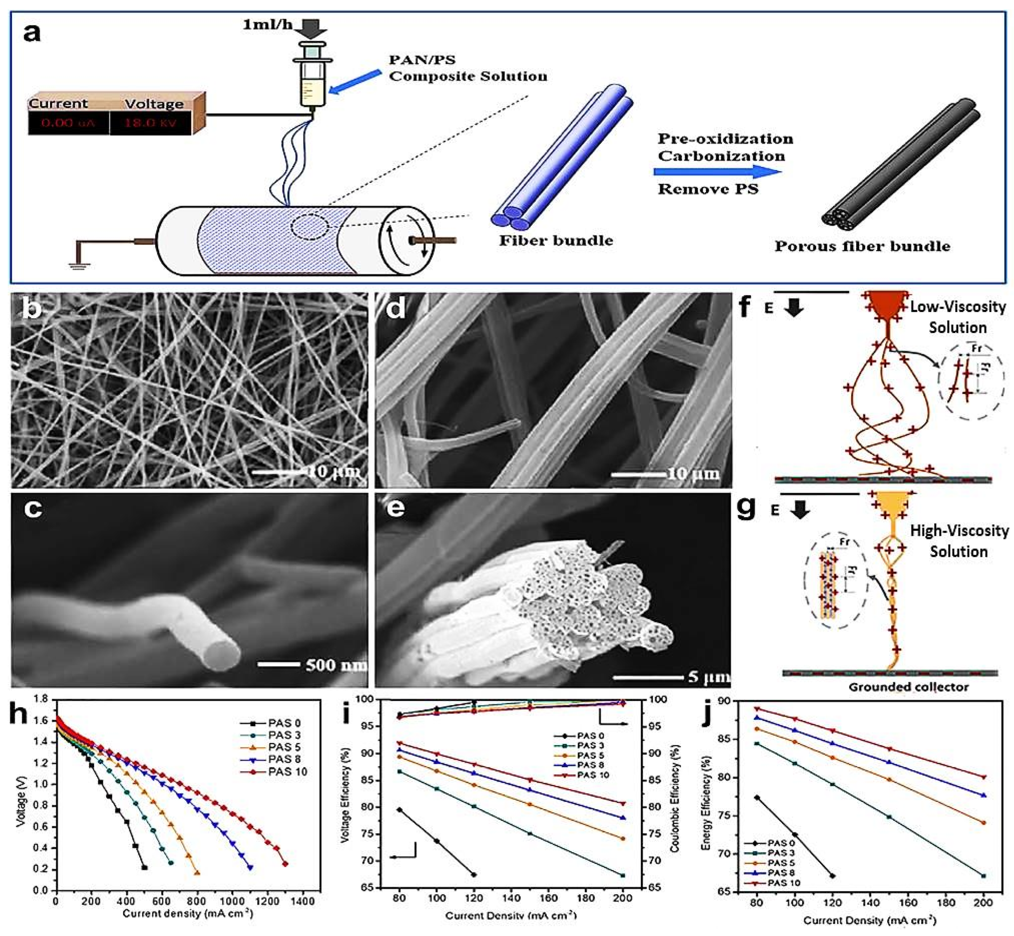
  167. Han, Z.; Wang, T.; Cai, Y.; Rong, S.; Ma, J.; Hou, L.; Ji, Y. Electrospun porous carbon nanofiber-based electrodes for redox flow batteries: Progress and opportunities. Carbon 2024, 222, 118969. [Google Scholar] [CrossRef]
  168. Wang, L.; Zhao, Y.; Lin, D.; Wang, Q.; Liu, C.; Chu, P.; Leung, P. Electrospun Carbon Nanofiber Composite Electrode with Gradient Porous Structure for Rapid Ion Transport in an All-Vanadium Redox Flow Battery. Energy Technol. 2024, 12, 2400825. [Google Scholar] [CrossRef]
  169. Li, J.; Al-Yasiri, M.; Pham, H.; Park, J. Redox flow batteries. Adv. Mater. Battery Sep. 2024, 327–347. [Google Scholar] [CrossRef]
  170. Available online: http://www.energystorage.org (accessed on 24 April 2025).
  171. Xu, D.; Zhang, C.; Li, Y. Molecular engineering redox-active organic materials for nonaqueous redox flow battery. Curr. Opin. Chem. Eng. 2022, 37, 100851. [Google Scholar] [CrossRef]
  172. Sun, J.; Zeng, L.; Jiang, H.; Chao, C.; Zhao, T. Formation of electrodes by self-assembling porous carbon fibers into bundles for vanadium redox flow batteries. J. Power Sources 2018, 405, 106–113. [Google Scholar] [CrossRef]
  173. Liang, J.; Zhao, H.; Yue, L.; Fan, G.; Li, T.; Lu, S.; Chen, G.; Gao, S.; Asiri, A.M.; Sun, X. Recent advances in electrospun nanofibers for supercapacitors. J. Mater. Chem. A 2020, 8, 16747–16789. [Google Scholar] [CrossRef]
  174. Chettiannan, B.; Dhandapani, E.; Arumugam, G.; Rajendran, R.; Selvaraj, M. Metal-organic frameworks: A comprehensive review on common approaches to enhance the energy storage capacity in supercapacitor. Coord. Chem. Rev. 2024, 518, 216048. [Google Scholar] [CrossRef]
  175. Bejjanki, D.; Puttapati, S.K. Supercapacitor Basics (EDLCs, Pseudo, and Hybrid). In Multidimensional Nanomaterials for Supercapacitors: Next Generation Energy Storage; Bentham Science Publishers: Boston, MA, USA, 2024; pp. 29–48. [Google Scholar] [CrossRef]
  176. Li, Y.; Liu, T.; Liu, Y.; Meng, F.; Cao, Z. Dual storage mechanism of charge adsorption desorption and Faraday redox reaction enables aqueous symmetric supercapacitor with 1.4 V output voltage. Chem. Eng. J. 2024, 479, 147906. [Google Scholar] [CrossRef]
  177. Xiangye, L.; Tianjiao, B.; Xin, W.; Bing, Z.; Zhenzhen, W.; Tieshi, H. Application of Electrospun Fibers in Supercapacitors. Prog. Chem. 2021, 33, 1159–1174. [Google Scholar] [CrossRef]
  178. Gopalakrishnan, A.; Sahatiya, P.; Badhulika, S. Template-assisted electrospinning of bubbled carbon nanofibers as binder-free electrodes for high-performance supercapacitors. ChemElectroChem 2018, 5, 531–539. [Google Scholar] [CrossRef]
  179. Wanison, R.; Syahputra, W.N.H.; Kammuang-lue, N.; Sakulchangsatjatai, P.; Chaichana, C.; Shankar, V.U.; Suttakul, P.; Mona, Y. Engineering aspects of sodium-ion battery: An alternative energy device for Lithium-ion batteries. J. Energy Storage 2024, 100, 113497. [Google Scholar] [CrossRef]
  180. Cui, R.; Ma, Y.; Gao, X.; Wang, W.; Wang, J.; Xing, Z.; Ju, Z. Research progress of co-intercalation mechanism electrolytes in sodium-ion batteries. Energy Storage Mater. 2024, 71, 103627. [Google Scholar] [CrossRef]
  181. Xu, G.L.; Amine, R.; Abouimrane, A.; Che, H.; Dahbi, M.; Ma, Z.F.; Saadoune, I.; Alami, J.; Mattis, W.L.; Pan, F. Challenges in Developing Electrodes, Electrolytes, and Diagnostics Tools to Understand and Advance Sodium-Ion Batteries. Adv. Energy Mater. 2018, 8, 1702403.1702401–1702403.1702463. [Google Scholar] [CrossRef]
  182. Yabuuchi, N.; Kubota, K.; Dahbi, M.; Komaba, S. Research Development on Sodium-Ion Batteries. Chem. Rev. 2014, 114, 11636–11682. [Google Scholar] [CrossRef]
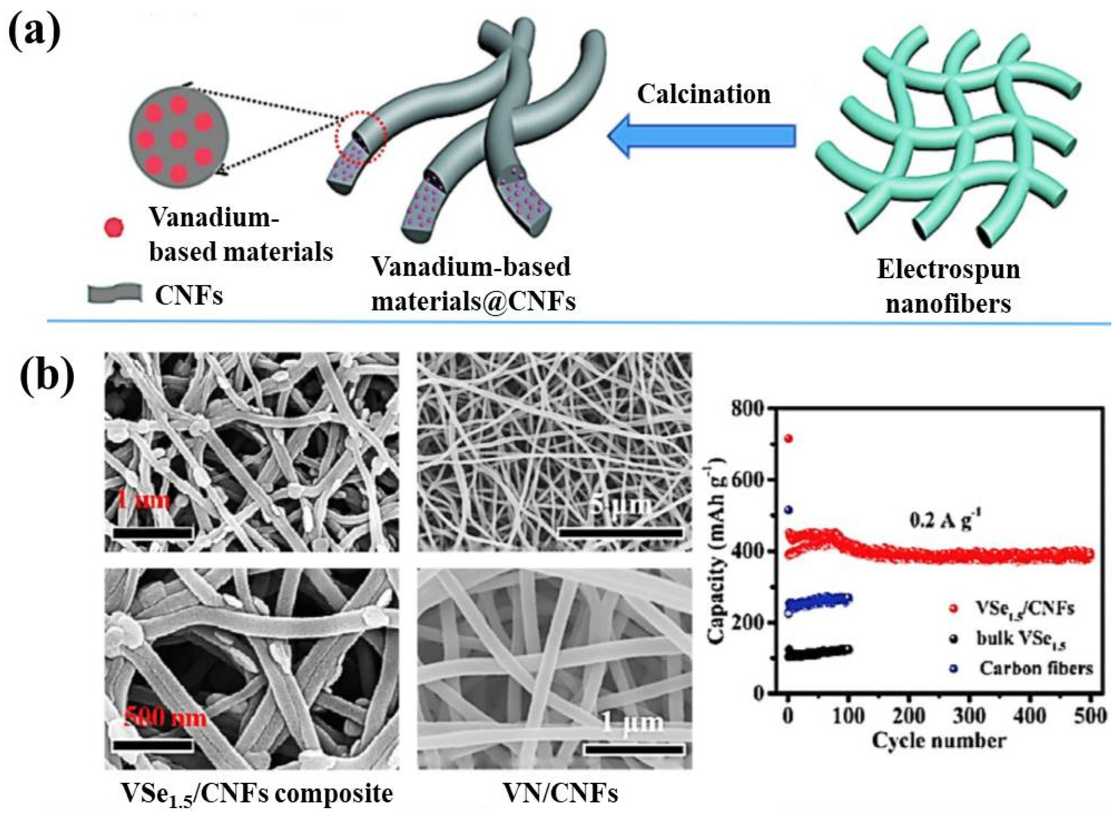
  183. Xu, L.; Xiong, P.; Zeng, L.; Fang, Y.; Liu, R.; Liu, J.; Luo, F.; Chen, Q.; Wei, M.; Qian, Q. Electrospun VSe 1.5/CNF composite with excellent performance for alkali metal ion batteries. Nanoscale 2019, 11, 16308–16316. [Google Scholar] [CrossRef] [PubMed]
  184. Xu, L.; Xiong, P.; Zeng, L.; Liu, R.; Liu, J.; Luo, F.; Li, X.; Chen, Q.; Wei, M.; Qian, Q. Facile fabrication of a vanadium nitride/carbon fiber composite for half/full sodium-ion and potassium-ion batteries with long-term cycling performance. Nanoscale 2020, 12, 10693–10702. [Google Scholar] [CrossRef]
  185. Zha, J.; Zheng, D.; Wang, Y.; Xie, Z.; Wu, G.; Qi, J.; Wei, F.; Meng, Q.; Xue, X.; Zhao, D. Coaxial electrospinning synthesis free-standing Sn/TiO2 flexible carbon fibers with sheath/core structure for advanced flexible lithium/potassium-ion batteries. Electrochim. Acta 2024, 500, 144745. [Google Scholar] [CrossRef]
  186. Gao, Y.; Yu, Q.; Yang, H.; Zhang, J.; Wang, W. The Enormous Potential of Sodium/Potassium-Ion Batteries as The Mainstream Energy Storage Technology for Large-Scale Commercial Applications. Adv. Mater. 2024, 36, 2405989. [Google Scholar] [CrossRef] [PubMed]
  187. Hao, R.; Lan, H.; Kuang, C.; Wang, H.; Guo, L. Superior potassium storage in chitin-derived natural nitrogen-doped carbon nanofibers. Carbon 2018, 128, 224–230. [Google Scholar] [CrossRef]
  188. Xu, Y.; Yuan, T.; Zhao, Y.; Yao, H.; Yang, J.; Zheng, S. Constructing multichannel carbon fibers as freestanding anodes for potassium-ion battery with high capacity and long cycle life. Adv. Mater. Interfaces 2020, 7, 1901829. [Google Scholar] [CrossRef]
  189. Wang, W.; Zhou, J.; Wang, Z.; Zhao, L.; Li, P.; Yang, Y.; Yang, C.; Huang, H.; Guo, S. Short-range order in mesoporous carbon boosts potassium-ion battery performance. Adv. Energy Mater. 2018, 8, 1701648. [Google Scholar] [CrossRef]
  190. Tai, Z.; Zhang, Q.; Liu, Y.; Liu, H.; Dou, S. Activated carbon from the graphite with increased rate capability for the potassium ion battery. Carbon 2017, 123, 54–61. [Google Scholar] [CrossRef]
  191. Qi, X.; Huang, K.; Wu, X.; Zhao, W.; Wang, H.; Zhuang, Q.; Ju, Z. Novel fabrication of N-doped hierarchically porous carbon with exceptional potassium storage properties. Carbon 2018, 131, 79–85. [Google Scholar] [CrossRef]
  192. Gao, C.; Wang, Q.; Luo, S.; Wang, Z.; Zhang, Y.; Liu, Y.; Hao, A.; Guo, R. High performance potassium-ion battery anode based on biomorphic N-doped carbon derived from walnut septum. J. Power Sources 2019, 415, 165–171. [Google Scholar] [CrossRef]
  193. Liu, X.; Huang, J.-Q.; Zhang, Q.; Mai, L. Nanostructured Metal Oxides and Sulfides for Lithium-Sulfur Batteries. Adv. Mater. 2017, 29, 1601759. [Google Scholar] [CrossRef] [PubMed]
  194. Chan, T.-C.; Chung, S.-H. Stability Enhancement of Lithium–Sulfur Batteries Using Electrospun Separator/Electrolyte Membranes. ACS Sustain. Chem. Eng. 2024, 12, 14230–14238. [Google Scholar] [CrossRef]
  195. Barghamadi, M.; Kapoor, A.; Wen, C. A Review on Li-S Batteries as a High Efficiency Rechargeable Lithium Battery. J. Electrochem. Soc. 2013, 160, A1256–A1263. [Google Scholar] [CrossRef]
  196. Zheng, G.; Yang, Y.; Cha, J.J.; Hong, S.S.; Cui, Y. Hollow carbon nanofiber-encapsulated sulfur cathodes for high specific capacity rechargeable lithium batteries. Nano Lett. 2011, 11, 4462–4467. [Google Scholar] [CrossRef] [PubMed]
  197. Wu, F.; Shi, L.; Mu, D.; Xu, H.; Wu, B. A hierarchical carbon fiber/sulfur composite as cathode material for Li–S batteries. Carbon 2015, 86, 146–155. [Google Scholar] [CrossRef]
  198. Yang, Y.; McDowell, M.T.; Jackson, A.; Cha, J.J.; Hong, S.S.; Cui, Y. New nanostructured Li2S/silicon rechargeable battery with high specific energy. Nano Lett. 2010, 10, 1486–1491. [Google Scholar] [CrossRef]
  199. Zhang, Y.; Zhang, X.; Silva, S.R.P.; Ding, B.; Zhang, P.; Shao, G. Lithium–sulfur batteries meet electrospinning: Recent advances and the key parameters for high gravimetric and volume energy density. Adv. Sci. 2022, 9, 2103879. [Google Scholar] [CrossRef]
  200. Wang, X.; Zhao, X.; Ma, C.; Yang, Z.; Chen, G.; Wang, L.; Yue, H.; Zhang, D.; Sun, Z. Electrospun carbon nanofibers with MnS sulfiphilic sites as efficient polysulfide barriers for high-performance wide-temperature-range Li–S batteries. J. Mater. Chem. A 2020, 8, 1212–1220. [Google Scholar] [CrossRef]
  201. Peng, Y.; Zhang, Y.; Wang, Y.; Shen, X.; Wang, F.; Li, H.; Hwang, B.-J.; Zhao, J. Directly coating a multifunctional interlayer on the cathode via electrospinning for advanced lithium–sulfur batteries. ACS Appl. Mater. Interfaces 2017, 9, 29804–29811. [Google Scholar] [CrossRef]
  202. Zhao, T.; Ye, Y.; Lao, C.Y.; Divitini, G.; Coxon, P.R.; Peng, X.; He, X.; Kim, H.K.; Xi, K.; Ducati, C. A Praline-Like Flexible Interlayer with Highly Mounted Polysulfide Anchors for Lithium–Sulfur Batteries. Small 2017, 13, 1700357. [Google Scholar] [CrossRef]
  203. Li, S.-Q.; Yang, J.-N.; Wang, K.-X.; Chen, J.-S. Optimization Strategies for Cathode Materials in Lithium–Oxygen Batteries. Acc. Mater. Res. 2024, 5, 1496–1506. [Google Scholar] [CrossRef]
  204. Wen, B.; Zhu, Z.; Li, F.-J. Advances and Challenges on Cathode Catalysts for Lithium-Oxygen Batteries. J. Electrochem. 2023, 29, 3. [Google Scholar] [CrossRef]
  205. Lee, J.S.; Kim, S.T.; Cao, R.; Choi, N.S.; Liu, M.; Lee, K.T.; Cho, J. Metal–Air Batteries with High Energy Density: Li–Air versus Zn–Air. Adv. Energy Mater. 2011, 1, 34–50. [Google Scholar] [CrossRef]
  206. Ogasawara, T.; Debart, A.; Holzapfel, M.; Novak, P.; Bruce, P.G. Rechargeable Li2O2 Electrode for Lithium Batteries. J. Am. Chem. Soc. 2006, 128, 1390–1393. [Google Scholar] [CrossRef] [PubMed]
  207. Zhang, J.; Yu, M.; Tao, S. Advanced electrospinning nanomaterials: From spinning fabrication techniques to electrochemical applications. Nano Res. 2024, 17, 7077–7116. [Google Scholar] [CrossRef]
  208. Zhang, G.Q.; Zheng, J.P.; Liang, R.; Zhang, C.; Wang, B.; Hendrickson, M.; Plichta, E.J. Lithium–Air Batteries Using SWNT/CNF Buckypapers as Air Electrodes. J. Electrochem. Soc. 2010, 157, A953–A956. [Google Scholar] [CrossRef]
  209. Liu, X.; Ouyang, M.; Orzech, M.W.; Niu, Y.; Tang, W.; Chen, J.; Marlow, M.N.; Puhan, D.; Zhao, Y.; Tan, R. In-situ fabrication of carbon-metal fabrics as freestanding electrodes for high-performance flexible energy storage devices. Energy Storage Mater. 2020, 30, 329–336. [Google Scholar] [CrossRef]
  210. Débart, A.; Bao, J.; Armstrong, G.; Bruce, P.G. An O2 cathode for rechargeable lithium batteries: The effect of a catalyst. J. Power Sources 2007, 174, 1177–1182. [Google Scholar] [CrossRef]
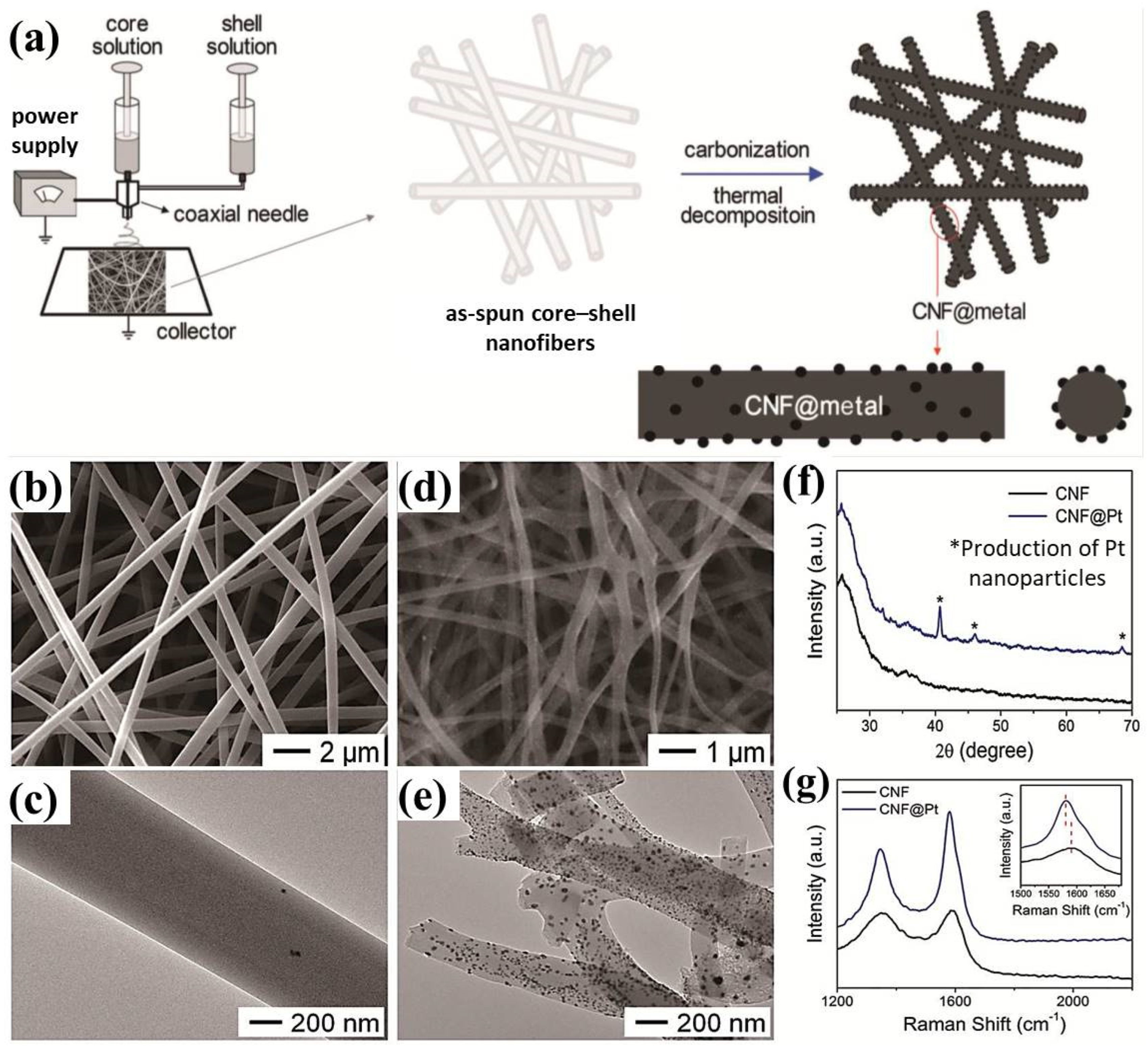
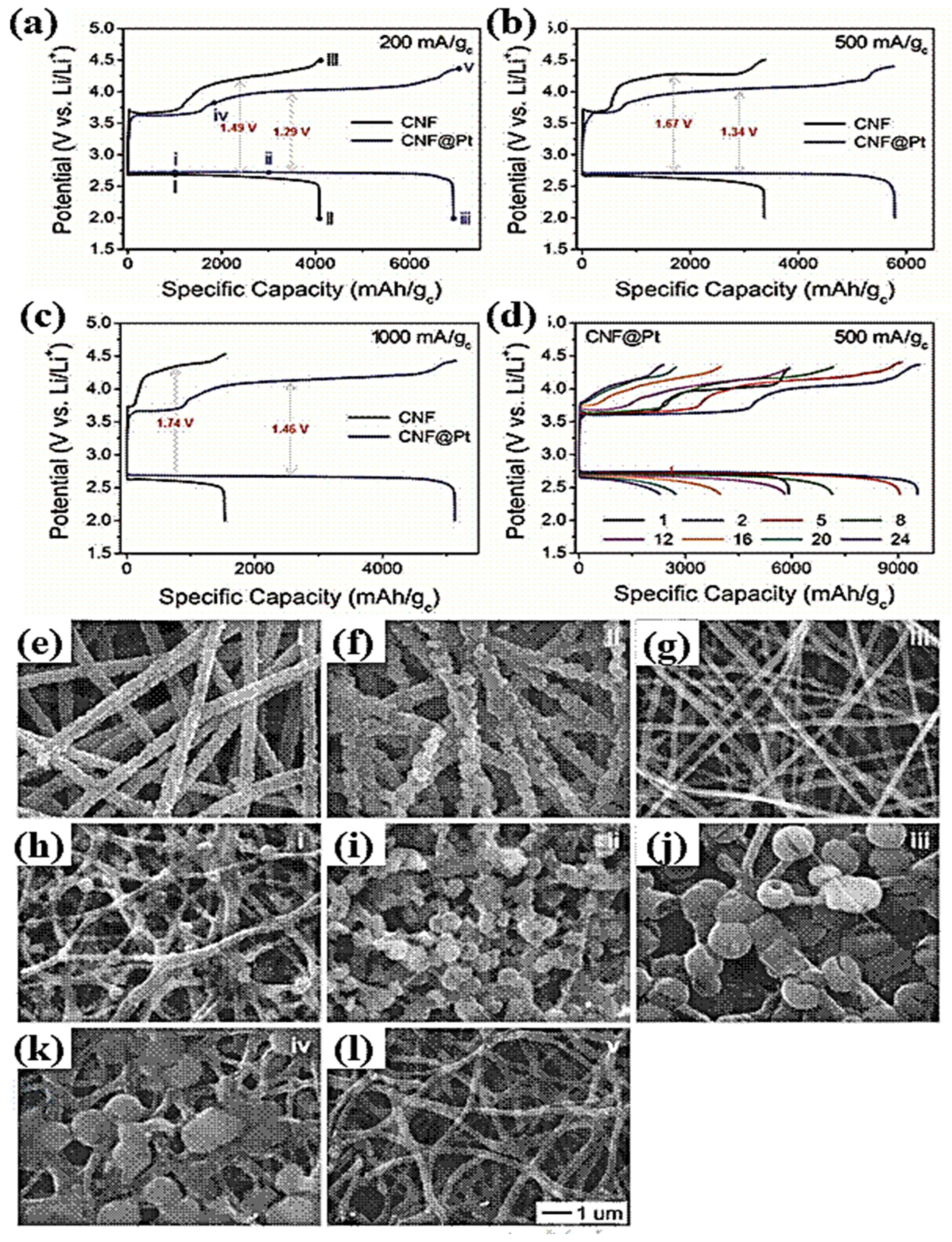
  211. Bui, H.T.; Kim, D.W.; Suk, J.; Kang, Y. Carbon nanofiber@ platinum by a coaxial electrospinning and their improved electrochemical performance as a Li− O2 battery cathode. Carbon 2018, 130, 94–104. [Google Scholar] [CrossRef]
  212. Nie, H.; Xu, C.; Zhou, W.; Wu, B.; Li, X.; Liu, T.; Zhang, H. Free-standing thin webs of activated carbon nanofibers by electrospinning for rechargeable Li–O2 batteries. ACS Appl. Mater. Interfaces 2016, 8, 1937–1942. [Google Scholar] [CrossRef]
  213. Zhou, Y.; Candelaria, S.L.; Liu, Q.; Uchaker, E.; Cao, G. Porous carbon with high capacitance and graphitization through controlled addition and removal of sulfur-containing compounds. Nano Energy 2015, 12, 567–577. [Google Scholar] [CrossRef]
Figure 1. Research articles published on electrospun nanofibers for lithium-based batteries, as itemized in the Web of Science database (2015–2024).
Energies 18 02399 g001
Figure 4. (a) Schematic illustration of melt electrospinning [94]. (b) Different heating configurations for the melting of polymers [95] (reproduced with permission from Wiley, 2011).
Energies 18 02399 g004
Figure 5. (AC) Digital images showing the deformation of a polyvinylpyrrolidone droplet in three steps under the influence of an increasing electric field, along with the mechanism (DF) for the effect of charges on the emerging polymeric droplets [101] (reproduced with permission from ACS, 2019).
Energies 18 02399 g005
Figure 6. SEM micrographs of electrospun nanofibrous membranes with various flow rates of the solution: (a) 0.1mL/h, (b) 0.5 mL/h, (c) 1 mL/h, and (d) 1.5 mL/h, [111] (reproduced with permission from Sage Publications, 2012). SEM micrographs along with their diameter distribution graphs obtained at different speeds of the drum collector, i.e., at (e) 0 rpm and (f) 2000 rpm [112] (reproduced with permission from Elsevier, 2011).
Energies 18 02399 g006
Figure 7. SEM images of electrospun nanofibrous membranes with a cross-sectional view at (a) 0 rpm, (b) 300 rpm, (c) 800 rpm, and (d) 1300 rpm (eh). Corresponding histograms of the diameter distribution (%) and (il) graphical presentation of the degree of fiber alignment [118] (reproduced with permission from ACS, 2023).
Energies 18 02399 g007
Figure 8. Spinnability view of different PEVA materials demonstrated through light microscopy images. All samples were processed at a 12 kV, 2 mL/h, and 15 cm collector distance with variable concentrations in a chloroform solution [120].
Energies 18 02399 g008
Figure 9. SEM micrographs of electrospun PLA fibers as a function of collector temperature at (a) room temperature (21 °C) and (b) 40, (c) 50, (d) 60, and (e) 70 °C [136].
Energies 18 02399 g009
Figure 10. Schematic views for three types of lithium systems: (a) lithium-ion batteries; (b) lithium–sulfur batteries; (c) lithium–oxygen batteries [137] (reproduced with permission from Elsevier, 2015), and the charge (d) and discharge (e) mechanism of lithium-ion batteries [138].
Energies 18 02399 g010
Figure 11. (a) Histogram of pure PVDF, blended PVDF: PMMA 80/20, and PVDF: PMMA 50/50 nanofibrous membrane separators concerning porosity, electrolyte uptake, and ionic conductivity. (b) XRD patterns of neat PVDF, PVDF: PMMA (80:20), and PVDF: PMMA (50:50) nanofibrous membranes [151]. (c) Theoretical and practical gravimetric energy densities of different cathode materials [152] (reproduced with permission from Elsevier, 2012). (d) Voltage range vs. Li/Li+ as a function of the charging capacity of different anode active materials [153].
Energies 18 02399 g011
Figure 12. Schematic illustration of a redox flow battery (RFB) with (a) electron movement in the circuit, ion transport in the electrolyte and across the membrane, active species crossover, and mass transport in the electrolyte. (b) Basic RFB cell arrangement [171] reproduced with permission from Elsevier, 2022).
Energies 18 02399 g012
Figure 13. Preparation process of an electrospun porous carbon fiber (bundle structure) (a), SEM images of electrodes taken after carbonization, surface morphologies of PAS 0 (b) and PAS 10 (d), cross-section views of PAS 0 (c) and PAS 10 (e), production of the fibers from precursor solutions with variable viscosities (f,g), polarization curve (h), coulombic and voltage efficiency (i), and energy efficiency (j) of a single cell with different electrodes [172] (Reproduced with permission from carbon, 2020).
Energies 18 02399 g013
Figure 14. (a) Synthesis process of carbon nanofibers (CNFs). (b) SEM images of CNFs. (c) Specific capacitance of CNFs at various current densities. (d) Specific capacitance at 1 A/g current density [177].
Energies 18 02399 g014
Figure 15. (a) Schematic illustration along with the cell structure of sodium-ion batteries [182]. Material performance representation. (b) Cathode material performance data for Na-ion batteries. (c) Anode material performance [181] (reproduced with permission from Advanced Energy Materials, 2018).
Energies 18 02399 g015
Figure 16. Preparation of electrospun vanadium-based anode materials. (a) CNFs mixed with vanadium-based materials. (b) SEM images of VSe1.5/CNF and VN/CNFs. Comparison illustration of cycle stability between carbon fibers, bulk VSe1.5, and VSe1.5/CNFs [183,184] (reproduced with permission from the Royal Society of Chemistry, 2019).
Energies 18 02399 g016
Figure 17. SEM image illustration of synthesized MCCFs with a PMMA-to-PAN ratio of (a) 0, (b) 1, (c) 2, and (d) 3; the inset picture in (c) is a TEM image of MCCF-2. (eh) Characterization of MCCF-2: (e) nitrogen adsorption–desorption isotherm; (f) pore size distribution; (g) XRD patterns; (h) Raman spectrum. (i) Schematic presentation of the unique structure of an MCCF-2 anode for potassium-ion batteries [188] (reproduced with permission from Advanced Materials Interfaces, 2020).
Energies 18 02399 g017
Figure 18. Electrochemical performances of an MCCF-2 sample electrode for PIBs: (a) current vs. voltage curves at a scan rate of 0.1 mV s−1; (b) charging–discharging on different cycles; (c) cycling performance at a current density of 50 mA g−1; (d) performances tested at 50, 100, 200, 500, 1000, 2000, and 50 mA g−1; and (e) long-term cycling performance tested at a current density of 2000 mA g−1 [188] (reproduced with permission from Advanced Materials Interfaces, 2020).
Energies 18 02399 g018
Figure 19. (a) Schematic layout of the preparation of the MnS/CNF and CNF interlayer. (b) Schematic diagrams of different interlayers suppressing the diffusion of polysulfides [200] (reproduced with permission from the Royal Society of Chemistry, 2020). (c) Schematic presentation of the cell configurations and fabrication process of PAN-NC@Cathode [201] (reproduced with permission from ACS, 2017).
Energies 18 02399 g019
Figure 20. (a) Schematic of the Li–S battery configuration with a flexible interlayer. (b,c) Cross-sectional SEM images of the interlayer. (d,e) TEM images of the interlayer [202].
Energies 18 02399 g020
Figure 21. (a) Schematic illustration of the coaxial electrospinning setup for CNF@metal mats. (b,c) SEM and TEM images of PAN/PVP-Pt (AcAc)2 core–shell nanofibers and (d,e) CNF@Pt. (f) XRD and (g) Raman spectra obtained from CNF and CNF@Pt. The inset in (g) shows magnified Raman spectra of CNF and CNF@Pt [211] (reproduced with permission from Elsevier, 2018).
Energies 18 02399 g021
Figure 22. Galvanostatic discharge–charge profiles of Li–O2 cells using CNF and CNF@Pt as cathodes for the first cycle at different current densities: (a) 200, (b) 500, and (c) 1000 mA/gc. (d) Galvanostatic discharge–charge curves of a Li–O2 cell with CNF@Pt at a current density of 500 mA/gc. Discharge was carried out until the potential reached 2.0 V vs. Li/Li⁺ in (ac) and 2.4 V vs. Li/Li⁺ in (d), with charging continuing until 100% state of charge (SOC) was achieved. SEM images were captured from the air-facing sides of the cathodes, (eg) for CNF and (hl) for CNF@Pt, at various discharge–charge states, corresponding to the points marked in (a). All SEM images were taken at the same magnification [211] (reproduced with permission from Elsevier, 2018).
Energies 18 02399 g022
Table 1. Comparison of solution electrospinning and melt electrospinning [98] (reproduced with permission from Elsevier, 2011).
Mode of ElectrospinningFiber SizeKey FactorsBenefitsDrawbacks
Solution electrospinning5 to 500 nmSolubility of solution and properties, static voltage, needle-tip-to-collector distanceVersatile, cost-effective, easy-to-operate energy storage, and filtration applicationsEnvironmental pollution, solvent availability
Melt electrospinning≥500 nmViscosity of melt, static voltage, ambient temperatureEcofriendly, safety, biomedical applicationsComplicated device, expensive, large diameter of fibers
Table 2. Melting enthalpy, crystallinity, bulk resistance, and ionic conductivity of neat PVDF, PVDF: PMMA (80:20), and PVDF: PMMA (50:50) nanofibrous membranes [151] (reproduced with permission from Springer, 2014).
Membrane Blend CompositionMelting Enthalpy
ΔHf (J/g)
Crystallinity
Xc (%)
Bulk Resistance
Rb (Ω)
Ionic Conductivity
σ (S/cm)
PVDF (100/0)53.2950.750.500.10
PVDF/PMMA (80/20)43.8441.750.290.13
PVDF/PMMA (50/50)25.3324.120.220.15
Table 3. Comparative characteristics of different batteries for energy storage [170].
Battery TypeCyclic LifeEnergy
Eff
(%)
Installation
Cost (USD/kWh)
Environmental
Influences
Response
Time
Discharge BehaviorInstallation and Maintenance
Cost (Approx USD/kWh)
Lead–acid500455500ModerateGoodBad3860
Nickel–cadium800701700ModerateGoodBad2833
Zinc–bromine250068520SeriousGoodGood3191
Sodium–sulfur300080–851000ModerateGoodGood4639
Lithium-ion200090–953000SlightGoodBad6346
All-vanadim
Redox flow
1300075–85989slightGoodGood1327
Disclaimer/Publisher’s Note: The statements, opinions and data contained in all publications are solely those of the individual author(s) and contributor(s) and not of MDPI and/or the editor(s). MDPI and/or the editor(s) disclaim responsibility for any injury to people or property resulting from any ideas, methods, instructions or products referred to in the content.

