1. Introduction
Global warming is one of the most pressing challenges of the 21st century, driven primarily by the excessive accumulation of greenhouse gases (GHGs) such as carbon dioxide (CO
2), methane (CH
4), and nitrous oxide (N
2O) in the atmosphere. The rise in global temperatures has led to severe climatic changes, including rising sea levels, extreme weather events, biodiversity loss, and disruptions to ecosystems. According to the Intergovernmental Panel on Climate Change (IPCC), limiting global warming to 1.5 °C above pre-industrial levels requires rapid and significant reductions in carbon emissions across all sectors [
1]. To achieve this, a transition toward low-carbon and carbon-neutral energy sources is essential.
More than 73% of global CO
2 emissions originate from energy production processes [
2]. Despite the increasing adoption of renewable energy sources, most electricity generation is still obtained through the burning of fossil fuels (such as coal, oil and gas) in thermal power plants. This contributes enormously to anthropogenic CO
2 emissions. Meanwhile, the transportation sector (including, e.g., automobiles, aviation, and shipping) is also heavily reliant on fossil fuels such as gasoline, diesel and fuel oil, contributing approximately 15% to global CO
2 emissions [
2]. Furthermore, the production of cement, steel, glass, and chemical products is highly energy-intensive and accounts for a significant share of industrial emissions. For example, cement, iron and steel manufacturing are responsible for over 10% of global CO
2 emissions [
2].
Figure 1 summarises global greenhouse gas emissions and energy consumption by sector. Decarbonising these sectors is therefore crucial for the benefit of humanity.
Figure 1.
Global greenhouse emission and energy consumption by sector [
2].
Figure 1.
Global greenhouse emission and energy consumption by sector [
2].
Among the solutions to rising emissions, hydrogen has emerged as a key enabler in the global push for decarbonisation. As an energy carrier, hydrogen is highly versatile and can be used to replace fossil fuels across multiple sectors. Unlike fossil fuels, hydrogen combustion produces only water vapour at the point of use. On the other hand, the environmental impact of hydrogen production depends greatly on the selected production method, which still often relies on carbon-intensive fossil fuels. The development of carbon-neutral or carbon-negative hydrogen production technologies will therefore be a crucial step in achieving carbon neutrality.
The main methods for hydrogen production are categorised by colour: green, blue, grey, yellow, white, brown, pink, or turquoise. Most hydrogen produced today is grey hydrogen, produced from natural gas in a process called steam methane reforming (SMR). However, this process generates large amounts of CO
2 as a byproduct, contributing to global emissions [
3]. Blue hydrogen is also produced via SMR, but the incorporation of carbon capture and storage (CCS) technologies prevents CO
2 from being released directly into the atmosphere. While this does prevent emissions, CCS is a newly emerging technology requiring considerable extra costs and significantly reducing the overall process efficiency [
4]. Green hydrogen is produced by electrolysis of water using renewable electricity (being classified as yellow hydrogen if solar electricity is used directly), generating pure oxygen as a byproduct. Whilst this method is carbon-neutral, its widespread adoption is being limited by factors such as scalability, supply chain issues, material costs, and high energy requirements [
4]. Furthermore, electrolysis requires copious quantities of pure water (~10 kg of water per kilogram of hydrogen) despite global water resources already being under significant stress [
5,
6], whilst also relying on per- and polyfluoroalkyl substances (PFAS, or “forever chemicals”), which are ecologically problematic and subject to increasing regulatory scrutiny [
7]. Meanwhile, pink hydrogen is generated using nuclear power and is also technically carbon neutral. Nonetheless, the controversies surrounding the safety of nuclear power and the cost of installing new nuclear power stations present significant hurdles to adoption [
6].
Turquoise hydrogen production is an emerging and highly promising alternative to the above technologies. However, a crucial difference is that the methane undergoes pyrolysis, where it is thermally decomposed into hydrogen and solid carbon, rather than CO
2 [
3]. Solid carbon is thermodynamically stable, locking the carbon in this form indefinitely without it being released into the atmosphere. As such, even when using natural gas as a feedstock, the process is carbon neutral, eliminating the need for costly CCS infrastructure. In the case that biogas is used as a feedstock, the process becomes carbon-negative, actively reducing the total amount of carbon dioxide present in the carbon cycle. Meanwhile, the generated solid carbon could be enormously useful in many industrial applications, such as in car tyres, catalyst supports, battery electrodes, black dyes, and construction materials, adding further value to the process. Furthermore, turquoise hydrogen does not require water as a feedstock, thereby reducing stress on global water resources [
8]. This is especially crucial considering that at least half of the ten countries with the highest potential for renewable energy generation experience significant water stress [
9]. Finally, methane pyrolysis is already highly compatible with existing chemical processes in the oil and gas industry and can be added or incorporated into sites with minimal footprint or impact. Overall, the above points potentially make methane pyrolysis an economically viable and highly sustainable hydrogen production route [
8,
9].
Pyrolysis is defined as an endothermic thermochemical decomposition process that breaks down hydrocarbons at high temperatures in an oxygen-deficient environment. For example, the pyrolysis of wood has been used in the manufacture of charcoal and biochar for millennia. The reaction for hydrogen production via pyrolysis of methane can be written as follows:
In the above case, sufficient thermal energy must be provided to break the covalent bonds between carbon and hydrogen in the methane molecule, which typically occurs at around 1500 °C. Methane pyrolysis typically occurs in specialised reactors, the design of which depends on how the thermal energy to break these bonds is provided. This could be provided in the form of fuel combustion, electrical energy, concentrated solar energy, plasma, or indirectly via molten metals or molten carbonates [
3,
10]. Introducing a catalyst to the process lowers the required debonding energy between the molecules [
3,
10] and can be used.
Meanwhile, the solid carbon materials generated during methane pyrolysis can take many different forms depending on the conditions in the reactor. These may include, for example, carbon black, graphite, carbon nanotubes (CNTs), graphene, amorphous carbons, or variants/hybrids of the above. Each of these is a potentially high-value product with distinct end uses and widely varying market values [
3]. Currently, many of these carbon nanomaterials are derived from petroleum products; so, another advantage of methane pyrolysis is that it provides a more sustainable route to their manufacture.
Electrification of the process enables direct energy transfer and precise temperature control, which is expected to improve overall efficiency and product purity. Meanwhile, using renewable electricity is expected to have wider benefits, such as contributing to grid balancing, providing a means for large-scale and long-term energy storage, improving energy security by reducing dependence on fossil fuel imports, and lowering process costs, especially in regions with abundant solar or wind resources.
As industries increasingly seek economically viable and environmentally friendly sustainable solutions to hydrogen production and carbon manufacture, pyrolysis-based hydrogen production is clearly a major contender for the reasons outlined above. Gaining industry-wide insights into this process and understanding the fundamental factors that govern the reaction is essential as we move towards global scale-up and commercialisation, as well as keeping abreast of recent technological advancements.
This review provides a concise overview of existing methods for turquoise hydrogen production, highlighting key challenges and recent advancements. It explores electrified technologies adopted by industries since 2020, including resistive heating, induction, and microwave methods, as well as other emerging approaches such as plasma-based, molten metal/salts, and fluidised bed systems, which can also utilise electricity as an energy source. Additionally, this study examines the market potential of turquoise hydrogen byproducts, analysing trends in technology adoption and funding. A comparative analysis of energy costs between turquoise hydrogen and green hydrogen is presented, emphasising economic considerations. Finally, this review discusses the current challenges in the field and outlines future directions for advancing turquoise hydrogen technology.
2. Technological Advances in Electrified Methane Pyrolysis
This section provides a detailed explanation of the principles behind each electrified method used for methane pyrolysis and highlights recent research developments in the field. Additionally, the key challenges associated with each method are discussed, including technical limitations, efficiency concerns, and scalability issues. Furthermore, this study introduces industries that have adopted these technologies, shedding light on their implementation in real-world applications.
2.1. Joule Heating
Joule heating involves the conversion of electrical energy into heat energy when passing a current due to the resistance of a given material. Otherwise known as resistive heating, it is an incredibly common method of heating, allowing for swift and controllable temperature elevation simply by varying the current passing through the resistor. It has a theoretical efficiency of 100% for the conversion of electrical energy into heat [
11], making it the method of choice in a wide variety of heating applications.
Joule heating is therefore a technique of great interest in methane pyrolysis applications, to overcome the endothermic nature of the reaction. The high degree of control over the amount of heat generated can allow for efficient and uniform thermal distribution within the reactor, enhancing reaction rates and hydrogen yield [
12]. Furthermore, the high theoretical conversion efficiency minimises energy loss, leading to higher overall process efficiency compared with, e.g., the use of combustion heating [
13].
Joule heating in methane pyrolysis can be either direct or indirect, based on the location of the heating element relative to the catalyst. In direct Joule heating, the catalyst must be electrically conductive and is heated directly and locally via its own internal resistance. This method is energy efficient since the catalyst is heated directly, and results in rapid temperature ramp rates. However, the catalyst material should have suitable electrical and thermal properties, limiting the choice of appropriate materials [
13].
Meanwhile, the high temperatures required for methane pyrolysis (i.e., above 1000 °C) necessitate the use of appropriate materials that can withstand such conditions for an appreciable amount of time whilst maintaining their material properties under the reducing conditions of the reactor [
13]. Examples of heating elements could include metallic alloys, ceramic materials, silicon carbide (SiC), or graphitic materials. For example, Dong et al. [
14] demonstrated catalyst-free methane pyrolysis (as well as ammonia cracking) via Joule heating, using a flexible carbon heating element to rapidly increase and precisely control the temperature (400 °C and 1700 °C within milliseconds), leading to better control of the product. In their study the impact of pulsive heating and cooling with average temperature of 600 °C was mainly investigated which resulted in over 20% conversion rated for hydrogen. They did not clearly mention the type of heater they used but suggested commercial porous elements such as carbon foam or carbon felt.
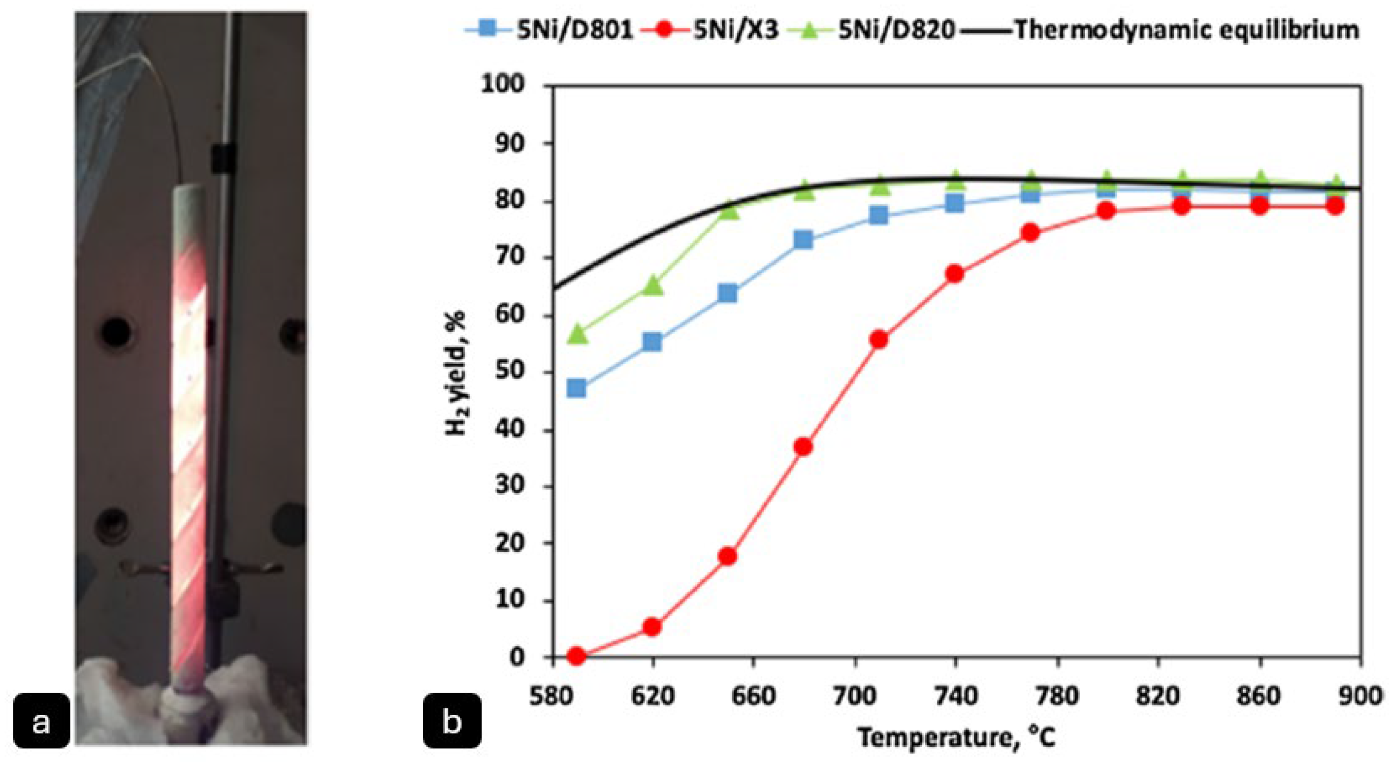
There is a lack of research specifically referencing direct Joule heating in methane pyrolysis, as most existing publications focus on applying this heating method to steam and dry methane reforming. For example, a SiC-based resistive heating element coated with Ni-based catalysts for methane pyrolysis (
Figure 2)was investigated by Renda et al. [
15]. A commercial SiC heating element served as both the catalyst support and heating medium, enabling direct Joule heating to eliminate external heat sources. The catalyst was prepared by wash coating the SiC element with a silica–mullite composite (Durapot 820) and impregnating it with 5 wt% nickel. The electrified SiC element heated itself to temperatures up to 800 °C, while reactant gases were fed into the reactor. They reported methane conversion rate and hydrogen yield of over 80% at 800 °C with heating rate of 10 °C/min.
Ratnakar R. et al. [
16] investigated hydrogen production through electrified steam methane reforming (SMR) using resistance-heated wire reactors. Their study focused on modelling nickel-based catalyst-coated wires arranged in parallel to achieve uniform ohmic heating. The electric resistance heating system generated temperatures between 900 and 1100 K, with heating rates controlled by applied voltage and wire resistivity.
Their findings demonstrated that, compared to conventional SMR, this electrified approach eliminates fossil fuel combustion, enabling net-zero operation when powered by renewable energy sources. The developed model further indicated that operating at higher temperatures (900–1100 K) and lower pressures (1–30 bar) significantly enhances methane conversion, achieving equilibrium conversion rates exceeding 98%.
In contrast, indirect Joule heating normally occurs through the reactor wall or via an inner conductive element. This gives access to a wider range of catalysts but can affect the efficiency of the reactors as the heat must transfer from the heating element to the catalyst [
17,
18,
19]. Wismann, S.T. et al. [
19], in their research, explored how combining catalytic and heating functions into a single compact unit can overcome the thermal limitations of traditional Steam Methane Reforming (SMR) systems while allowing for flexible operation with renewable energy sources. The lab-scale reactor, made from an FeCrAl-alloy tube, serves as both the structural element and resistive heater. The reactor features a nickel-impregnated washcoat catalyst, and its design enables direct ohmic heating through the application of alternating current (AC) along the tube length. The close contact between the catalyst and heating elements results in significantly improved thermal uniformity and a catalyst utilisation rate of 20–65%, compared to less than 2% in traditional systems. This efficiency is due to the elimination of thermal gradients, which normally limit reaction rates in conventional reformers. The experimental results show methane conversions exceeding 90%, matching industrial-scale reformers’ performance. Computational modelling suggests that a full-scale system could produce 2230 kmol of hydrogen per hour with a reactor volume of just 5 m
3, making it about 100 times more compact than traditional systems.
Despite the space efficiency of electrically heated reactors, scaling introduces non-uniform temperature gradients and parasitic heat losses, heavily dependent on the heating element’s thermoelectric properties. Modular configurations employing carbon monolith structures offer a viable solution [
12].
Figure 2.
(
a) SiC heating element after washcoat and Ni deposition (Ni_D820_SiC) at T = 900 °C and (
b) H
2 yield for the powder Si-based samples adopted from [
15] (permission from Elsevier, License Number: 6013711035934, 21 April 2025).
Figure 2.
(
a) SiC heating element after washcoat and Ni deposition (Ni_D820_SiC) at T = 900 °C and (
b) H
2 yield for the powder Si-based samples adopted from [
15] (permission from Elsevier, License Number: 6013711035934, 21 April 2025).
2.2. Induction Heating
Induction heating involves the application of an alternating current in an external coil to generate an alternating magnetic field, which, in turn, induces a current in a conductive material placed inside the coil, increasing the temperature via resistive heating. When applied to methane pyrolysis, this is analogous to the Joule heating effect, but, in this case, no physical connection between the catalyst and the external power source is required. As such, this is considered to be an indirect heating method. Inductive heating has previously been demonstrated for eSMR applications, in which a conductor coil is positioned outside the reactor and catalyst bed, and an inductive material is integrated into the reactor [
20]. The magnetic field produced by the external coil heats the catalyst zone through magnetic hysteresis heating or induced resistive heating. Mortensen, P.M. [
20] and his team investigated the use of nickel–cobalt (Ni-Co) nanoparticles as dual-function materials, serving both as catalysts and heating elements, with heating achieved entirely through induction. The nanoparticles were supported on a MgAl
2O
4 carrier, where nickel provided catalytic activity for steam reforming, while cobalt facilitated efficient induction heating due to its high Curie temperature (above 800 °C).
The experimental results revealed that heat generation scaled with cobalt content, confirming hysteresis heating as the dominant mechanism. By directly heating the catalyst bed, the system eliminated traditional heat transfer limitations, enabling a more compact reactor design and significantly faster startup times compared to conventional steam reforming plants. Under optimal conditions, with a total flow rate of 20 Nl/h and a power input of 1600 W, the system demonstrated highly efficient hydrogen production, achieving 98% methane conversion (at 760 °C).
One consideration for high-temperature applications for inductive heating (e.g., >1000 °C for catalyst-free methane pyrolysis) is that ferromagnetic materials lose their permanent magnetism above the Curie temperature (T
n). This presents an upper limit to the useful temperature for a given material. For that reason, the magnetic susceptor for induction-driven methane pyrolysis (or eSMR) is normally based on materials with a high Curie temperature, such as cobalt (T
n ~ 1300 °C) [
21,
22]. Therefore, induction is more commonly used for lower temperature hydrogen production processes, such as dry reforming of methane (DRM), in which methane is reacted with CO
2 to form hydrogen and carbon monoxide, a reaction that typically occurs at 600 to 1000 °C [
23]. Furthermore, the use of catalysts can improve the feasibility of induction heating by reducing the decomposition temperature of methane [
20,
21]. Another disadvantage of inductive heating is that the heating efficiency is only around 90% [
15,
16] compared with 100% for direct resistive heating. Furthermore, induction provides a higher initial cost and complex setup compared with Joule heating [
24].
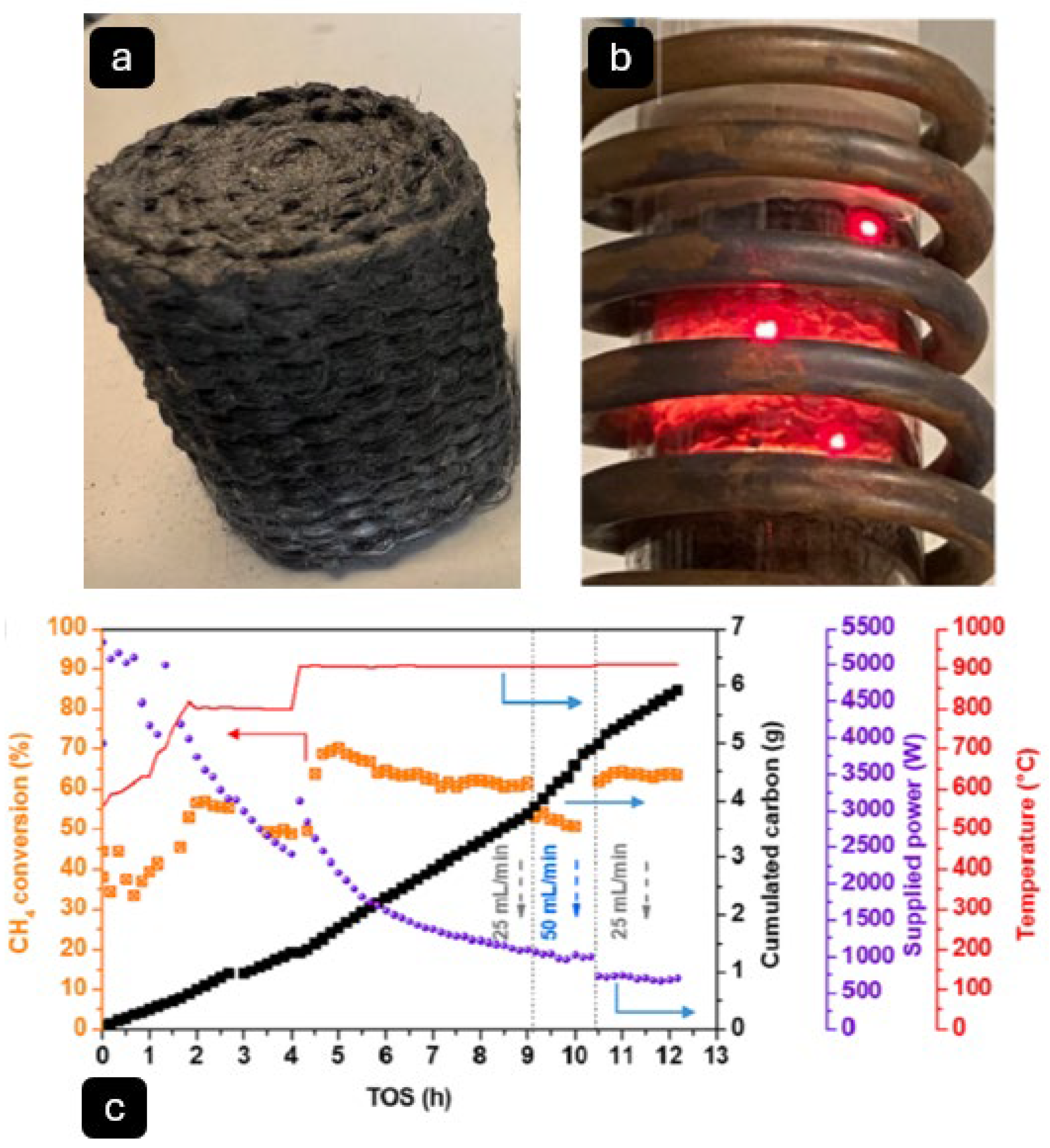
In the study by Essyed, A [
25], the catalytic decomposition of methane (CMD) using a few-layer graphene (FLG)-coated macroscopic composite under induction heating (IH) for methane pyrolysis was investigated (
Figure 3). The FLG was deposited onto a Zetex substrate. The CMD process was conducted at temperatures ranging from 500 °C to 900 °C. The catalyst exhibited high methane conversion rates, reaching 60% at 750 °C and 63% at 900 °C, with stable performance over sixteen hours. The hydrogen yield was significant, with selectivity around 95%, while minor C
2 hydrocarbons (ethane, ethylene, acetylene) were detected as intermediates. Raman spectroscopy demonstrated the graphitic nature of the deposited carbon. This method presents a viable pathway for turquoise hydrogen production using renewable energy and low-cost catalysts (energy intensity of ~44 kWh/kg H
2). Future work will explore the role of the insulator substrate and magnetic field effects in greater detail.
Induction heating has been used by researchers for low-temperature pyrolysis for syngas and bio-fuel [
26,
27] applications. Wu. L et al. [
26] presented an innovative biomass pyrolysis method that integrates an induction heating reactor with metallic particles to enhance biofuel production efficiency. The key advancement lies in incorporating steel balls into the biomass, which are directly heated by electromagnetic induction, creating an “in-situ heating” effect. The experimental results highlight notable performance improvements. The pyrolysis completion time was reduced by up to 28.9%, demonstrating a faster and more efficient process. Additionally, total energy consumption decreased by up to 26.5%, underscoring the method’s energy-saving potential.
Beyond efficiency gains, the introduction of metallic particles substantially increased the hydrogen (H
2) yield compared to conventional induction heating without additives. At 600 °C, the H
2 volume fraction rose from 18.2 vol% to 24.7 vol%, marking a 35.7% improvement. Also, Yan Y. [
27] explored the use of an electromagnetic induction heating fluidised bed reactor (IHFBR) to enhance hydrogen-rich syngas production from tobacco stem (TS) pyrolysis. The system utilised a tungsten rod for rapid heating, achieving rates of up to 20.3 °C/s, and incorporated silica sand to optimise heat transfer. Operating at 700 °C, the IHFBR significantly improved the syngas yield compared to traditional methods.
These findings highlight the superior efficiency of induction heating over traditional combustion-based methods, which depend on fuel burning. The precise and uniform heating provided by induction is particularly advantageous for methane pyrolysis, where maintaining stable high temperatures is essential for maximising hydrogen yield and minimising carbon deposition. However, the challenges outlined earlier persist, requiring further advancements to optimise the process and enhance its scalability and efficiency.
Induction heating presents inherent limitations for methane pyrolysis due to material constraints (ferromagnetic requirements, Curie temperature effects) and suboptimal energy efficiency (RF conversion losses). When applied to metallic reactors, this method introduces distinct scaling challenges that require careful mitigation. The fundamental mechanism of induction heating—generating eddy currents—results in simultaneous heating of both catalyst and reactor walls. This dual heating effect can lead to excessive wall temperatures that potentially compromise structural integrity [
12].
To address these limitations, two primary optimisation strategies emerge: reactor miniaturisation and thermal management. Scaling down to small-diameter tubes improves energy efficiency by concentrating electromagnetic energy on the catalyst rather than the reactor walls. However, this approach does not fully eliminate wall heating concerns, mandating the implementation of robust external cooling systems for temperature control.
A complementary solution involves integrating heat recovery systems, such as bayonet-type reactor designs. These systems capture and recycle excess thermal energy, significantly enhancing overall process efficiency. Together, these adaptations help overcome the core challenges of induction heating for methane pyrolysis applications [
12].
Figure 3.
(
a) Zetex
® (Quebec City, QC, Canada) cloth after coated with a layer of FLG followed by oven drying at 110 °C, (
b) induction heating reactor and homogeneous temperature in the catalyst bed, and (
c) methane conversion, H
2 production, power input for (FLG)-coated Zetex cloth, adopted from reference [
25] (this is an open access article under the CC BY license,
http://creativecommons.org/licenses/by/4.0/ (accessed on 5 March 2025)).
2.3. Microwave-Induced Methane Pyrolysis
Another way to access high temperatures for chemical processes is via microwave heating. Microwaves interact with materials that have dielectric properties, causing them to vibrate and generate heat. In the case of methane pyrolysis, microwave radiation is used to selectively heat a catalyst inside a reactor to the point where the thermal energy can break down methane into hydrogen and solid carbon. This enables efficient pyrolysis at locally high temperatures without the need for an external heat source.
In methane pyrolysis, microwave heating is a relatively new development. It offers several advantages over conventional methods such as heating by electric heating or by combustion of fossil fuels. One key benefit is the ability to selectively and rapidly heat materials [
28]. For example, microwaves can selectively heat the catalyst itself, which quickly becomes the hottest component in the reactor, facilitating methane decomposition.
Dadsetan et al. [
29] demonstrated a microwave methane pyrolysis reactor based on a fluidised bed design (
Figure 4), and determined that investigated the impact of carbon particle inclusion in improving microwave energy absorption and achieved hydrogen selectivity of over 90% at 1000 °C with a 50–50% methane–nitrogen mixture. The report was published as a part of the technology hired by the Aurora Hydrogen.
Figure 4.
(
a) Experimental setup for the microwave-driven methane pyrolysis, and (
b) performance of microwave-driven methane pyrolysis with 50–50% methane–nitrogen mixture with a flow rate of 0.2 L/min @ 1 atm. Reproduced from reference [
29] (permission from Elsevier, License Number: 6013730136820, 21 April 2025).
Aurora Hydrogen is a startup company founded in 2021, headquartered in Alberta, Canada. Their technology centres on the utilisation of microwave energy to convert natural gas into hydrogen and solid carbon, in a catalyst-free process. The company claims that the process requires 80% less electricity compared with water electrolysis whilst eliminating the need for water. Although the organisation itself has not published formal research papers, their technology has been validated with academic partners. In 2021, researchers at the University of Toronto conducted bench-scale reactor tests on Aurora’s proprietary hydrogen production processes [
30,
31]. In these reports, a fluidised-bed reactor was used in combination with microwave heating. Activated carbon served as a seed material, placed into quartz tubes. When irradiated with microwaves, these absorbed the microwave energy, increasing the temperature to ~1000 °C. This thermal energy was then transferred to methane gas molecules (99% purity, 1 atm) flowing through the fluidised carbon particle bed, facilitating the decomposition to carbon and hydrogen [
29]. The reactor was operated for a cumulative 500 h, reportedly maintaining greater than 90% hydrogen selectivity throughout the process. The morphology of the carbon product was reported to be “sand-like”, with the relatively large particle size facilitating safe transport, and with target applications in, e.g., the construction industry (as a replacement for construction sand) [
32]. The technology is claimed to be highly modular and scalable, allowing for on-site hydrogen production at various scales at a cost of ~USD 1.50 per kilogram, even without accounting for potential revenue from the sale of the solid carbon byproduct [
33]. Notably, the company has received USD 3 million in funding from Natural Resources Canada, and over USD 1 million from the NGIF Accelerator [
34].
Furthermore, free volume, packed bed, fluid wall, and tubular microwave reactors have also been studied [
10]. However, fluidised bed type reactors typically result in improved performance, due to, e.g., reactor blockage when using other methods [
35].
One major issue with this method is the non-uniformity of microwave absorption, especially for large scale beds [
36], due to limitation in penetration depth. In the study conducted by Pérez-Botella [
36], a temperature gradient of 60 °C was observed within a cylindrical sample with a diameter and height of 9.7 cm, with minimum and maximum recorded temperatures of 30 °C and 90 °C, respectively. Therefore, larger adsorbent beds experience temperature gradients, with surface regions heating faster than the core. A moving (rotating) reactor design reported by Julian, I [
37] demonstrated positive impact on reducing the temperature gradient in scaled-up reactor. Also, switching the direction of the microwave [
38] offers a potential solution for scaling up microwave-driven catalytic processes by minimising temperature gradients within the reactor. The hybrid heating systems that combine microwaves with conventional heating methods is another proposed alternative [
36] to mitigate penetration limitations and improve thermal uniformity.
2.4. Plasma Methane Pyrolysis
A plasma can be created by supplying a gas with a large amount of electrical energy (via the application of high voltage) at a specific temperature and pressure. The process excites and ionises the gas molecules, generating electrons which then collide with other molecules, creating more ions and electrons.
This method can also be used in methane pyrolysis, in which plasma is initiated in a methane atmosphere using, e.g., a plasma torch, and maintained using a high-voltage electric field, generating hydrogen and solid carbon. The temperature in the plasma can range from, e.g., 1000 to 3500 °C [
10], and different varieties of plasma reactor used in this application include arc plasma, microwave plasma, or corona discharge plasma [
39,
40].
Some of the advantages of plasma methane pyrolysis include high methane conversion ratios [
29], and the generation of high-quality carbon nanomaterials [
41]. However, challenges such as high energy demand [
41], electrode erosion during operation, and reactor stability issues must be addressed before large-scale industrial adoption [
40]. Despite these challenges, plasma pyrolysis remains a promising method for decarbonised hydrogen production with potential applications in clean energy and carbon material industries.
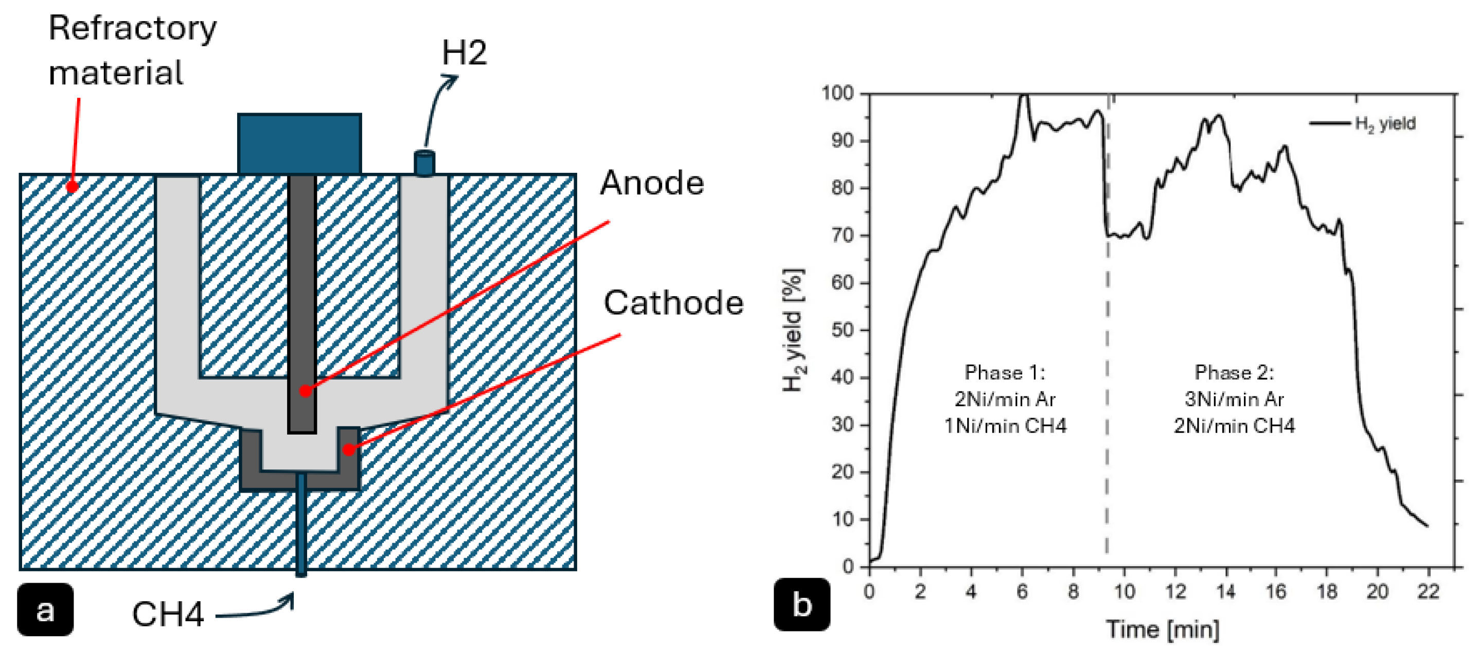
Daghagheleh, O. et al. [
42] investigated the feasibility of using a plasma furnace for methane pyrolysis to produce hydrogen (H
2) and solid carbon (
Figure 5). The reactor consisted of a graphite hollow cathode and anode, with argon (Ar) and methane (CH
4) introduced as plasma gases. The experiments were conducted at high temperatures, typical of plasma pyrolysis, exceeding 1200 °C, which allowed for non-catalytic decomposition of methane. The methane conversion rate was highly efficient, reaching up to 100% under optimal conditions. The hydrogen yield varied between 60% and 100%, depending on process parameters such as gas composition, power input, and gas flow rate. Higher power input and lower methane content in the plasma gas were found to enhance H
2 yield, while increased gas flow reduced residence time and yield.
The produced solid carbon was characterised using scanning electron microscopy (SEM) and energy-dispersive X-ray (EDX) analysis, revealing a highly pure (>99% carbon), fluffy, and fine-structured material with dendritic morphology.
Figure 5.
(
a) Schematic illustration of the plasma reactor, (
b) hydrogen yield rate for 3 and 5 Ni/min inlet gas flow generated (
a) and adopted (
b) from reference [
42] (Daghagheleh et al., 2024, open access article distributed under the terms and conditions of the Creative Commons Attribution (CC BY) license,
https://creativecommons.org/licenses/by/4.0/, (accessed 2 March 2025)).
Daghagheleh, O. et al. [
42] reported plasma arc instability in their study when introducing methane (CH
4) into the plasma gas mixture due to its higher ionisation energy compared, while carbon deposition on reactor surfaces creates alternative conductive paths that further disrupt the arc. Solutions include optimising the gas composition (e.g., limiting CH
4 to ≤40% in Ar plasma) and employing higher-voltage power supplies to maintain stable operation. Also, they reported that rapid carbon deposition leads to reactor fouling, which blocks the plasma arc and reduces hydrogen yield, limiting operational runtimes to 10–15 min in lab settings. This could be mitigated through vertical reactor designs with continuous carbon removal mechanisms or modular reactor systems that allow for maintenance without full shutdowns [
42].
Electrode degradation also presents a significant challenge as graphite electrodes erode under extreme temperatures, altering arc geometry and reducing efficiency over time. Potential solutions involve using advanced refractory materials (e.g., tungsten) or water-cooled electrodes, along with dynamic positioning systems to compensate for wear. The energy efficiency also remains suboptimal in big-scale reactors due to heat dissipation where an integrated heat recovery system can mitigate that [
42].
In conclusion, while the process plasma demonstrates excellent hydrogen yields (60–100%) at laboratory scale, successful industrial implementation will require coordinated advances in reactor engineering, material science, and process control systems to overcome these scaling challenges. Future development should focus on pilot-scale validation of these solutions to demonstrate technical and economic feasibility at commercial scales [
42].
In 2012, the U.S. company Monolith Materials began the development of a plasma-based pyrolysis process for methane decomposition [
43]. Their technology relies entirely on high-temperature plasma to drive the reaction, enabling the production of varying grades of solid carbon product (such as carbon black), claiming a 70% reduction in CO
2 emissions compared with conventional furnace-based carbon manufacturing methods. Their carbon black product is already applied in vehicle tyres in North America. Meanwhile, their hydrogen product is planned to be used to generate ammonia, for use in the fertiliser industry, helping to decarbonise agriculture [
44].
Futhermore, HiiROC Ltd., is UK-based company (Hull, UK) which has developed a proprietary technology known as Thermal Plasma Electrolysis (TPE), using patented plasma torches to dissociate methane, reportedly enabling a more efficient and highly controlled process [
45]. Their process operates at elevated pressures (25 to 50 bar) and the company reports enhanced conversion rates and mass throughput. They have established strategic partnerships with industry players including Siemens (focussed on control systems for automation) [
46], and Cemex for applications of the technique in industrial settings such as cement plants [
47], and have secured a total of ~USD 50 million in funding since 2019, with investors including Melrose Industries, HydrogenOne Capital Growth, Centrica, Hyundai, and Kia [
48,
49].
Levidian, a UK-based company (Cambridge, UK), has also developed a microwave-based methane pyrolysis technology. Their patented LOOP method employs focused microwaves in a low-temperature (around 1000 °C), at atmospheric pressure and catalyst-free process to create a methane plasma, decomposing the molecules into hydrogen and solid carbon in the form of graphene [
50,
51].
The designed nozzle enhances methane residence time through its vortex-driven gas dynamics and optimised plasma confinement. By generating three nested vortices (primary, secondary, tertiary) via the Coandă effect and a tapered geometry, the nozzle forces methane to spiral repeatedly through the plasma zone, significantly extending its exposure to microwave radiation. The tertiary vortex creates a low-pressure core that traps methane in the high-energy region, while CFD simulations confirm a 3–5× increase in residence time compared to conventional nozzles. After cracking, the carbon species enter the afterglow chamber, where a controlled temperature gradient (800–1200 °C) and rapid cooling ensure sufficient time (~10–100 ms) for orderly graphene formation with purity exceeding 99.5%. Raman spectroscopy analyses confirm the production of single- and multi-layer graphene flakes (D/G~0.7–1.2) [
51].
Furthermore, the company claims that the system can be retrofitted to existing systems, and is ideal for on-site deployment at locations with any methane source, including landfill sites, biogas facilities, flare gas sites, or natural gas plants [
52]. Levidian’s LOOP technology has garnered significant investment, securing GBP 27 million in 2022 in a Series A funding round, and is currently pursuing Series B funding with a target of GBP 50 million in early 2025 [
53].
2.5. Molten Metal/Salt Methane Pyrolysis
In molten metal salt methane pyrolysis, methane is thermally decomposed into hydrogen and solid carbon by passing it through a molten phase catalytic medium at high temperature. The molten phase material is typically a metal (such as tin, iron or nickel), a metal alloy (such as Ni-Co, Fe-Cr), or a metal salt (such as Ni-Bi, Cu-Bi) [
54], whilst methane gas is typically bubbled through this liquid (resulting in the system sometimes being known as a “bubble reactor”).
The molten material serves multiple roles in the reactor. It acts as a catalyst, decreasing the required temperature for breaking down methane into hydrogen and carbon. It acts as a reaction medium through which methane passes through and reacts, generating the products. It also acts as a heat transfer medium—the supply of thermal energy in this method is typically provided via resistive or induction heating [
54,
55], which makes it suitable for using green energy sources. Finally, the molten phase makes it relatively simple to separate the solid carbon product from the molten phase, since the relatively low density of carbon means it readily floats to the surface, where it can be collected, allowing the continuous production of hydrogen and carbon and preventing catalyst deactivation by carbon deposition [
56]. In addition, its relatively compact size makes it a feasible option for commercialisation [
57].
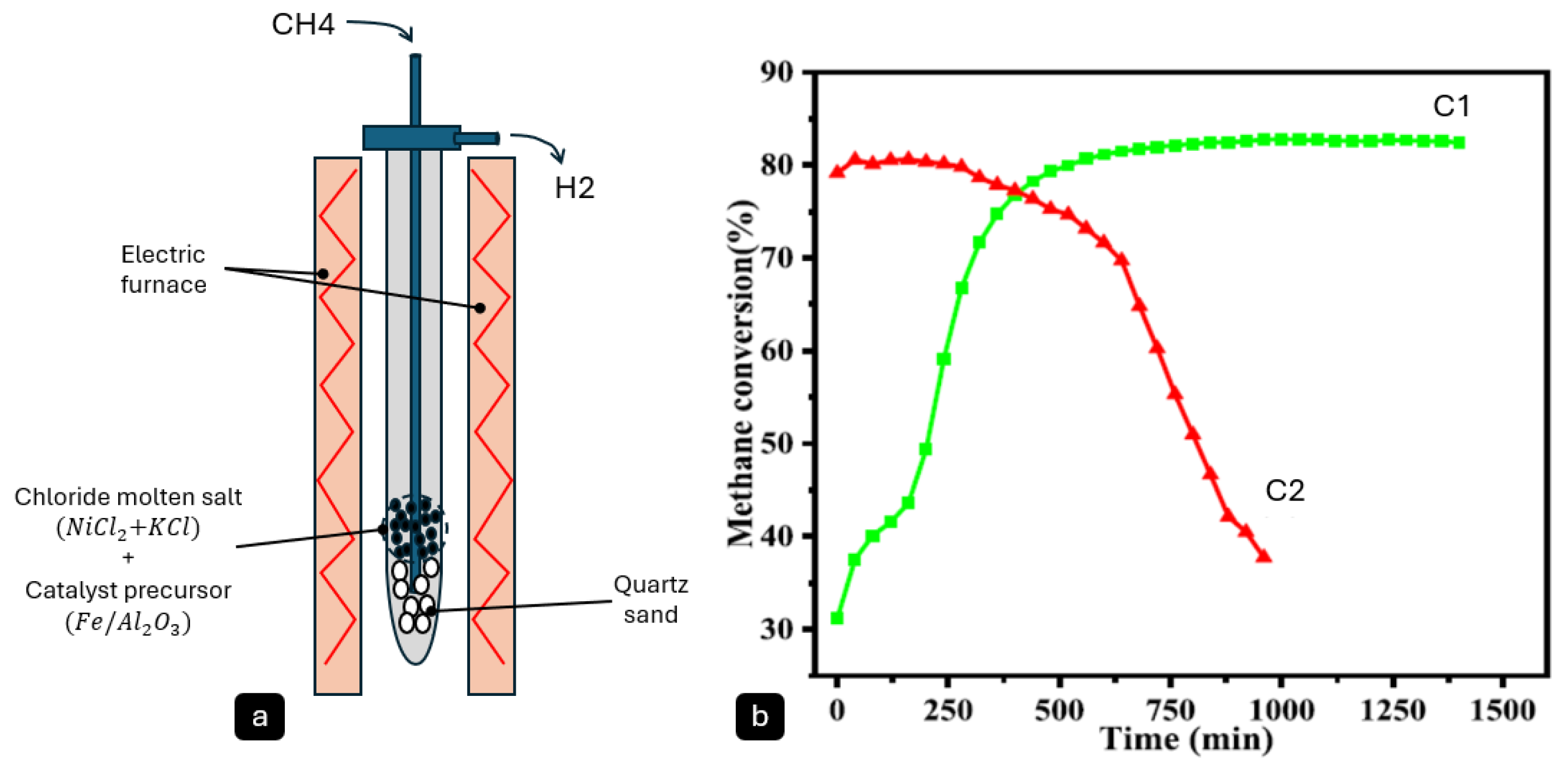
Molten metal/salt reactors are normally considered two-phase (liquid–gas) reactors. However, some researchers such as Hu, X. et al. [
58] have reported three-phase (gas–liquid–solid) reactors (
Figure 6) in which solid Fe-Ni catalyst particles are floated in molten salt (NiCl
2-KCl). The results of their study confirmed high activity and long-term stability of this system, with over 16 h of stable methane conversion at a rate of 81% at 800 °C. Using Raman spectroscopy, the carbon product was reported to an I
D/I
G ratio of 0.79, indicating the production of moderately graphitic carbon.
Figure 6.
(
a) Schematic of an Ni-Fe/Al2O
3 reactor, and (
b) reproduced methane conversion curves of C1: molten salt promoted Ni-5Fe/Al
2O
3-M, and C2: Ni-5Fe/Al
2O
3-IM without the molten salt at 800 °C. (
a) adopted and (
b) reproduced from reference [
58] (permission from Elsevier, License Number: 6013710545406, 21 April 2025).
The efficiency of the molten metal/salts method is strongly influenced by the properties of the molten bath, including the melting temperature, thermal conductivity, and catalytic activity. Single-phase metals such as Fe, Cu, Bi, Sn, and Pb offer low melting points and high thermal conductivity but generally exhibit relatively low catalytic activity [
56]. To address this, metal alloys (e.g., Ni-Bi, Cu-Bi) can be used to enhance catalytic performance [
59], though they introduce the risk of metal contamination in the carbon byproduct [
60]. Carbon purity of between 55% and 92.6% was reported in the literature for this method depending on the catalyst and process conditions [
56,
60]. Catalyst contamination in the carbon product reduces process efficiency by increasing the costs associated with carbon purification and replenishing the wasted catalyst metal.
Meanwhile, metal/metal salt mixtures facilitate catalyst separation from the carbon product through simple processes like water washing owing to their low density and high solubility in water [
61]. However, using pure molten salts leads to relatively low catalytic activity [
61] but it is more cost-effective since salts typically have a lower melting point compared to pure metals [
62,
63].
Beyond material selection, several operational factors impact reaction rate and byproduct formation, including the feed system, molten material composition, and reactor temperature [
62]. These parameters all influence the structure of the resulting carbon.
Most published reports are limited to lab-scale studies and do not highlight the challenges that method could face at an industrial level. Herberger et al. [
64] covered the challenges in a liquid metal bubble reactor in their study, concluding that a primary challenge in methane pyrolysis using molten metal reactors is carbon management and reactor fouling. Continuous carbon deposition leads to accumulation in the reactor head, which can result in blockages and process instability. Mitigation strategies include passive flotation gravity discharge systems, which facilitate carbon removal via gravitational separation, and active mechanical extraction methods, such as scrapers, to prevent excessive buildup.
Another reported critical issue is weeping (liquid metal leakage), where molten tin infiltrates gas inlets through orifices due to pressure fluctuations, leading to clogging and operational inefficiencies. This can be addressed through prechamber designs with tin collection vessels and active pressure stabilisation systems to regulate gas flow and prevent uncontrolled leakage. The authors highlighted that bubble dynamics and residence time present additional scale-up challenges. Increasing reactor diameter alters bubble formation, reducing interfacial heat transfer efficiency. Optimised multihole orifice configurations help maintain small bubble sizes, while controlled gas flow rates ensure appropriate residence time for methane conversion. Temperature control and heat management become increasingly complex in large-scale systems. Effective solutions include active thermal zoning (heating and cooling regions), high-performance insulation, and heat recovery systems to maintain uniform reactor temperatures. Material degradation of critical reactor components, such as graphite electrodes and quartz liners, necessitates the use of advanced refractory materials and modular reactor designs to facilitate replacement of high-wear parts. Finally, achieving industrial-scale throughput at current flow rates would require impractical volumes of molten material (tin, in this case).
Addressing these challenges requires pilot-scale validation of carbon removal systems and multihole orifice designs, alongside hybrid reactor architectures and dynamic process control strategies for optimisation. Future research should focus on large-scale prototype demonstrations to bridge the gap between laboratory feasibility and industrial deployment.
Molten Industries is an innovative USA-based (Oakland, CA, USA) startup founded in 2021, which hires resistive heating in their molten metal/salt methane pyrolysis processes. Their innovative approach integrates turquoise hydrogen from methane pyrolysis into the iron reduction process for the steel industry.
Their patented technology involves the thermochemical decomposition of hydrocarbon feedstock in a horizontally aligned reactor. The reactor can operate either catalyst-free or catalyst-assisted (molten salts or metals inside the chamber). The molten material facilitates the reaction and serves as a collector for the carbon product. Depending on the choice of catalyst, the decomposition temperature can range from 400 °C to over 1000 °C, with a setup limit of 2000 °C. While resistive heating is the default method, they claim their technology can also be adapted for induction heating and microwave heating [
65]. Their system achieves over 90% methane decomposition at 1200 °C. Additionally, by varying thermal decomposition conditions, they have demonstrated the ability to produce hydrogen byproduct carbon in both amorphous and graphitic forms [
65].
The reactor consists of a cylindrical or crucible-shaped chamber, lined with high-temperature refractory materials to withstand extreme operating conditions ranging from 1000 to 1500 °C. At the core of the system is a molten metal bath, which serves as the primary reaction medium. Hydrocarbons are introduced into the bath through strategically positioned gas injectors or submerged nozzles, ensuring effective mixing and thermal exposure. A key feature of the reactor’s design is its rotational motion, which plays a vital role in temperature regulation and gas dispersion. By continuously rotating, the system prevents localised overheating, maintains a uniform temperature distribution, and enhances hydrocarbon–metal interaction. Furthermore, this rotation significantly improves carbon separation efficiency. As solid carbon particles form, they are subjected to centrifugal forces, causing them to either float or settle based on their density, thereby facilitating continuous removal and minimising buildup within the reactor [
65].
In 2024, Molten Industries partnered with United States Steel Corporation and CPFD Software to develop a pilot system supplying clean hydrogen to a direct reduced iron (DRI) shaft furnace. This project, supported by a USD 5.4 million grant from the U.S. Department of Energy, aims to demonstrate carbon-neutral steel production [
66].
2.6. Fluidised Bed
The term “fluidized bed” encompasses both molten catalyst beds (also known as bubble reactors) and gas–solid fluidised beds. Molten catalyst beds can operate as either gas–liquid or gas–liquid–solid systems, where the fluidising medium is a liquid, such as molten metal or salt. While both approaches utilise fluidisation to enhance reaction kinetics, they differ fundamentally in their mechanisms. Gas–solid pyrolysis relies on surface-mediated reactions, which can suffer from catalyst deactivation over time. In contrast, molten catalyst pyrolysis employs a dynamic liquid phase (e.g., molten metal or salt), which helps sustain catalytic activity and improve carbon management efficiency.
A detailed discussion of molten catalyst systems is provided in
Section 2.5. This section, however, focuses on the gas–solid phase. For clarity, throughout this paper, the term “fluidized bed” will specifically refer to the gas–solid phase.
The fluidised bed technique involves the suspension of solid particles (such as a catalyst, inert media, or a reactant) in an upward-flowing gas. At a sufficient flow rate, the solid phase particles are physically agitated, creating a quasi-fluid-like state. This physical agitation enhances heat and mass transfer in the reactor, ensuring uniform temperature distribution and improved reaction kinetics. This technique is widely utilised in the chemical, petrochemical, energy, and environmental industries due to its ability to provide high surface area contact between reactants and catalysts, significantly improving process efficiency [
35,
67,
68]. Its continuous operation makes it a scalable and industrially viable solution [
35,
69]. The effectiveness of the fluidised bed method is heavily dependent on key parameters such as particle size, temperature, and flow rate, all of which influence reaction stability and performance.
Chew J. et al. [
68] studied the challenges that the fluidised bed method has faced in the last decade. They identified that one of the primary challenges in fluidised bed reactors is particle agglomeration and defluidisation. Fine particles in the reactor tend to stick together due to cohesive forces, particularly at high temperatures [
35]. This agglomeration can disrupt fluidisation, leading to operational inefficiencies and, in severe cases, reactor shutdowns. To address this issue, researchers have explored several solutions, including optimising bed material properties [
70], incorporating inert particles [
71] to reduce cohesion, and adjusting gas velocity to maintain stable fluidisation. Additionally, real-time monitoring techniques, such as endoscopic-laser [
72] and high-speed imaging [
73], have been employed to detect early signs of agglomeration and prevent defluidisation.
Another major issue in fluidised bed technology is uneven gas–solid mixing and distribution. In large-scale reactors, achieving uniform mixing is difficult, leading to localised temperature variations, incomplete reactions, and reduced overall efficiency [
68]. To overcome this, improvements in distributor plate design [
74] have been implemented to enhance gas dispersion. Optimising fluidisation velocity and utilising computational fluid dynamics (CFD) simulations [
75] help predict and improve gas–solid interactions. Additionally, secondary air injection has been found to significantly enhance mixing, ensuring better reaction uniformity and thermal efficiency.
A third significant challenge is erosion and wear of reactor components due to the continuous movement of solid particles. This abrasive action leads to material degradation in key reactor parts, such as the distributor plate and reactor walls, resulting in increased maintenance costs and reduced equipment lifespan [
68]. A practical solution to this problem is the use of wear-resistant materials, such as ceramic coatings and high-strength alloy steels [
76], which offer greater durability under harsh operating conditions but increase system cost.
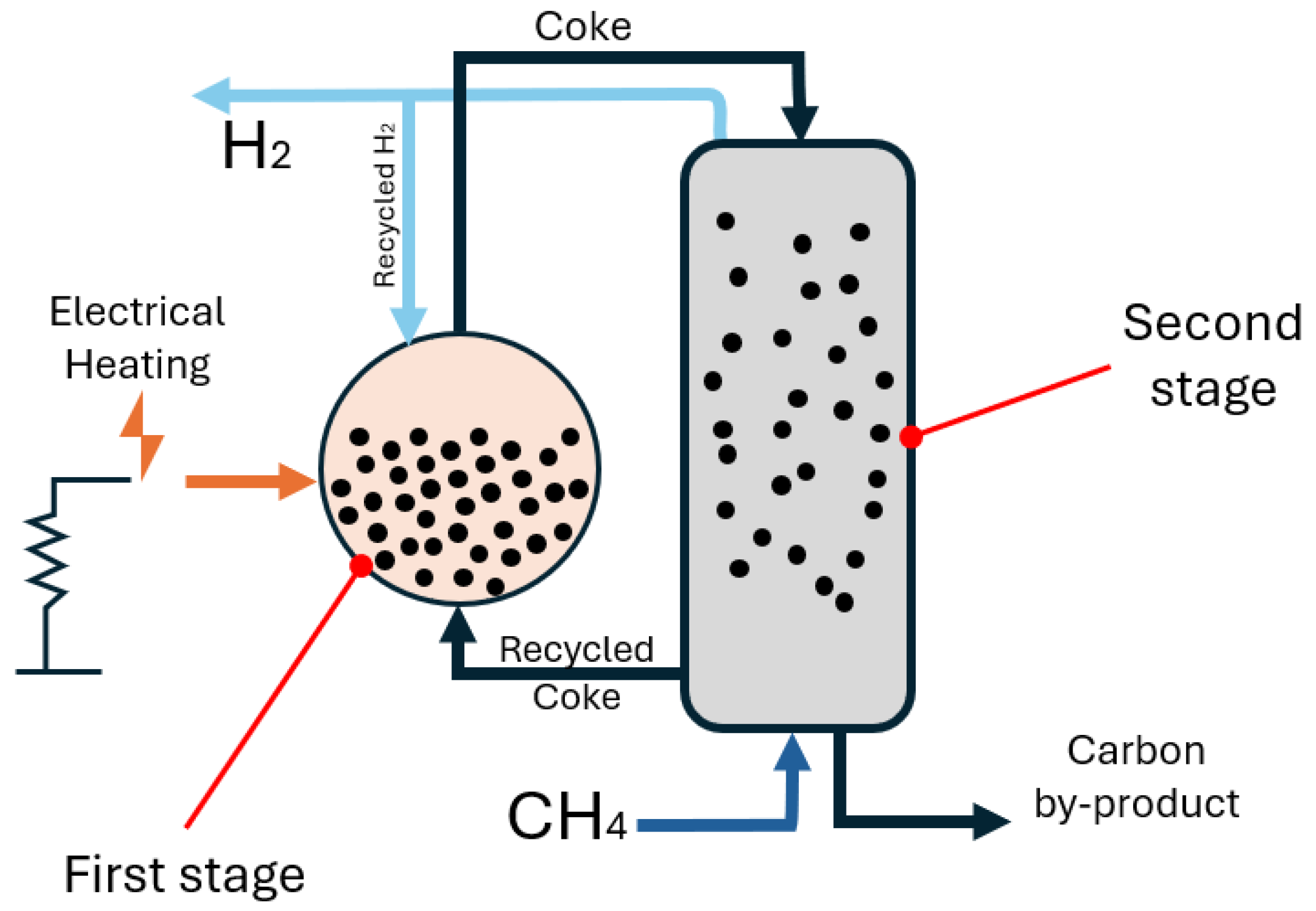
ExxonMobil has a patented fluidised bed for methane pyrolysis with electrical heating [
77]. Their technology, shown in
Figure 7, employs electrically heated fluidised beds of coke particles to decompose methane into hydrogen and solid carbon efficiently. It utilises a two-stage fluidised bed reactor, where the first stage heats coke particles above 1000 °C in a hydrogen-rich environment to prevent coke deposition on heating elements. The heated coke is then transferred to the second stage, where it facilitates methane pyrolysis, producing hydrogen and additional carbon deposits. A counter-current flow arrangement ensures efficient gas–solid interaction, with methane and hydrogen moving upward while coke particles circulate downward. A pneumatic transport system recycles coke particles using hydrogen gas, minimising contamination.
Hydrogen is then separated using membrane separation or pressure swing adsorption, with unconverted methane recycled to maximise efficiency, potentially exceeding 90% overall conversion—outperforming conventional systems (60–80%). The process avoids combustion, preventing side reactions that reduce efficiency. The solid carbon byproduct is expected to be of high purity, suitable for applications such as electrodes, though its properties require further characterisation. The system’s multi-stage design, electric heating, and hydrogen recycling offer a scalable and high-efficiency approach to methane pyrolysis.
Meanwhile, ExxonMobil is pursuing a potential market for the hydrogen produced by this method by manufacturing pyrolysis burners. It has installed 44 pyrolysis burners capable of operating on up to 100% hydrogen fuel in its Baytown, Texas, facility [
78].
Figure 7.
Schematic illustration of the Exxonmobil fluidised bed reactor generated from [
77].
Figure 7.
Schematic illustration of the Exxonmobil fluidised bed reactor generated from [
77].
A summary of the advantages, limitations, and performance of each of the above-mentioned methane pyrolysis technologies is presented in
Table 1 and
Table 2, offering a clear comparison of their relative effectiveness.
Table 1.
Strengths and limitations of various methane pyrolysis approaches.
Table 1.
Strengths and limitations of various methane pyrolysis approaches.
| Method | Advantages | Disadvantages |
|---|
| Joule Heating | - Direct heating, efficient energy use
- Simple reactor design
- Scalable for industrial use
- Fast response time | - Requires conductive reactor walls
- Potential carbon deposition on electrodes and deactivation |
| Induction Heating | - Precise and uniform heating
- No direct contact between heat source and gas
- Fast response time | - Requires metallic susceptors or catalysts
- Limited material choices |
| Plasma Pyrolysis | - Very high methane conversion (>99%)
- Can produce high-purity carbon | - High energy consumption
- Expensive plasma generation
- Reactor degradation
- Complex reactor design |
| Microwave Heating | - Selective heating (only absorbs in specific materials)
- Fast start-up time
- Can enhance catalyst performance | - Requires microwave-absorbing catalysts
- Shallow microwave penetration
- Uneven heating possible |
| Molten Metal/Salt Reactors | - Continuous operation
- Good methane conversion
- Carbon easily separated from liquid medium | Large amount
- Complex reactor design
- Potential contamination from metals
- Needs a large amount of molten material |
| Fluidised Bed (Gas–Solid) | - Good heat and mass transfer
- High methane conversion
- Easy carbon removal | - Requires precise control of gas flow
- Reactor fouling from carbon deposition
- Particle agglomeration |
Table 2.
Performance comparison of various methane pyrolysis technologies, including graphitisation degree (measured by Raman spectroscopy ID/IG ratio), carbon purity, hydrogen yield, methane conversion efficiency, operating temperature, and energy intensity.
Table 2.
Performance comparison of various methane pyrolysis technologies, including graphitisation degree (measured by Raman spectroscopy ID/IG ratio), carbon purity, hydrogen yield, methane conversion efficiency, operating temperature, and energy intensity.
| Method | Temperature
(°C) | Methane Conversion Efficiency *
(%) | Hydrogen Yield **
(%) | Energy Intensity
(kWh/kg H2) | Graphitisation Degree
(Raman, ID/IG) | Carbon Purity
(%) | Ref. |
|---|
| Joule heating | 800 | 85 | 82 | 56.7 | 0.85 | - | [15] |
| Induction | 900 | 63 | 95 | 43.2 | 0.85 | - | [25] |
| Microwave | 1000–1200 | 90 | 90 | - | 1–1.3 | 99 | [29,79] |
| Plasma | 1600–1700 | 95> | 90–100 | 100 | 0.5–0.85 | 99.5> | [80,81,82] |
| Bubble reactors | 1200 | 90 | - | - | 0.79–1.1 | 60–91 | [55,56,61] |
| Fluidised bed | 950–1000 | 85–90 | - | - | 0.8–0.9 | - | [67,83] |
3. Economic Feasibility and Byproducts Utilisation
This section explores the economic feasibility of methane pyrolysis, analysing the capital costs (CAPEX) and operational costs (OPEX), the energy requirements, and potential revenue streams. Methane pyrolysis technologies can generate emission-free turquoise hydrogen from natural gas at a relatively low cost, capturing carbon in an indefinitely stable solid form. In contrast, electrolysis can generate emission-free green hydrogen from water, but the technique remains expensive and relies on large amounts of pure water. Directly comparing these two technologies in terms of hydrogen production costs will provide insight into their respective economic feasibilities and their potential for widespread adoption. The cost of electricity and gas varies based on geographic location and consumption volume. In this study, the average electricity and gas prices are sourced from the Department for Energy Security and Net Zero (DESNZ) Annual Report (2023–2024) [
84] and the Office of Gas and Electricity Markets (OFGEM) [
85]. A simple comparison of the energy and cost requirements for turquoise and green hydrogen is presented below (
Table 3). For turquoise hydrogen, methane pyrolysis requires theoretical minimum 5.2 kWh of energy per kilogram of hydrogen produced [
41]. At an electricity price of GBP 0.18 per kWh, the energy cost amounts to GBP 0.936 per kg of hydrogen. Additionally, the process consumes 4 kg of methane per kg of hydrogen, where methane provides 14.5 kWh of energy per kg. Given a gas price of GBP 0.038 per kWh, the cost of methane is calculated as GBP 2.63 per kg of hydrogen. Summing both contributions, the estimated levelised cost of hydrogen (LCOH) for turquoise hydrogen is GBP 3.14 per kg.
Meanwhile, for green hydrogen, electrolysis requires minimum theoretical 39.4 kWh of electricity per kilogram of hydrogen produced [
86,
87]. With the same electricity price of GBP 0.18 per kWh, the energy cost reaches GBP 7.09 per kg of hydrogen. The feedstock requirement includes 9 kg of water per kg of hydrogen, with a water price of GBP 0.001 per kg for purified water, resulting in a negligible feedstock cost of GBP 0.009 per kg of hydrogen. Consequently, the total LCOH for green hydrogen is GBP 7.10 per kg, with the primary cost driver being electricity consumption.
The calculations indicate that the price of turquoise hydrogen is potentially around half that of green hydrogen, using the selected inputs, indicating a clear advantage of this process. It is also noted that the LCOH values quotes here are significantly higher than the ultimate targets for the cost of hydrogen (i.e., ~USD 1/kg); however, this will be impacted significant by energy costs, which are expected to drop as the uptake of wind and solar increases [
88]. Importantly, the LCOH of turquoise hydrogen in the table does not consider the potential revenue from sales of the solid carbon byproduct. This is explored in more detail below.
Table 3.
Calculation of the levelised cost of hydrogen (LCOH) for water electrolysis and methane pyrolysis.
Table 3.
Calculation of the levelised cost of hydrogen (LCOH) for water electrolysis and methane pyrolysis.
| | Theoretical Energy Required to Produce 1 kg of H2 (kWh/kg) [89] | Feed (Gas/Water) Required for 1 kg of H2 (kg) | Electricity Price
(GBP/kWh) [84] | Gas Price
(GBP/kWh) [85] | Water Price
(GBP/kg) | Gas HHV
(kWh/kg) | Levelised Cost of Hydrogen (LCOH) |
|---|
| Turquoise H2 | 5.2 | 4 | 0.18 | 0.038 | 0.001 | 14.5 | GBP 3.14 |
Green
H2 | 39.4 | 9 | GBP 7.10 |
A major advantage of methane pyrolysis for turquoise hydrogen production is the ability to sell the solid carbon byproduct as a high-value material. Depending on the process conditions, the resulting carbon can take the form of, e.g., carbon black, graphite, graphene, or carbon nanotubes [
4,
90]. These carbon materials can then be used in other industrial applications, creating economic benefit, and can also potentially lead to environmental benefits across multiple industries by, e.g., avoiding emissions in carbon manufacture.
Carbon black is a porous nanomaterial comprising clusters of spheroidal nanoparticles. It is made at vast scale via a spray-pyrolysis method, using petrochemicals a feedstock and fossil fuels to power the process. The material is used as, e.g., a major component in car tyres (accounting for ~70% of carbon black production [
91]), as catalyst support, or as a black dye in plastics and paints. The global carbon black market is expected to grow from USD 20.6 billion in 2022 to USD 42.2 billion by 2032, reflecting a compound annual growth rate (CAGR) of 6.9%. Meanwhile, the annual global production capacity of carbon black is expected to increase by 1.4% over the same period. Importantly, the main producers of carbon black (such as Orion S.A [
92]) are shifting toward more sustainable manufacturing to reduce their CO
2 footprint. Methane pyrolysis could provide a suitable alternative.
Graphite is the most familiar form of solid carbon to many people, being used as the writing element in pencils. It has high electrical and thermal conductivity, making it the material of choice for electrodes in batteries and heat sinks and as an element in electric motors [
90]. Most graphite occurs naturally in limestone deposits, and is mined, with significant associated emissions. Furthermore, natural graphite is classed as a critical raw material (CRM), meaning it has significant economic importance but is associated with supply chain risks. The global graphite market is projected to grow at a CAGR of 3.7% from 2024 to 2030, driven primarily by its increasing use lithium-ion batteries and as a refractory material. In particular, the use of graphite in lithium-ion battery production is expected to experience the highest revenue growth, with a CAGR of 4.4% over the forecast period, reflecting the rising demand for energy storage solutions [
93]. According to the International Renewable Energy Agency (IRENA), EV battery demand is projected to exceed 4300 GWh per year by 2030, representing a five-fold increase over 2023 levels [
94]. Furthermore, market demand and supply projections predict a 10% shortfall in graphite production by 2035 [
95,
96]. As such, this is another huge potential market for graphite produced by methane pyrolysis.
Carbon nanotubes (CNTs) are a relatively recent discovery and comprise tiny tubules of graphitic carbon. These have a long list of impressive properties, including extremely high electrical conductivity, resistance to corrosion, low density, and very high tensile strength [
97]. CNTs are gaining significant attention in energy storage technologies, aerospace applications, flame retardants, catalysis, photovoltaics, and structural reinforcement of plastics and concrete [
89,
98]. CNTs market share in 2024 by application is shown in
Figure 8. Traditionally, CNTs have been considered extremely expensive and niche materials. However, recent advancements in CNT manufacturing techniques, particularly chemical vapour deposition (CVD), have led to a significant reduction in production costs. The CNT market is forecast to grow at a CAGR exceeding 14% between 2024 and 2030. Multiwall CNTs occupy 93.6% of the market share, whilst single-walled CNTs (SWCNTs) are expected to grow at a CAGR of 11.7% by 2030 [
99]. One particularly promising application for CNTs is to replace copper in electrical wiring. There is a shortfall between copper production (both by mining and recycling) and copper demand, creating a critical supply gap [
100,
101], underscoring an urgent need for alternative materials, for which CNTs are a clear candidate. Companies such as DexMAT, Nanocomp Technologies, and Toray Industries have made significant advancements in CNT-based wire production, narrowing the performance gap between copper and carbon-based conductors. This presents a huge market opportunity for CNTs produced in a sustainable manner via methane pyrolysis.
Figure 8.
Carbon nanotubes market share by application, 2024 [
99].
Figure 8.
Carbon nanotubes market share by application, 2024 [
99].
Methane pyrolysis presents a compelling alternative to electrolysis for hydrogen production, offering a lower levelised cost of hydrogen while generating a valuable solid carbon byproduct. The economic viability of turquoise hydrogen is further enhanced by the potential revenue streams from carbon materials such as carbon black, graphite, and carbon nanotubes, each of which has expanding market demand across various industries. The ability to integrate methane pyrolysis into existing infrastructure, combined with the push toward sustainable carbon manufacturing, makes it a promising pathway for scaling up hydrogen production with reduced emissions. As energy prices continue to fluctuate and technological advancements drive down production costs, methane pyrolysis could play a crucial role in the transition toward a low-carbon economy.
4. Challenges and Future Directions
The reduction in emissions in the UK has been significantly influenced by the transition to natural gas from oil and coal. However, to achieve Net Zero by 2050, this sector still requires further decarbonisation, as, according to the International Energy Agency (IEA), natural gas accounted for 46% of total CO
2 emissions from fuel combustion in the UK in 2022 [
102].
As shown in
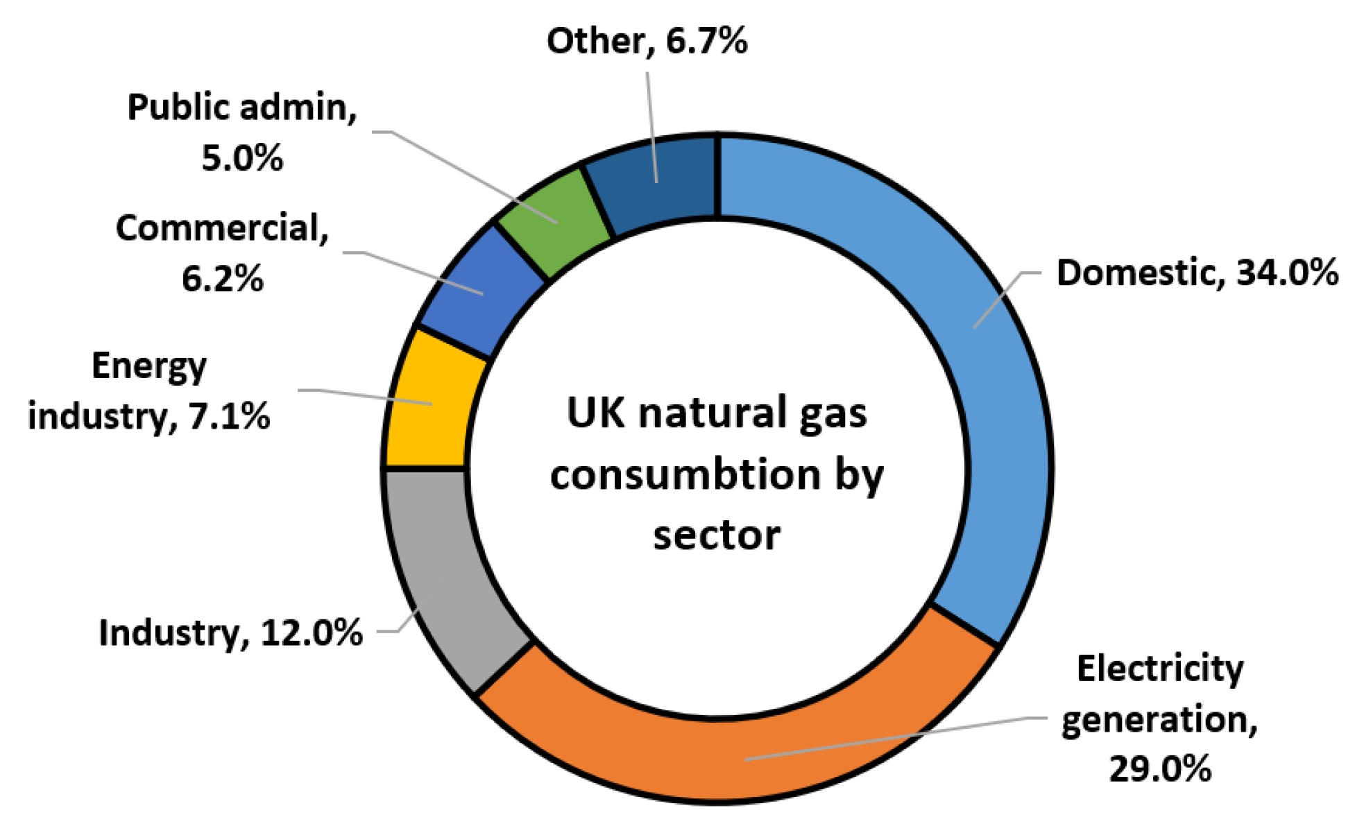
Figure 9, the domestic sector, electricity generation, and industry are the three largest consumers of natural gas in the UK in 2023 [
103]. Domestic gas use includes space and water heating, as well as gas-powered appliances such as ovens and hobs [
103].
Figure 9.
UK sectoral consumption of natural gas, 2023 [
103].
Figure 9.
UK sectoral consumption of natural gas, 2023 [
103].
Policies on domestic heating have undergone significant changes in the past couple of years. A plan to phase out new gas boilers by 2035, stated in the policy announcement of September 2023 [
104], was scrapped in January 2025 [
105]. Obligations to replace gas boilers with heat pumps and restrictions on the installation of gas boilers in new houses were, therefore, abandoned. However, the Boiler Upgrade Scheme (BUS) was retained to encourage heat pump installations, offering grants of GBP 7500 [
105]. Although heat pumps are considered the primary mechanism for decarbonising the domestic sector, in 2025, the government will assess the latest evidence and consult on the role of hydrogen in home heating [
106].
The UK Emissions Trading Scheme (ETS) caps emissions for large-scale emitting industries like power generation, heavy industry, and aviation. Companies that exceed their carbon emission limits must purchase allowances. The UK Government applies a market-based approach in which natural gas users are expected to be stimulated to decarbonise through the ETS, since allowances tend to increase in price, creating a financial incentive to adopt low-carbon technologies [
106]. The ETS was introduced in 2021 as a replacement for the EU ETS. It is closely linked to the UK’s Carbon Budgets, which were established under the Climate Change Act 2008 and are now being developed for every period of five years [
107]. This interconnection ensures that total UK emissions remain within national targets.
The UK Hydrogen Strategy Update 2024 recognises the potential of hydrogen in decarbonising hard-to-abate sectors, such as chemicals and heavy transport, complementing broader electrification efforts [
108]. Additionally, the government plans to review the viability of technologies such as the direct reduction in iron using natural gas or hydrogen for primary steel production [
108].
The previously mentioned policies and legislation are only part of the UK’s broader decarbonisation strategy for natural gas users. As evaluated by the Climate Change Committee (CCC), the effectiveness of these measures can be hindered by policy inconsistency. Policy reversals, delays, and mixed messaging present a major barrier to achieving the UK’s climate targets and have the potential to undermine consumer confidence and investor certainty [
109]. Currently, only one-third of the required emissions reductions are supported by credible plans [
109]. Additionally, the UK’s energy security strategy prioritises the long-term phase-out of natural gas consumption, which creates uncertainty for methane pyrolysis. The government has declared electrification as the primary means of decarbonising the oil and gas sector between 2027 and 2040 [
110,
111]. Within the UK’s hydrogen policy, there is strong support for blue and green hydrogen, while methane pyrolysis lacks clear backing.
In the UK Hydrogen Strategy (2021), methane pyrolysis is classified as a “nascent technology”, with the next steps focused on R&D and innovation [
112]. While it acknowledges the potential of the technology, it also creates a sense of uncertainty, as there are no explicit commitments for scaling up its deployment.
The UK’s commitment to the decarbonisation of natural gas users creates a fertile environment for the growth and expansion of hydrogen technology. Besides the widely acknowledged technologies for the production of blue and green hydrogen, new technologies, such as methane pyrolysis, play an important role in the technology mix. Therefore, for the successful further deployment of the hydrogen mix, it would be beneficial to enhance the consistency of the policy framework. A stable regulatory environment will boost investor confidence in innovation and enable a smoother transition for natural gas users. In addition, a number of measures can be proposed. Firstly, it is necessary to simplify access to and understanding of key policies. At present, there are a number of difficulties in interpreting these policies. For example, the trade association Renewables UK explains in its guide to investors and policymakers how the Hydrogen Production Business Model works, noting that this policy framework may be somewhat complicated to navigate [
113]. Hydrogen producers and innovative projects are also likely to face this issue. It is important to present policy information in a way that ensures stakeholders have the most complete and up-to-date information at the time it is needed.
Secondly, to support innovation in hydrogen production, it is important to increase the inclusivity and participation of startups and representatives of different types of hydrogen production in policy consultations. Expanding their involvement will allow policy decisions to be made with greater consideration for the needs and prospects of developing technologies.
Also, if the UK is positioning itself as a global leader in the hydrogen economy and innovation, it should initiate the development of standards that will ensure the industry’s harmonisation at the local and then potentially global level. The lack of international standards poses a risk to widespread adoption of hydrogen [
114].
This list of recommendations is not exhaustive and represents only a fraction of the possible measures. A full analysis is beyond the scope of this article and requires a separate study.
5. Conclusions
The increasing demand for clean hydrogen production has driven significant advancements in electrified methane pyrolysis technologies, offering a low-emission and economically viable alternative to conventional hydrogen production methods. This review has explored the state-of-the-art approaches, including Joule heating, induction heating, microwave-assisted pyrolysis, plasma-based decomposition, molten metal reactors, and fluidised bed systems, highlighting their efficiencies, scalability, and potential for decarbonising industrial sectors. Among these methods, plasma and molten metal-based pyrolysis show promise in achieving high methane conversion rates and valuable carbon byproducts, while microwave and induction heating offer energy-efficient pathways with reduced operational costs.
Despite these advancements, challenges such as carbon deposition, energy consumption, reactor stability, and material selection remain critical barriers to widespread adoption. Further research is needed to optimise reactor designs, integrate renewable electricity sources, and enhance carbon byproduct utilisation to improve the overall feasibility of turquoise hydrogen production. Additionally, policy support, infrastructure development, and investment in emerging technologies will play a crucial role in accelerating commercialisation.
Looking ahead, short-term advancements are expected to focus on pilot-scale deployment and cost reduction, while medium-term efforts will likely refine efficiency and establish carbon markets. In the long-term, large-scale adoption of methane pyrolysis could reshape the global hydrogen economy, providing a sustainable and carbon-neutral energy carrier. With continued innovation and strategic collaboration between research institutions, industry leaders, and policymakers, electrified methane pyrolysis has the potential to become a cornerstone technology in the transition toward a clean hydrogen economy.


