
Review of Ammonia Oxy-Combustion Technologies: Fundamental Research and Its Various Applications


Abstract
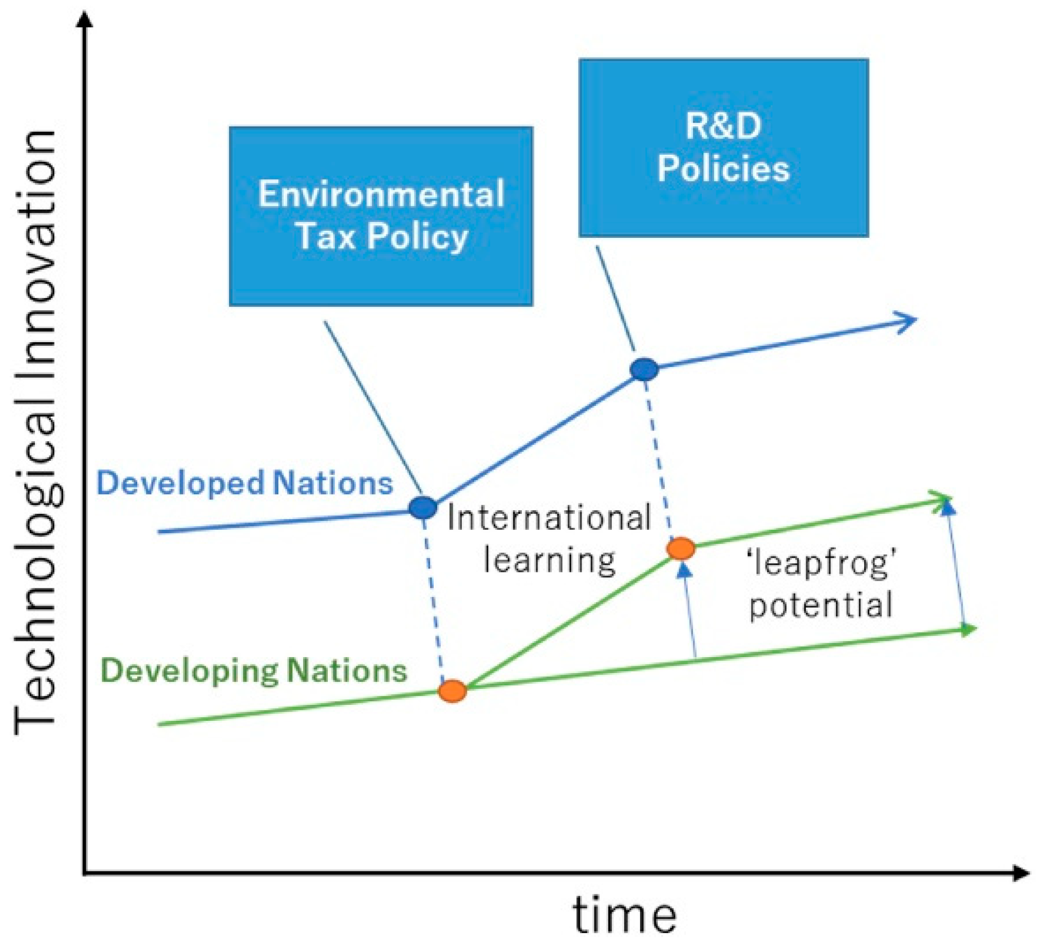
1. Introduction
2. Ammonia Fuel Combustion Characteristics
2.1. Advantages of Ammonia Fuel Combustion
2.2. Challenges in Ammonia Fuel Combustion
3. Fundamental Research on Ammonia Fuel Combustion
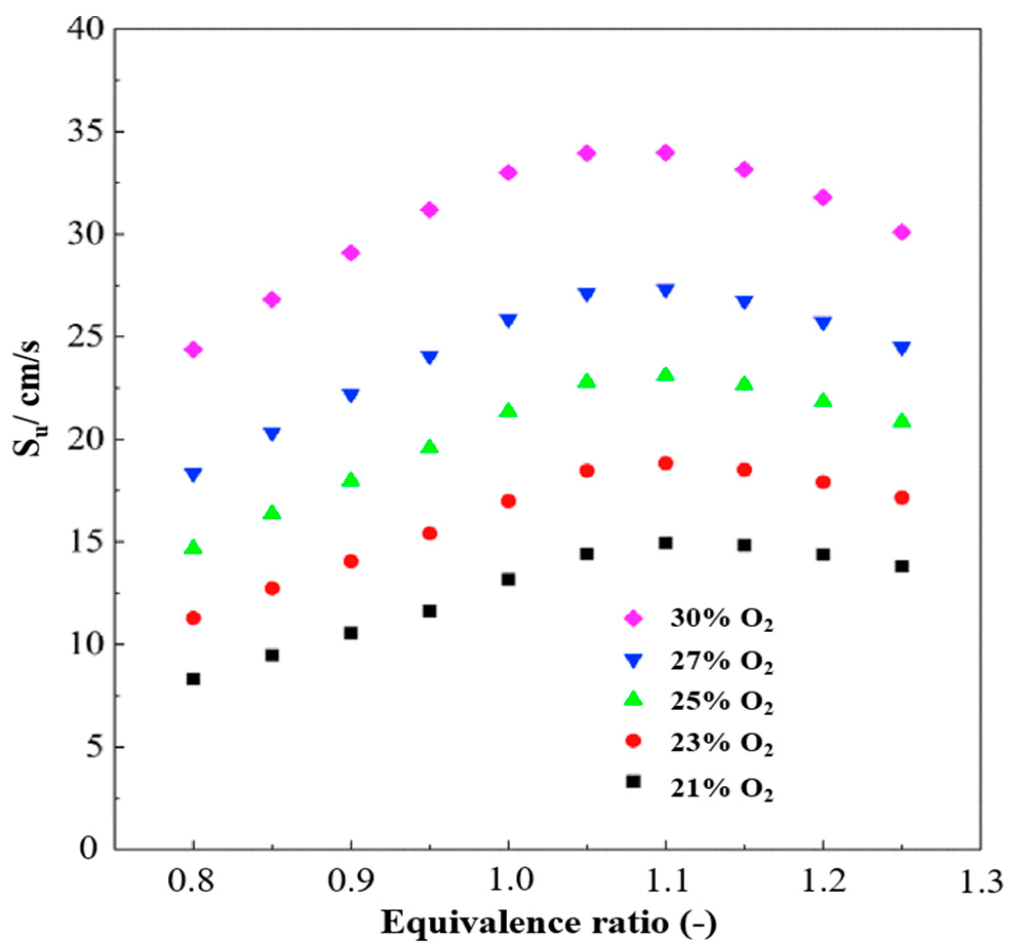
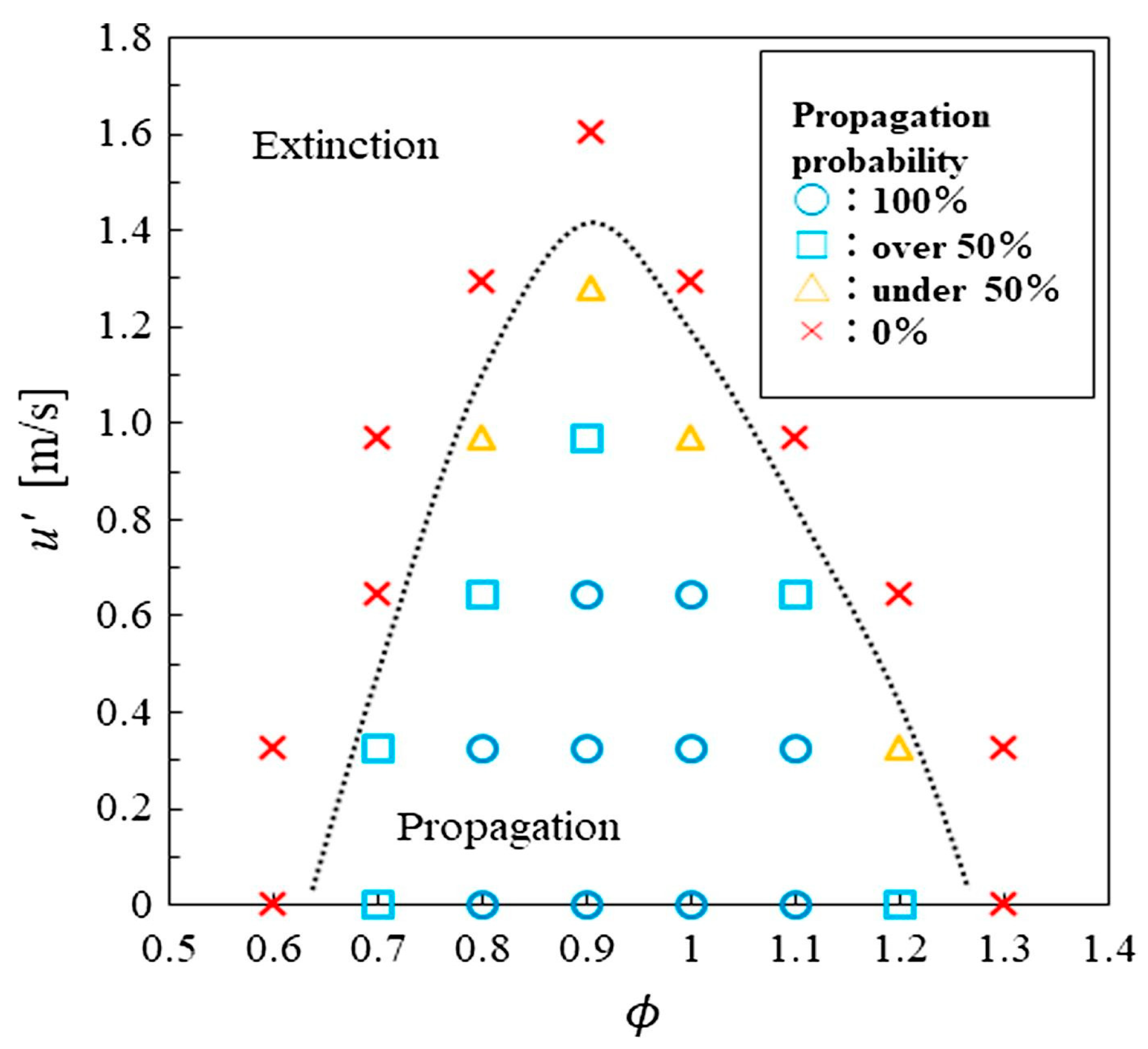
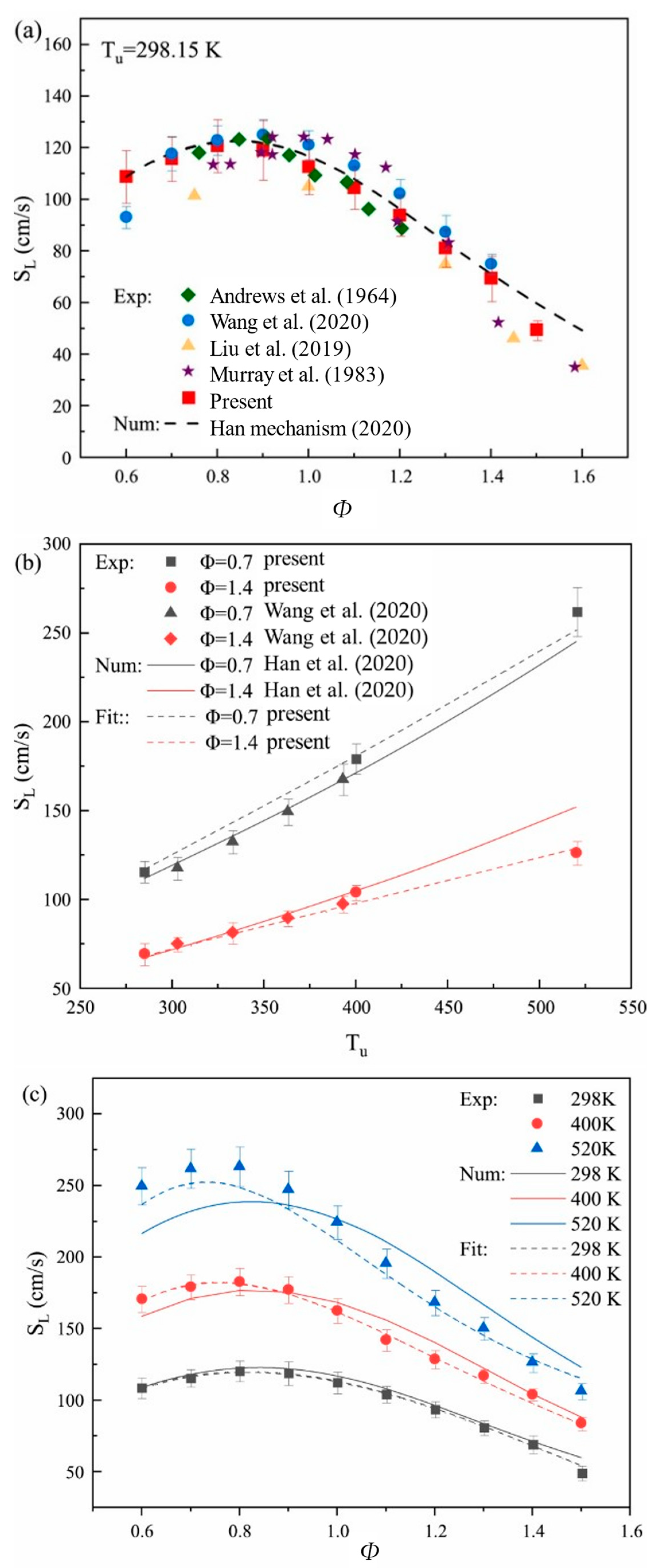
3.1. Experimental Studies
3.2. Numerical Study

| Authors | Research Method | Combustion Conditions | Approach (Injector Equipment, Methods, etc.) | Key Findings |
|---|---|---|---|---|
| Ichimura et al. [66] | Experiment |
|
|
|
| Karan et al. [67] | Experiment and simulation |
|
|
|
| Mei et al. [68] | Experiment and simulation |
|
|
|
| Zhang et al. [69] | Experiment and simulation |
|
|
|
| Okafor et al. [70] | Experiment and simulation |
|
|
|
| Liu et al. [71] | Experiment and simulation |
|
|
|
| Li et al. [72] | Experiment and simulation |
|
|
|
| Li et al. [73] | Experiment |
|
|
|
| Shi et al. [74] | Experiment and simulation |
|
|
|
| Barbas et al. [75] | Experiment and simulation |
|
|
|
| Wu et al. [76] | Simulation |
|
|
|
4. Ammonia Oxy-Fuel Combustion in Various Applications
4.1. Ammonia Oxy-Fuel Combustion in Gas-Fired Furnaces
| Authors | Research Method | Combustion Conditions | Approach Equipment | Key Findings |
|---|---|---|---|---|
| El-Adawy and Nemitallah [77] | Computational fluid dynamics (CFD) simulation |
| Swirl gas turbine combustor |
|
| Cai et al. [78] | CFD simulation |
| Micro-planar combustor |
|
| Zhang et al. [79] | CFD simulation |
| Micro-planar combustor |
|
| Cafiero et al. [80] | Experiment |
| 20-kW semi-industrial-scale furnace |
|
| Matveevet al. [82] | Chemkin simulation |
| Perfectly stirred reactor |
|
| Matveevet al. [83] | CFD simulation |
| Radial swirl combustion chamber |
|
| Cai et al. [84] | CFD simulation |
| Micro-planar combustor with a bluff-body |
|
| Cai et al. [85] | CFD simulation |
| Micro-planar combustor with perforated plates |
|
| Bektas et al. [86] | CFD simulation |
| Two-inlet cyclone combustor |
|
| Zhao et al. [88] | CFD simulation |
| Jet flame in hot co-flow (JHC) burner |
|
| Zhao et al. [89] | CFD simulation |
| JHC burner |
|
| Zhao et al. [90] | CFD simulation |
| JHC burner |
|
| Cai and Zhao [91] | CFD simulation |
| Micro-planar combustor |
|
| Luo et al. [92] | CFD simulation |
| Segmented nozzle micro-combustor in thermophotovoltaic system |
|
| Sun et al. [93] | CFD simulation |
| Rotating detonation engine |
|
| Ilbas et al. [94] | CFD simulation |
| Swirl gas turbine combustor |
|
4.2. Ammonia Oxy-Fuel Combustion in Internal Combustion Engines
| Authors | Research Method | Combustion Conditions | Approach Equipment | Key Findings |
|---|---|---|---|---|
| Park et al. [95] | Experiment |
|
|
|
| Nonavinakere et al. [96] | Experiment and Chemkin simulation |
|
|
|
| Wang et al. [97] | Experiment |
|
|
|
| Hong et al. [98] | Experiment |
|
|
|
| Park et al. [99] | Experiment |
|
|
|
4.3. Ammonia Oxy-Fuel Combustion in Coal-Fired Furnaces
| Authors | Research Method | Combustion Conditions | Approach Equipment | Key Findings |
|---|---|---|---|---|
| Zare Ghadi et al. [102] | CFD simulation |
|
|
|
| Pan et al. [103] | Experiment and CFD-DEM simulation |
|
|
|
| Zheng et al. [104] | Quantum chemistry calculations |
|
|
|
| Chen et al. [105] | Experiment and quantum chemistry calculations |
|
|
|
| Lei et al. [106] | Experiment and ReaxFF MD simulation |
|
|
|
| Xia et al. [107] | Experiment |
|
|
|
5. Conclusions
Author Contributions
Funding
Conflicts of Interest
Abbreviations
| BTE | Brake thermal efficiency |
| CFD | Computational fluid dynamics |
| DME | Dimethyl ether |
| GHG | Greenhouse gas |
| HB | Haber–Bosch |
| ICE | Internal combustion engine |
| JHC | Jet-flame in hot co-flow |
| LBV | Laminar burning velocity |
| MILD | Moderate or intense low-oxygen dilution |
| NOx | Nitrogen oxide |
| OWMT | Outer wall mean temperature |
| OWT | Outer wall temperature |
| RE | Radiation efficiency |
| SCR | Selective catalytic reduction |
| SI | Spark ignition |
| WTC | Wall thermal conductivity |
References
- National Academies of Sciences, Engineering, and Medicine. Greenhouse Gas Emissions Information for Decision Making: A Framework Going Forward; The National Academies Press: Washington, DC, USA, 2022. [Google Scholar] [CrossRef]
- Jang, B.; Oh, C.; Ahn, S.; Kim, Y.; Park, J.; Choi, M.; Sung, Y. Nitric oxide emission reduction and thermal characteristics of fuel-pulsed oscillating combustion in an industrial burner system. Energy 2021, 216, 119263. [Google Scholar] [CrossRef]
- United Nations. UN Sustainable Development Goals. 2024. Available online: https://www.un.org/sustainabledevelopment/sustainable-development-goals/ (accessed on 21 October 2024).
- Otomo, J.; Koshi, M.; Mitsumori, T.; Iwasaki, H.; Yamada, K. Chemical kinetic modeling of ammonia oxidation with improved reaction mechanism for ammonia/air and ammonia/hydrogen/air combustion. Int. J. Hydrogen Energy 2018, 43, 3004–3014. [Google Scholar] [CrossRef]
- United Nations. The Paris Agreement. 2015. Available online: https://unfccc.int/documents/184656 (accessed on 21 October 2024).
- World Bank. State and Trends of Carbon Pricing 2023. 2023. Available online: http://hdl.handle.net/10986/39796 (accessed on 21 October 2024).
- Metcalf, G.E.; Stock, J.H. The macroeconomic impact of Europe’s carbon taxes. Am. Econ. J. Macroecon. 2023, 15, 265–286. [Google Scholar] [CrossRef]
- Karmaker, S.C.; Hosan, S.; Chapman, A.J.; Saha, B.B. The role of environmental taxes on technological innovation. Energy 2021, 232, 121052. [Google Scholar] [CrossRef]
- Liu, J.; Huang, Z.; Fan, M.; Yang, J.; Xiao, J.; Wang, Y. Future energy infrastructure, energy platform and energy storage. Nano Energy 2022, 104, 107915. [Google Scholar] [CrossRef]
- Yu, Z.; Jianquan, L.; Jie, W.; Wenlong, Z. 9E heavy-duty gas turbine ammonia-hydrogen mixture combustion characteristics and NOx emission characteristics research. Int. J. Hydrogen Energy 2024, 87, 997–1010. [Google Scholar] [CrossRef]
- Feng, Z.; Pan, J.; Li, P.; Fan, B.; Nauman, M.; Yang, W. Numeral study of the mixture formation and combustion process of an ammonia/hydrogen rotary engine. Int. J. Hydrogen Energy 2024, 69, 1469–1480. [Google Scholar] [CrossRef]
- Jamrozik, A.; Tutak, W. The impact of ammonia and hydrogen additives on the combustion characteristics, performance, stability and emissions of an industrial DF diesel engine. Appl. Therm. Eng. 2024, 257, 124189. [Google Scholar] [CrossRef]
- Zhao, H. The role of green ammonia in meeting challenges towards a sustainable development in China. Energy 2024, 310, 133283. [Google Scholar] [CrossRef]
- Kobayashi, H.; Hayakawa, A.; Somarathne, K.D.; Okafor, E.C. Science and technology of ammonia combustion. Proc. Combust. Inst. 2019, 37, 109–133. [Google Scholar] [CrossRef]
- Ong, C.W.; Chang, N.; Tsai, M.L.; Chen, C.L. Decarbonizing the energy supply chain: Ammonia as an energy carrier for renewable power systems. Fuel 2024, 360, 130627. [Google Scholar] [CrossRef]
- Miura, D.; Tezuka, T. A comparative study of ammonia energy systems as a future energy carrier, with particular reference to vehicle use in Japan. Energy 2014, 68, 428–436. [Google Scholar] [CrossRef]
- Gu, T.; Araya, S.S.; Yin, C.; Liso, V. Exploring decentralized ammonia synthesis for hydrogen storage and transport: A comprehensive CFD investigation with experimental validation and parametric study. Energy Convers. Manag. 2023, 295, 117604. [Google Scholar] [CrossRef]
- IRENA; AEA. Innovation Outlook: Renewable Ammonia; International Renewable Energy Agency: Abu Dhabi, United Arab Emirates; Ammonia Energy Association: Brooklyn, NY, USA, 2022; ISBN 978-92-9260-423-3. Available online: https://www.irena.org/publications/2022/May/Innovation-Outlook-Renewable-Ammonia (accessed on 21 October 2024).
- Zhao, Z.; Zhang, M.; Wu, Y.; Song, W.; Yan, J.; Qi, X.; Yang, J.; Zhang, H. Ammonia energy: Synthesis and utilization. Ind. Eng. Chem. Res. 2024, 63, 8003–8024. [Google Scholar] [CrossRef]
- IEA. Net Zero Roadmap: A Global Pathway to Keep the 1.5 °C Goal in Reach. 2023. Available online: http://www.iea.org (accessed on 25 October 2024).
- Subramani, A.K.; Duraisamy, G.; Govindan, N.; Hossain, A.K. An innovative method of ammonia use in a light-duty automotive diesel engine to enhance diesel combustion, performance, and emissions. Int. J. Hydrogen Energy 2024, 49, 38–58. [Google Scholar] [CrossRef]
- Xu, J.; Zhao, R.; Sun, S.; Wu, Z.; Lu, Z.; Xiao, L.; Hou, L. Enhancement of ammonia corrosion resistance of coatings through improving dispersion and binding site of graphene oxide in silane coatings. J. Alloys Compd. 2024, 989, 174174. [Google Scholar] [CrossRef]
- An, T.; Wei, B.; Ma, R.; Chen, L.; Wang, S.; Xu, M.; Liu, K. Study on the high-temperature corrosion mechanism of boiler steel 15CrMoG in ammonia-coal co-firing environment. Fuel 2024, 378, 132892. [Google Scholar] [CrossRef]
- Tian, J.; Wang, L.; Xiong, Y.; Wang, Y.; Yin, W.; Tian, G.; Wang, Z.; Cheng, Y.; Ji, S. Enhancing combustion efficiency and reducing nitrogen oxide emissions from ammonia combustion: A comprehensive review. Process Saf. Environ. Prot. 2024, 183, 514–543. [Google Scholar] [CrossRef]
- Liang, W.; Law, C.K. Enhancing ammonia combustion using reactivity stratification with hydrogen addition. Proc. Combust. Inst. 2023, 39, 4419–4426. [Google Scholar] [CrossRef]
- Li, J.; Huang, H.; Kobayashi, N.; He, Z.; Osaka, Y.; Zeng, T. Numerical study on effect of oxygen content in combustion air on ammonia combustion. Energy 2015, 93, 2053–2068. [Google Scholar] [CrossRef]
- Fan, G.; Chen, M.; Wang, C.; Feng, Q.; Sun, Y.; Xu, J.; Du, Y.; Che, D. Numerical study on oxy-fuel combustion characteristics of industrial furnace firing coking dry gas. Energy 2024, 286, 129643. [Google Scholar] [CrossRef]
- Zhang, Y.; Xin, Y.; Si, M.; Liu, F.; Lou, C. Experimental study on soot formation and primary particle size in oxy-combustion ethylene diffusion flames under CO2 substitution for N2. Case Stud. Therm. Eng. 2023, 48, 103060. [Google Scholar] [CrossRef]
- Wachter, P.; Gaber, C.; Demuth, M.; Hochenauer, C. Towards a recuperative, stationary operated thermochemical reformer: Experimental investigations on the methane conversion and waste heat recovery. Appl. Therm. Eng. 2021, 183, 116121. [Google Scholar] [CrossRef]
- Gan, Z.; Yang, S.; Wang, H. Investigation of the heating characteristics of turbulent non-premixed gas combustion in the industrial-scale walking beam type reheating furnace. Appl. Therm. Eng. 2024, 257, 124212. [Google Scholar] [CrossRef]
- Li, Z.; Zhang, Y.; Zhang, H. Kinetics modeling of NO emission of oxygen-enriched and rich-lean-staged ammonia combustion under gas turbine conditions. Fuel 2023, 355, 129509. [Google Scholar] [CrossRef]
- Sun, J.; Zhao, N.; Zheng, H. A comprehensive review of ammonia combustion: Fundamental characteristics, chemical kinetics, and applications in energy systems. Fuel 2025, 394, 135135. [Google Scholar] [CrossRef]
- Valera-Medina, A.; Vigueras-Zuniga, M.; Shi, H.; Mashruk, S.; Alnajideen, M.; Alnasif, A.; Davies, J.; Wang, Y.; Zhu, X.; Yang, W.; et al. Ammonia combustion in furnaces: A review. Int. J. Hydrogen Energy 2023, 49, 1597–1618. [Google Scholar] [CrossRef]
- Yao, N.; Chen, Y.; Wei, L.; Xu, Q.; Pan, W. Progress in CFD simulation for ammonia-fueled internal combustion engines and gas turbines. J. Energy Inst. 2025, 119, 101951. [Google Scholar] [CrossRef]
- Elbaz, A.M.; Wang, S.; Guiberti, T.F.; Roberts, W.L. Review on the recent advances on ammonia combustion from the fundamentals to the applications. Fuel Commun. 2022, 10, 100053. [Google Scholar] [CrossRef]
- Wang, Y.; Wang, X.; Zeng, W.; Wang, W.; Song, Z. Advancements in turbulent combustion of ammonia-based fuels: A review. Int. J. Hydrogen Energy 2024, 88, 1332–1355. [Google Scholar] [CrossRef]
- Kang, L.; Pan, W.; Zhang, J.; Wang, W.; Tang, C. A review on ammonia blends combustion for industrial applications. Fuel 2022, 332, 126150. [Google Scholar] [CrossRef]
- Hua, Y.; Zhang, Y.; Gao, D. Ammonia composite combustion with alcohol/ether: A systematic review from engine applications to combustion enhancement and emission mechanisms. Energy Convers. Manag. 2024, 322, 119160. [Google Scholar] [CrossRef]
- Moses, J.K.; Tivfa, T.A.; Qasem, N.A.; Alquaity, A.B. Combustion characteristics of hydrogen, ammonia, and their blends: A review. Fuel 2025, 388, 134404. [Google Scholar] [CrossRef]
- Biebl, M.; Leicher, J.; Giese, A.; Wieland, C. A comprehensive study of non-premixed combustion of ammonia and its blends: Flame stability and emission reduction. Fuel 2025, 386, 134501. [Google Scholar] [CrossRef]
- Zhang, X.; Zhao, S.; Zhang, Q.; Wang, Y.; Zhang, J. A Review of Ammonia Combustion Reaction Mechanism and Emission Reduction Strategies. Energies 2025, 18, 1707. [Google Scholar] [CrossRef]
- Zhou, L.; Zhong, L.; Liu, Z.; Wei, H. Toward highly-efficient combustion of ammonia–hydrogen engine: Prechamber turbulent jet ignition. Fuel 2023, 352, 129009. [Google Scholar] [CrossRef]
- Kojima, Y.; Yamaguchi, M. Ammonia as a hydrogen energy carrier. Int. J. Hydrogen Energy 2022, 47, 22832–22839. [Google Scholar] [CrossRef]
- Tawalbeh, M.; Murtaza, S.Z.M.; Al-Othman, A.; Alami, A.H.; Singh, K.; Olabi, A.G. Ammonia: A versatile candidate for the use in energy storage systems. Renew. Energy 2022, 194, 955–977. [Google Scholar] [CrossRef]
- Tsiklios, C.; Schneider, S.; Hermesmann, M.; Müller, T.E. Efficiency and optimal load capacity of E-fuel-based energy storage systems. Adv. Appl. Energy 2023, 10, 100140. [Google Scholar] [CrossRef]
- Li, L.; Wang, B.; Jiao, K.; Ni, M.; Du, Q.; Liu, Y.; Li, B.; Ling, G.; Wang, C. Comparative techno-economic analysis of large-scale renewable energy storage technologies. Energy AI 2023, 14, 100282. [Google Scholar] [CrossRef]
- Bicer, Y.; Dincer, I. Environmental impact categories of hydrogen and ammonia driven transoceanic maritime vehicles: A comparative evaluation. Int. J. Hydrogen Energy 2018, 43, 4583–4596. [Google Scholar] [CrossRef]
- Guo, Q.; Liu, J.; Zhang, L.; Feng, X.; Wang, H. Explosion limits of binary mixtures of ammonia and additives (hydrogen, natural gas, and diethyl ether). Fuel 2025, 381, 133519. [Google Scholar] [CrossRef]
- Reiter, A.J.; Kong, S.-C. Demonstration of compression-ignition engine combustion using ammonia in reducing greenhouse gas emissions. Energy Fuels 2008, 22, 2963–2971. [Google Scholar] [CrossRef]
- Liu, J.; Liu, J. Experimental investigation of the effect of ammonia substitution ratio on an ammonia-diesel dual-fuel engine performance. J. Clean. Prod. 2024, 434, 140274. [Google Scholar] [CrossRef]
- Chatterjee, S.; Parsapur, R.K.; Huang, K.-W. Limitations of ammonia as a hydrogen energy carrier for the transportation sector. ACS Energy Lett. 2021, 6, 4390–4394. [Google Scholar] [CrossRef]
- Wakasugi, T.; Tsuru, D.; Hatta, N.; Hattori, N.; Haruna, S.; Tashima, H.; Watanabe, H. Characteristics of high-pressure spray combustion of liquid ammonia blended with methanol/propane in a marine engine. Fuel 2025, 391, 134808. [Google Scholar] [CrossRef]
- National Institute of Standards and Technology, NIST. Chemistry WebBook, Thermophysical Properties of Fluid Systems, SRD 69. Available online: https://webbook.nist.gov/chemistry/fluid/ (accessed on 11 November 2024).
- Valera-Medina, A.; Xiao, H.; Owen-Jones, M.; David, W.I.F.; Bowen, P.J. Ammonia for power. Prog. Energy Combust. Sci. 2018, 69, 63–102. [Google Scholar] [CrossRef]
- Zhang, R.; Liu, W.; Zhang, Q.; Qi, Y.; Wang, Z. Auto-ignition and knocking combustion characteristics of iso-octane-ammonia fuel blends in a rapid compression machine. Fuel 2023, 352, 129088. [Google Scholar] [CrossRef]
- Trotta, L.; Bernardini, V.; Ermini, M.V.; Campana, L.G.; Verna, M.; Raimondi, G.; Spazzafumo, G. Climate finance-driven feasibility study of a green ammonia and urea production plant in Italy. Int. J. Hydrogen Energy, 2024; in press. [Google Scholar] [CrossRef]
- Hatzell, M.C. The colors of ammonia. ACS Energy Lett. 2024, 9, 2920–2921. [Google Scholar] [CrossRef]
- Mayer, P.; Ramirez, A.; Pezzella, G.; Winter, B.; Sarathy, S.M.; Gascon, J.; Bardow, A. Blue and green ammonia production: A techno-economic and life cycle assessment perspective. iScience 2023, 26, 107389. [Google Scholar] [CrossRef]
- Zincir, B. Environmental and economic evaluation of ammonia as a fuel for short-sea shipping: A case study. Int. J. Hydrogen Energy 2022, 47, 18148–18168. [Google Scholar] [CrossRef]
- Campion, N.; Gutiérrez-Alvarez, R.; Bruce, J.T.F.; Münster, M. The potential role of concentrated solar power for off-grid green hydrogen and ammonia production. Renew. Energy 2024, 236, 121410. [Google Scholar] [CrossRef]
- Hu, L.; Niu, J.; Wu, W.; Zhao, Z.; Du, M.; Chen, L.; Zheng, Q.; Cao, H. Quantitative analysis of toxicity risks in the operation of ammonia-fueled tugboats. Ocean. Eng. 2024, 310, 118759. [Google Scholar] [CrossRef]
- Mashruk, S.; Shi, H.; Mazzotta, L.; Ustun, C.E.; Aravind, B.; Meloni, R.; Alnasif, A.; Boulet, E.; Jankowski, R.; Yu, C.; et al. Perspectives on NOX emissions and impacts from ammonia combustion processes. Energy Fuels 2024, 38, 19253–19292. [Google Scholar] [CrossRef]
- Hill, S.C.; Douglas Smoot, L. Modeling of nitrogen oxides formation and destruction in combustion systems. Prog. Energy Combust. Sci. 2000, 26, 417–458. [Google Scholar] [CrossRef]
- Nozari, H.; Karabeyoğlu, A. Numerical study of combustion characteristics of ammonia as a renewable fuel and establishment of reduced reaction mechanisms. Fuel 2015, 159, 223–233. [Google Scholar] [CrossRef]
- Wang, B.; Wang, H.; Yang, C.; Hu, D.; Duan, B.; Wang, Y. Effect of different ammonia/methanol ratios on engine combustion and emission performance. Appl. Therm. Eng. 2024, 236, 121519. [Google Scholar] [CrossRef]
- Ichimura, R.; Hadi, K.; Hashimoto, N.; Hayakawa, A.; Kobayashi, H.; Fujita, O. Extinction limits of an ammonia/air flame propagating in a turbulent field. Fuel 2019, 246, 178–186. [Google Scholar] [CrossRef]
- Karan, A.; Dayma, G.; Chauveau, C.; Halter, F. Experimental study and numerical validation of oxy-ammonia combustion at elevated temperatures and pressures. Combust. Flame 2022, 236, 111819. [Google Scholar] [CrossRef]
- Mei, B.; Zhang, X.; Ma, S.; Cui, M.; Guo, H.; Cao, Z.; Li, Y. Experimental and kinetic modeling investigation on the laminar flame propagation of ammonia under oxygen enrichment and elevated pressure conditions. Combust. Flame 2019, 210, 236–246. [Google Scholar] [CrossRef]
- Zhang, Y.; Zhang, W.; Yu, B.; Li, X.; Zhang, L.; Zhao, Y.; Sun, S. Experimental and kinetic modeling study on laminar flame speeds and emission characteristics of oxy-ammonia premixed flames. Int. J. Hydrogen Energy 2024, 63, 857–870. [Google Scholar] [CrossRef]
- Okafor, E.C.; Naito, Y.; Colson, S.; Ichikawa, A.; Kudo, T.; Hayakawa, A.; Kobayashi, H. Experimental and numerical study of the laminar burning velocity of CH4−NH3–air premixed flames. Combust. Flame 2018, 187, 185–198. [Google Scholar] [CrossRef]
- Liu, S.; Zou, C.; Song, Y.; Cheng, S.; Lin, Q. Experimental and numerical study of laminar flame speeds of CH4/NH3 mixtures under oxy-fuel combustion. Energy 2019, 175, 250–258. [Google Scholar] [CrossRef]
- Li, R.; Zhang, Y.; Chen, X.; Wang, D.; Liu, Q.; Liu, X. Experimental study on the combustion characteristics of hydrogen/ammonia blends in oxygen. Case Stud. Therm. Eng. 2024, 60, 104732. [Google Scholar] [CrossRef]
- Li, R.; Liu, X.; Chen, X.; Zhang, Y.; Zhang, Q. Flame propagation characteristics and inherent instability in premixed carbon-free hydrogen/ammonia/oxygen combustibles. J. Chem. Thermodyn. 2024, 197, 107326. [Google Scholar] [CrossRef]
- Shi, X.; Li, W.; Zhang, J.; Fang, Q.; Zhang, Y.; Xi, Z.; Li, Y. Exploration of NH3 and NH3/DME laminar flame propagation in O2/CO2 atmosphere: Insights into NH3/CO2 interactions. Combust. Flame 2024, 260, 113245. [Google Scholar] [CrossRef]
- Barbas, M.; Costa, M.; Vranckx, S.; Fernandes, R.X. Experimental and chemical kinetic study of CO and NO formation in oxy-methane premixed laminar flames doped with NH3. Combust. Flame 2015, 162, 1294–1303. [Google Scholar] [CrossRef]
- Wu, Q.; Sun, Z.; Liu, Y.; Li, H.; Zhang, A. The characteristics and mechanism NO formation during hydroxylated fuels/NH3 oxidation in oxy-fuel atmospheres. Energy. 2024, 307, 132558. [Google Scholar] [CrossRef]
- El-Adawy, M.; Nemitallah, M. Unveiling Numerically the Impact of Inlet Mixture Composition, Temperature, and Velocity on Ammonia-Oxy Combustion for Gas Turbines. Available online: https://ssrn.com/abstract=4974910 (accessed on 20 November 2024).
- Cai, T.; Zhao, D.; Wang, B.; Li, J.; Guan, Y. NO emission and thermal performances studies on premixed ammonia-oxygen combustion in a CO2-free micro-planar combustor. Fuel 2020, 280, 118554. [Google Scholar] [CrossRef]
- Zhang, Y.; Lu, Q.; Fan, B.; Quaye, E.K.; Weng, J.; Xiao, S.; Pan, J. Effect of intake method on ammonia/oxygen non-premixed combustion in the micro combustor with dual-inlet. Fuel 2022, 317, 123504. [Google Scholar] [CrossRef]
- Cafiero, M.; Sharma, S.; Kamal, M.M.; Lubrano Lavadera, M.; Iavarone, S.; Coussement, A.; Parente, A. Enhancing pure NH3 combustion: Impacts of O2 enrichment under MILD conditions in a 20-kW semi-industrial scale furnace. Proc. Combust. Inst. 2024, 40, 105336. [Google Scholar] [CrossRef]
- Sato, D.; Davies, J.; Mazzotta, L.; Mashruk, S.; Valera-Medina, A.; Kurose, R. Effects of Reynolds number and ammonia fraction on combustion characteristics of premixed ammonia-hydrogen-air swirling flames. Proc. Combust. Inst. 2024, 40, 105283. [Google Scholar] [CrossRef]
- Matveev, I.B.; Serbin, S.I.; Wolf, K. Plasma-assisted ammonia combustion—Part 1: Possibilities of plasma combustion of ammonia in air and oxygen. IEEE Trans. Plasma Sci. 2023, 51, 1446–1450. [Google Scholar] [CrossRef]
- Matveev, I.B.; Serbin, S.I. Plasma-assisted ammonia combustion—Part 2: Combustion of ammonia in oxygen. IEEE Trans. Plasma Sci. 2023, 51, 2290–2294. [Google Scholar] [CrossRef]
- Cai, T.; Zhao, D.; Jiaqiang, E. Bluff-body effect on thermal and NOx emission characteristics in a micro-planar combustor fueled with premixed ammonia-oxygen. Chem. Eng. Process. Process Intensif. 2020, 153, 107979. [Google Scholar] [CrossRef]
- Cai, T.; Becker, S.M.; Cao, F.; Wang, B.; Tang, A.; Fu, J.; Han, L.; Sun, Y.; Zhao, D. NO emission performance assessment on a perforated plate-implemented premixed ammonia-oxygen micro-combustion system. Chem. Eng. J. 2021, 417, 128033. [Google Scholar] [CrossRef]
- Bektaş, A. Oxy- and air-ammonia premixed combustion in a two-inlet cyclone combustor. Int. J. Energy Res. 2022, 46, 13874–13888. [Google Scholar] [CrossRef]
- Davies, J.; Mashruk, S.; Sato, D.; Mazzotta, L.; Pugh, D.; Valera-Medina, A. Emissions analyses of humidified cracked ammonia swirling flames. Combust. Flame 2025, 274, 113984. [Google Scholar] [CrossRef]
- Zhao, Z.; Zhang, Z.; Zha, X.; Gao, G.; Mao, W.; Wu, F.; Luo, C.; Zhang, L. Fuel-NO formation mechanism in MILD-oxy combustion of CH4/NH3 fuel blend. Fuel 2023, 331, 125817. [Google Scholar] [CrossRef]
- Zhao, Z.; Li, X.; Zhang, Z.; Zha, X.; Chen, Y.; Gao, G.; Wu, F.; Luo, C.; Zhang, L. Combustion regimes and fuel-NO mechanism of CH4/NH3 jet diffusion flames in hot O2/CO2 co-flow. Fuel Process Technol. 2022, 229, 107173. [Google Scholar] [CrossRef]
- Zhao, Z.; Zhang, T.; Li, X.; Zhang, L.; Zhang, Z.; Chen, Y.; Wu, F.; Luo, C.; Zheng, C. NO formation mechanism of CH4/NH3 jet flames in hot co-flow under MILD-oxy condition: Effects of co-flow CO2 and H2O. Fuel 2022, 313, 123030. [Google Scholar] [CrossRef]
- Cai, T.; Zhao, D. Effects of fuel composition and wall thermal conductivity on thermal and NOx emission performances of an ammonia/hydrogen-oxygen micro-power system. Fuel Process Technol. 2020, 209, 106527. [Google Scholar] [CrossRef]
- Luo, B.; Jiaqiang, E.; Chen, J.; Zhang, F.; Ding, J. Effect of NH3/H2/O2 premixed combustion on energy conversion enhancement and NOx emission reduction of the segmented nozzle micro-combustor in thermophotovoltaic system. Renew. Energy 2024, 228, 120682. [Google Scholar] [CrossRef]
- Sun, Z.; Huang, Y.; Luan, Z.; Gao, S.; You, Y. Three-dimensional simulation of a rotating detonation engine in ammonia/hydrogen mixtures and oxygen-enriched air. Int. J. Hydrogen Energy 2023, 48, 4891–4905. [Google Scholar] [CrossRef]
- Ilbas, M.; Kumuk, O.; Karyeyen, S. Numerical study of a swirl gas turbine combustor for turbulent air and oxy-combustion of ammonia/kerosene fuels. Fuel 2021, 304, 121359. [Google Scholar] [CrossRef]
- Park, C.; Jang, I.; Park, G.; Min, C.; Kim, M.; Kim, Y.; Choi, Y. Effect of oxygen concentrations in intake air on combustion characteristics of ammonia direct injection SI engine. Fuel 2024, 376, 132643. [Google Scholar] [CrossRef]
- Nonavinakere Vinod, K.; Fang, T. Experimental characterization of spark ignited ammonia combustion under elevated oxygen concentrations. Proc. Combust. Inst. 2023, 39, 4319–4326. [Google Scholar] [CrossRef]
- Wang, Z.; Ji, C.; Wang, D.; Zhang, T.; Wang, S.; Yang, H.; Zhai, Y.; Wang, H. Experimental investigation on combustion characteristics of ammonia/air using turbulent jet ignition with auxiliary oxygen in pre-chamber. Appl. Therm. Eng. 2024, 243, 122622. [Google Scholar] [CrossRef]
- Hong, C.; Ji, C.; Wang, S.; Xin, G.; Qiang, Y.; Yang, J. Evaluation of hydrogen injection and oxygen enrichment strategies in an ammonia-hydrogen dual-fuel engine under high compression ratio. Fuel 2023, 354, 129244. [Google Scholar] [CrossRef]
- Park, C.; Choi, Y.; Park, G.; Jang, I.; Kim, M.; Kim, Y.; Choi, Y. Investigation on the reduction in unburned ammonia and nitrogen oxide emissions from ammonia direct injection SI engine by using SCR after-treatment system. Heliyon 2024, 10, e37684. [Google Scholar] [CrossRef]
- Uddeen, K.; Tang, Q.; Shi, H.; Turner, J.W. Ammonia-methanol and ammonia-ethanol dual-fuel combustion in an optical spark-ignition engine: A multiple flame generation approach. Appl. Therm. Eng. 2025, 265, 125544. [Google Scholar] [CrossRef]
- Zhang, Q.; Zhang, R.; Qi, Y.; Wang, Z. Ignition characteristics of ammonia–methanol blended fuel in a rapid compression machine. Fuel 2024, 368, 131636. [Google Scholar] [CrossRef]
- Zare Ghadi, A.; Gu, B.; Lim, H. CFD analysis on the effect of ammonia addition on oxyfuel coal combustion in a swirl burner. Energy Fuels 2024, 38, 19798–19813. [Google Scholar] [CrossRef]
- Pan, S.; Ma, J.; Chen, X.; Liang, C. Combustion of an ammonia bubble with an oxygen bubble in a fluidized bed. Appl. Therm. Eng. 2024, 244, 122591. [Google Scholar] [CrossRef]
- Zheng, Z.; Shen, J.; Han, Z.; Chen, Y.; Bai, Y. Unveiling the role of oxygen in ammonia coal combustion: A DFT study on NOx emission mechanism. Comput. Theor. Chem. 2024, 1241, 114893. [Google Scholar] [CrossRef]
- Chen, P.; Wang, H.; Qiao, L.; Gu, M.; Luo, K.; Fan, J. Study of the NO formation characteristics and ammonia-N/coal-N transformation mechanism of ammonia-coal co-combustion in O2/CO2 atmosphere. Combust. Flame 2024, 270, 113756. [Google Scholar] [CrossRef]
- Lei, M.; Zhao, Z.; Hong, D.; Zeng, Y.; Tian, X.; Zhang, L.; Zhang, Q. Experimental study and molecular dynamics simulation on co-combustion of pulverized coal and NH3 at O2/N2 and O2/CO2 atmospheres. Fuel 2024, 364, 131043. [Google Scholar] [CrossRef]
- Xia, Y.; Hadi, K.; Hashimoto, G.; Hashimoto, N.; Fujita, O. Effect of ammonia/oxygen/nitrogen equivalence ratio on spherical turbulent flame propagation of pulverized coal/ammonia co-combustion. Proc. Combust. Inst. 2021, 38, 4043–4052. [Google Scholar] [CrossRef]


| Property | Ammonia | Hydrogen | Propane | Methane |
|---|---|---|---|---|
| Chemical formula | NH3 | H2 | C3H8 | CH4 |
| Octane number | 130 | – | 111 | 120 |
| Density (kg/m3) | 0.73 | 0.09 | 2.01 | 0.66 |
| Molar mass (g/mol) | 17.03 | 2.016 | 44.096 | 16.04 |
| Boiling point (°C) | −33.4 | −253 | −42.1 | −161 |
| Adiabatic flame temperature (°C) | 1800 | 2110 | 2000 | 1950 |
| Flashpoint (°C) | 132 | −253 | −104 | −188 |
| Auto-ignition temperature (°C) | 650 | 520 | 450 | 630 |
| Critical pressure (MPa) | 11.3 | 1.29 | 4.25 | 4.6 |
| Critical temperature (°C) | 132.4 | −240.21 | 96.9 | −82.59 |
| Lower heating value (LHV) (MJ/kg) | 18.6 | 120 | 50 | 46.4 |
| Higher heating value (HHV) (MJ/kg) | 22.5 | 141.9 | 50.4 | 55.5 |
| Explosive limits in air (%) | 15–28 | 4–75 | 2.37–9.5 | 4.4–17 |
| Minimum ignition energy (mJ) | 8 | 0.011 | 0.26 | 0.28 |
| Maximum laminar burning velocity (m/s) | 0.07 | 2.91 | 0.43 | 0.37 |
| Gravimetric hydrogen density (wt%) | 17.8 | 100 | 18.2 | 25 |
| Flammability limit (equivalence ratio) | 0.63–1.40 | 0.10–7.1 | 0.51–2.5 | 0.50–1.7 |
Disclaimer/Publisher’s Note: The statements, opinions and data contained in all publications are solely those of the individual author(s) and contributor(s) and not of MDPI and/or the editor(s). MDPI and/or the editor(s) disclaim responsibility for any injury to people or property resulting from any ideas, methods, instructions or products referred to in the content. |
© 2025 by the authors. Licensee MDPI, Basel, Switzerland. This article is an open access article distributed under the terms and conditions of the Creative Commons Attribution (CC BY) license (https://creativecommons.org/licenses/by/4.0/).
Share and Cite
Dwi, N.; Ischia, K.; Sung, Y. Review of Ammonia Oxy-Combustion Technologies: Fundamental Research and Its Various Applications. Energies 2025, 18, 2252. https://doi.org/10.3390/en18092252
Dwi N, Ischia K, Sung Y. Review of Ammonia Oxy-Combustion Technologies: Fundamental Research and Its Various Applications. Energies. 2025; 18(9):2252. https://doi.org/10.3390/en18092252
Chicago/Turabian StyleDwi, Novianti, Kurniawati Ischia, and Yonmo Sung. 2025. "Review of Ammonia Oxy-Combustion Technologies: Fundamental Research and Its Various Applications" Energies 18, no. 9: 2252. https://doi.org/10.3390/en18092252
APA StyleDwi, N., Ischia, K., & Sung, Y. (2025). Review of Ammonia Oxy-Combustion Technologies: Fundamental Research and Its Various Applications. Energies, 18(9), 2252. https://doi.org/10.3390/en18092252