1. Introduction
Energy storage systems (ESSs) are essential for stable electricity generation, transmission, and distribution across power plants, substations, and households [
1,
2,
3]. With the global push for renewable energy adoption, the demand for lithium-ion battery (LIB)-based ESS has surged significantly [
4,
5,
6,
7,
8]. Despite their benefits, the global installed ESS capacity accounts for only 1.8% of the required 130 GWh, primarily due to the safety concerns [
9,
10,
11]. For instance, the Republic of Korea, which has deployed around 10 GWh of ESSs since 2014, has reported over 50 fire incidents, equating to 10% of its total ESS capacity [
12,
13,
14]. Alarmingly, the causes of these fires remain unclear [
15,
16].
The high fire incidence stems from the inherent instability of LIBs, which utilize lithium-based chemistries and are densely packed in ESSs [
2]. Thermal runaway in a single cell can rapidly propagate, leading to the destruction of the entire ESS [
17,
18,
19]. Existing fire suppression technologies, including gaseous suppression agents (e.g., Novec 1230) and dry chemicals (e.g., ABC powder), attempt to control fires through suffocation, chemical reaction, or cooling [
9,
20,
21,
22]. However, these approaches have notable limitations: (1) they require large time and amounts of fire suppression agents to be effective, (2) they are ineffective in preventing thermal propagation between cells, and (3) they cannot provide continuous cooling to stabilize overheated cells [
9,
21,
23,
24,
25,
26,
27,
28,
29,
30]. Despite these limitations, conventional fire suppression systems are mandatory for ESSs exceeding 1000 kWh, whereas smaller systems (~10 kWh) often lack basic fire prevention measures, increasing fire risks [
31,
32,
33,
34,
35].
Due to the limitations of conventional fire suppression technologies, recent research has investigated alternative methods. One promising approach involves immersing batteries in fire-suppressing agents [
36,
37,
38,
39,
40]. This approach provides two primary advantages: (1) enhanced thermal management by dissipating excess heat and (2) effective fire suppression by ensuring direct contact of extinguishing agents with overheated cells. However, practical implementation has been hindered by concerns related to liquid corrosion, electrical conductivity, toxicity, compatibility, and limited agent option with current ESS designs [
36,
37,
38,
39,
40].
To address these challenges, this study proposes a liquid-immersed battery (LImB) ESS that enhances both fire safety and thermal management. By employing a specialized sealed enclosure and a fire suppression liquid agent, our approach overcomes the limitations of previous immersion-based fire suppression methods [
17,
18]. The effectiveness of this concept and system has been systematically validated at the cell and module levels [
17,
18], demonstrating immersion safety, long-term stability, effective thermal management, and fire suppression capabilities through various laboratory-scale and real-world application tests. In this paper, the LImB ESSs are tested and validated in the independent energy station.
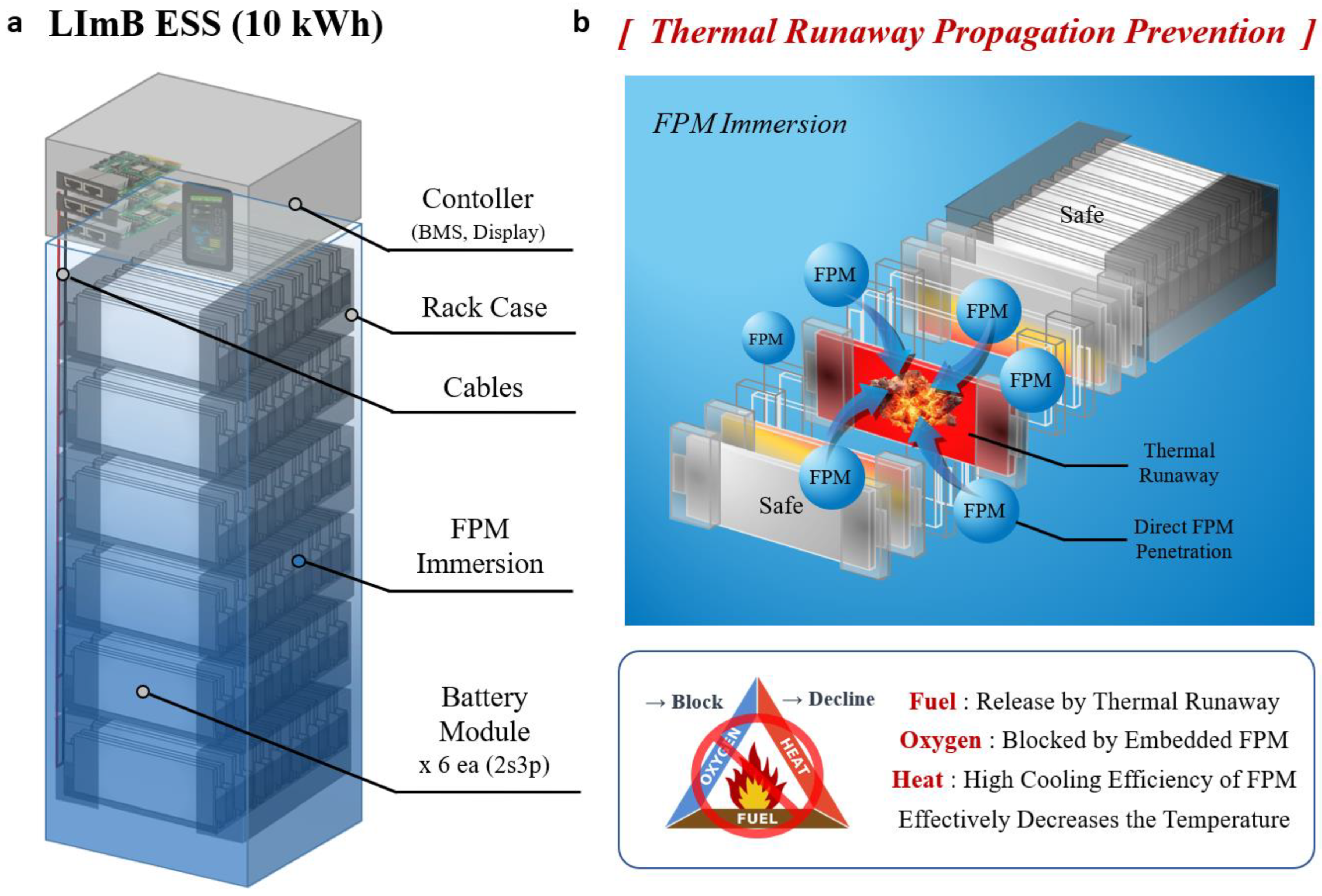
Figure 1a illustrates the structure of the LImB ESS, where battery cells are fully immersed in a fire prevention material (FPM). This design allows for rapid agent penetration, as depicted in
Figure 1b, effectively preventing fire propagation. These features are key factors in evaluating the system’s fire suppression and thermal management performance in this study. In the experiment section, fire stability tests revealed that conventional LIB ESS configurations using ABC powder reached temperatures above 1300 °C, resulting in large-scale fire propagation and system destruction. In contrast, the liquid-immersed battery system limited the maximum temperature of abused cells to 498 °C, with adjacent cell temperatures remaining below 50 °C. Fire at the initiation site was extinguished within 2 s, drastically reducing fire scale and speed. Additionally, the LImB exhibited superior thermal management during normal operation, reducing temperature elevation by a factor of 6.3 compared to conventional LIBs and decreasing temperature deviations between cells from 3.4 °C to 1.5 °C. In addition, we built and installed the liquid-immersed battery ESS in a real independent energy station to test the system under real operating conditions.
Currently, there is a lack of research on small-scale ESSs, and few studies provide empirical comparisons across fire suppression and thermal management techniques [
3,
16,
41,
42,
43]. This study addresses this research gap by systematically evaluating the effectiveness of the liquid-immersed battery system under both controlled laboratory conditions and real-world operating scenarios. The findings contribute to establishing standardized guidelines for ESS safety and efficiency, paving the way for safer and more reliable energy storage technologies.
The remainder of this paper is structured as follows:
Section 2 describes the methodology and experimental setup,
Section 3 presents the experimental results and discussion, and
Section 4 concludes with key findings and future research directions.
2. Methods
2.1. LImB Components
The detailed composition and properties of the fire prevention material (FPM), theoretical calculations for the required amount, sealing materials, heat transmission, and fire suppression mechanisms along with the governing equations, are provided in the
Supplementary Materials and further elaborated upon in the literature [
17,
18].
2.2. LImB Module
The thermal management capabilities of the LImB module were pre-evaluated to compare cooling performance with air conditioners and conventional battery modules.
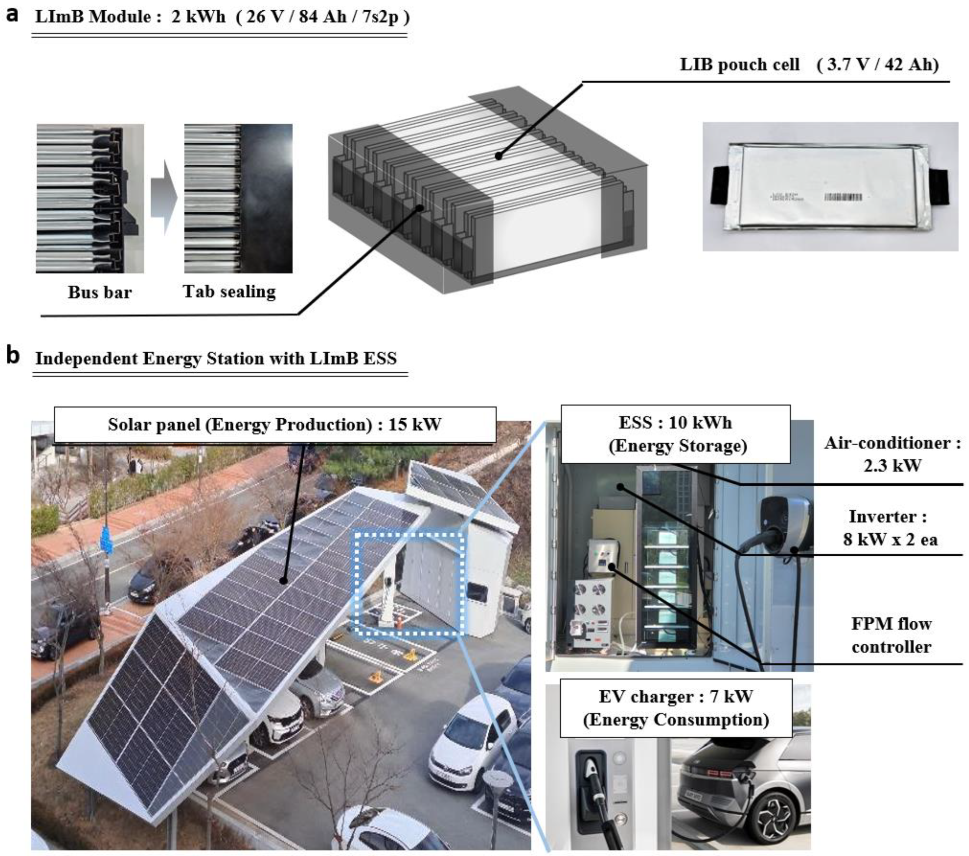
As depicted in
Figure 2a, the LImB module applied in this study for the ESS consisted of a pouch-type battery configured as 7s2p with a nominal voltage of 26 V, a capacity of 84 Ah, and an energy storage capacity of 2.175 kWh. The battery utilized was a lithium polymer pouch with a capacity of 42 Ah, designated as model LGX E42A (LG Energy Solution, Seoul, Republic of Korea). The module was immersed in approximately 3 L of FPM, corresponding to 92% of the theoretical liquid-immersion material required to suppress thermal runaway in the event of a battery fire. [
17] To mitigate risks such as short circuits and corrosion caused by contact with the liquid agent, the cell bodies, electrodes, and connections were sealed appropriately [
17,
18]. Additionally, the complete specifications of the LImB modules are summarized in
Table S1, while the specific properties of each configuration are detailed in references [
17,
18] and the
Supplementary Materials.
2.3. LImB ESS (10 kWh)
The LImB ESS, composed of LImB Modules, underwent fire-protection tests by inducing thermal runaway, and was demonstrated at an independent energy station. These experiments confirmed its fire stability and thermal management effectiveness during operation.
The LImB ESS employed in this study utilized liquid-immersed battery technology and consisted of six LImB modules, each with a capacity of 2.2 kWh (2s3p). This system had a total theoretical capacity of 13.2 kWh and an actual usable capacity of approximately 10 kWh. The LImB ESS was immersed in approximately 70 L of FPM, which is four times the theoretical amount of liquid-immersion material required to suppress thermal runaway in the event of a battery fire. [
17] Further details, including the calculation formula for the theoretical amount, are provided in references [
17,
18]. Additionally, the LImB ESS was equipped with a controller, featuring a battery thermal management system (BTMS) and a display. This setup enabled real-time monitoring of the ESS status and allowed for enhanced cooling efficiency by adjusting the flow of the liquid-immersion solution using a tank when necessary. The detailed specifications of the LImB ESS are summarized in
Table S2, while the specific properties of each configuration and composition are described in references [
17,
18] and the
Supplementary Materials.
2.4. Independent Energy Station
An off-grid energy station, as shown in
Figure 2b, is a system that generates energy from solar panels, stores the power in an ESS through an inverter, and charges the electric vehicle with stored energy as needed. It acts as an onsite station that independently conducts energy production, storage, and usage without an external power supply. On a sunny day, the power generated by the solar panels (15 kW) was charged to the ESS via two 8 kW inverters, and the stored power was used to charge approximately 7 kW of electric vehicles. The station was also equipped with a monitoring system to manage and control the entire system, a 2.3 kW air conditioner, two fire-extinguishing agent-spraying systems containing ABC powder, a DC power relay, and an FPM flow controller (Luxco, Ulsan-si, Republic of Korea). In addition, the LImB ESS was installed at the station to block the fire source and manage the heat at all times. The purpose of conducting research utilizing an independent energy station was to identify the actual thermal-management effect of the ESS unit through empirical operations under various environments and conditions, rather than a simple module. In this study, we demonstrate the superiority of LImB thermal management by comparing the temperature-increase gap between LIB/LImB/air cooling in an extreme environment where the ESS is discharged during the hottest time of summer. Additional data from smart stations with the LImB ESS can be found in
Supplementary Materials.
2.5. Thermal Runaway Transition Test Conditions
To measure the fire stability, the transfer-blocking effects of each fire-extinguishing method were compared when thermal runaway occurred. For reliability and safety, the tests were conducted in an explosion-proof chamber in a battery system laboratory under the following conditions using the current-applied equipment from the Korea Electrical Research Institute (KERI) (Changwon-si, Republic of Korea). The thermal runaway test was conducted by overcharging two parallel-connected cells with a typical ESS-charging current of 30 A (0.36 C). During the experiment, voltage and temperature at multiple points within the ESS were recorded using a data logger. Additionally, fire propagation was monitored in real-time with conventional and thermal-imaging cameras to assess suppression effectiveness. The experiments were conducted five times, and the results show a standard deviation of ±0.5 °C for temperature measurements, confirming the reliability of the data.
2.6. Thermal Management Test Conditions
To measure the thermal-management performance of the LImB, the cooling effects of each thermal-management method (LIB/LImB/air cooling) were compared when the battery was charged and discharged. For the module experiment, charging and discharging were performed with 30 A (0.36 C), which is the driving current of an energy station and conventional ESS, and the voltage of the batteries in operation and the temperature at various points were measured using a data logger to compare the cooling effect. The general LIB and LImB were operated in an environment of 30 °C, and the air cooling was conducted in an environment with convection of 2 m/s at approximately 25 °C, imitating the cooling conditions of an energy station. All experiments were conducted in a thermal-management chamber to maintain the safety and environment. For further demonstration, an ESS was built inside an off-grid energy station, and the rise of temperature inside the battery was measured using the thermal-management method when the ESS was discharged at 75.6 A, the charging current of an electric vehicle. The temperature increase was recorded separately, as the temperature increased owing to the external environment and the temperature increase caused by heat generation when the battery was discharged. Subsequently, the temperature and electrochemical information of the battery were recorded in real time using the monitoring system and temperature-measuring device installed in the ESS.
3. Results and Discussion
3.1. Fire Stability Test: LIB + ABC Powder Extinguisher/LImB (Liquid-Immersed Battery)
The purpose of this experiment was to compare the fire suppression capabilities of LIB and LImB ESSs with that of ABC powder extinguishers by determining the temperature and propagation tendency by location during battery thermal runaway. Thermal runaway was induced in two cells of a LIB module located at the center of the ESS by overcharging, and a current of 30 A (0.36 C) was applied.
The experimental setup was as follows. For the LIB ESS, an automatic fire-extinguishing diffuser device was installed on top of the module to induce overcharging. The extinguisher contained ABC powder, which has a cooling and suffocating effect, with the chemical formulas NaHCO
3 and NH
4H
2PO
4, and a built-in capacity of approximately 3 kg. This device is typically used to extinguish EVs [
44,
45] and has a nominal protection area of approximately 10 m
2, which is sufficiently applicable to a 10 kWh ESS [
46]. It automatically sprays extinguishing powder to suppress the fire when it reaches a temperature of 72 °C or higher. In the case of the LImB ESS, all battery modules were immersed in 69.84 kg of liquid agent, which allowed immediate penetration into the battery cells in the case of an emergency. In addition, abuse equipment (overcharging devices), voltage and temperature measurement lines, cameras, thermal imaging cameras, and data loggers were used.
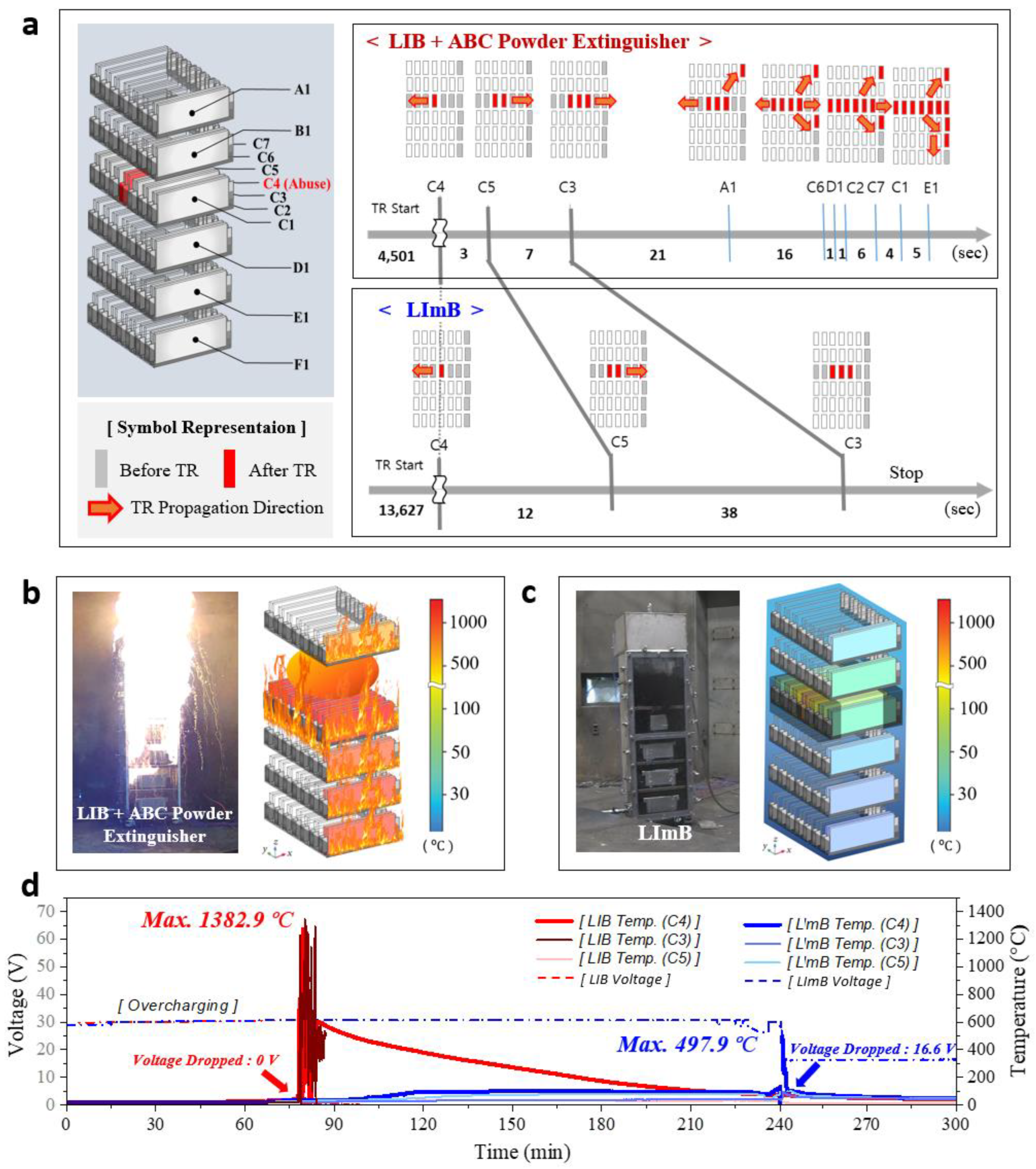
The symbols on the left side of
Figure 3a indicate the numbers and temperature measurement positions of the cells in the battery. The cells on the surface of the modules from top to bottom are labeled A1, B1, C1, D1, E1, and F1, whereas the cells in the abused cell-containing center module are labeled C1–C7. On the right, the thermal runaway transition cells and the propagation direction are marked by the time interval. In the case of the LIB with the ABC powder extinguisher, the propagation initially spread to both sides during the thermal runaway event, and the transition in the upward and downward directions started towards the end of the horizontal transition. At this time, the module suffered an explosive rate of fire propagation and the ESS burned out immediately. On the other hand, in the case of the LImB, owing to the fire suppression effect of the liquid agent, the time required for the propagation after thermal runaway was prolonged by approximately 4 times more than that of the LIB and the propagation was blocked, except for the two sides of the abused cell.
As shown in
Figure 3b, the LIB ESS with automatic fire-extinguishing diffusers suffered immediate fire spread at the onset of thermal runaway with a large explosion and sparks. There was little effect of the automatic fire-extinguishing diffuser, and most of the batteries reached temperatures above 800 °C. However, as shown in
Figure 3c, the onset of thermal runaway was delayed by the thermal management effect and the fire was immediately suppressed in the LImB ESS. Also, the duration and size of the fire were very small because of the penetration of the liquid agent. The LImB reduced thermal propagation by 75% compared to the LIB, achieving a peak temperature of 498 °C versus 1363 °C in the LIB, whereas the rest of the battery remained at room temperature. A video of the thermal runaway test is provided in the
Supplementary Materials.
As shown in
Figure 3d, for the LIB ESS, thermal runaway occurred in the abused cell approximately 78 min after the start of overcharging, and the temperature of the abused cell reached up to 1363 °C, while the voltage suddenly dropped to 0 V. The temperature remained above 400 °C for a considerable time after thermal runaway propagation and remained above 300 °C one hour after the burnout. The fire lasted 38 min and burned down the entire battery except for one cell located at the bottom of the ESS. In contrast, in the LImB, the start of thermal runaway was delayed by approximately 239 min owing to the cooling effect of the liquid-immersion agent, which was approximately three times longer than that in the comparison experiment, and the thermal runaway transition rate was reduced by more than 4 times compared to that of the LIB. The maximum temperature reached in the abused cell was 498 °C, which was approximately 2.75 times lower than that observed in the LIB. The fire was extinguished within 2 s, and the reaction with the liquid agent was observed through smoke. The abused module was damaged only on both sides of the cell to which the thermal runaway was applied, and then immediately returned to room temperature after fire extinction. Finally, the thermal runaway propagation stopped, and the module was maintained at 16.6 V. The specific mechanisms and heat transmission diagram with the governing equations of the LImB are provided in the literature [
18].
3.2. Thermal-Management Performance Comparison of Modules: LIB/Air Cooling/LImB (Liquid-Immersed Battery)
The purpose of this experiment was to identify the thermal tendency of the LIB module during operation and compare the cooling effects of air cooling and the LImB as thermal-management conditions. For this purpose, the temperature of each point in the module was measured at the end of the second discharge cycle when charging and discharging at 0.35 C under the 21 V/30 V cut-off condition.
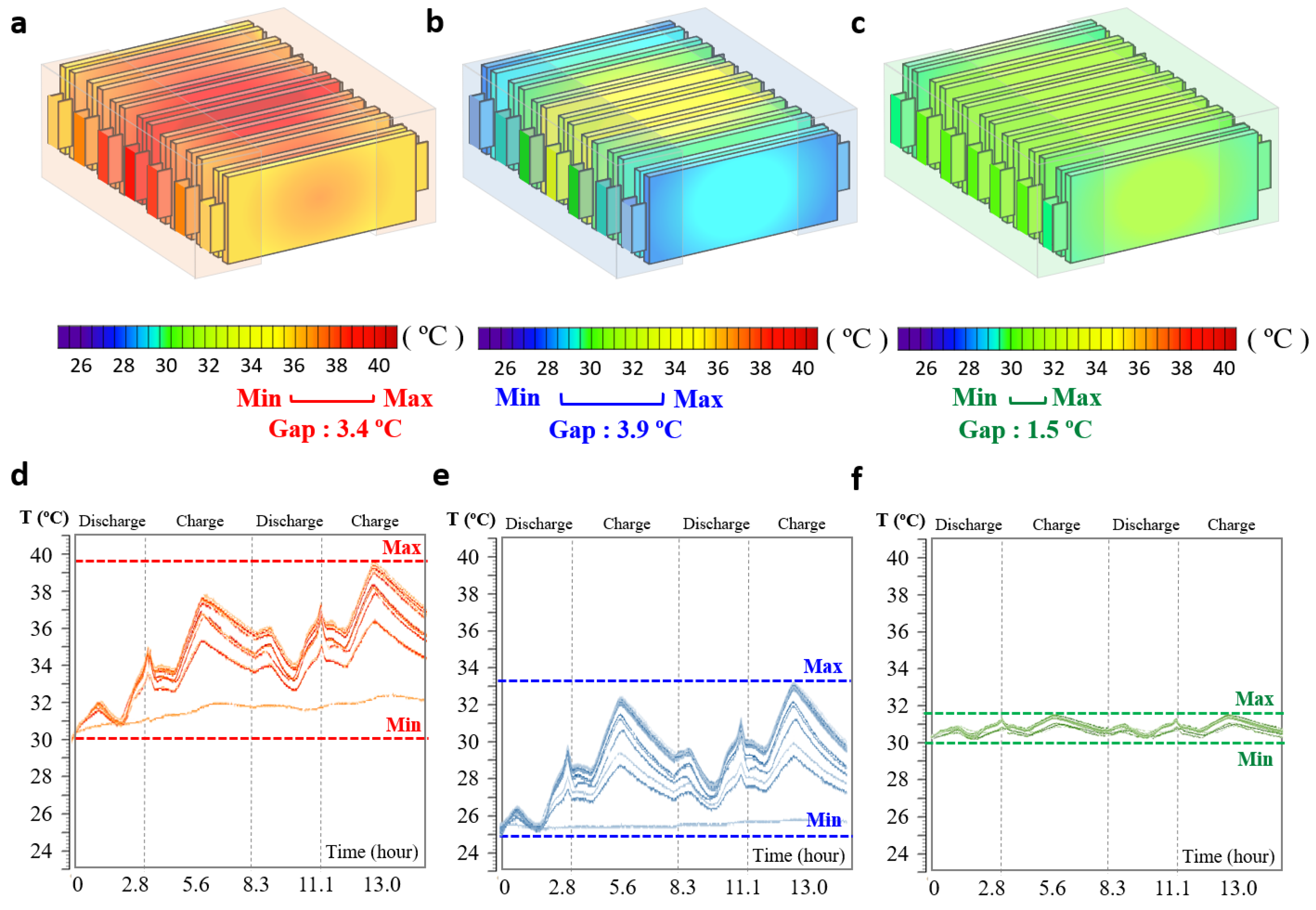
Figure 4 shows the visualized temperature of the module according to the thermal-management conditions. The LIB without air cooling (LIB) showed the highest overall temperature, whereas the LIB with air cooling and the LImB had lower overall temperatures than the LIB alone. According to
Figure 4a, in the LIB module without air cooling, the temperature of the center cell in the module increased from approximately 30 to 39.4 °C and the surface cell temperature was approximately 36.3 °C. The temperature increased by approximately 9.4 °C from the beginning of the experiment. The central cell and surface cell show a temperature deviation of approximately 3.4 °C, which can lead not only to a decrease in electrochemical performance such as capacity and cycle life, but also to overall balancing problems if the deviation is intensified. However, when running an air conditioner for air cooling, as shown in
Figure 4b, the temperature reduction effect is evident by increasing delta T owing to cooling and speeding up the heat-transfer coefficient through circulation. In other words, there is an advantage to rapid cooling, even if the air absorbing the heat generated by the battery is transferred to a high temperature. In the case of the LIB with air cooling, the temperature of the center cell in the module increased from approximately 25 to 32.2 °C, and that of the surface cell increased to approximately 29.0 °C; this was a maximum increase of only 7.2 °C from the initial temperature. However, as heat intensified and heat transfer deteriorated at the center of the module, it became difficult to manage the heat, and the temperature gap between the cells in the module reached approximately 3.9 °C, which deepened the deviation compared to the LIB module. The temperature rise could be further reduced by adjusting the set temperature and circulation coefficient of the air cooling system; however, the temperature deviation was expected to be more severe.
Figure 4c shows the LImB’s minimal temperature rise, attributed to its high heat-transfer coefficient, heat capacity, and density of FPM. The temperature of the center cell in the module increased from approximately 30 to 31.5 °C, and that of the surface cell increased to approximately 30.3 °C, with a maximum increase of only approximately 1.5 °C from the initial temperature. In particular, the deviation between cells in the module was significantly reduced to approximately 1.2 °C, which is expected to have a high balancing effect in large-scale systems.
Figure 4d–f show the battery temperatures during charging and discharging under heat-management conditions. In
Figure 4d, the LIB without air cooling, the temperature deviation in the module gradually increased over time, and the overall temperature increased. As shown in
Figure 4e, thermal management with air cooling reduced the overall temperature; however, it failed to prevent deviations or increases. In contrast, the LImB module in
Figure 4e maintained the initial temperature and prevented temperature deviations and increases. The specific mechanisms and heat transmission diagram with the governing equations of the LImB are provided in the literature [
18].
3.3. Thermal-Management Performance of ESSs: Validation of Off-Grid Energy Station
The purpose of this experiment was to compare the cooling effectiveness of air cooling and LImBs under the thermal-management conditions of a 10 kWh ESS in an independent energy station. During operation, a more detailed thermal management analysis was required compared to the module because the temperature inside the station increased owing to factors in the external environment, such as solar heat, and the temperature increased inside the battery owing to heat generation. To analyze the comparative thermal-management capabilities in extreme environments, the ESS was applied to a station and discharged at 0.3 C (rated output of an electric vehicle) during the hottest time of the summer.
The temperature increase inside the ESS by point, according to the thermal-management method, was recorded based on the time when the temperature increased the most. For these tests, data were obtained for each thermal-management condition by continuously repeating the electricity generation through solar power, power storage in the ESS, and discharge.
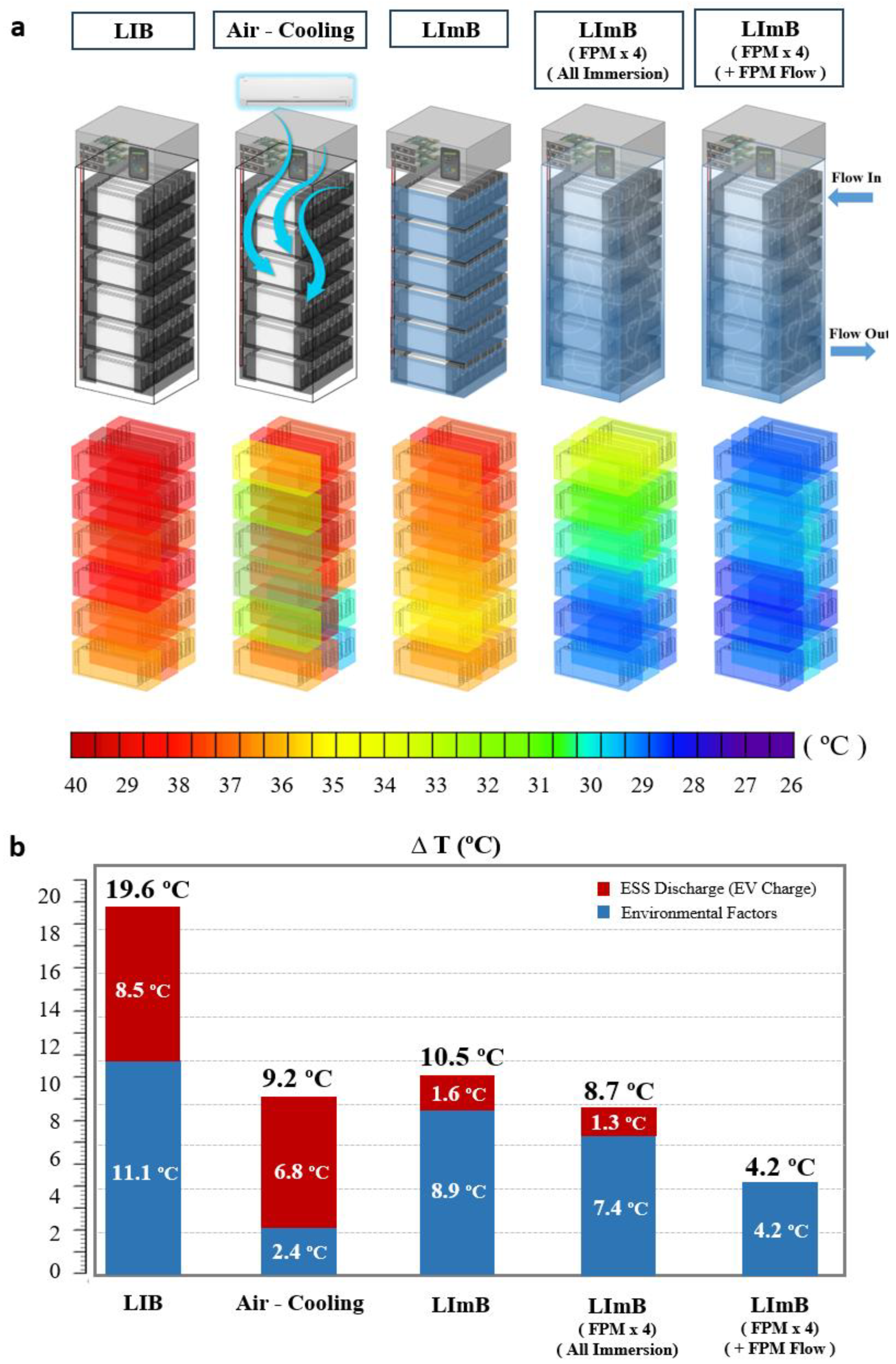
Figure 5a shows a visualization of the temperature of a 10 kWh battery located inside the ESS. In the case of the LIB, the temperature increased to approximately 40 °C overall, and as the high-temperature fluid was light in weight, the temperature was slightly higher in the upper part compared to the lower part. In the case of air cooling, the temperature was lower than that of the LIB without air cooling; however, there was no regular temperature reduction rate depending on the location. In particular, similar to the module experiment, the outer part of the module usually showed a large temperature decrease, whereas the center generally showed a high temperature increase. In the case of the LImB, the minimum temperature was higher than that of the air cooling method, but overall, the rate of temperature decrease was uniform compared to that of the LIB. By increasing the amount of liquid agent applied to the LImB by approximately four times, wherein all the modules were immersed together in the ESS, the heat-management effect was superior. The overall temperature was further reduced; however, on the bottom, it was still higher than that at the top. Lastly, the immersion agent with a flow rate of approximately 0.5 L/s had the greatest cooling effect, and the overall point-to-point temperature was cooled uniformly.
Figure 5b shows a graph that separates the temperature increase of ESSs by the thermal-management method into the temperature increase caused by the external environment, such as solar heat and sunlight, and the internal temperature increase of the cell owing to heat generation when the ESS is discharged. In the case of the LIB, not only did the temperature increase by approximately 11.1 °C due to the external environment, but the temperature also increased by approximately 8.5 °C due to the ESS discharge, resulting in a total temperature increase of 19.6 °C. In the case of air cooling through an air conditioner, the temperature increase caused by the environment was significantly reduced to approximately 2.4 °C due to the constant cooling effect. Considering the ESS discharge-led temperature rise, the temperature increased by approximately 9.2 °C, which is 2.1 times compared to running a general LIB ESS. In the case of the LImB, the external environment-led temperature rise was approximately 8.9 °C, which was not significantly low compared to that of the LIB; however, the temperature decrease due to ESS discharge was significantly reduced to 1.6 °C. In this case, the temperature reduction rate was 10.5 °C, which is about 1.9 times the temperature reduction effect of operating the general LIB ESS, but the cooling effect was almost the same as that of air cooling. In the structure where the amount of liquid agent applied to the LImB was increased by about 4 times and all modules were immersed together in the entire ESS, the temperature increase due to the external environment was approximately 7.4 °C and the temperature increase due to ESS discharge was approximately 1.3 °C, which increased the overall cooling effect. However, the temperature increase rate of approximately 8.7 °C. was not considered statistically significant. The temperature significantly decreased when flow was applied to the liquid agent. When circulating the liquid agent stored in an external tank, the external environment-led temperature increase was greatly reduced to approximately 4.2 °C because of the increased amount of immersion solution, and the heat was immediately dissipated due to the flow of the fluid; hence, there was almost no heat generation during discharge.
The loss of energy density due to the application of the LImB was also insignificant. The energy density of the module applied to the LImB ESS was approximately 162 Wh/L, which was 1.63 times less than that of a conventional LIB. Compared with lead–acid batteries, which have an energy density approximately two times lower than that of LIBs [
44], and flow batteries, which have an energy density approximately five times lower than that of LIBs [
44], they have higher space utilization. Furthermore, based on a station with a 10kWh LImB ESS, the energy density increased to 198 Wh/L, which was only 1.33 times lower than that of a conventional LIB, if management systems such as two 3 kg fire-extinguishing systems and a 2.3 kW air conditioner are excluded. Currently, the energy density of the LImB ESS is lower than that of the LIB because the flow system and other auxiliary materials are not optimized; however, it is expected that this can be compensated for by improving the LImB components or optimizing the thermal-management design through simulation.
4. Conclusions
This study demonstrates the potential of the LImB system as an innovative solution for enhancing ESS safety and thermal management. The results suggest its potential to replace conventional fire suppression systems and simplify ESS cooling infrastructure. The research was conducted in stages and examined all aspects of the system from components to efficacy. Its superior performance was validated in a 10 kWh LImB ESS.
First, if the battery is fully immersed in a high-performance liquid agent, it can significantly block fire occurrences by allowing the agent to immediately penetrate the battery when thermal runaway occurs, as opposed to conventional fire-extinguishing agents.
Second, compared to LIBs, LImBs have superior thermal-management effects; liquid-immersed batteries prevent temperature rise during operation and reduce the temperature variations between cells. This not only prevents degradation but also helps to maintain the balance between cells. One of the comparison groups, the air cooling system, while effective in preventing the temperature rise, was found to be unable to cool the battery cells uniformly, which worsened the temperature deviation compared to the general LIB.
These effects were subsequently validated at a demonstration at an energy station. When the ESS is not operating, constant management by an air conditioner has a higher cooling effect than the LImB. However, when the battery is running under extreme conditions, the LImB has a superior instantaneous cooling effect than the air conditioner.
This study demonstrated the applicability of LImBs as an ESS, and if applied, it is expected to replace existing fire-extinguishing equipment and simplify the cooling system while securing stability and increasing battery-charge rate. First and foremost, the system offers a high level of safety. By selectively disabling only the problematic cell at the onset of thermal runaway, it significantly minimizes the risk of propagation. In addition, the high specific heat capacity and thermal conductivity of the immersion fluid enable cost-effective thermal management without the need for dedicated cooling facilities or active operation, which may also contribute to extended battery lifespan. Furthermore, the immersion fluid does not contain components that generate harmful gases, making it environmentally friendly.
Future research should aim to optimize LImB components to further enhance energy density and overall system efficiency. Additionally, expanding experimental conditions across independent energy stations of varying scales will be essential to validate the scalability of LImB technology and assess its broader applicability. Also, investigating the environmental impact of FPM disposal and recycling will enhance system sustainability. With appropriate infrastructure in place, the widespread adoption of liquid-immersed batteries has the potential to revitalize the ESS market by enabling safer and more efficient energy storage solutions across various applications.


