Article

New Fault-Tolerant Sensorless Control of FPFTPM Motor Based on Hybrid Adaptive Robust Observation for Electric Agricultural Equipment Applications

1
School of Electrical and Information Engineering, Jiangsu University, Zhenjiang 212013, China
2
State Grid Zhenjiang Power Supply Company, Zhenjiang 212013, China
*
Author to whom correspondence should be addressed.
Energies 2025, 18(8), 1962; https://doi.org/10.3390/en18081962
Submission received: 14 March 2025 / Revised: 9 April 2025 / Accepted: 10 April 2025 / Published: 11 April 2025

Abstract

:
This paper proposes a hybrid adaptive robust observation (HARO)-based sensorless control strategy of a five-phase fault-tolerant permanent-magnet (FPFTPM) motor for electric agricultural equipment applications under various operating conditions, including fault conditions. Regarding fault-tolerant sensorless control, the existing studies usually treat fault-tolerant control and sensorless control as two independent units rather than a unified system, which makes the algorithm complex. In addition, under the traditional fault-tolerant algorithm, the system needs to switch after diagnosis when the fault occurs, which leads to a degraded sensorless control performance. Hence, this paper proposes a fault-tolerant sensorless control strategy that can achieve the whole speed range without fault-tolerant switching. At zero/low speed, a disturbance adaptive controller (DAC) architecture is developed by treating phase faults as system disturbances, where robust controllers and extended state observer (ESO) collaboratively suppress speed and position errors. At medium/high speeds, this paper provides a steady-healthy SMO, which combines the enhanced observer and universal phase-locked loop (PLL) without phase compensation. With above designs, the proposed strategy can significantly improve the estimated accuracy of rotor position under normal conditions and fault circumstances, while simplifying the complexity of the fault-tolerant sensorless algorithm. Furthermore, the proposed strategy is verified based on the experimental platform of the FPFTPM motor drive system. The experimental results show that compared with the traditional method, the torque ripple and position error are reduced by nearly 20% and 60%, respectively, at zero-low speed and medium-high speed, and the torque ripple is reduced by 55% during fault operation, which verifies the robustness and effectiveness of the proposed method.

1. Introduction

In recent years, under rapid agricultural mechanization, agricultural equipment has been widely used [1,2]. To meet the agricultural requirements of energy saving, efficiency, environmental protection, and green energy [3,4,5,6], the electrification and intelligence of agricultural equipment have become the focus of attention [7,8,9,10,11]. As the permanent magnet (PM) motors have the advantages of high power density, high efficiency, simple structure, and a wide speed range [12,13], they have attracted much attention in agricultural electrification [14,15,16,17]. Since the reliability of motor drive systems is directly related to the safety and stability of agricultural production, it is of crucial significance in agricultural equipment applications. However, agricultural equipment in the field needs to face heterogeneous soil properties [18,19], variable crop geometries [20,21], and other complex environments [22,23,24] prone to causing failure. This puts forward requirements for the high reliability and strong fault tolerance of the motor drive system. Compared with three-phase PM motors, the multiphase PM motors have more control degrees of freedom, which can realize fault-tolerant operation [25,26]. In [27], a five-phase fault-tolerant permanent magnet (FPFTPM) motor was proposed, and its corresponding fault-tolerant control has been investigated in [28], which can meet the reliability requirement for the agricultural equipment application. Nevertheless, conventional position-sensing methodologies relying on mechanical encoders cannot meet the high requirements of agricultural environments for position accuracy [29,30,31]. Harsh operating conditions induce severe mechanical vibrations that compromise position measurement accuracy and even lead to sensor failures and safety risks [32,33,34,35,36]. Consequently, the sensorless control technique has emerged as an essential solution to improve system reliability and reduce mechanical complexity [37].
According to different speed ranges, the sensorless control strategies are typically divided into two types. In medium/high-speed applications, the sensorless control strategy is based on the back electromotive force (EMF), with a sliding-mode observer (SMO) being widely used due to their structural simplicity and robustness [38]. Conversely, zero/low-speed operation necessitates high-frequency (HF) signal injection methods that exploit motor saliency characteristics [39], which is suitable for agricultural equipment applications [40,41]. While these methods demonstrate efficacy under normal operating conditions, their performance degrades significantly under fault states. When the FPFTPM motor system operates at the fault condition, its normal phase currents will be severely distorted. At this point, the FPFTPM motor system is in an asymmetric state, which will result in the inability to directly apply the existing traditional sensorless technology at fault operation. So, the development of the sensorless control strategy under fault conditions is significant for further improving the reliability of the motor system.
Current research on fault-tolerant sensorless control remains predominantly focused on medium/high-speed regimes [42,43,44]. In [42], the sensorless control with a flux linkage-current-angle model for the fault-tolerant PM motor system is proposed. This sensorless control strategy can be realized both in phase open-circuit (OC) and short-circuit (SC) fault conditions. However, the proposed approach is sensitive to the system parameter variation and suffers from the problems of low estimation accuracy and a high computation burden. In [43], a strong-robustness SMO with a wide speed range is proposed for the five-phase PM motor to realize sensorless fault-tolerant control under OC fault conditions. This method can greatly reduce the SMO’s chattering system and improve robustness to motor parameters, fault, and load disturbance. Yet, owing to the need of the coordinate transformation, the normal signals will be inevitably influenced by the fault signal, which will degrade estimated performance under fault conditions. In [44], the sensorless fault-tolerant control for aerospace five-phase PM motor drives with OC and SC faults is proposed, which can gain good estimated performance under fault conditions. However, because the HF chattering exists in the back-EMF observer, the variable cut-off frequency LPF and a phase delay compensation are employed, which will inevitably increase the complication of the SMO algorithm, with existing solutions suffering from parametric sensitivity, computational complexity, or compromised robustness under fault-induced asymmetries.
For the research of zero-low speed sensorless control, due to the current distortion and harmonic effects after the fault, the performance of the HF signal injection method will deteriorate significantly, or even completely lose control. Nevertheless, the current research in this area has not received enough attention, and the research almost adopts the method of suppressing harmonics after fault tolerance [45,46]. In summary, the existing sensorless control strategy under fault conditions is actually to solve the problem of fault and sensorless control as different problems. Although the HF signal injection method can operate normally, it needs to use the fault-tolerant reduced-order transformation matrices or change the hardware circuit structure. However, using the redundancy reduced-order transformation matrix under fault tolerance, the control drive system under normal and fault conditions is different, which will increase the complexity of the entire drive system. These challenges motivate the development of a unified sensorless control framework, which can maintain estimation accuracy across full-speed ranges while accommodating fault conditions without system reconfiguration.
Motivated by this, a new hybrid adaptive robust observation (HARO) sensorless control scheme is proposed for the FPFTPM motor under different operating conditions, including fault conditions. This paper presents three fundamental innovations. First, a disturbance adaptive controller (DAC) architecture for zero/low-speed operation is designed. The disturbance robust controller (DRC) and the ESO-based auto-disturbance rejection sensorless observer are designed in the speed loop and the position loop, respectively, which can actively suppress harmonic disturbances generated after the fault. Second, a steady-healthy SMO is constructed by attempting to utilize any two healthy phase back-EMFs and a hyperbolic function novel. The LPF and the extra compensator are not required any longer. Third, recent studies on fault-tolerant sensorless control, predominantly fail to unify sensorless control and fault adaptation under a single framework, leading to parameter sensitivity and algorithm reconfiguration. In contrast, this work integrates both functionalities into a unified HARO framework, eliminating algorithm reconfiguration and achieving full-speed robustness without coordinate transformations. The proposed method realizes the non-reconfigurable motor drive system after fault and the estimated accuracy under normal conditions, fault circumstances, and uncertain environments can be improved.
The rest of this article is organized as follows. The traditional sensorless control will be briefly introduced in Section 2. In Section 3, the analysis of sensorless under fault will be described. Section 4 will describe the proposed HARO strategy. The experimental results will be given to validate the proposed sensorless control strategy in Section 5. Finally, Section 6 will conclude this article.

2. Sensorless Control Methods for FPFTPM Motor Drive

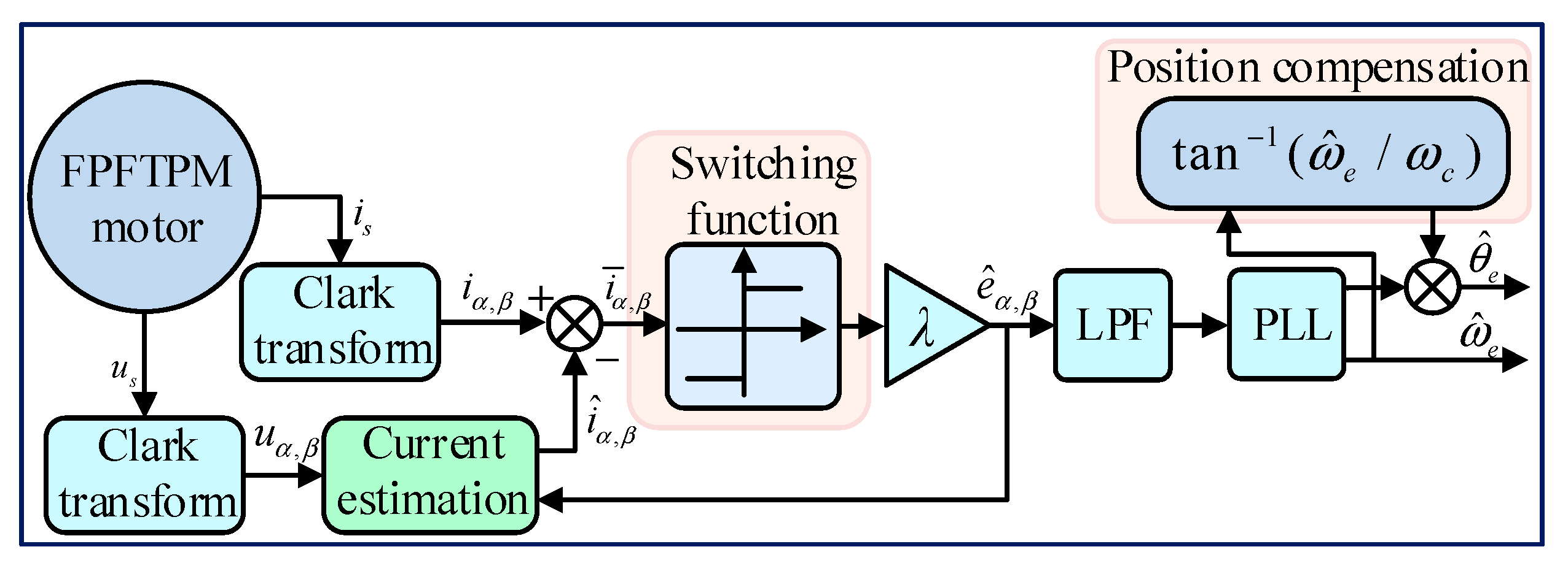
2.1. Conventional SMO-Based Sensorless Control

In the conventional SMO, the observer is constructed by using a switching function to equate the back-EMF, which is expressed as follows:
d i ^ α d t = R s L s i ^ α + 1 L s u α λ L s H ( i ¯ α ) d i ^ β d t = R s L s i ^ β + 1 L s u β λ L s H ( i ¯ β )
where i ^ α , i ^ β is the estimated stator current in the two-phase static frame (αβ-frame); uα, uβ is the stator voltage in αβ frame; Rs and Ls are the stator resistance and inductance; and i ¯ = i ^ i is the current error between the estimated current and the actual current. For the conventional SMO, H ( i ¯ α ) and H ( i ¯ β ) are signum functions; λ is the observer gain. To keep the SMO stable, the following conditions should be satisfied:
λ > m a x ( e α , e β )
where eα and eβ represent the phase back-EMF in αβ frame.
Since the switching function will introduce high-frequency disturbance in EMF estimation, LPF is used. Then, the rotor position in EMF can be gained by a PLL, as shown in Figure 1. Then, the position compensation should be added because of the delay introduced by the LPF. The compensated position is calculated as
Δ θ e = arctan ( ω e / ω c )
where ωe and ωc are the electrical angular velocity and cut-off frequency of LPF.

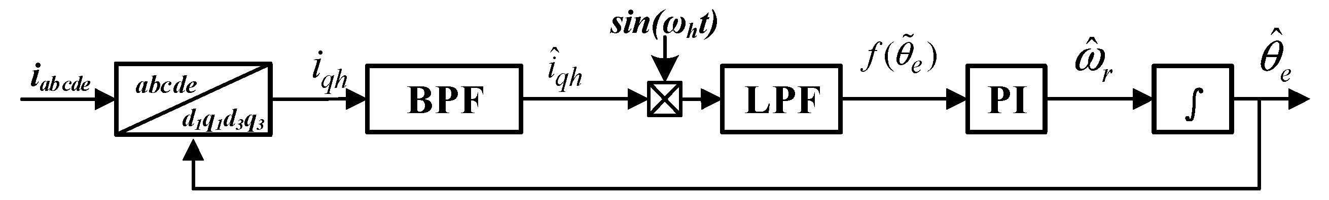
2.2. Conventional HF Injection Method

Based on [39], after injecting an HF voltage signal into the d-axis, the d ^ -axis and q ^ -axis HF current response expression, containing rotor position information, is expressed as
i ^ d h i ^ q h = U h sin ( ω h t ) ω h L 2 Δ L 2 L Δ L cos ( 2 θ ˜ e ) U h sin ( ω h t ) ω h L 2 Δ L 2 ( Δ L sin ( 2 θ ˜ e ) )
where Uh and ωh are the amplitude and frequency of the injected HF voltage signal, respectively; L = (Ld + Lq)/2 is the common mode inductance; and ΔL = (LdLq)/2 is the differential inductance.
According to (4), by demodulating the q-axis HF current, the corresponding rotor position estimation error information f ( θ ˜ e ) can be obtained as
f ( θ ˜ e ) = L P F ( i ^ q h sin ω h t ) = L U h 2 ω h L 2 Δ L 2 sin ( 2 θ ˜ e )
According to (5), the rotor position can be obtained through decoupling process. The block diagram of the pulse HF injection method is illustrated in Figure 2.

3. Analysis of Fault-Tolerant Sensorless Control

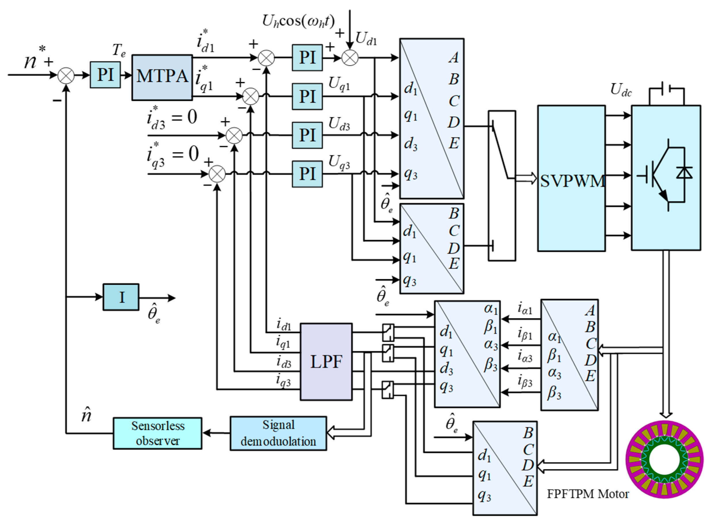
3.1. Universal Fault-Tolerant Control

The FPFTPM motor is physically the same in the open-circuit fault state and the normal state. In addition, due to its constant instantaneous permanent magnetic flux and extremely low harmonic content, the five-phase back EMF can be simplified as
e A e B e C e D e E = ω ψ f sin θ sin ( θ α ) sin ( θ 2 α ) sin ( θ 3 α ) sin ( θ 4 α )
where α is the spatial angle between the adjacent phase winding axes, α = 2π/5. According to the voltage equation of the five-phase motor, the voltage without considering the back EMF is
u A e u B e u C e u D e u E e = u A e A u B e B u C e C u D e D u E e E = R s i A i B i C i D i E + L s d d t i A i B i C i D i E
It can be seen from (7) that the new voltage equation contains only the current term. When the phase-A open-circuit fault occurs, iA = 0. The equal amplitude fault-tolerant control strategy is adopted to ensure that the fault-tolerance currents i B 1 , i C 1 , i D 1 , and i E 1 are symmetrical and equal in amplitude with ia as the boundary. Therefore, the fault-tolerant current for the phase-A open-circuit fault can be expressed as follows:
i B i C i D i E = sin ( θ 0.5 α ) cos ( θ 0.5 α ) sin ( 3 θ + α ) cos ( 3 θ + α ) sin ( θ 2 α ) cos ( θ 2 α ) sin ( 3 θ + 4 α ) cos ( 3 θ + 4 α ) sin ( θ + 2 α ) cos ( θ + 2 α ) sin ( 3 θ 4 α ) cos ( 3 θ 4 α ) sin ( θ + 0.5 α ) cos ( θ + 0.5 α ) sin ( 3 θ α ) cos ( 3 θ α ) i d 1 i q 1 i d 3 i q 3 = T p i d 1 i q 1 i d 3 i q 3
According to (8), the voltage without considering the back EMF under the condition of phase-A open-circuit fault can be written as
u B e * u C e * u D e * u E e * = T p u e d 1 * u e q 1 * u e d 3 * u e q 3 *
where u e d 1 * = u d 1 * e d 1 * , u e q 1 * = u q 1 * e q 1 * , u e d 3 * = u d 3 * e d 3 * , and u e q 3 * = u q 3 * e q 3 * . Substituting (9) into (7), the reference voltage of phase-A open-circuit fault can be expressed as
u B * u C * u D * u E * = T p u e d 1 * u e q 1 * u e d 3 * u e q 3 * + e B e C e D e E = 1.382 ( i q 1 cos ( θ 0.5 α ) + i d 1 sin ( θ 0.5 α ) + i q 3 cos ( 3 θ + α ) + i d 3 sin ( 3 θ + α ) ) + e B 1.382 ( i q 1 cos ( θ 2 α ) + i d 1 sin ( θ 2 α ) + i q 3 cos ( 3 θ + 4 α ) + i d 3 sin ( 3 θ + 4 α ) ) + e C 1.382 ( i q 1 cos ( θ + 2 α ) + i d 1 sin ( θ + 2 α ) + i q 3 cos ( 3 θ 4 α ) + i d 3 sin ( 3 θ 4 α ) ) + e D 1.382 ( i q 1 cos ( θ + 0.5 α ) + i d 1 sin ( θ + 0.5 α ) + i q 3 cos ( 3 θ α ) + i d 3 sin ( 3 θ α ) ) + e E
Thus, the traditional fault-tolerant sensorless control block diagram of the FPFTPM motor under a single-phase open-circuit fault can be obtained as shown in Figure 3.

3.2. Problems’ Description

From the above analysis of the conventional fault-tolerant and sensorless algorithm for the FPFTPM motor, it can be noticed that there are some problems, which are concluded as the following:
  • Traditional signum-function-based SMOs necessitate the use of LPFs for chattering reduction and delay compensation to mitigate LPF-induced phase delays, complicating the SMO architecture and degrading dynamic estimation accuracy in FPFTPM motor systems.
  • During the fault operation, the FPFTPM motor system will be operated in an asymmetric state. Meanwhile, the normal phase currents are severely distorted. Then, according to the above introduction of the fault-tolerant control method, it can be seen that when the FPFTPM motor has a single-phase open-circuit fault, the fault-tolerant control can be realized in the dq axis coordinate system by the reduced-order transformation. However, the use of the reduced-order transformation matrix makes the control system different between normal operation and fault operation, which will greatly increase the complexity of the sensorless drive control system, and the estimated performance under fault conditions will be degraded.
  • The problem 1 will further aggravate the problem 2.
Consequently, it is valuable to develop a novel sensorless fault-tolerant control method to overcome the above problems. Then, the redundant reduced-order coordinate transformation is dismissed completely, and the estimated performance of the full-speed sensorless under different operating conditions, including fault state, static, and dynamic state, can be greatly improved.

4. Fault-Tolerant Sensorless Control Based on HARO Scheme

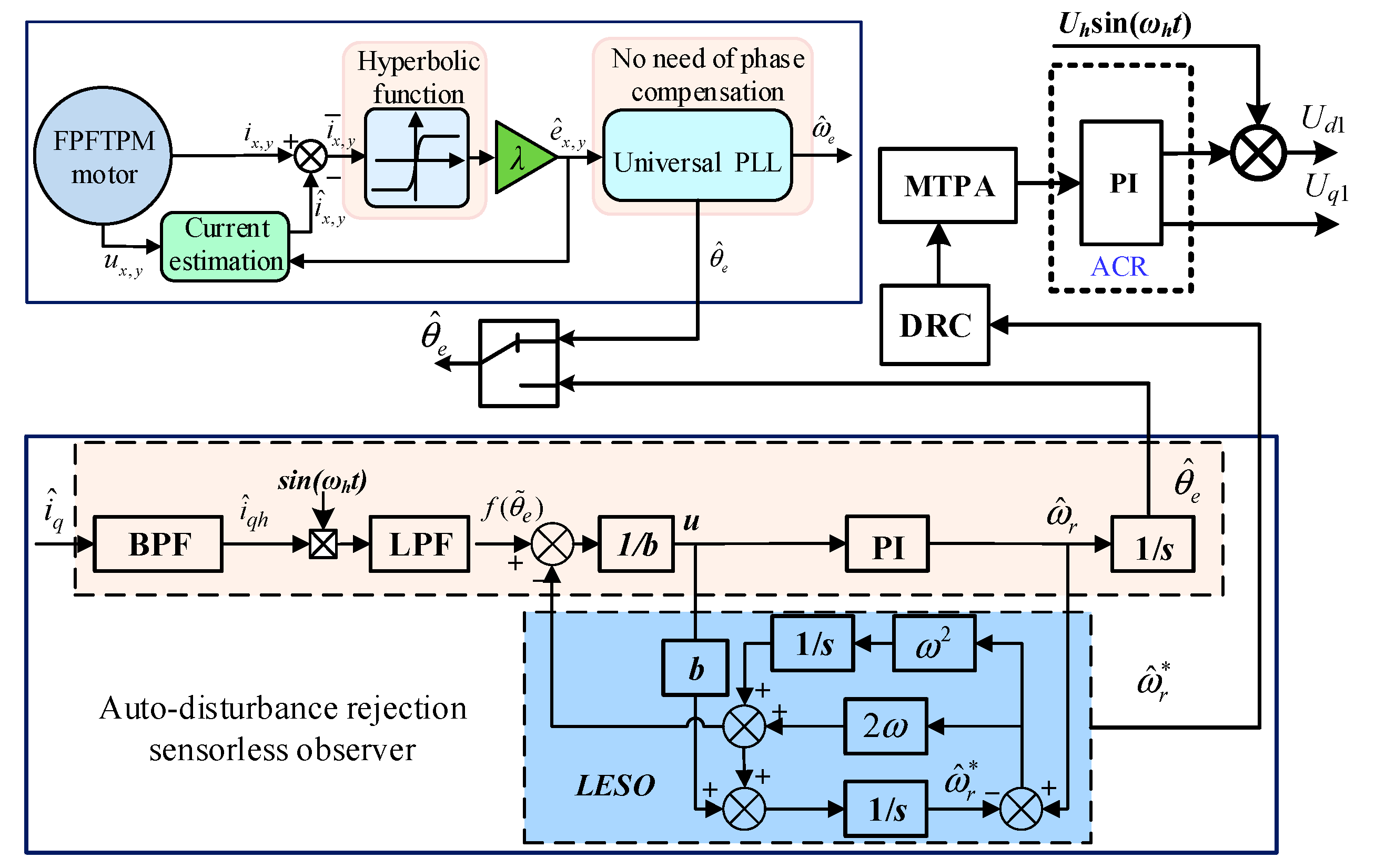
4.1. Steady-Healthy SMO for Medium/High-Speed Operation

For the FPFTPM motor system, the corresponding current equation of any two phases can be taken as
d i x d t = R s L s i x + 1 L s u x 1 L s e x d i y d t = R s L s i y + 1 L s u y 1 L s e y
where x,y∈1, 2, …, 5; ux and uy represent the x-th and y-th phase voltage; ix and iy represent the x-th and y-th phase current; and ex and ey represent the x-th and y-th phase back-EMF, which are expressed as
e x = E m sin ( θ e + 2 π 5 ( x 1 ) ) e y = E m sin ( θ e + 2 π 5 ( y 1 ) )
with
E m = ω e γ e
where γe and θe are the phase back-EMF coefficient and the rotor position with electric degree, respectively. Based on (11), the steady-healthy observer is proposed as
d i x d t = R s L s i ^ x + 1 L s u x λ L s H ( i ¯ x ) d i y d t = R s L s i ^ y + 1 L s u y λ L s H ( i ¯ y )
with
H ( i ¯ x ) = e a i ¯ x e a i ¯ x e a i ¯ x + e a i ¯ x H ( i ¯ y ) = e a i ¯ y e a i ¯ y e a i ¯ y + e a i ¯ y
where a is the adjustable parameter, which is a positive constant. In the observer, the boundary layer is defined as the magnitude of the independent variable when H = 0.99. With different values of a, the boundary layer can be regulated, as shown in Figure 4. By subtracting (11) from (14), the improved SMO model used for e ^ x and e ^ y estimation can be eventually established.
Based on [47], it can be known that effective chattering reduction in SMO systems requires switching functions to satisfy four criteria: (1) continuity, (2) saturation limits at ±1, (3) nonlinear slope within boundary layers, and (4) time-delay-free characteristics. From Figure 4, it can be found that the switching function adopted in this paper can meet the prerequisites mentioned previously. Thus, it can be concluded that it is not necessary to use LPF and phase compensation in the proposed observer, which can simplify the algorithm and improve the estimated performance.
Since the hyperbolic function is applied in the SMO with any two healthy phase back-EMFs, it is vital and essential to revalidate the stability of the observer.
Consider the Lyapunov function candidate as
V ( i ¯ ) = 1 2 i ¯ x 2 + 1 2 i ¯ y 2
V ˙ = i ¯ x i ¯ ˙ x + i ¯ y i ¯ ˙ y
Substitute (11) and (14) into (17), this can be derived as
V ˙ = R s L s i ¯ x 2 + E m i ¯ x L s sin ( θ e + 2 π 5 ( x 1 ) ) i ¯ x L s λ H ( i ¯ x ) R s L s i ¯ y 2 + E m i ¯ y L s sin ( θ e + 2 π 5 ( y 1 ) ) i ¯ y L s λ H ( i ¯ y ) £ R s L s ( i ¯ x 2 + i ¯ y 2 ) + E m L s ( i ¯ x + i ¯ y ) i ¯ x L s λ H ( i ¯ x ) i ¯ y L s λ H ( i ¯ y ) = R s L s ( i ¯ x 2 + i ¯ y 2 ) + i ¯ x L s ( E m λ H ( i ¯ x ) ) + i ¯ y L s ( E m λ H ( i ¯ y ) )
Choosing the design parameter λ as
λ > m a x ( E m H ( i ¯ x ) , E m H ( i ¯ y ) )
Then, we have
V ˙ = R s L s ( i x ¯ 2 + i y ¯ 2 ) < 0
Hence, according to the Lyapunov stability decision theorem, the proposed SMO can reach a stable state when the observer gain can meet the criteria in (19). It should be noted that different from the stability condition (2) in conventional SMO, λ should be chosen much larger because |H| is less than 1 over the boundary layer range.
In the conventional SMO, the estimated back-EMFs in the two-phase static frame are orthogonal. Also, the LPF is used to decrease the HF noise in the back-EMF estimation, which will cause a phase delay. Hence, a PLL with phase delay compensation is usually used to obtain the rotor position information. From the previous analysis of the phase back-EMF estimation method for the FPFTPM motor, it can be known that the obtained two-phase back-EMFs may not be orthogonal. Therefore, in this paper, a universal PLL without phase compensation is presented in Figure 5. Similarly to the orthogonal PLL, the universal PLL consists of the phase detector, the loop filter, and the voltage-controlled oscillator.
According to [44] and (11), e ^ x and e ^ y should be satisfied as follows
0 < 2 π 5 ( y x ) < π
Then, the following can be obtained:
sin 2 π 5 ( y x ) > 0
From Figure 5, the phase error in the phase detector can be taken as
Δ e = E ^ x sin ( θ ^ e + 2 π 5 ( y 1 ) ) E ^ y sin ( θ ^ e + 2 π 5 ( x 1 ) ) = E m sin ( θ e + 2 π 5 ( x 1 ) ) sin ( θ ^ e + 2 π 5 ( x 1 ) + 2 π 5 ( y x ) ) E m sin ( θ ^ e + 2 π 5 ( x 1 ) ) sin ( θ e + 2 π 5 ( x 1 ) + 2 π 5 ( y x ) ) = E m sin ( θ e + 2 π 5 ( x 1 ) ) cos ( θ ^ e + 2 π 5 ( x 1 ) ) sin 2 π 5 ( y x ) E m sin ( θ ^ e + 2 π 5 ( x 1 ) ) cos ( θ e + 2 π 5 ( x 1 ) ) sin 2 π 5 ( y x ) = E m sin 2 π 5 ( y x ) sin ( θ e θ ^ e )
From (22) and (23), it can be obtained that the phase detector output Δe is the estimated position error. Then, the estimated speed can be gained by the loop filter, while the estimated rotor position can be achieved via the loop filter and the voltage-controlled oscillator.

4.2. DAC Architecture for Zero/Low-Speed Operation

The relationship between the FPFTPM motor torque and the mechanical angular velocity can be expressed as
d ω r d t = B J ω r T L J + T e J
where ωr is the mechanical angular velocity, B denotes the damping coefficient, J represents the moment of inertia, and TL is the load torque.
For the FPFTPM motor under fault, the electromagnetic torque can be rewritten as follows:
T e = T d + Δ T e
where Td is the stable component of electromagnetic torque and ΔTe represents the torque ripple component of electromagnetic torque caused by fault disturbance. The design of Td is used to ensure the stability of the FPFTPM motor system and ΔTe is considered as an uncertain factor such as sudden failure of the motor system. According to [48], a disturbance robust controller (DRC) is adopted, and a disturbance control strategy is adopted to eliminate the torque ripple component ΔTe, thereby suppressing the torque ripple of the FPFTPM motor under variable working conditions.
Suppose ΔTe = ρ1Td, where ρ1 is unknown but bounded, ρ 1 ρ ^ 1 < 1 , ρ 1 is the absolute value of ρ1, and ρ ^ 1 is the upper bound of ρ1. Therefore, (24) can be rewritten as
d ω r d t = B h J h ω r + ( B h J h B J ) ω r T L J + 1 J h 1 ( 1 J h J ) ( T d + Δ T e ) = B h J h ω r + ( B h J h B J ) ω r T L J + 1 J h ( 1 ρ 2 ) ( 1 + ρ 1 ) T d
where Bh and Jh are the upper bounds of B and J, respectively, and are greater than 0. TL is load torque. ρ2 = 1 − (Jh/J) is the adjustable coefficient, 0 ≤ ρ2 < 1. Let δ = ωrωr*, ωr* be the mechanical angular velocity of the rotor. Then, (26) can be rewritten as follows:
d δ d t = B h J h δ + ( B h J h B J ) δ B J ω r * T L J + 1 J h ( 1 ρ 2 ) ( 1 + ρ 1 ) T d
According to the robust control law, the DRC is designed as follows:
T d = η χ η + ε
where χ = B h δ + B h ω r + T h ( 1 ρ ^ 1 ) ( 1 ρ ^ 2 ) , δ is the absolute value of δ, ω r is the absolute value of ωr, Th is the maximum value of TL and is greater than 0, ρ ^ 2 is the maximum value of ρ2, and η = δ J h χ , ε is a constant greater than 0.
In order to verify that (27) and (28) have uniform boundedness and uniform ultimate boundedness, Lyapunov stability theory is used for analysis. Equation (27) can be written as
δ ˙ = B h J h δ + ( B h J h B J ) δ B J ω r * T L J + 1 J h ( 1 ρ 2 ) ( 1 + ρ 1 ) T d
The Lyapunov function is defined as
V = 1 2 δ 2
Combining (29) and (30), V ˙ can be obtained as
V ˙ = δ δ ˙ = B h J h δ 2 + ( B h J h B J ) δ 2 B J ω r * δ T L J δ + δ J h ( 1 ρ 2 ) ( 1 + ρ 1 ) T d B h J h δ 2 + B h J h δ 2 + B J ω r * δ + T L J δ + δ J h ( 1 ρ 2 ) ( 1 + ρ 1 ) T d = B h J h δ 2 + δ J h B δ + B ω r * + T L + δ J h ( 1 ρ 2 ) ( 1 + ρ 1 ) T d
Substituting (28) into (31), V ˙ ( δ ) can be obtained as
V ˙ ( δ ) B h J h δ 2 + δ J h B δ + B ω r * + T L + δ J h ( 1 ρ 2 ) ( 1 + ρ 1 ) ( η χ η + ε ) B h J h δ 2 + ( 1 ρ ^ 2 ) ( 1 ρ ^ 1 ) η + ( 1 ρ ^ 1 ) ( 1 ρ ^ 2 ) η 2 + ε 2 η + ε = B h J h δ 2 + ( 1 ρ ^ 1 ) ( 1 ρ ^ 2 ) ε
From Analysis (32), it can be known that B h J h δ 2 0 , ( 1 ρ ^ 1 ) ( 1 ρ ^ 2 ) ε > 0 . Therefore, the solution of the system is uniformly ultimately bounded, which verifies the stability of the control system.
After DRC is adopted in the speed loop, the torque ripple caused by the fault is controlled. However, for zero-low-speed sensorless control, due to the current distortion and harmonic interference after the fault, it will also be disturbed by the fault during observation. This will affect the injection and extraction of HF signals, resulting in performance degradation. Therefore, it is necessary to observe and compensate the fault as a disturbance in the position observation.
Extended state observer (ESO) possesses the unique advantage of tolerating all the uncertainties excellently, and the total disturbance can be estimated and compensated timely and accurately. Therefore, ESO can be used to suppress the disturbance in the observer and an auto-disturbance rejection sensorless observer is designed, the ESO is established as
d d t x ^ 1 = x ^ 2 + b u d d t x ^ 2 = h 1 d d t ( y x ^ 1 ) + h 2 ( y x ^ 1 )
where x ^ 1 and x ^ 2 are the estimated speed and disturbance, y is the differential of the estimated position, and h1 and h2 are the observer gains.
The control law of the ESO is designed as
u = 1 b ( u 0 x ^ 2 )
where u0 = f ( θ ˜ e ) is the system input. Laplace transform is performed on (33), which can be obtained as
x ^ 1 = b s s 2 + h 1 s + h 2 u + h 1 s + h 2 s 2 + h 1 s + h 2 y x ^ 2 = b ( h 1 s + h 2 ) s 2 + h 1 s + h 2 + s ( h 1 + h 2 ) s 2 + h 1 s + h 2 y
The observer gains can be parameterized as
[ h 1 h 2 ] T = [ 2 ω ω 2 ] T
where ω is the bandwidth of the observer. The observer bandwidth ω governs a critical trade-off between noise suppression and dynamic performance. While a larger ω enhances transient tracking accuracy and disturbance rejection capability, it simultaneously amplifies HF noise sensitivity. To balance these competing objectives, ω is selected as 40 in this paper. This value ensures rapid convergence of estimated states while maintaining effective filtering of switching harmonics and measurement noise.
Based on the above analysis, the HARO sensorless control scheme can be obtained, as illustrated in Figure 6. In this paper, the pulsating HF signal injection method is used for zero/low-speed sensorless control. In the experimental platform, the switching frequency of the inverter is 10 kHz, and the HF signal injection frequency is selected as 500 Hz. Therefore, to achieve excellent control effect, a 10% rated speed is selected for algorithm switching between low-speed and high-speed range, and the traditional weighted average algorithm is used for algorithm switching in the transition region to realize the self-detection of rotor position in the full speed range of variable working conditions. For zero/low-speed sensorless control, the disturbance is suppressed and compensated in the speed loop and the position observation, respectively. At this time, the fault is also regarded as a disturbance. The torque ripple is suppressed, and the high performance sensorless control under fault and normal conditions is realized. For medium/high speed sensorless control, it can be found that any two normal phase back-EMFs and the hyperbolic function work together to construct the steady-healthy SMO. When the phase winding faults occur, the proposed steady-healthy SMO can directly extract any two normal phase back-EMF information without requiring the coordinate transformation. Compared with conventional methods, HARO balances computational complexity and disturbance rejection through a unified architecture. The proposed method introduces additional computational load, but does not require complex transformation, and the torque ripple and position estimation error are reduced in both healthy and fault states. Hence, the sensorless drive system of the FPFTPM motor can work well even in fault conditions.

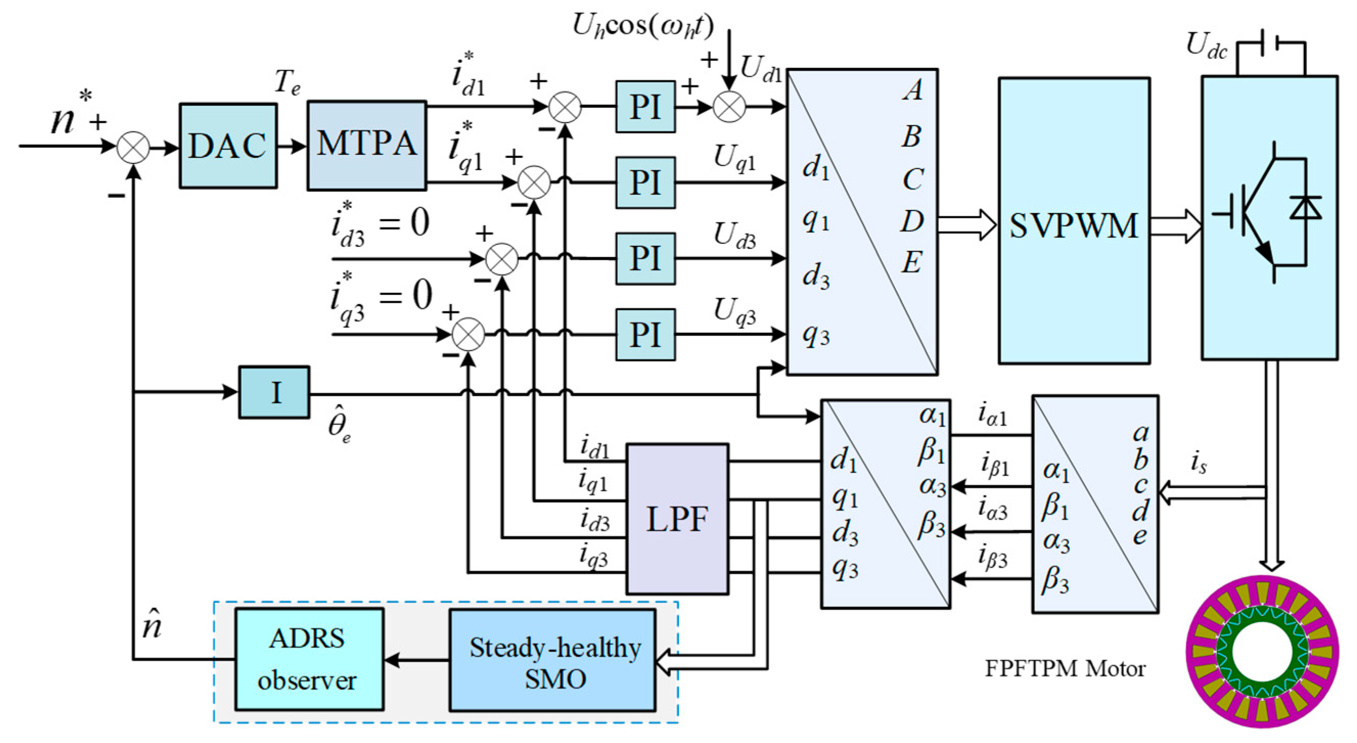
5. FPFTPM Motor Sensorless Control Drive System

To improve the reliability of the FPFTPM motor drive system, the sensorless control strategy under fault conditions, as shown in Figure 7, is proposed in this paper. When the fault occurs in the FPFTPM motor drive system, the FPFTPM motor system operates at an asymmetric state, and the remaining healthy phase currents are severely distorted. Therefore, it is difficult to directly apply the existing sensorless control methods under fault conditions. In the proposed sensorless control drive system, the DRC is employed to generate smooth torque by the remaining healthy phase winding. In addition, the proposed SMO and ESO control are used to realize sensorless control operation under fault conditions.
From the proposed fault-tolerant sensorless FPFTPM motor drive system, compared with Figure 3, a full-speed sensorless control with a simpler structure is realized. For medium/high speed sensorless control, it can be known that because any two healthy phase back-EMFs are utilized in the proposed SMO-based sensorless control strategy, as introduced in Section 4, it is not necessary to use any coordinate transformation. Then, the proposed SMO is capable of possessing good robustness to various uncertainties, which makes for good sensorless performance under fault conditions. Moreover, due to the use of the hyperbolic function, there is no need to use LPF and phase compensation in the proposed SMO, which can simplify the algorithm and improve the estimated static and dynamic performance. For zero/low speed sensorless control, a DAC architecture is designed. In the speed loop and the position loop, the fault is suppressed as a disturbance by robust control rate and ESO control, respectively. Without complex transformation, the torque ripple and position estimation error are reduced in both healthy and fault states. Therefore, it can be concluded that the proposed FPFTPM motor drive system has high reliability.

6. Verification Results

To validate the proposed sensorless control strategy for the FPFTPM motor, the system shown in Figure 7 was simulated using MATLAB R2021b/Simulink. Also, its experimental setup is built as presented in Figure 8, and the motor parameters are shown in Table 1. The voltage inverter employs FF100R12RT4 (Infineon, Neubiberg, Germany) insulated gate bipolar transistor (IGBT) modules operating at a 10 kHz switching frequency. The HARO algorithm and vector control strategy are implemented on a dSPACE DS1007 controller (dSPACE Mechatronic Control Technology, Paderborn, Germany). An incremental encoder measures the actual rotor position, while LA25NP Hall current sensors and LV25NP voltage sensors (LEM, Beijing, China) acquire phase currents and DC bus voltage, respectively. Phase voltages are calculated by the digital controller using DC bus voltage and inverter switching signals. In addition, the magnetic power brake is applied as the load to provide the required load torque, with torque values recorded through a torque sensor.

6.1. Steady-State Performance

The sensorless operating performance is influenced by the parameter of a in the hyperbolic function because it is closely associated with the boundary layer of the hyperbolic function and the chattering suppression. Figure 9 shows the simulation results of the estimated back-EMF under different a when the FPFTPM motor operates at 300 r/min. It can be observed that the harmonics accounts for 12.3%, 8.7%, 4.4%, and 1.6% for a = 0.2, 0.1, 0.05, and 0.01, respectively. Hence, with the increase in a, the chattering will be reduced because of the decrease in THD. However, the magnitude of the estimated back-EMF experiences a downward trend. It should be noticed that when a reaches a certain value, the magnitude of the estimated back-EMF and THD will remain little change. To simultaneously guarantee good steady-state and dynamic control performance, a is set as 0.01 in this paper. In addition, it is worth noting that Figure 9a,b give the B and C phase back-EMFs, while Figure 9c,d illustrate the A and C phase back-EMFs. So, any two healthy phase back-EMFs can be utilized to estimate the position, which can verify the feasibility of the proposed algorithm.
In order to verify the effectiveness of the proposed strategy, a higher speed DAC control and a lower speed SMO control are selected for control. Figure 10 compares the steady-state normal operating performance of the conventional and proposed steady-healthy SMO when the FPFTPM motor runs at 50 r/min. Compared to the estimated speed of the proposed SMO in Figure 10b and the conventional SMO in Figure 10a, it can be known that the estimated speed pulsation of the proposed SMO can be decreased greatly, and the speed error can be reduced by about 56%. Additionally, the rotor position error of the proposed SMO can be reduced by about 60%, which can be obtained from Figure 10c,d. Since the estimated errors of both algorithms are within ±0.2 rad, the FPFTPM motor under sensorless operation can be controlled to run well.
Figure 11 shows the experimental results of the normal operation based on traditional and the proposed DAC-based sensorless control. The speed of stable operation is 120 rpm and the load is 2N·m. It can be seen from Figure 11a that under normal operation, the peak-to-peak value of position estimation error is 0.175 rad, the peak-to-peak value of speed estimation error is 20.2 rpm, and the torque ripple is 0.642 N·m. It can be seen from Figure 11b that under normal operation, the peak-to-peak value of position estimation error is 0.102 rad, which is reduced by 41.7%; the peak-to-peak value of speed estimation error is 15.4 rpm, which is reduced by 23.8%; and the torque ripple is 0.325 N·m, which is reduced by 49.4%. It can be seen that the steady-state performance of the sensorless control with the proposed DAC is greatly improved.

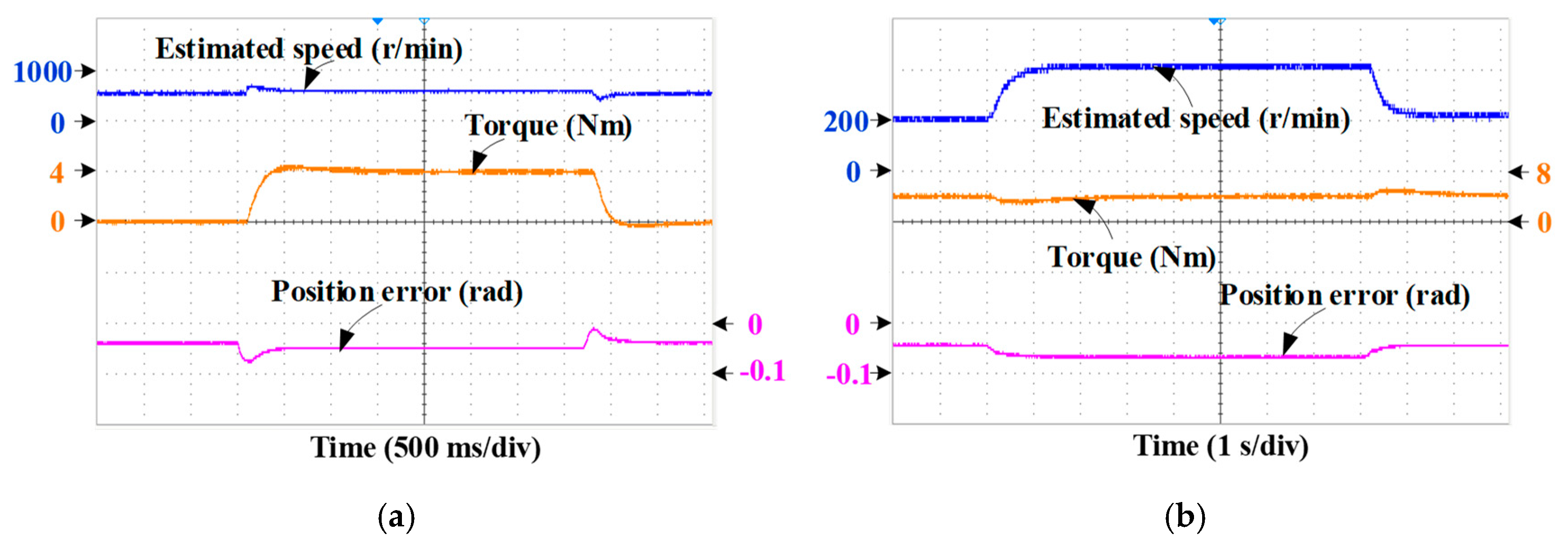
6.2. Dynamic-State Performance

Figure 12 shows the experimental results of variable speed and variable load of fault-tolerant sensorless control based on the proposed DAC during normal operation. It can be seen from Figure 12a that when the load is changed, the motor speed is 120 rpm, and the load is suddenly increased from 2 N·m to 5 N·m, and then suddenly reduced to 2 N·m. When the motor is loaded, the position estimation error does not overshoot, and it is stable at 0.15 rad after variable load. When the motor is reduced, the position estimation error is stable at 0.07 rad. It can be seen that the position estimation accuracy is high and the response time is short. It can be seen from Figure 12b that when the speed is changed, the speed is accelerated from 60 rpm to 120 rpm and then decelerated to 60 rpm, and the load is 2 N·m. When the motor is accelerated, the position estimation error is −0.27 rad, and when the motor is decelerated, the position estimation error is 0.38 rad. The estimation errors of rotor position and speed are small when the speed is changed; the FPFTPM motor under sensorless operation can be controlled to run well. It can be seen that the fault-tolerant position sensorless control of the proposed DAC has good dynamic performance when the motor is in normal operation.
In addition, Figure 13 shows the estimated back-EMFs of the conventional and proposed SMO at the speed of 400 r/min. Note that the optimal parameters are chosen in the conventional SMO in Figure 13a and the proposed SMO in Figure 13c. It can be observed that the chattering of the proposed strategy is greatly improved since the total harmonic distortion (THD) of 1.85% and 5.8% for the estimated back-EMFs of the proposed and conventional SMO. Furthermore, Figure 13b,c compare the estimated back-EMF under different a. It can be known that a has a great impact on the sensorless operating performance. Also, the back-EMFs in Figure 13b,c are estimated with different two-phase currents and voltages. Therefore, it can be concluded that any two healthy phase back-EMFs can be applied to estimate the rotor position.
The dynamic performance of the proposed steady-healthy SMO is tested, as shown in Figure 14. When a sudden load of 4 N·m is imposed on the shaft, the estimated speed changes a little, but quickly recovers to the commanded speed of 600 r/min. Similarly, when the load is unloaded, the estimated speed can fast return to the given value. Although the rotor position error increases at the moment of loading and unloading, it can keep a small value, which is within ±0.1 rad. Also, the rotor position error does not increase as the load increases. Then, the impact of the load change on the position estimation accuracy can be nearly ignored. When the reference speed changes from 200 to 400 r/min, the estimated speed can effectively track the actual speed because of the small rotor position error at the entire changed speed operating range. Therefore, the above analysis demonstrates that the proposed SMO possesses good dynamic-state performance.
To verify the robustness of the proposed SMO to the changed motor parameters, the estimated performance when the motor parameters vary with 300 r/min under healthy condition are given. Figure 15a illustrates the sensorless control performance with phase resistance change by 60% of its original value (from 0.5 Ω to 0.8 Ω), while Figure 15b shows the sensorless control performance with phase inductance change by 22.2% of its original value (from 13.5 mH to 16.5 mH). The changed value of phase resistance and inductance are used in this paper only for demonstration purposes. It can be observed that for the proposed SMO, although the phase resistance or the phase inductance changes, there is almost no estimated error variation for the rotor position. Therefore, the proposed SMO also has strong robustness to the changed motor parameters.
Table 2 shows the sensorless control performance comparison of the conventional strategy and the HARO strategy under different operating. It can be concluded that under the proposed HARO strategy, the torque ripple, speed, and position errors have all been effectively reduced, and it has strong robustness to the change in motor parameters.

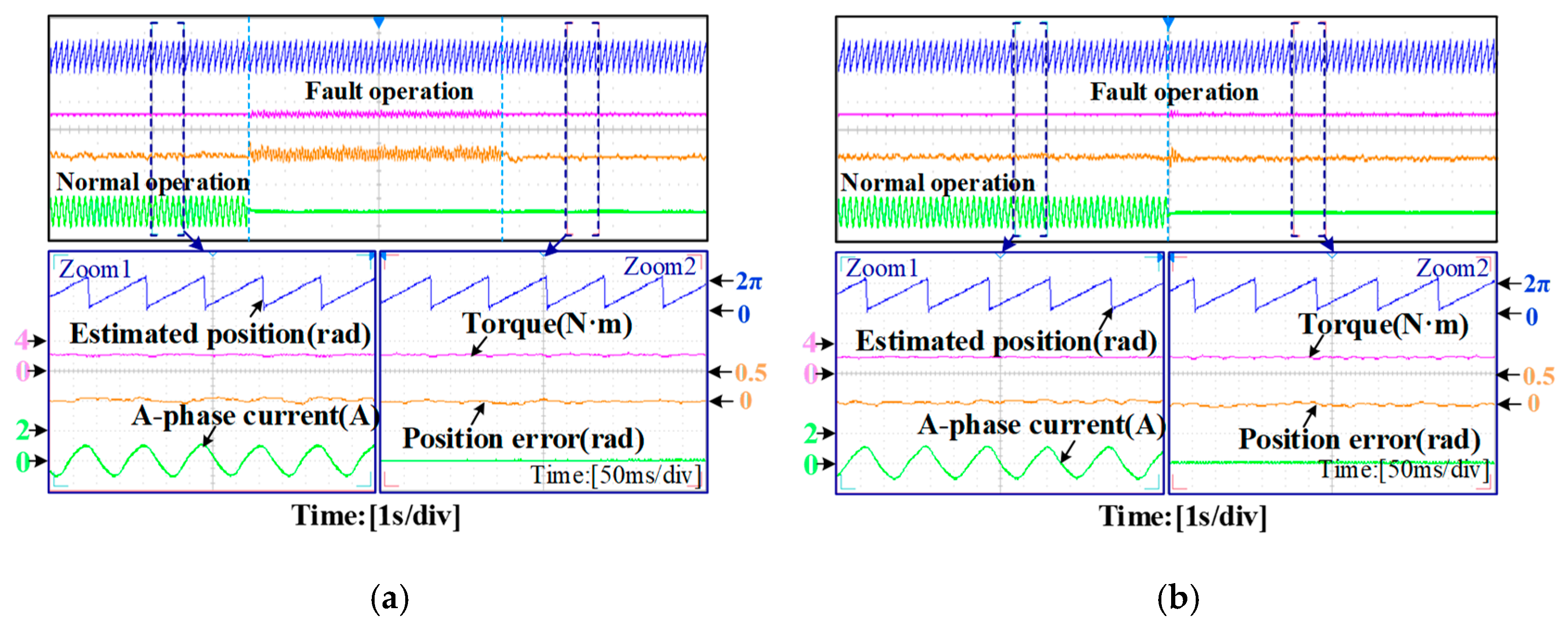
6.3. Fault Operating Performance

Figure 16 shows the sensorless control performance of the proposed SMO under one-phase open-circuit fault conditions at 500 r/min. When phase-A winding open-circuit fault occurs, its current drops to zero. With the fault-tolerant control strategy, the non-ripple torque output in post-fault operation can be ensured. In addition, the estimated rotor position can stay around their actual values even in the fault transient process, which shows the good steady-healthy performance of the proposed sensorless control. Hence, the proposed SMO has good fault operating performance.
Figure 17 shows the experimental results of the FPFTPM motor in normal, faulty, and fault-tolerant operation. Figure 17a is the fault-tolerant sensorless control method using the traditional fault-tolerant algorithm and Figure 17b is the fault-tolerant sensorless control method of the proposed DAC. It can be seen that under the two control methods, the torque ripple during the fault-tolerant operation of the motor is suppressed, and the fault-tolerant sensorless operation can be realized. In addition, the torque ripple of the sensorless control system based on the traditional fault-tolerant algorithm increases significantly when the motor fails, which is about four times that of the normal operation. The torque ripple can only be suppressed when the fault-tolerant algorithm is switched. In contrast, the proposed method can enter the fault-tolerant mode to suppress the torque ripple when the motor fault occurs, which can avoid the redundant reduction-order transformation of the traditional fault-tolerant algorithm and simplify the fault-tolerant position sensorless control system.

7. Conclusions

To meet the requirements of high performance and high reliability of the driving system for agricultural equipment applications, in this paper, a sensorless control strategy of the FPFTPM motor under fault conditions has been proposed. At zero/low speeds, the fault is regarded as a disturbance and suppressed in the speed loop and the position loop, respectively. Without fault detection and coordinate transformation, the system structure is simplified, and the HF signal can be injected normally under fault. At medium/high speeds, due to the proposed combination of any two healthy phase back-EMFs and a hyperbolic function to construct the steady-healthy SMO, any coordinate transformation, the LPF, and the extra compensator are not required any longer. In addition, the universal PLL without phase compensation has been presented to obtain the rotor position information, which can simplify the SMO structure. Furthermore, the sensorless control algorithm with delay suppression for the FPFTPM motor system provides the merits of restrained system chattering and good estimated accuracy under different operating conditions.
Based on a prototype of the FPFTPM motor, the evaluation of performances for the driving system has been implemented by experiment. The results have verified the feasibility and validity of this sensorless control driving system for the FPFTPM motor. Quantitative verification confirms the robustness of the strategy. Under steady-state conditions, the position error is reduced to 0.04 rad, the speed error is reduced to 4 rpm, and the full-speed operation is maintained without algorithm reconstruction. Since the proposed control strategy can achieve undisturbed sensorless control operation under fault conditions, the reliability of the FPFTPM motor system can be adequately improved, which is suitable for agricultural equipment applications. Nevertheless, winding faults primarily degrade torque performance through increased ripple and reduced average torque. Although the proposed algorithm effectively suppresses ripple via robust disturbance rejection, its inherent inability to compensate for average torque loss may limit extreme-load applications, necessitating future compensation strategies. In addition, the proposed strategy can also be extended to conventional three-phase motors.

Author Contributions

Conceptualization, Z.P.; methodology, Z.P. and L.Z.; software, Z.P.; validation, L.Z., Z.P., H.F. and Y.W.; formal analysis, Z.P.; investigation, Y.W. and H.F.; resources, L.Z.; data curation, Y.W. and H.F.; writing—original draft preparation, Z.P. and L.Z.; writing—review and editing, Y.W. and H.F.; project administration, L.Z.; funding acquisition, L.Z. All authors have read and agreed to the published version of the manuscript.

Funding

This research was supported in part by the National Natural Science Foundation of China under Grant 52277051.

Data Availability Statement

The original contributions presented in this study are included in the article. Further inquiries can be directed to the corresponding author.

Conflicts of Interest

Author Yucheng Wang was employed by the State Grid Zhenjiang Power Supply Company. The remaining authors declare that the research was conducted in the absence of any commercial or financial relationships that could be construed as a potential conflict of interest.

References

  1. Zhu, Z.; Chai, X.; Xu, L.; Quan, L.; Yuan, C.; Tian, S. Design and performance of a distributed electric drive system for a series hybrid electric combine harvester. Biosyst. Eng. 2023, 236, 160–174. [Google Scholar] [CrossRef]
  2. Li, H.; Chen, L.; Zhang, Z. A Study on the Utilization Rate and Influencing Factors of Small Agricultural Machinery: Evidence from 10 Hilly and Mountainous Provinces in China. Agriculture 2023, 13, 51. [Google Scholar] [CrossRef]
  3. Han, J.; Wang, F. Design and Testing of a small orchard tractor driven by a power battery. Eng. Agric. 2023, 43, e20220195. [Google Scholar]
  4. Yuan, J.; Ji, W.; Feng, Q. Robots and Autonomous Machines for Sustainable Agriculture Production. Agriculture 2023, 13, 1340. [Google Scholar] [CrossRef]
  5. Hu, J.; Zhao, X.; Liu, W.; Yao, M.; Zhao, J. Development of a Seeding Control Method Based on Seed Height in the Hopper of a Precision Wheat Drill. Appl. Eng. Agric. 2021, 37, 1131–1138. [Google Scholar] [CrossRef]
  6. Zhu, Q.; Zhu, Z.; Zhang, H.; Gao, Y.; Chen, L. Design of an Electronically Controlled Fertilization System for an Air-Assisted Side-Deep Fertilization Machine. Agriculture 2023, 13, 2210. [Google Scholar] [CrossRef]
  7. Li, J.; Shang, Z.; Li, R.; Cui, B. Adaptive Sliding Mode Path Tracking Control of Unmanned Rice Transplanter. Agriculture 2022, 12, 1225. [Google Scholar] [CrossRef]
  8. Lu, E.; Xue, J.; Chen, T.; Jiang, S. Robust Trajectory Tracking Control of an Autonomous Tractor-Trailer Considering Model Parameter Uncertainties and Disturbances. Agriculture 2023, 13, 869. [Google Scholar] [CrossRef]
  9. Cui, B.; Cui, X.; Wei, X.; Zhu, Y.; Ma, Z.; Zhao, Y.; Liu, Y. Design and Testing of a Tractor Automatic Navigation System Based on Dynamic Path Search and a Fuzzy Stanley Model. Agriculture 2024, 14, 2136. [Google Scholar] [CrossRef]
  10. Shi, J.; Hu, J.; Li, J.; Liu, W.; Yue, R.; Zhang, T.; Yao, M. Design and Experiment of Planting Mechanism of Automatic Transplanter for Densely Planted Vegetables. Agriculture 2024, 14, 1357. [Google Scholar] [CrossRef]
  11. Shi, Q.; Liu, D.; Mao, H.; Shen, B.; Li, M. Wind-induced response of rice under the action of the downwash flow field of a multi-rotor UAV. Biosyst. Eng. 2021, 203, 60–69. [Google Scholar] [CrossRef]
  12. Shi, Y.; Lorenz, R.D.; Valenzuela, A.M. New developments in loss minimizing control for drives without compromising torque dynamics. IEEE Trans. Ind. Appl. 2016, 6, 5327–5335. [Google Scholar] [CrossRef]
  13. Li, X.L.; Wang, X.Y.; Yu, S.Y. Design and analysis of a novel transverse-flux tubular linear switched reluctance machine for minimizing force ripple. IEEE Trans. Ind. Electron. 2020, 7, 741–753. [Google Scholar] [CrossRef]
  14. Yang, S.; Zhai, C.; Gao, Y.; Dou, H.; Zhao, X.; He, Y.; Wang, X. Planting Uniformity Performance of Motor-Driven Maize Precision Seeding Systems. Int. J. Agric. Biol. Eng. 2022, 15, 101–108. [Google Scholar] [CrossRef]
  15. Yu, Y.; Hao, S.; Guo, S.; Tang, Z.; Chen, S. Motor Torque Distribution Strategy for Different Tillage Modes of Agricultural Electric Tractors. Agriculture 2022, 12, 1373. [Google Scholar] [CrossRef]
  16. Liu, J.; Xia, C.; Jiang, D.; Sun, Y. Development and testing of the power transmission system of a crawler electric tractor for greenhouses. Appl. Eng. Agric. 2020, 36, 797–805. [Google Scholar] [CrossRef]
  17. Liu, H.; Yan, S.; Shen, Y.; Li, C.; Zhang, Y.; Hussain, F. Model predictive control system based on direct yaw moment control for 4WID self-steering agriculture vehicle. Int. J. Agric. Biol. Eng. 2021, 14, 175–181. [Google Scholar] [CrossRef]
  18. Li, J.; Wu, Z.; Li, M.; Shang, Z. Dynamic Measurement Method for Steering Wheel Angle of Autonomous Agricultural Vehicles. Agriculture 2024, 14, 1602. [Google Scholar] [CrossRef]
  19. Sun, J.; Wang, Z.; Ding, S.; Xia, J.; Xing, G. Adaptive disturbance observer-based fixed time nonsingular terminal sliding mode control for path-tracking of unmanned agricultural tractors. Biosyst. Eng. 2024, 246, 96–109. [Google Scholar] [CrossRef]
  20. Lu, E.; Ma, Z.; Li, Y.M.; Xu, L.Z.; Tang, Z. Adaptive backstepping control of tracked robot running trajectory based on real-time slip parameter estimation. Int. J. Agric. Biol. Eng. 2020, 13, 178–187. [Google Scholar] [CrossRef]
  21. Zhu, Z.; Yang, Y.; Wang, D.; Cai, Y.; Lai, L. Energy Saving Performance of Agricultural Tractor Equipped with Mechanic-Electronic-Hydraulic Powertrain System. Agriculture 2022, 12, 436. [Google Scholar] [CrossRef]
  22. Zhang, B.; Bai, T.; Wu, G.; Wang, H.; Zhu, Q.; Zhang, G.; Meng, Z.; Wen, C. Fatigue Analysis of Shovel Body Based on Tractor Subsoiling Operation Measured Data. Agriculture 2024, 14, 1604. [Google Scholar] [CrossRef]
  23. Zhu, Y.; Cui, B.; Yu, Z.; Gao, Y.; Wei, X. Tillage Depth Detection and Control Based on Attitude Estimation and Online Calibration of Model Parameters. Agriculture 2024, 14, 2130. [Google Scholar] [CrossRef]
  24. Ahmed, S.; Qiu, B.; Ahmad, F.; Kong, C.W.; Xin, H. A state-of-the-art analysis of obstacle avoidance methods from the perspective of an agricultural sprayer UAV’s operation scenario. Agronomy 2021, 11, 1069. [Google Scholar] [CrossRef]
  25. Zhang, L.; Li, X.Q.; Zhu, X.Y.; Zhang, C.H. Design and Optimization of a Five-Phase Reverse-Salient Fault-Tolerant Permanent Magnet Motor for Electric Vehicles. IEEE. Trans. Ind. Electron 2024. early access. [Google Scholar] [CrossRef]
  26. Wu, H.; Zhang, J.; Ding, S.; Huang, Y.; Hua, W. Cost function-based open-phase fault diagnosis for PMSM drive system with model predictive current control. IEEE Trans. Power Electron. 2021, 36, 2574–2583. [Google Scholar] [CrossRef]
  27. Zhang, L.; Fan, Y.; Lorenz, R.D.; Nied, A.; Cheng, M. Design and comparison of three-phase and five-phase FTFSCW-IPM motor open-end winding drive systems for electric vehicles applications. IEEE Trans. Veh. Technol. 2018, 67, 385–396. [Google Scholar] [CrossRef]
  28. Zhang, L.; Fan, Y.; Cui, R.H.; Lorenz, R.D.; Cheng, M. Fault-tolerant direct torque control of five-phase FTFSCW-IPM motor based on analogous three-phase SVPWM for electric vehicle applications. IEEE Trans. Veh. Technol. 2018, 67, 910–919. [Google Scholar] [CrossRef]
  29. Tang, L.; Wang, W.; Zhang, C.; Wang, Z.; Ge, Z.; Yuan, S. Linear Active Disturbance Rejection Control System for the Travel Speed of an Electric Reel Sprinkling Irrigation Machine. Agriculture 2024, 14, 1544. [Google Scholar] [CrossRef]
  30. Gao, Y.; Feng, K.; Yang, S.; Han, X.; Wei, X.; Zhu, Q.; Chen, L. Design and Experiment of an Unmanned Variable-Rate Fertilization Control System with Self-Calibration of Fertilizer Discharging Shaft Speed. Agronomy 2024, 14, 2336. [Google Scholar] [CrossRef]
  31. He, Y.; Zhu, Q.; Fu, W.; Luo, C.; Cong, Y.; Qin, W.; Meng, Z.; Chen, L.; Zhao, C.; Wu, G.J. Design and experiment of a control system for sweet potato seedling-feeding and planting device based on a pre-treatment seedling belt. J. Agric. Eng. 2022, 53, 187–196. [Google Scholar]
  32. Dai, D.; Chen, D.; Wang, S.; Li, S.; Mao, X.; Zhang, B.; Wang, Z.; Ma, Z. Compilation and Extrapolation of Load Spectrum of Tractor Ground Vibration Load Based on CEEMDAN-POT Model. Agriculture 2023, 13, 125. [Google Scholar] [CrossRef]
  33. Chen, Y.; Chen, L.; Wang, R.; Xu, X.; Shen, Y.; Liu, Y. Modeling and test on height adjustment system of electrically-controlled air suspension for agricultural vehicles. Int. J. Agric. Biol. Eng. 2016, 9, 40–47. [Google Scholar]
  34. Li, Y.; Xu, L.; Lv, L.; Shi, Y.; Yu, X. Study on Modeling Method of a Multi-Parameter Control System for Threshing and Cleaning Devices in the Grain Combine Harvester. Agriculture 2022, 12, 1483. [Google Scholar] [CrossRef]
  35. Gao, Y.; Yang, Y.; Fu, S.; Feng, K.; Han, X.; Hu, Y.; Zhu, Q.; Wei, X. Analysis of Vibration Characteristics of Tractor–Rotary Cultivator Combination Based on Time Domain and Frequency Domain. Agriculture 2024, 14, 1139. [Google Scholar] [CrossRef]
  36. Ding, Z.; Tang, Z.; Zhang, B.; Ding, Z. Vibration Response of Metal Plate and Shell Structure under Multi-Source Excitation with Welding and Bolt Connection. Agriculture 2024, 14, 816. [Google Scholar] [CrossRef]
  37. Xu, Y.; Wang, Y.; Iida, R.; Lorenz, R.D. Extending low-speed self-sensing via flux tracking with volt-second sensing. IEEE Trans. Ind. Appl. 2018, 54, 4405–4414. [Google Scholar] [CrossRef]
  38. Zhang, L.; Zhang, M.; Zhu, X.Y.; Pei, Z.F.; Chen, X. Space Decoupling Sensorless Control of Five-Phase Flux-Intensifying PM Motor Based on AFCCF-SMO Considering Flux-Weakening Operation. IEEE Trans. Ind. Electron. 2024. early access. [Google Scholar] [CrossRef]
  39. Xu, S.; Wang, D.; Wang, B.; Wang, X.; Miao, W.; Wang, X. Sideband electromagnetic vibrations in interior PMSM with high frequency pulsating injection sensorless control. IEEE Trans. Energy Convers. 2024, 39, 1919–1929. [Google Scholar] [CrossRef]
  40. Zhu, Z.; Zeng, L.; Chen, L.; Zou, R.; Cai, Y. Fuzzy Adaptive Energy Management Strategy for a Hybrid Agricultural Tractor Equipped with HMCVT. Agriculture 2022, 12, 1986. [Google Scholar] [CrossRef]
  41. Yue, R.; Yao, M.; Zhang, T.; Shi, J.; Zhou, J.; Hu, J. Design and Experiment of Dual-Row Seedling Pick-Up Device for High-Speed Automatic Transplanting Machine. Agriculture 2024, 14, 942. [Google Scholar] [CrossRef]
  42. Green, S.; Atkinson, D.J.; Jack, A.G.; Mecrow, B.C.; King, A. Sensorless operation of a fault tolerant PM drive. IEE Proc.—Electr. Power Appl. 2003, 150, 117–125. [Google Scholar] [CrossRef]
  43. Zhang, L.; Fan, Y.; Li, C.X.; Nied, A.; Cheng, M. Fault-tolerant sensorless control of five-phase FTFSCW-IPM motor based on a wide-speed strong-robustness sliding mode observer. IEEE Trans. Energy Convers. 2018, 33, 87–95. [Google Scholar] [CrossRef]
  44. Xu, J.; Du, Y.; Zhang, B.; Fang, H.; Guo, H.; Chen, Y. Sensorless fault tolerant control with phase delay compensation for aerospace FTPMSM drives with phase open-circuit and short-circuit faults. IEEE Trans. Ind. Electron. 2020, 68, 4576–4585. [Google Scholar] [CrossRef]
  45. Gaeta, A.; Scelba, G.; Consoli, A. Sensorless vector control of pm synchronous motors during single-phase open-circuit faulted conditions. IEEE Trans. Ind. Appl. 2013, 48, 1968–1979. [Google Scholar] [CrossRef]
  46. Saleh, K.; Sumner, M. Sensorless control of Fault Tolerant PMSM drives in case of single-phase open circuit fault. In Proceedings of the 2016 International Symposium on Power Electronics, Electrical Drives, Automation and Motion (SPEEDAM) 2016, Capri, Italy, 22–24 June 2016; pp. 528–534. [Google Scholar]
  47. Saghafinia, A.; Ping, H.W.; Uddin, M.N.; Gaeid, K.S. Adaptive fuzzy sliding-mode control into chattering-free IM drive. IEEE Trans. Ind. Appl. 2015, 51, 692–701. [Google Scholar] [CrossRef]
  48. Zhang, L.; Zhu, X.Y.; Xu, L.; Fan, D.Y. Sturdy Design of New Five-Phase Flux-Intensifying Fault-Tolerant Permanent-Magnet Motor Drive System for Healthy and Fault-Tolerant Sensorless Operation. IEEE Trans. Ind. Appl. 2023, 59, 1699–1708. [Google Scholar] [CrossRef]
Figure 1. Structure block diagram of the conventional SMO.
Energies 18 01962 g001
Figure 2. Structure block diagram of the pulse HF injection method.
Energies 18 01962 g002
Figure 3. Structure block diagram of the traditional fault-tolerant sensorless control.
Energies 18 01962 g003
Figure 4. Boundary layer under different a.
Energies 18 01962 g004
Figure 5. Structure block diagram of the universal PLL without phase compensation.
Energies 18 01962 g005
Figure 6. Structure block diagram of the proposed HARO strategy.
Energies 18 01962 g006
Figure 7. Structure diagram of the fault-tolerant sensorless control drive system of the FPFTPM motor.
Energies 18 01962 g007
Figure 8. Experimental setup.
Energies 18 01962 g008
Figure 9. Chattering effect under different a. (a) a = 0.2. (b) a = 0.1. (c) a = 0.05. (d) a = 0.01.
Energies 18 01962 g009
Figure 10. Steady-state performance at the speed of 30 r/min. (a,c) Conventional SMO. (b,d) Proposed SMO.
Energies 18 01962 g010
Figure 11. Experimental waveforms of sensorless control for normal operation. (a) Traditional sensorless control. (b) Proposed DAC.
Energies 18 01962 g011
Figure 12. The experimental results of variable speed and variable load during normal operation based on DAC strategy: (a) change load and (b) change speed.
Energies 18 01962 g012
Figure 13. Estimated back-EMF at the speed of 400 r/min. (a) Conventional SMO. (b) Proposed SMO with a = 0.05. (c) Proposed SMO with a = 0.01.
Energies 18 01962 g013
Figure 14. The experimental results of variable speed and variable load during normal operation based on the proposed SMO strategy. (a) Changed load. (b) Changed speed.
Energies 18 01962 g014
Figure 15. Variable motor parameter performance. (a) Changed load. (b) Changed speed.
Energies 18 01962 g015
Figure 16. The experimental results of estimated performance at fault condition based on the proposed SMO strategy.
Energies 18 01962 g016
Figure 17. The experimental results of estimated performance at fault condition. (a) Traditional fault-tolerant sensorless control. (b) Fault-tolerant sensorless control based on DAC.
Energies 18 01962 g017
Table 1. Parameters of the FPFTPM motor.
ParameterValueParameterValue
Rated power2 kWPM flux-linkage0.089 Wb
Rated phase current4.75 AStator resistance0.5 Ω
Number of rotor pole-pair9d-axis inductance13.5 mH
Number of stator slot20q-axis inductance14.7 mH
Table 2. Sensorless control performance comparison.
Operating ConditionTorque RippleSpeed ErrorPosition Error
Medium/high
speed
Conventional1.25%5 rpm0.2 rad
Proposed SMO1%2 rpm0.07 rad
Zero/low
speed
Conventional2.25%20.2 rpm0.642 rad
DAC strategy1.5%15.4 rpm0.325 rad
Fault-tolerantConventional8.5%21 rpm0.12 rad
HARO strategy2.5%4 rpm0.04 rad
varying
parameters
Before parameters change1%2 rpm0.08 rad
After parameters change1.5%4 rpm0.1 rad
Disclaimer/Publisher’s Note: The statements, opinions and data contained in all publications are solely those of the individual author(s) and contributor(s) and not of MDPI and/or the editor(s). MDPI and/or the editor(s) disclaim responsibility for any injury to people or property resulting from any ideas, methods, instructions or products referred to in the content.

