Article

Power Quality in the Context of Aircraft Operational Safety

1
Air Force Institute of Technology, ul. Księcia Bolesława 6, skryt. poczt. 96, 01-494 Warszawa, Poland
2
Inspectorate for Armed Forces Support, ul. Dwernickiego 1, 85-675 Bydgoszcz, Poland
*
Author to whom correspondence should be addressed.
Energies 2025, 18(8), 1945; https://doi.org/10.3390/en18081945
Submission received: 28 February 2025 / Revised: 25 March 2025 / Accepted: 4 April 2025 / Published: 10 April 2025
(This article belongs to the Special Issue Energy-Efficient Advances in More Electric Aircraft)

Abstract

:
The article presents the use of ground power sources for aircraft ground support. Both military and civil aircraft (A/C) require high-performance and reliable Ground Power Units (GPUs) to ensure safe operation in diverse environmental conditions. The power quality provided by these GPUs plays a crucial role in determining the reliability, cost efficiency and operational safety of the aircraft. The main objective of the article is to signal and propose a solution to the problems associated with the operation of GPUs in the Polish Armed Forces (PAF), resulting from the diversity of the equipment used (type, duration of operation, defects occurrence, etc.). Currently, the PAF utilize various types of GPUs to provide electrical power to aircraft while they are on the ground. Many of those devices have already been in service for many years. The presented statistics of defects registered in the airworthiness management system showed several dozen A/C failures or defects related to the operation of GPU. The authors highlight the importance and feasibility of diagnosing these ground-based power sources. The presented sample test results confirm that, following the methodology outlined in the article, it is possible to conduct comprehensive diagnostic assessment of the GPU systems currently in use by the PAF, as well as evaluate the quality of the electrical power they deliver in both steady and transient states.

1. Introduction

One of the key factors directly influencing the efficiency of the operational process of any technical object, including an aircraft (A/C), is its readiness. This factor is not solely related to the properties and characteristics of a specific type of aircraft but also to its operating system, the systems cooperating with it, and the surrounding environment. When aircraft are on the ground, not using internal power sources, external ground power units (GPUs) are used to provide electrical power to their systems. Both military and civilian aircraft require a high-performance and reliable GPU to ensure safe operation under various environmental conditions. The quality of the power supplied by the GPU has a significant impact on the reliability, as well as the costs and safety of aircraft operations. The technological advancement of aircraft has made their operation increasingly resource-intensive, demanding a wide array of support to ensure they are used with optimal efficiency and safety. This safety is defined by the aircraft’s continuous airworthiness management and the assurance of high operational reliability, both of which are closely linked to effective ground maintenance with GPU utilization.
The presented analysis is the first of its kind prepared in the Polish Armed Forces (PAF), and indicates that currently, they employ a variety of ground power supply sources for aircraft maintenance and operations. Many of these power sources have been in use for several years, and statistics from the airworthiness management system [1] have recorded numerous aircraft defects or failures related to the operation of GPU. Therefore, ongoing assessment of the quality of power supplied by GPU is crucial for ensuring proper aircraft operation [2,3]. Poor quality of electrical power from GPU, especially during transient states (such as overvoltage pulses, peak pulses, undervoltage pulses or instability), can pose a serious threat to modern onboard systems, which rely on sensitive electronic and microprocessor systems. Additionally, incorrect power parameters during stable states can severely affect the reliability of checks and adjustments performed during aircraft maintenance, potentially leading to erroneous or incomplete execution, posing a serious risk to operational safety, flight security, and mission execution. Therefore, aircraft manufacturers often recommend the use of GPU from authorized suppliers, which increases operational costs and prevents the use of existing ground power sources.

2. Problem Basis

Supervision over the aircraft operation encompasses all aspects related to safety, including adherence to aircraft operation and airworthiness, as well as the maintenance of other aviation equipment regulations, the use of airfields and ground aviation facilities, aircraft ground support equipment, maintaining the qualifications and certifications of aviation personnel, and adherence to air traffic rules and regulations. In accordance with Polish Military regulations, operation refers to a set of purposeful organizational, technical, and economic activities carried out by personnel in relation to the aviation technology equipment, as well as the mutual relationships between them, starting from the moment the aircraft is put into service according to its intended purpose until its disposal [4,5]. Aircraft operation is conducted through the primary process of in-flight use, airworthiness management, as well as readiness. The course of aircraft operation involves planned activities resulting from the need to perform tasks designated for a particular type of aircraft, which is necessary to maintain its readiness while taking into account the physical infrastructure (tools, facilities, personnel, supplies), which are key factors determining operational readiness. The accomplishment of tasks in aviation systems is achieved through compatibility and synchronization of various technical resources interacting with the aircraft in a specified order and within the designated time frame [5].
The operational system significantly influences the reliability and readiness of the aircraft, the safety of flights, and the completion of missions within the designated time frame. While individual components of aviation operation support systems generally do not directly affect the technical readiness of aircraft, in specific cases, they can lead to a reduction in readiness.
This occurs when these components cause failures or defects to the aircraft, often due to errors in the operation of personnel or improper functioning of the technical equipment. Regardless of working conditions, the electrical power supplied by GPU should not negatively affect the aircraft’s electrical system or cause discrepancies [2,3]. One contributing factor to an aircraft becoming unairworthy is the poor quality of electrical power supplied by GPUs, which can have a significant impact on the safety of its operation.

3. Research Object

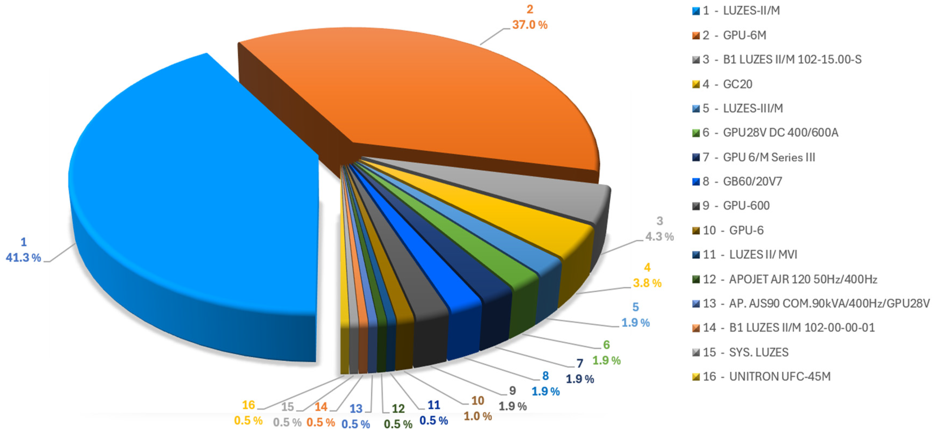
GPUs are part of an aircraft’s Ground Support Equipment (GSE). Within the inventory of the PAF, there are 28 types of GPUs, including fixed or portable units, which comprise 53% of the total, and vehicle mounted or towable units, which constitute 47%.
The PAF utilize 16 types of fixed or portable GPUs. A detailed list of these GPUs in service is presented in Table 1.
The LUZES-II/M and GPU-6M GPUs are the most numerous groups. Single units of other GPU types, other than those mentioned in Table 1, are also operated in the PAF. The percentage distribution of each GPU type is shown in Figure 1.
Table 2 presents a list of 12 types of vehicle-mounted or towable GPU units operated by the PAF.
The most common in this group are the APA-5D and LUZES V/D GPUs mounted on a JELCZ 442.32 and STAR-944 chassis. Among the 12 types of currently operated vehicle-mounted or towable GPUs, these three models make up 65% of the PAF equipment. There are also single units, other than those mentioned in Table 2, of these types of GPUs operated within the PAF. The percentage distribution of different types of vehicle-mounted or towable GPUs used by the PAF is shown in Figure 2.
Considering only the type of vehicle-mounted or towable GPUs (regardless of its transport platform), their numerical distribution is shown in Table 3, with the percentage breakdown illustrated in Figure 3. It can be observed that LUZES V comprises a substantial 71% of the inventory of the PAF, followed by APA 5D units at 23.5%, with the remaining 5.5% consisting of other GPU types.
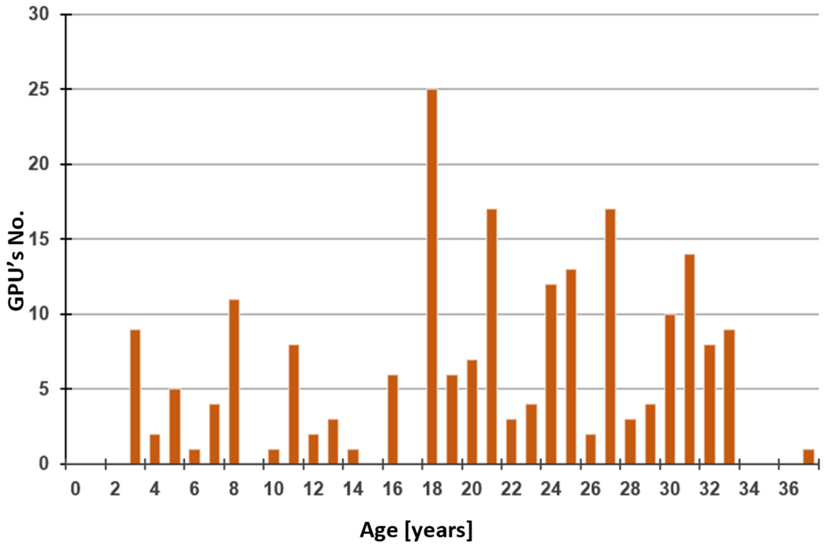
A significant factor for GPUs in use is its operational age. The aging processes that occur during the lifecycle can substantially contribute to the deterioration of the technical condition of the GPUs in use, thereby affecting the power quality they produce. The age of fixed and portable GPUs in the PAF is illustrated in Figure 4. The oldest operational GPU for this group is 37 years (one LUZES-II/M), while eight GPU-6M units have been in service for 33 years. The LUZES-II/M and GPU-6M type units also belong to the youngest group of fixed and portable GPUs used in the PAF. Additionally, in recent years, other types of GPUs have been introduced into service, including: GPU28V DC 400/600A, APOJET AJR 120 50 Hz/400 Hz, AP. AJS90 COM.90 kVA/400 Hz/GPU28V, GC20, GB60/20V7, UNITRON UFC-45M, and GPU-600.
The age of vehicle-mounted and towable GPUs is shown in Figure 5. It should be observed that the older operational GPUs reach as much as 42 years.
Three groups of GPUs can be identified based on their age:
  • First Group—ranges from 1 year to 13 years
  • Second Group—ranges from 19 to 29 years
  • Third Group—ranges from 34 to 42 years
The last group consists of 48 units, among which three of them have been in service for an impressive 42 years—one APA-5D and two LUZES V/D units mounted on the STAR 266M2 chassis.
The first age group of GPUs include, among others, the P70TA000A03-801, HOBART 4400, and LUZES-V/N, as well as LUZES V/D mounted on the JELCZ 442.32 chassis.

3.1. Statistics on Aircraft Defects Related to GPUs

During the operation of military aircraft, defects have occurred due to poor power quality or GPU failures. From 2014 to 2023, the airworthiness management IT system [1] recorded seventy-two defects or failures related to GPUs, which resulted in the aircraft being rendered unairworthy. The number of these events over the subsequent years is illustrated in Figure 6.
Figure 7 presents the number of defects and failures related to GPUs in relation to specific A/C types.
The highest number of defects or failures on the W-3WA type associated with the GPUs, shown in Figure 7, is probably due to the large population in the PAF of this type of helicopter and the high current draw from the power supply during start-up of this aircraft, which is a high requirement for power quality. Engine starting on the W-3WA helicopter is performed using an electric starter mounted directly on the engine gearbox.

3.2. Examples of Consequences of the GPU Improper Operation

The non-compliance of power quality [3] or GPU defects have led to the unairworthiness of various aircraft, including the following cases:
  • Incorrect assessment of AC EPM unit operation on SH-2G helicopters, resulting in unnecessary unit withdrawals from service.
  • Non-compliant power quality of observed onboard converters used during the ground checks of aircraft systems, e.g., radio navigation devices.
  • Illumination and extinguishing of the GPU button during the CASA C 295M engine start.
  • Loss of indications for engine parameters and circuit breakers tripped during the startup of the W-3WA helicopter.
  • Inability to power up the PZL-130TC-II aircraft.
  • Disconnection of the GP-21 GPU during the MiG-29M aircraft engine start.
  • Voltage fluctuations in the AC (Alternating Current) power supply in the onboard power supply system of the M28B aircraft.
The presented examples confirmed findings from studies conducted by the AFIT (Air Force Institute of Technology) regarding the incorrect assessment of AC EPM unit performance on SH-2G helicopters [6]. The investigations were carried out using a test setup for the AC EPM unit M24021-4 type or M24021-5 type from the SH-2G helicopter, as depicted in Figure 8.
The studies revealed that the AC EPM helicopter units declared as faulty were fully operational; however, the power quality from the GPU (used as a power source for the aircraft) did not meet the requirements [3]. This discrepancy led to the unit being taken out of service and the aircraft being unairworthy.
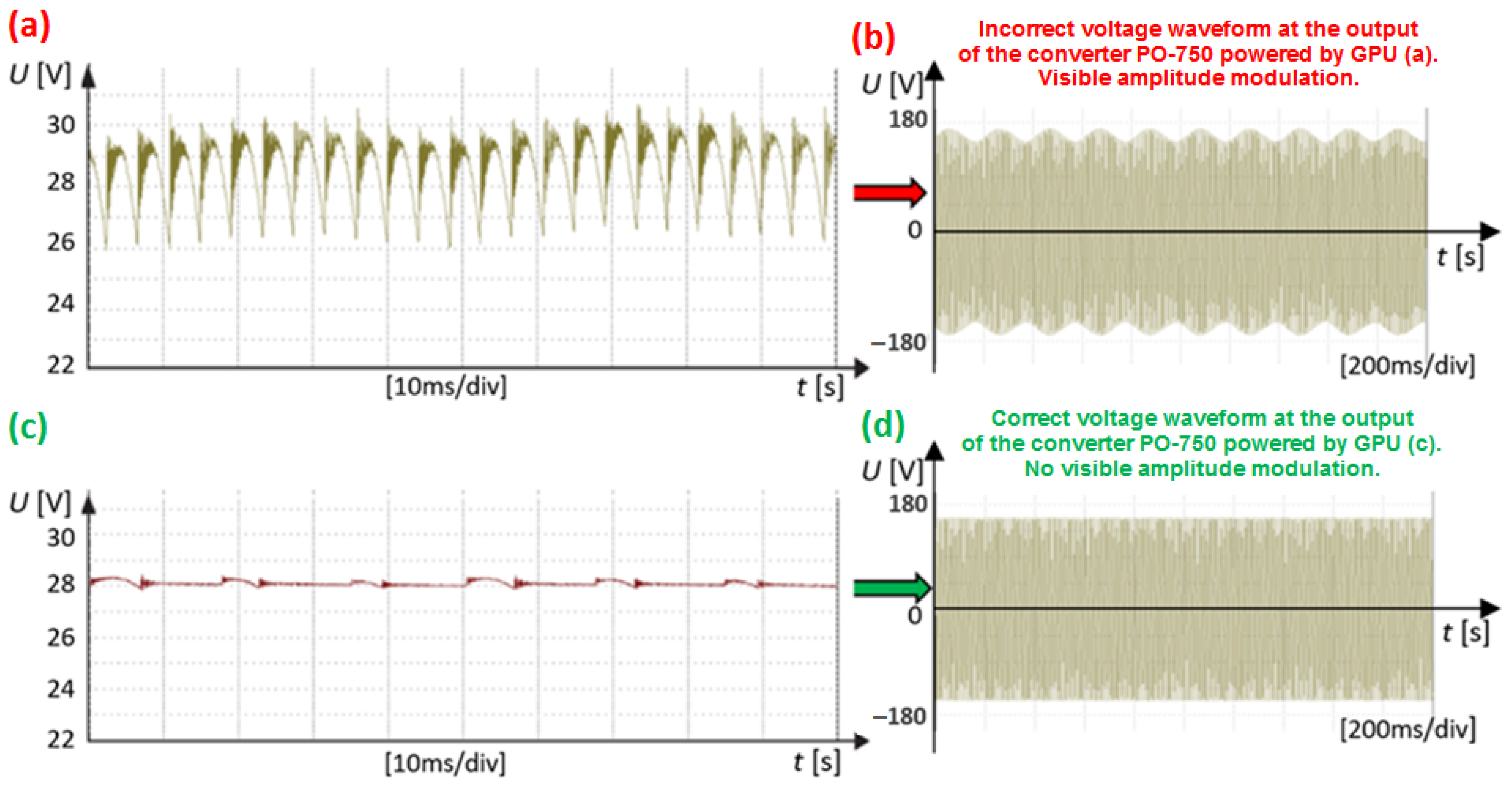
The next presented example was caused by a seemingly minor parameter: the ripple of the direct current voltage at the GPU output (Figure 9a). It turned out that this parameter significantly affects the performance of the converter, leading to noticeable amplitude modulation of the converter’s output voltage (Figure 9b). The distorted voltage from the converter negatively impacts the operation of onboard devices during aircraft maintenance and affects the reliability of checks and adjustments. In contrast, Figure 9c shows the correct waveform of the direct current voltage at the GPU output, while Figure 9d illustrates the output voltage of the converter.
Poor power quality supplied from the GPU to A/C, particularly during transients (such as overvoltage pulses, peak pulses, undervoltage pulses, and voltage instability) poses a significant risk to modern on-board systems that utilize sensitive electronic and microprocessor-based circuits [7]. In modern aviation, the reliability of on-board systems increasingly depends on the utilized GPUs [8,9,10].
The power quality supplied to A/C has a significant impact on reliability, operating costs, and safety. Poor parameters of electrical power can disrupt the operation of the A/C on-board systems, lead to shutdowns, or, in extreme cases, cause damage. Apart from constant disruptions related to the load from properly functioning systems and electrical consumers of A/C, intermediate disruptions are also significant. These disruptions can stem from failures within the power distribution system or local electrical installation of the aircraft, as well as high-power consumers, which may result from decreased reliability and durability of switching devices or activation of overcurrent protections due to repeated (long-term) circuit overloads. Sudden changes in power demand, which generate transient states in the power supply system, are particularly critical for the on-board devices and systems.

3.3. Case Study

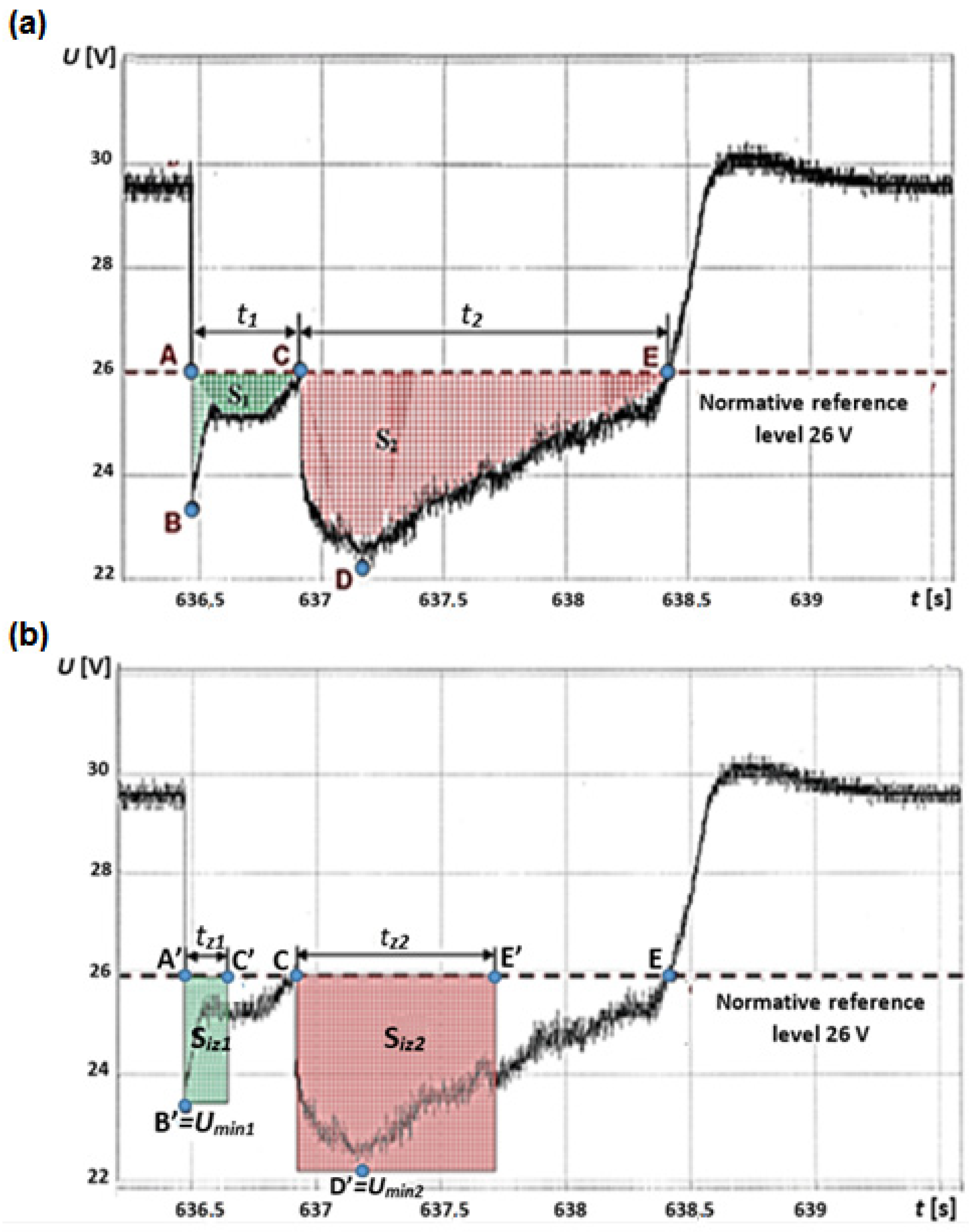
Figure 10 shows exemplary voltage waveform recorded during A/C startup from the GPU.
Typically, analyzing under- and overvoltage peaks involves calculating the value of the product of the non-standard time and voltages—specifically, the integral of voltage over time. Figure 11 provides an example of transient voltage analysis over time after a step load is applied to a DC power supply system.
According to Polish military standard [3], transient voltages are converted into their equivalent replacement peaks, which are rectangular DC voltage pulses at 28 V, matching the actual voltage pulses (Figure 11a, details: S1, S2—undervoltage peaks). The replacement peak pulse Siz (Siz2) takes the form of a rectangle with the same area and minimum voltage Umin1 (Umin2), but with a shorter duration (reduced time tz) than the actual pulse S1 (S2)—see Figure 11b, details: Siz1, Siz2.
For the transient state shown in Figure 11a, the replacement peaks (areas S1, S2 below the lower reference level of 26 V) should be calculated according to Formulas (1) and (2).
S 1 = 0 t A C 26 U t d t
S 2 = 0 t C E 26 U t d t
The reduced time tz of the replacement peaks should be calculated pursuant to Formula (3).
t z = S 29 U m i n
The parameter determined during the transient state is the value of the product of non-standard time and voltage, which is converted into the so-called replacement peak Siz according to Formulas (4) and (5).
S i z 1 = 26 U m i n 1 · t z 1
S i z 2 = 26 U m i n 2 · t z 2
These calculated pulses, shown as equivalent replacement peaks Siz in Figure 11b (a rectangle with sides: height Umin and width tz), are compared to the normative characteristics of the transient state, and their values should fall within the limits specified in the standard [3].
Based on the authors’ experience, it can be concluded that long-age operation of GPUs negatively affects the power quality from these sources. This is specifically true during their operation in transient states [11]. An example of the impact of GPUs’ age on changes in the parameters of DC power in a transient state is presented in Figure 12, which shows the visualization of test results for the DC power supply source of the Su-22 aircraft in a transient state over successive years in service.
In the subsequent years of the source’s operation, power quality parameters deteriorated until they reached non-compliant values. For this reason, older GPUs should be subjected to particularly careful verification of their technical condition, including the generated power quality, and especially the transient power parameters of the GPU.
Additionally, transient surge voltage loading of the GPU is an essential element for transient testing of 115/200 VAC GPU. Transient tests are performed by measuring the voltage AC at the end of the GPU dispensing cable during load changes, and are carried out analogously to the transient tests of a 28 VDC power circuit. However, in contrast to DC circuits, it is not the voltage waveform that is to be tested as a function of time, but the voltage envelope waveform. The time waveform u = f(t) is analyzed separately.
  • Overvoltage peaks are above 118 V.
  • Undervoltage peaks are below 112 V.
These peaks are converted into the corresponding equivalent peaks: overvoltage or undervoltage.
The peaks duration, on the other hand, is calculated by integrating the following:
  • the area between the envelope of the actual waveform u = f(t) above the 118 V level
  • the area between the envelope of the actual waveform u = f(t) below the 112 V level.
The resulting areas are divided by the amplitude of the peak, i.e.:
  • The maximum value of the envelope of the real waveform u = f(t) is above the 118 V level.
  • The minimum value of the real waveform envelope u = f(t) below the 112 V level.
The reduced value of the peak duration is thus obtained. The value of the equivalent peak is assimilated to the normative curve [3]. If at least one of the equivalent pulses of a given GPU channel crosses the normative curve, the test result is negative.

4. Discussion

4.1. Standards Analysis

Currently, a variety of GPUs are in operation in the PAF, with manufacturers of individual GPUs declaring compliance of their equipment with various standards: PN ISO6858:1997 [12], ISO6858:1982 [13], ISO6858:2017 [14], and MIL STD-704F w/CHANGE 1 [15], or only within the scope of selected parameters specified in the standards.
The analysis of the power quality requirements for GPUs according to NO 17 A206:2019 [3] and their comparison to other standards cited by GPU manufacturers showed their convergence to a large extent, but also showed existing differences, especially for transient testing.
When comparing the steady-state characteristics of the AC output (3 × 115 V voltage) specified in NO-17-A206:2019 [3], the following was found:
  • Voltage—the range is the same for standards [12,13] and smaller than within the ranges defined in standard [14] and is larger than in standard [15];
  • Phase displacement—the range is the same for standards [12,13] and smaller than within the ranges defined in standards [14,15];
  • The crest factor—the range is the same for the compared standards [12,13,14,15];
  • Total harmonic content—the range is the same for the compared standards [12,13,14,15];
  • The divergence of corresponding ordinates from those of the equivalent sine—the requirement is the same for standards [12,13] and not specified in standards [14,15];
  • AM phase voltage amplitude modulation—the range is smaller than for standards [12,13,14] and larger than specified in standard [15];
  • Effective value of phase voltage envelope harmonic modulation depth—the range is within the ranges defined in standards [12,13,14,15];
  • Frequencies—the range is the same for standards [12,13,14] and smaller for standard [15];
  • Frequency drift—the range is the same for standards [12,13] and not specified in standards [14,15];
  • Frequency modulation—the range is the same for standards [12,13,14] and larger than in standard [15].
When comparing the transient characteristics of the AC output (voltage 3 × 115 V) specified in NO-17-A206:2019 [3], for the following was found:
  • Transient surge voltages—in the case of standards [12,13,14,15], both the ranges and the way of implementing the test (defining how to load the device under test) are different;
  • Frequency transient—in the case of standards [12,13,14,15], both the ranges and the way of performing the test (determining how to load the device under test) are different.
When comparing the steady-state characteristics of the DC output (voltage 28 V) defined in NO-17-A206:2019 [3], for the following was found:
  • Voltage—the range is the same for standards [12,13] and smaller than for [14,15];
  • Voltage ripples:
    -
    the ripple of the DC supply maximum deviation from the average voltage level is smaller than in standards [12,13,14] and both different and larger than in standard [15], where the maximum amplitude of the ripple is specified
    -
    the root-mean-square (r.m.s.) values of the individual cyclic components of the ripple requirement is the same for standards [12,13,14,15];
When comparing the transient characteristics of the DC output (28 V voltage) specified in NO-17-A206:2019 [3], it was found that both the ranges and the implementation of the test are comparable for standards [12,13], while standards [14,15] differ in both the ranges and the implementation of the test.
In summary, the testing of GPUs will make it possible to determine their current state of repair in relation to the power quality requirements set out in NO 17 A206:2019 [3], and the planned comparison of the results with other standards will allow the identification of uniform requirements, or the possibility of comparing them and unambiguously interpreting the suitability of GPUs to power A/C in service in the PAF.

4.2. Proposed Tests

The general importance of norm specification and following have been mentioned, e.g., in [16]. The serviceability power supplied by the GPU to onboard A/C systems is determined by the quality requirements specified in standards [3]. By decision of the Minister of National Defence, No. 40/MON of 17 March 2020, Defence Standard NO-17-A206:2019 “Military Aircraft—Ground Power Supply Systems—Requirements” was introduced for implementation. This standard specifies, i.e., the requirements that must be met by the electrical power parameters at the end of the GPU’s output cable. Ensuring these parameters is a necessary condition for the proper operation of the A/C onboard systems. It is worth noting that the above-mentioned standard corresponds to the standard requirements commonly in force in NATO countries, meaning that GPUs compliant with this standard should guarantee their capability to service the A/C of the PAF.
In accordance with the NO-17-A206:2019 standard [3], testing the power quality of GPUs should be performed in steady and transient states for the following:
  • Characteristics of the AC Power Supply System
  • Characteristics of the DC Power Supply System
The authors suggest that to reliably assess the power quality in both steady and transient states, a specific set of tests is required. These tests, aligned with the NO-17-A206 standard [3] and within the GPU’s manufacturer-declared power capacity, are both necessary and sufficient. Importantly, they are designed to ensure the GPU operates safely without risk of overload or malfunction.
The scope of GPU testing for the DC output cable should include the following:
  • For steady state at load levels of 0%, 5%, and 85% of rated power:
    • Steady-state voltage value
    • Amplitude of voltage ripple component
    • Frequency analysis of harmonic content in the ripple component
  • For transient states during load changes from 5% to 85% and from 85% to 5% of rated power:
    • Overvoltage peak parameters
    • Undervoltage peak parameters
The scope of GPU Testing for the AC output cable should include the following:
  • For a steady state at load levels of 0%, 5%, 85% of rated power:
    • Steady-state voltage value
    • Steady-state frequency
    • Harmonic content
    • Amplitude modulation depth of the voltage
    • Voltage asymmetry
    • Frequency drift
  • For transient states during load changes from 5% to 85% and back from 85% to 5% of rated power:
    • Overvoltage peak parameters
    • Undervoltage peak parameters
    • Transient state frequency parameters

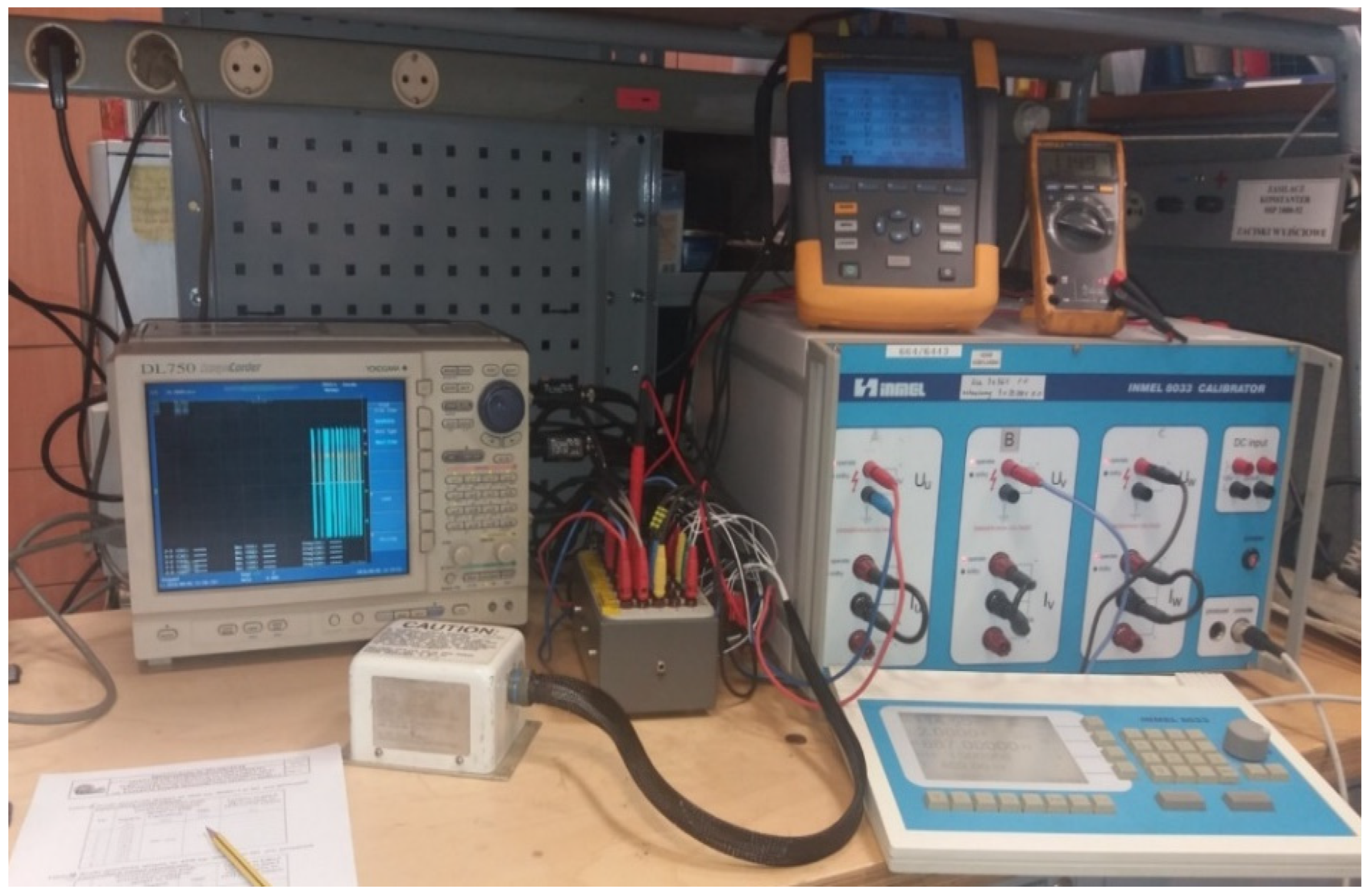
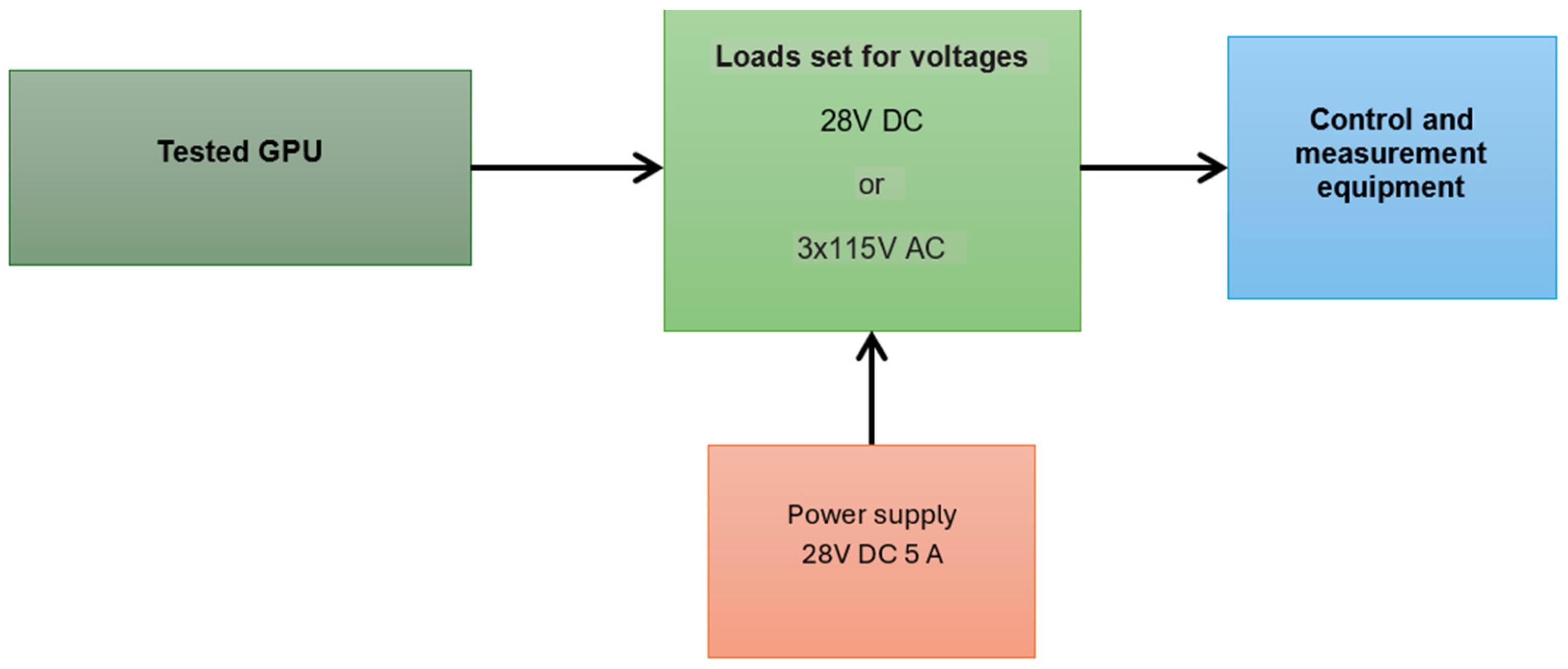
5. Methodology Verification

Power quality tests of GPUs performed by the authors are carried out on the test bench shown in Figure 13.
The GPU power quality test bench consists of a load set equipped with an aerial connector that allows the plug of the dispensing cable of the GPU under test to be connected. Depending on the type of the GPU under test, the test bench is equipped with a load set for 3 × 115 V AC voltages or a 28 V DC load set (Figure 13). An external 28 V DC power supply is connected to control the operating contactors of the load set. The control and measurement equipment are connected to the laboratory sockets of the load set.
The control and measurement equipment consists of the following:
  • DC ammeter→2500 A, 2%
  • AC ammeter→390 A, 2%
  • Voltmeter→AC/DC, 400 Hz, 200 V, 1%
  • Harmonic analyzer→THD, 250 V
  • Power analyzer→3 phase, 2%
  • Voltage recorder→8 channels DC/AC 250 V, 4 channels RMS 250 V, 20 ks/s.
  • Oscilloscope→4 channels 250 V
  • Frequency recorder→1 channel 400 Hz, 115 V
The comparative results presented below show how the proposed methodology effectively identifies the GPU with different lifetimes in relation to the power quality requirements of the standard [3]. The comparison presented is for a GPU with the same power rating operated for 4 years (No. 1) and for 20 years (No. 2). Values obtained that do not comply with the requirements of the standard [3] are written in bold.
Example test results for GPU No. 1 and No. 2 at the end of a 28 V DC dispatch cable in steady state obtained with rated currents of 0% Iz, 5% Iz, and 85% Iz are shown in Table 4, Table 5 and Table 6.
The transient tests of GPU No. 1 and No. 2 were performed by loading the GPU device at the end of a 28 V DC dispensing cable with a current of 5% Iz and then pulse-loading the device with a current of 85% Iz. The 85% Iz current was held for about 5 s and the GPU load was reduced to 5% Iz.
Example results from testing GPU No. 1 and No. 2 at the transient end of the 28 V DC dispensing cable are shown in Table 7.
Example test results for GPU No. 1 and 2 at the end of a 3 × 115 V AC release cable in a steady state obtained with 0% Iz, 5% Iz, and 85% Iz rated current are shown in Table 8, Table 9, Table 10, Table 11, Table 12 and Table 13.
The GPU transient tests were carried out by loading the GPU at the end of a 3 × 115 V AC distribution cable with a current of 5% Iz, and then the device was pulse-loaded with a current of 85% Iz. The 85% Iz current was then held for approximately 5 s, and the GPU load was reduced to 5% Iz. Example results for GPU No. 1 and No. 2 at the end of a 3 × 115 V AC distribution cable transient are shown in Table 14 and Table 15. Non-conforming values are written in bold.

6. Conclusions

The power quality supplied by the GPU has a significant impact on reliability, costs, and the operation safety of A/C.
The GPUs operated by the PAF are highly diverse in terms of type and age. It is essential to identify individual GPUs and assess their current technical condition with regard to the normative requirements for power quality. It should be underlined that the military units operating aircraft do not possess tools for automated, comprehensive assessment (in steady and transient states) of the power quality supplied by the GPUs. The airport control devices LUK-1 (DC) and LUK-2 (AC), developed at AFIT in the 1990s, which enabled comprehensive diagnostics of GPUs in steady and transient states, have been withdrawn from service. Therefore, it is necessary to establish a unified system for monitoring the power quality of GPUs in the PAF in accordance with the NO-17-A206:2019 [3] standard.
Due to this, AFIT has initiated work that will ultimately create the possibility of developing airport control devices that enable automatic measurements and serve as the basis for implementing a system for a comprehensive assessment of the power quality supplied by GPUs. The implementation of these devices into operation in the PAF, along with the training of technicians to use them during regular airport operations, will enable ongoing monitoring of the power quality supplied by GPUs. This will enhance the operational readiness of GPUs supporting aircraft in the PAF, resulting in greater reliability and safety in operations.

Author Contributions

Conceptualization, T.T., S.M. and T.P.; methodology, T.T.; software, T.T.; validation, T.T. and S.M.; formal analysis, T.T. and S.M.; investigation, T.T.; resources, B.K., M.Z. and T.P.; data curation, T.T. and B.K.; writing—original draft preparation, T.T.; writing—review and editing, S.M. and B.K.; visualization, T.T. and B.K.; supervision, S.M., M.Z. and T.P. All authors have read and agreed to the published version of the manuscript.

Funding

This research received no external funding.

Data Availability Statement

Data are contained within the article.

Conflicts of Interest

The authors declare no conflicts of interest.

Abbreviations

The following abbreviations are used in this manuscript:
ACAlternating Current
A/CAircraft
AFITAir Force Institute of Technology
ASSLAbnormal steady-state limits
DCDirect Current
EPMExternal Power Monitor
ESSLEmergency steady-state limits
GPUGround Power Unit
IAWIn accordance with
NATONorth Atlantic Treaty Organization
NSSLNormal steady-state limits
PAFPolish Armed Forces
r.m.s.Root-mean-square
THDTotal harmonic distortion

References

  1. Pigłas, M.; Radoń, T.; Szymański, M.; Krutkow, A.; Przystawska, A. Information system support for military aircraft operations SI SAMANTA as a tool to support logistic resource management. J. KONBiN 2020, 50, 269–286. [Google Scholar] [CrossRef]
  2. Gębura, A.; Setlak, L.; Tokarski, T.; Borowski, J. (Eds.) Lotnicze Urządzenia Elektryczne: Monografia; Wydawnictwo Instytutu Technicznego Wojsk Lotniczych: Warszawa, Poland, 2023. [Google Scholar]
  3. Norma Obronna NO-17-A206:2019; Wojskowe Statki Powietrzne—Naziemne Układy Zasilania Elektroenergetycznego. Podstawowe Parametry, Wymagania i Badania. Zatwierdzona Decyzją nr 117/MON Ministra Obrony Narodowej z Dnia 29 Lipca 2019 r. (Dz. Urz. Min. Obr. Nar. Poz. 145). 2019.
  4. Ministerstwo Obrony Narodowej. Dowództwo Generalne Rodzajów Sił Zbrojnych. Instrukcja zarządzania eksploatacją sprzętu wojskowego w Siłach Zbrojnych Rzeczypospolitej Polskiej. Zasady Ogólne 2018, DU-4.22.13.
  5. Lewitowicz, J. Systemy Eksploatacji Statków Powietrznych; Podstawy Eksploatacji Statków Powietrznych; Wydawnictwo Instytutu Technicznego Wojsk Lotniczych: Warszawa, Poland, 2006. [Google Scholar]
  6. Michalak, S.; Tokarski, T.; Kalisiak, M. Ocena stanu technicznego agregatów zabudowanych na śmigłowcu SH-2G Kontroler zasilania prądem przemiennym (AC EXTERNAL POWER MONITOR TYPU M24021-4 i M24021-5). Biul. Tech. ITWL (1983/I) 2018. [Google Scholar]
  7. Aguida, M.E.; Che, Y.; Yang, J. Technological Advancements and Future Prospects of Electrical Power Systems for Sustainable More Electric Aircraft. Propuls. Power Res. 2024, 13, 475–486. [Google Scholar] [CrossRef]
  8. Danilecki, S.; Tkaczuk, S. Eksploatowanie samolotów jako dyscyplina wiedzy po 100 latach doświadczeń. Biul. WAT 2015, 64, 13–23. [Google Scholar] [CrossRef]
  9. Sarlioglu, B.; Morris, C.T. More Electric Aircraft: Review, Challenges, and Opportunities for Commercial Transport Aircraft. IEEE Trans. Transp. Electrif. 2015, 1, 54–64. [Google Scholar] [CrossRef]
  10. Zhao, X.; Guerrero, J.M.; Wu, X. Review of Aircraft Electric Power Systems and Architectures. In Proceedings of the 2014 IEEE International Energy Conference (ENERGYCON), Cavtat, Croatia, 13–16 May 2014; IEEE: Piscataway, NJ, USA, 2014; pp. 949–953. [Google Scholar] [CrossRef]
  11. Tokarski, T. Evaluation of Direct Current Electric Power Systems of the Aircraft Based on Characteristics of a Transient State. Diagnostyka 2018, 20, 81–91. [Google Scholar] [CrossRef]
  12. PN-ISO6858:1997; Naziemne Źródła Zasilania Energią Elektryczna. Wymagania Ogólne. Polish Committee for Standardization: Warsaw, Poland, 1997.
  13. ISO6858:1982; Aircraft—Ground Suport Electrical Supplies—General Requirements. ISO: Geneva, Switzerland, 1982.
  14. ISO6858:2017; Aircraft—Ground Suport Electrical Supplies—General Requirements. ISO: Geneva, Switzerland, 2017.
  15. MIL-STD-704F w/CHANGE 1:2016; Aircraft Electric Power Characteristics. United States Department of Defense: Arlington County, VA, USA, 2016.
  16. Wilson, P.R. Advanced Aircraft Power Electronics Systems—The Impact of Simulation, Standards and Wide Band-Gap Devices. Trans. Electr. Mach. Syst. 2017, 1, 72–82. [Google Scholar] [CrossRef]
Figure 1. The percentage distribution of each type of fixed or portable GPUs operated by the PAF (numbered according to Table 1).
Energies 18 01945 g001
Figure 2. The percentage distribution of each type of vehicle-mounted or towable GPUs operated by the PAF (numbered according to Table 2).
Energies 18 01945 g002
Figure 3. The percentage distribution of various vehicle-mounted or towable GPUs, excluding transport type (numbering according to Table 3).
Energies 18 01945 g003
Figure 4. Age of fixed and portable GPUs in the PAF.
Energies 18 01945 g004
Figure 5. Age of vehicle-mounted and towable GPUs in the PAF.
Energies 18 01945 g005
Figure 6. The number of defects or failures of aircraft (A/C) related to GPU.
Energies 18 01945 g006
Figure 7. The number of defects and failures of specific A/C types related to GPU.
Energies 18 01945 g007
Figure 8. Testing station at the Air Force Institute of Technology (AFIT) for the AC EPM unit type M24021-4 or M24021-5 from the SH-2G helicopter [6].
Energies 18 01945 g008
Figure 9. Voltage waveforms from GPU and from the powered converter: (a) incorrect power quality from GPU, (b) incorrect power quality from the converter powered from GPU, (c) correct power quality from GPU, (d) correct power quality from the converter powered from GPU.
Energies 18 01945 g009
Figure 10. Transient states and spike pulses of 28 VDC in the exemplary A/C start-up from GPU.
Energies 18 01945 g010
Figure 11. Example analysis of the 28 V waveform while testing the transient state of a DC power system (based on [3]): (a) A-B-C and C-D-E—voltage waveform curves over time—transient state (undervoltage peak), (b) areas of the replacement undervoltage peaks (A’-B’ and C’-D’ height Umin and, respectively, A’-C’ and C’-E’ width tz); S1, S2—area under the actual waveform below the reference level of 26 V; Siz1, Siz2,—equivalent replacement peaks of the actual waveform.
Energies 18 01945 g011
Figure 12. Illustration of test results of the Su-22 aircraft DC power supply in transients during successive years of operation.
Energies 18 01945 g012
Figure 13. Block diagram of the GPU power quality test bench.
Energies 18 01945 g013
Table 1. List of fixed or portable ground power units (GPU) operated by the Polish Armed Forces (PAF).
No.GPU NAME (Type)Number of Vehicles Operated in the PAF
1.LUZES-II/M Ground Power Unit86
2.GPU-6M Ground Power Unit77
3.B1 LUZES II/M 102-15.00-S container9
4.GC20 Ground Power Unit8
5.LUZES-III/M Ground Power Unit4
6.GPU28V DC 400/600A Ground Power Unit4
7.GPU 6/M Series III Ground Power Unit4
8.GB60/20V7 Ground Power Unit4
9.GPU-600 Solid State Ground Power Unit4
10.GPU-6 Ground Power Unit2
11.LUZES II/MVI Ground Power Unit1
12.APOJET AJR 120 50 Hz/400 Hz Ground Power Unit1
13.AP. AJS90 COM.90 kVA/400 Hz/GPU28V Ground Power Unit1
14.B1 LUZES II/M 102-00-00-01 container1
15.SYS. LUZES electro-energetic device set1
16.UNITRON UFC-45M Ground Power Unit1
Table 2. A list of vehicle-mounted or towable GPUs operated by the PAF.
No.GPU NAME (Type)Number of
Vehicles Operated in the PAF
1.APA-5D Ground Power Unit44
2.LUZES V/D on the JELCZ442.32 Ground Power Unit44
3.LUZES V/D Ground Power Unit on the STAR-944 vehicle35
4.LUZES-V/D Ground Power Unit on the STAR-266M2 vehicle21
5.LUZES-V/N Ground Power Unit17
6.LUZES-V/D Ground Power Unit on the STAR-744 vehicle14
7.P70TA000A03-801 Ground Power Unit6
8.CUMMINS QSB DIESEL 90CU420 generator2
9.HOBART 4400 Ground Power Unit2
10.LUZES V/N S. 3 Ground Power Unit1
11.EINSA Ground Power Unit1
12.LUZES V/D on the STAR 742 Ground Power Unit1
Table 3. A list of vehicle-mounted or towable GPUs, excluding transport type.
No.GPU NAME (Type)Number of Vehicles Operated in the PAF
1.LUZES V Ground Power Unit in D and N Series133
2.APA-5D Ground Power Unit44
3.P70TA000A03-801 Ground Power Unit6
4.HOBART 4400 Ground Power Unit2
5.CUMMINS QSB DIESEL 90CU420 generator2
6.EINSA Ground Power Unit1
Table 4. Voltage, NO-17-A206: 2019 [3] p. 2.4.2.1.
No.GPU LoadGPU No. 1GPU No. 2Required Value
U [V]
1.0% Iz28.4628.1726 ÷ 29 V
2.5% Iz28.4727.40
3.85% Iz28.5124.05
Table 5. DC voltage ripple, NO-17-A206: 2019 [3] p. 2.4.2.2.
No.GPU LoadGPU No. 1GPU No. 2Required ValueGPU No. 1GPU No. 2
Upmax [V]5% of Mean Voltage [V]
1.0% Iz0.7350.674<5% of mean voltage1.4231.409
2.5% Iz1.0910.9981.4241.370
3.85% Iz1.3861.2531.4261.203
Table 6. Frequency analysis of harmonic content in the ripple component, NO-17-A206: 2019 [3] p. 2.4.2.3.
No.GPU LoadGPU No. 1GPU No. 2Required Value
Urms [V]f [Hz]5% of Mean Voltage [V]
1.0% Iz0.0257.2080.04572.71IAW Figure 12 [3]
2.5% Iz0.1184799.730.1362400.14
3.85% Iz0.0824799.860.1152402.28
Table 7. DC transient characteristics, NO-17-A206: 2019 [3] p. 2.4.3.1.
No.GPU LoadGPU No. 1GPU No. 2Required Value
U [V]t [s]tz [s]U [V]t [s]tz [s]
1.Overvoltage peak (5% ÷ 85%) Iz20.600.00560.003422.873.4602.1626IAW Figure 15 [3]
2.Undervoltage peak (5% ÷ 85%) Iz33.600.02830.0168No exceedance
noticed
Table 8. Voltage, NO-17-A206: 2019 [3] p. 2.3.2.1.
No.GPU LoadGPU No. 1GPU No. 2Required Value
U [V]
ABCABC
1.0% Iz115.12115.12115.11115.53115.56115.55112 ÷ 118 V
2.5% Iz114.95114.98114.99115.45115.49115.49
3.85% Iz114.30114.74115.01114.95116.20116.49
Table 9. Voltage asymmetry, NO-17-A206: 2019 [3] p. 2.3.2.3.
No.GPU LoadGPU No. 1GPU No. 2Required Value
U [V]
A-BB-CC-AA-BB-CC-A
1.0% Iz0.000.010.000.030.000.02<3 V
2.5% Iz0.020.000.030.030.000.04
3.85% Iz0.430.270.711.310.231.54
Table 10. Amplitude modulation depth of the voltage, NO-17-A206: 2019 [3] p. 2.3.2.4.
No.GPU LoadGPU No. 1GPU No. 2Required Value
The Crest Factor ka [-]
ABCABC
1.0% Iz1.421.421.421.411.401.411.31 ÷ 1.51
2.5% Iz1.421.421.421.411.401.41
3.85% Iz1.411.411.421.401.391.39
Table 11. Harmonic content, NO-17-A206: 2019 [3] p. 2.3.2.4.
No.GPU LoadGPU No. 1GPU No. 2Required Value
THD [%]
ABCABC
1.0% Iz0.570.570.572.002.002.00<5%
2.5% Iz0.560.540.552.002.002.00
3.85% Iz0.700.780.655.15.34.7
Table 12. Frequency, NO-17-A206: 2019 [3] p. 2.3.2.6.
No.GPU LoadGPU No. 1GPU No. 2Required Value
f [Hz]f [Hz]
1.0% Iz400.22400.03390 ÷ 410 Hz
2.5% Iz400.06400.04
3.85% Iz400.07399.98
Table 13. Frequency drift, NO-17-A206: 2019 [3] p. 2.3.2.7.
No.GPU LoadGPU No. 1GPU No. 2Required Value
Phase A
Fwmin [Hz]Fwmax [Hz]δ [Hz/min]Fwmin [Hz]Fwmax [Hz]δ [Hz/min]
1.0% Iz399.96400.400.550399.57400.922.091Frequency variation shall not exceed ±5 Hz and frequency drift shall not exceed 15 Hz/min
2.5% Iz399.75400.250.369399.49401.4610.74
3.85% Iz399.67400.390.923398.96401.336.91
Table 14. AC transient characteristics, NO-17-A206: 2019 [3] p. 2.3.3.1.
No.GPU LoadGPU No. 1GPU No. 2Required Value
U [V]t [s]tz [s]U [V]t [s]tz [s]
1.Overvoltage peak (5% ÷ 85%) IzNo exceedance
noticed
110.60.2240.120IAW Figure 7 [3]
2.Undervoltage peak (5% ÷ 85%) IzNo exceedance
noticed
123.40.2240.069
Table 15. Transient state frequency, NO-17-A206: 2019 [3] p. 2.3.3.2.
No.GPU LoadGPU No. 1GPU No. 2Required Value
U [V]t [s]U [V]t [s]
1.Overvoltage peak (5% ÷ 85%) IzNo exceedance
noticed
372.970.5788IAW Figure 10 [3]
2.Undervoltage peak (5% ÷ 85%) IzNo exceedance
noticed
425.580.3057
Disclaimer/Publisher’s Note: The statements, opinions and data contained in all publications are solely those of the individual author(s) and contributor(s) and not of MDPI and/or the editor(s). MDPI and/or the editor(s) disclaim responsibility for any injury to people or property resulting from any ideas, methods, instructions or products referred to in the content.

