Article

Effect of Annealing Temperature on the Microstructural and Mechanical Properties of Wire Rod Steel Annealed Using a Biomass Gasifier

by
Pathompong Chootapa
1,
Songkran Wiriyasart
2 and
Sommas Kaewluan
1,*
1
Biofuel and Bioenergy Technology Research and Development Laboratory (BBT R&D), Department of Mechanical Engineering, Faculty of Engineering, Srinakharinwirot University, 63 Rangsit-Nakhonnayok Rd., Bangkok 26120, Thailand
2
Thermal Solution and Energy Technology Research and Development Laboratory (TSET R&D), Department of Mechanical Engineering, Faculty of Engineering, Srinakharinwirot University, 63 Rangsit-Nakhonnayok Rd., Bangkok 26120, Thailand
*
Author to whom correspondence should be addressed.
Energies 2025, 18(8), 1912; https://doi.org/10.3390/en18081912
Submission received: 31 January 2025 / Revised: 1 April 2025 / Accepted: 5 April 2025 / Published: 9 April 2025
(This article belongs to the Section A4: Bio-Energy)

Abstract

Natural and liquefied petroleum gases are widely used in industrial heat treatment. However, the rising cost of gas, combined with increased demand, has significantly impacted production costs and the environment. The annealing process typically relies on natural or liquefied petroleum gases as the primary heat source. In this study, we aimed to investigate the use of biomass fuel as a replacement for fossil fuels and to evaluate the mechanical properties and microstructure of wire rod steel after annealing using indirect heat from a gasifier. We experimented to examine the effects of annealing temperatures of 650 °C, 700 °C (below the critical temperature Ac1), and 750 °C (above Ac1 but below the upper temperature Ac3). The batch furnace, made of stainless steel, was modified from a traditional wire annealing furnace that originally used CNG and LPG gas burners. It was adapted into a wire annealing furnace connected to a cross-draft gasifier. The furnace’s interior was designed with spiral cooling fins to minimize energy consumption and shorten annealing time. Additionally, it was modified to use biomass as a substitute fuel, reducing environmental pollution. The furnace was coated with thermal insulation, and the biomass gasifier stove was a cross-draft device with primary air feeding at 20 m3/h and secondary air supplied at a constant flow rate of 32 m3/h, 36 m3/h, or 40 m3/h. As a fuel source, we used eucalyptus. The mechanical properties of wire rod steel were measured in terms of tensile strength and torsion, following the TIS 138-2562 standard. This standard specifies that the tensile strength must be at least 260 MPa. Regarding torsion, the TIS 138-2562 requirements state that the wire must withstand at least 75 rounds of twisting without breaking. Our results showed that after annealing at 650 °C, 700 °C, or 750 °C, with a soaking time of 30 min and subsequent cooling in the furnace at natural temperature for 24 h, the tensile strength values were 494.82, 430.87, and 381.33 MPa, respectively. The torsion values were 126.92, 125.8, and 125.76 rounds, respectively. Additionally, ferrite grain size increased with annealing temperature, reaching a maximum of 750 °C. The total annealing duration for each batch was 2 h and 40 min at 650 °C, 2 h and 10 min at 700 °C, and 2 h at 750 °C.

1. Introduction

Wire rod is a product of low-carbon steel. Its size can be reduced and its diameter changed using a cold working process. An annealing process may then be used to improve its properties. The purposes of annealing include softening, improving machinability, refining grain size, increasing ductility, reducing residual stresses, and producing a specific microstructure. The type of annealing heat treatment depends on the procedure and temperature used. Annealing processes include normalizing, spheroidizing, sub-critical annealing, and stress relief annealing. The annealing process consists of three major steps. The first step is heating, where the steel is heated to the required critical temperature. The second step is soaking, where the temperature is maintained at the breaking point. The final step is cooling, where the steel is slowly cooled until the desired properties are achieved. The process can be refined by adjusting annealing parameters, such as temperature and soaking time, which impact mechanical properties. Increasing annealing temperature and soaking time and decreasing temperature result in lower yield strength, impact toughness, and ultimate tensile strength in low-carbon steel [1,2].
A heat treatment furnace consists of a batch and a continuous furnace [3]. The annealing process is primarily conducted in batch furnaces. The heat sources used are electricity, compressed natural gas (CNG), or liquefied petroleum gas (LPG) [4]. These are standard fuels commonly used in industrial annealing processes. Industrial methods for annealing wire rod steel include induction annealing, where electromagnetic induction heats the wire quickly and efficiently; electrical resistance annealing, where an electric current is passed through the wire to generate heat internally; and biomass-fueled annealing, an eco-friendly method in which biomass combustion is used as a heat source. Energy consumption in Thailand has increased, leading to rising costs. To address this, the government aims to increase the share of renewable energy to 30% by 2037. Regarding global energy consumption, renewable energy is expected to account for 58% of total renewables deployment by 2050, with variable renewable energy comprising 60% of total power generation, up from around 10% today [5]. At present, biomass sources such as fuelwood, agricultural waste, and charcoal account for 6.69% of Thailand’s thermal energy production. These sources produce heat energy and can readily replace fossil fuels through gasification [6,7]. Gasification is the thermal conversion of organic mass with a limited oxygen supply, generating heat and synthetic gas through biomass combustion [8,9]. The thermal process includes combustion, reduction, pyrolysis, and drying [8,10]. Direct combustion is the most common method for converting biomass into useful energy [8,11]. In this process, biomass is burned to produce heat, which is used to power industrial processes and generate electricity in steam turbines, burners, boilers, and internal combustion engines. Biomass is also used industrially as a supplementary fuel in facilities, such as sugar factories and biomass power plants. The type of biomass must have a sufficiently high heating value to replace fossil energy. This heating value depends on chemical and physical properties such as moisture content, size, and density. Previous experimental research has studied the efficiency of synthetic fuel gas and heat production about factors such as stove design, raw material selection, process control, biomass properties, and the effects of gasification on thermal efficiency [9,11,12]. Using biomass gas for annealing instead of CNG or LPG offers the advantage of lower fuel costs, as raw materials such as wood scraps, sawdust, and rice husks are cheaper than CNG and LPG, reducing production costs [13,14]. Moreover, biomass gas combustion emits fewer greenhouse gases than fossil fuels, minimizing its impact on global warming and promoting the use of renewable resources [15,16].
A case study of a factory using a batch furnace for annealing, with CNG and LPG as heat sources, found that annealing 2240 kg of wire rod steel requires an average of 140 kg of CNG or 130 kg of LPG per batch. The fuel costs per batch are 1791.11 THB for CNG and 2404.22 THB for LPG. The heating values of CNG and LPG are 52.3 MJ/kg and 45.5 MJ/kg, respectively, with market prices of 12.74 THB/kg for CNG and 18.13 THB/kg for LPG. Meanwhile, biomass sources, such as eucalyptus wood, cost 3 THB/kg. Although biomass has a lower heating value, it is a more affordable and widely available alternative. Waste wood from branches and leftover pallet production materials can also be utilized.
In addition, the greenhouse gas emission standards for industrial factories, as established by the US EPA, set the allowable limits for CO and NOx emissions at 690 ppm and 200 ppm, respectively. Industrial factories in Thailand also adhere to these standards. The emission factors for CNG and LPG are 2.26 kgCO2eq/unit and 3.11 kgCO2eq/unit, respectively (IPCC Vol.2, Table 2.2, DEDE (LPG: 1 L = 0.54 kg), IPCC Vol.2, Tables 3.2.1 and 3.2.2, PTT) [17,18]. In comparison, the emission factor for fuelwood is significantly lower at 0.0304 kgCO2eq/unit (IPCC Vol.2, Table 2.2, DEDE) [17,18]. This suggests that fuelwood has a lower environmental impact than fossil fuel gases and can generate a high gas yield through gasification. This differs from previous studies, which have primarily focused on converting biomass into bio-oil rather than utilizing it in heat treatment processes, such as annealing [17,18]. Additionally, the advantages of biomass energy sources identified in this study align with previous research, such as Pan et al. [19] and Shao et al. [20], who propose environmentally friendly and efficient approaches to utilizing biomass.
This investigation aimed to study the effects of annealing temperature on the mechanical properties of wire rod steel annealed using a biomass gasifier and determine the best operational parameters. In this study, a traditional wire annealing furnace that used CNG and LPG gas burners was modified into a wire annealing furnace connected to a cross-draft gasifier, which was adapted to use biomass as a substitute fuel to reduce environmental pollution. The furnace’s interior was designed with spiral cooling fins to minimize energy consumption and shorten annealing time. The biomass used to produce heat energy included raw materials available in the factory and surrounding areas, such as tree branches. Using biomass can help reduce energy costs for industrial plants. Additionally, pollution and waste from the gasification process are reduced as they are byproducts of incomplete combustion. This study used a cross-draft gasifier to produce synthetic gas. The research also examined the health and environmental impacts of biomass fuel, including its potential to reduce manufacturing costs for industrial plants.

2. Method

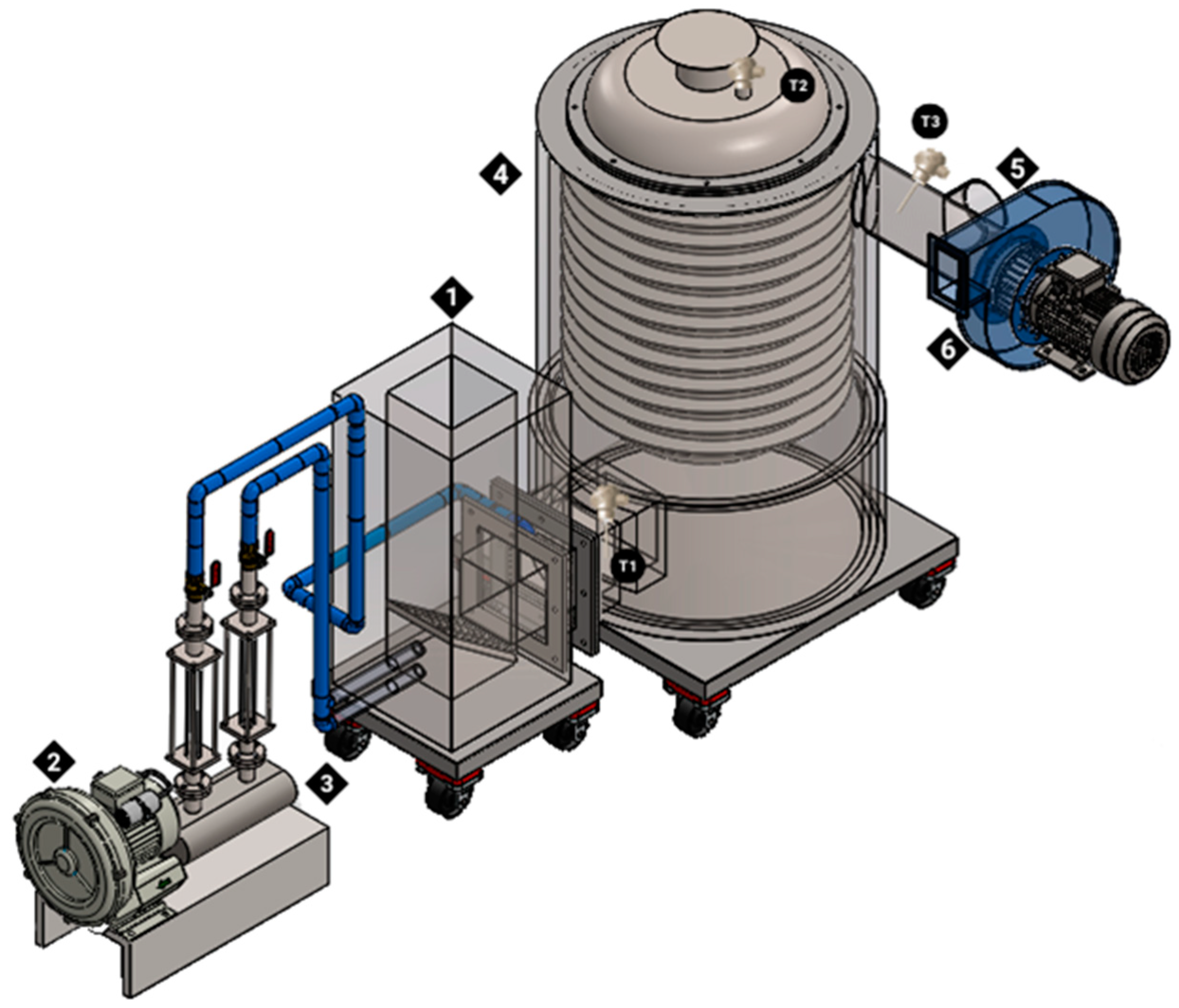
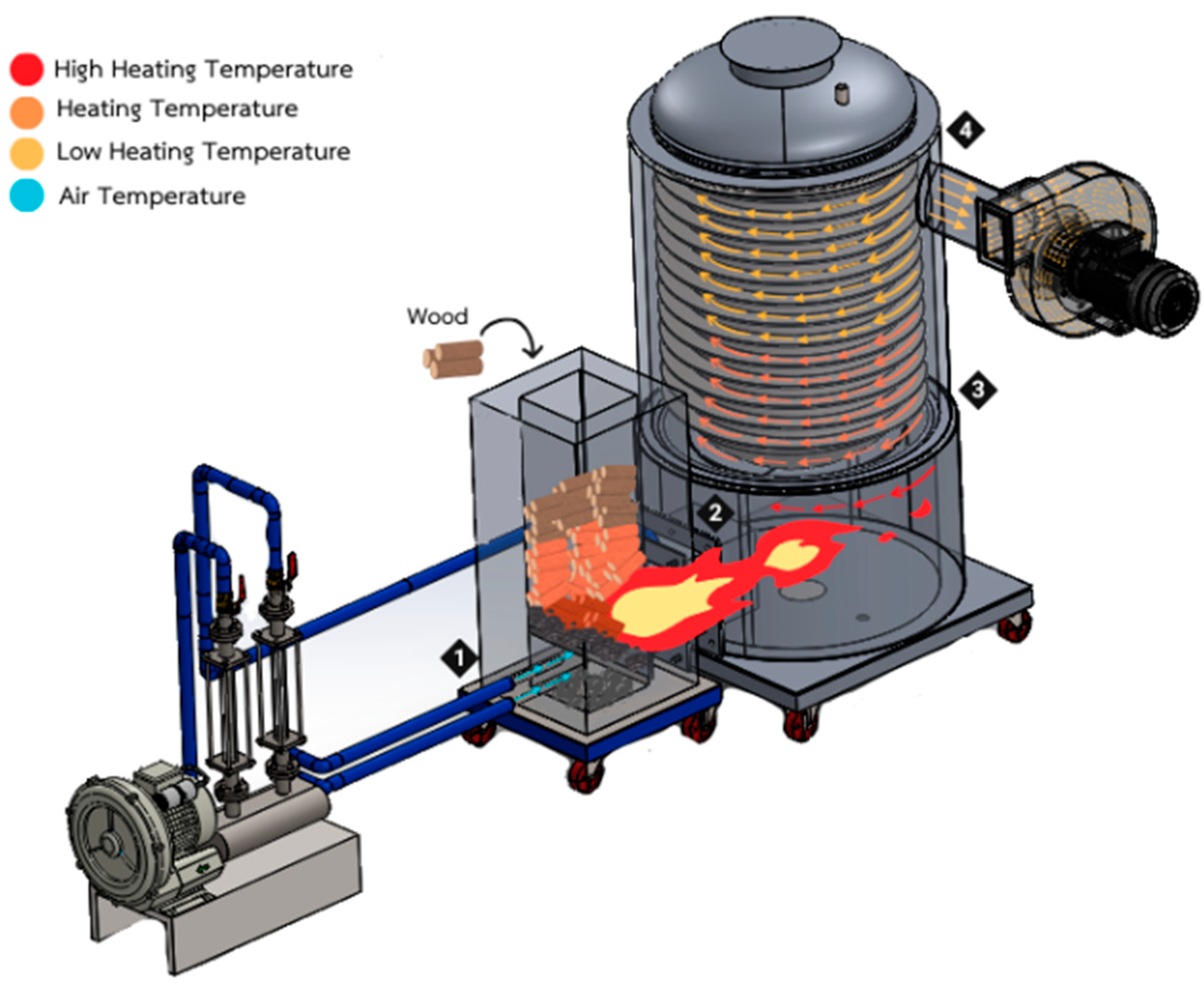
2.1. Experimental Equipment

Figure 1 illustrates the gasifier furnace experiment. The factors influencing the gasification process are the fuel and air supply. In this experimental setup, a rotameter (No. 3) is used to control the airflow in two sections through an air pump (No. 2). In the first section, primary air is supplied through two pipes, each with a diameter of 6.72 cm, into the pyrolysis zone. In the second section, secondary air is supplied through a single pipe of the same diameter into the throat area, which connects the gasifier furnace (No. 1) to the reactor (No. 4) to increase the flame temperature. The heat generated from the gasification process is drawn into the reactor by a rotary blower (No. 6) at the outlet and is then released into the atmosphere. The temperature inside the furnace and stove is measured using K-type thermocouples at three locations: the throat (T1), the top of the furnace (T2), and the exhaust (T3). The data are recorded in a Wisco data logger throughout the entire experiment, from start to finish. After the annealing process, the annealed wire is tested for its mechanical properties, including tensile strength, using a universal testing machine. A wire sample with a gauge length of 90 mm and a diameter of 0.9 mm is used for the test. Torsion testing is conducted using a manual torsion testing machine. For microstructural analysis, an optical microscope is used. The specimen undergoes rough and fine polishing with a metallographic specimen polishing machine before being etched with 2% nitric acid. After cleaning, the specimen is ready for microscopic examination and structural comparison.

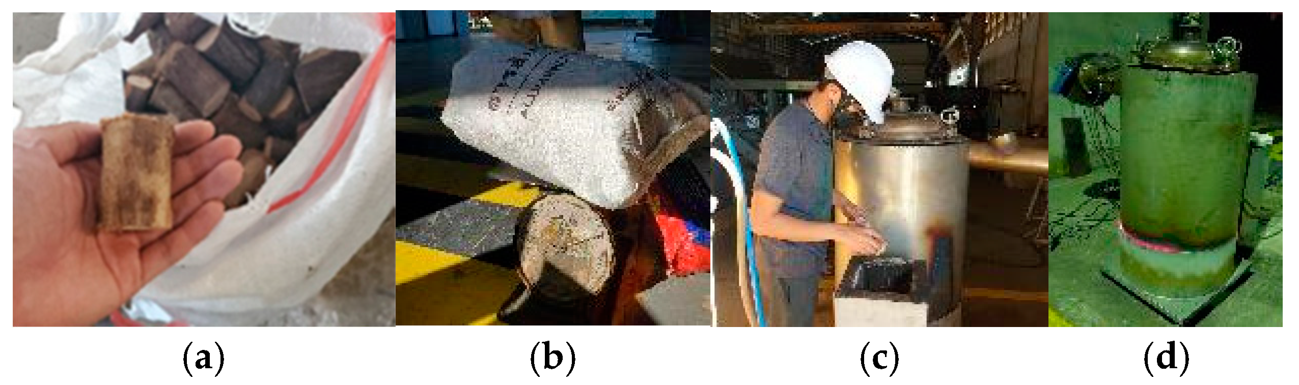
2.2. Material Method

Wire steel in its initial state before cold drawing and annealing has the same chemical and mechanical properties. Before annealing, the chemical composition of the wire rod is as follows: C—0.17%, Mn—0.3%, P—0.04%, S—0.04%, and Cr (wt%). However, copper (Cu) is not a primary alloying element and is typically present in very low amounts, often less than 0.02%. The initial diameter of the wire rod is 5.5 mm. Before the cold drawing process, the tensile strength was 29 MPa, and the torsion was 3 rounds. However, after the cold drawing process, the diameter of the wire rod was reduced to 0.9 mm, while the tensile strength and torsion increased to 994.15 MPa and 2.86 rounds, respectively. These values are based on a case study from a wire manufacturing factory that produces according to Oliver [4] and Singh [6]. However, the tensile strength and torsion properties were unsuitable for industrial use. As a result, the wire rod must undergo an annealing process to improve these characteristics.
To anneal wire rod steel using gasification instead of CNG and LPG, selecting the appropriate biomass material for fuel is crucial. In this experiment, eucalyptus was used as biomass fuel because it is readily available in the area. The chemical composition of this biomass is as follows: C—42.55%, H—6.01%, N—0.47%, and S—1.0% (mass). These properties were identified using a Fourier-Transform Infrared Spectrometer (FTIR). The data indicate that this biomass can be used as fuel for the annealing process. However, before use, the biomass must be prepared by cutting it into small pieces (approximately 1–2 cm) and weighing it accordingly.

2.3. Experimental Test

Figure 2 shows the structure of the equipment used for annealing wire rod steel. The main structure is made of stainless steel sheets with a thickness of 2.77 mm. A spiral fin is installed to cool the reactor, reducing excessive heat energy that could potentially damage the furnace and affect the quality of the wire rod steel. The key equipment in the annealing process includes a cross-draft gasifier, a blower, a furnace, an exhaust pipe, and a fan. Biomass is fed from the top into the gasification zone. The blower supplies air in two sections. In the first section, primary air (PA) is fed from the side of the gasifier to produce synthesis gas in the cross-draft gasifier section (No. 1) [15]. In the second section, the system feeds secondary air (SA) from the top of the throat to immediately burn in the burner section (No. 2). An adjustable valve controls the airflow rate. The PA is maintained at a constant flow rate of 20 m3/h in chamber No. 1, while the SA has a constant flow rate of 32 m3/h, 36 m3/h, or 40 m3/h. The exhaust fan is activated when the process starts. The main working principle involves the gasification process, in which fuel is added, ignited, and supplied with air. Biomass, cut into pieces with a diameter and length of approximately 1–2 cm, is fed into the stove to produce synthesis gas (No. 1). When the burner temperature exceeds 800 °C, 900 °C, and 950 °C [16], heat is transferred to the furnace through a direct pipe (No. 2). As the heat reaches the bottom of the furnace, it is transferred through the air to the wire rod steel. A batch furnace with fins (No. 3) is installed for cooling, and the heat is then drawn out of the furnace using an exhaust fan. To prevent overheating, the exhaust pipe (No. 4) must stay open. Factors influencing heat control include the type and amount of biomass, the air supply, and heat retention within the furnace. These factors can also affect the quality of the wire rod produced.
In this experiment, we did not fix the position of the wire rod steel collocated in the furnace because the wire rod steel annealed in the CNG process is vertically collocated, and the torsion value has the same number, as shown in Figure 3.

2.4. Annealing Test Procedures

In the first step, we placed 25 coils of wire rod steel produced through a cold-drawn process into a furnace, resulting in a single batch of biomass weighing approximately 50 kg. The fuel source was eucalyptus, and the biomass was cut into pieces with a diameter and length of around 1 to 2 cm. The record-testing equipment consisted of a data logger and a computer. The temperature profile was measured using a thermocouple type K, located on the lid inside a furnace. In the second step, we placed 4 to 5 blocks into the cross-draft gasifier. Next, we soaked a piece of paper in oil, set it alight, and placed it above the biomass in the stove. We then turned on the blower, and the combustion process started. The rate of feeding PA was adjusted to about 20 m3/h to provide as much oxygen as possible to improve the efficiency of combustion. Next, wood was fed into the stove until it was completely burned; the exhaust fan was then turned on at the outlet and a change in heat was effected, with SA being set to a constant flow rate of 32 m3/h, 36 m3/h, or 40 m3/h, this being vented through the exhaust pipe opening to prevent overheating of the fan motor. The temperature was recorded from the beginning to the end of the experiment. In the third step, we noted the temperature above the furnace; when the temperature reached 650 °C, 700 °C, or 750 °C, we turned off the exhaust fan, closed the exhaust pipe, and stopped feeding biomass. The commonly used annealing process uses a normal annealing method with a set annealing temperature of 750 °C and utilizes CNG as the heat source, the experiment process are show in Figure 4. In our experimental design, we maintained the same annealing temperature but changed the fuel source used for heat generation so that the mechanical properties and microstructures of both methods could be compared [21]. Additionally, to study the effect of annealing temperature using a gasifier stove, sub-critical annealing temperatures (ranging from 25 to 75 °C below the A1 temperature) were chosen. Consequently, the chosen annealing temperatures for the experiment were 650 °C and 700 °C [22]. Next, the temperature was held for about 30 min for the soaking process. In the final step, the exhaust pipe was opened, enabling cooling at 24 h/batch. Finally, the wire rod steel was removed from the furnace and cleaned under the basket because ashes are a byproduct of gasification.

3. Accuracy Analysis

Degrees of accuracy in measurements are listed in Table 1.

4. Results and Discussion

We will now present and discuss the results of our experiment on annealing wire rod steel using heat from the gasification process. The fuel used for combustion was eucalyptus wood, cut into pieces with a diameter and length of around 1–2 cm. This biomass fuel is a waste byproduct readily available in the local area where the work was conducted. Its chemical properties were observed by Andini [23] and Luo [24], who used ultimate analysis to determine suitable chemical properties. The PA was fed at a rate of 20 m3/h, and the temperature was set to 650 °C, 700 °C, or 750 °C; these values resulted from setting the SA constant flow rate to 32 m3/h, 36 m3/h, and 40 m3/h, respectively. The duration at the target temperature was set to 30 min. The cooling rate was 24 h per batch, with cooling by opening the exhaust pipe.

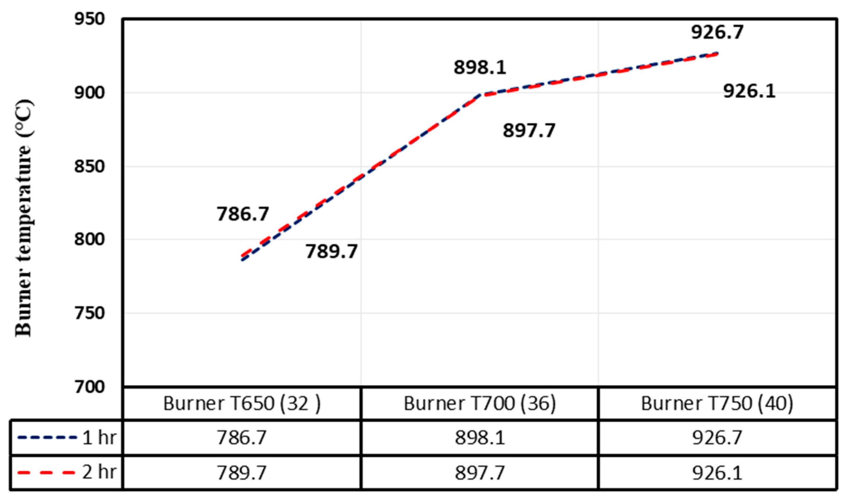
4.1. Effect of Secondary Air on Burner Temperature

In the stove, primary air was supplied to the combustion zone (No. 1) along with the tree branches. Generally, the quantity of air needed for the complete combustion of fuel is determined by controlling the combustion rate and the amount of biomass that can be burned. The primary air is normally mixed with the fuel and then ignited, so this depends on the composition and amount of the air/fuel mixture. Secondary air is primarily supplied above the flames to complete the combustion process and eliminate any byproducts of partial combustion [25,26]. In Figure 5, Figure 6 and Figure 7, it can be seen that increases in burner temperature are related to increases in the combustion process, as the burning of fuels increases heat in the furnace. If the burner temperature is too high or uneven, this can cause a rapid rise in the workpiece temperature, potentially leading to thermal stress and cracks in the material. The temperature in the burner was controlled by the rates at which fuel and air were fed. The results of the gasification process, such as gasifier temperature (GT), burner temperature (BT), and compositions of emission gases, are shown in Table 2. The SA affected BT due to increasing air in the burner, resulting in a high flame temperature and decreased emissions.

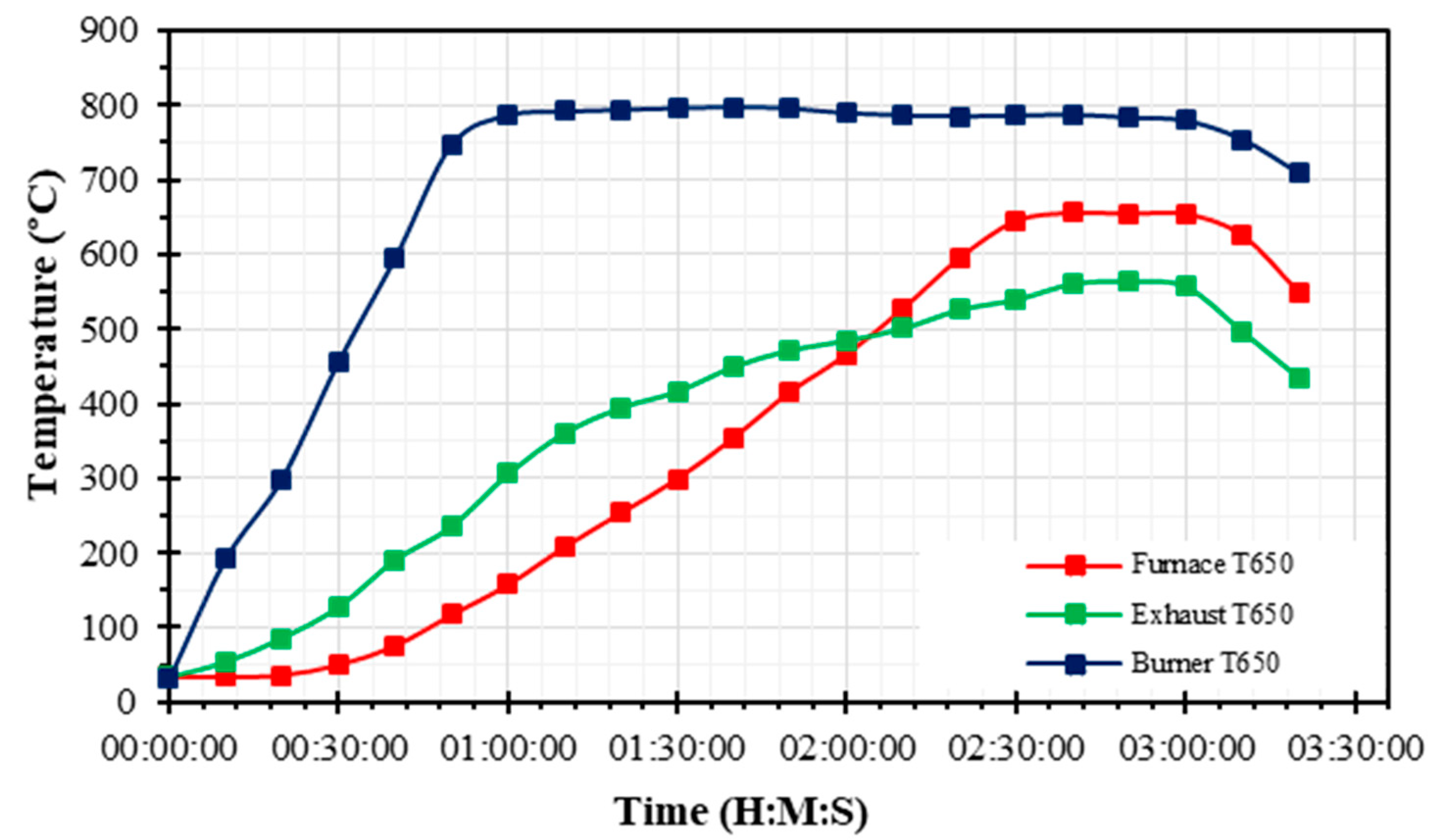
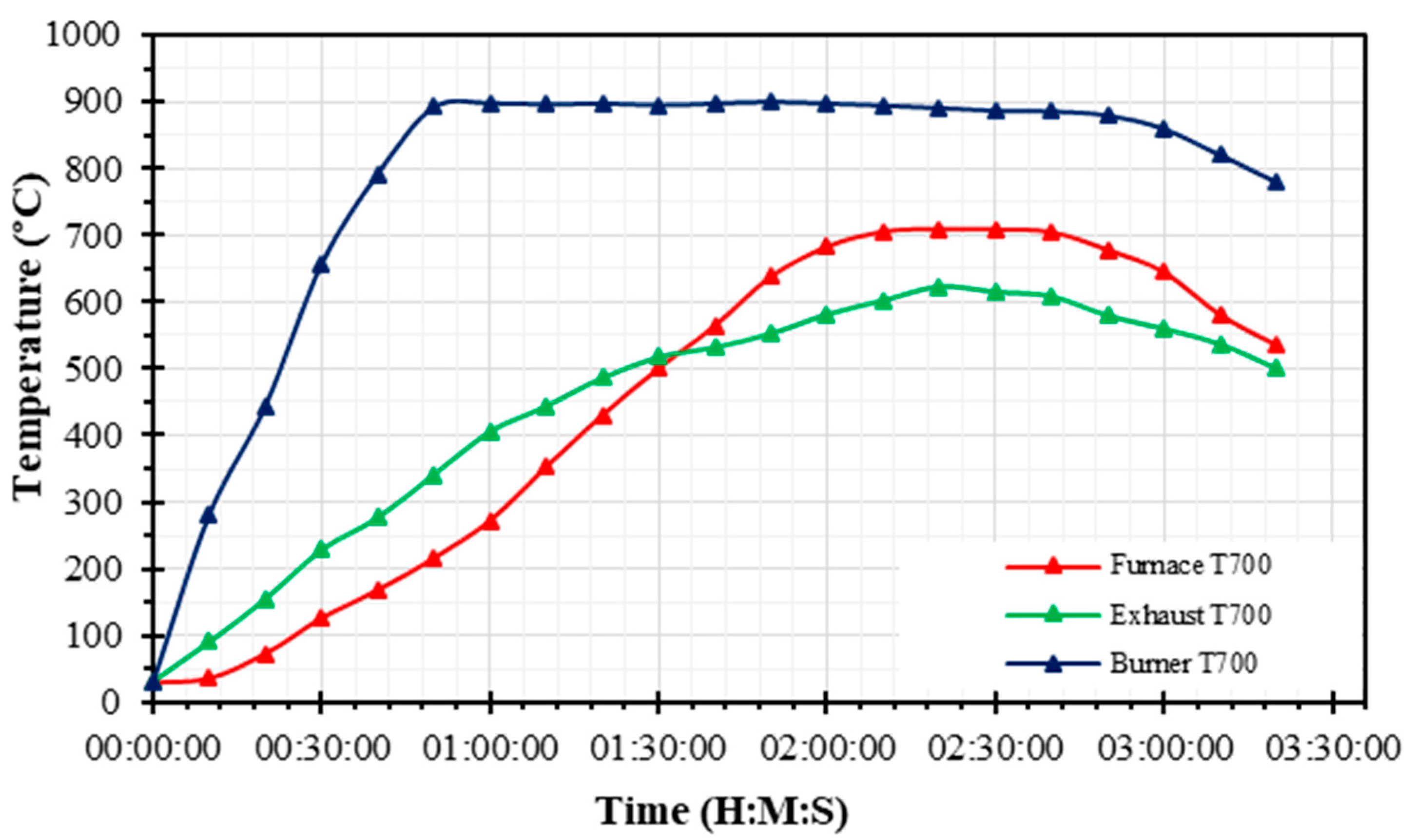
4.2. Annealing Time and Temperature Profile

As shown in Figure 5, the temperature increased from 34.2 °C to 157.4 °C after 1 h and reached 655.9 °C after 2 h and 40 min. This temperature is below the lower critical Ac1, which usually occurs at sub-critical annealing [25,26]. For 2 h, the exhaust temperature was higher than the temperature inside the furnace; after this time, the exhaust temperature dropped while the temperature inside the furnace rose gradually. The total fuel consumption was 39 kg. The total time of the experiment was 3 h 20 min (including 30 min of duration at target temperature and holding on warm temperature until 3 h, as in the two previous experiments (with conditions at 700 °C and 750 °C)). The fuel consumption rate was 14.62 kg/h.
The results of setting the temperature to 700 °C are illustrated in Figure 6. It can be seen that the temperature increased from 29.6 °C to 272.6 °C after 1 h and reached 705.4 °C at 2 h and 10 min (sub-critical annealing) [25,26]. The temperature of the exhaust pipe was higher than the temperature inside the furnace for the first 1 h and 30 min. After that, the exhaust temperature decreased while the temperature inside the furnace gradually increased. The total fuel consumption was 31 kg. The total time of the experiment was 3 h 20 min (including 30 min of duration at target temperature). The fuel consumption rate was 14.31 kg/h.
The results of setting the temperature to 750 °C are illustrated in Figure 7. It can be seen that temperature increased from 28.5 °C to 470.2 °C after 1 h and reached 750.3 °C at 2 h. This temperature is above the lower critical temperature Ac1 but below the upper critical temperature Ac3 (the Ac3 temperature is usually 10–30 °C above the Ac1 temperature [intercritical annealing]) [25,26]. The temperature of the exhaust was higher than the temperature inside the furnace until 1 h and 30 min; after that, the exhaust temperature dropped while the temperature inside the furnace rose gradually. The total fuel consumption was 28 kg. The total experimental time, including a duration at a target temperature of 30 min, was 3 h 20 min. The fuel consumption rate was 14 kg/h.
From our annealing experiment in which different temperatures were set, we found that the amount of fuel and the time required for the process both varied directly with the desired temperature; this is because fuel is required to produce a supply of heat to increase the temperature. Heat transfer by convection also occurs through cold air. In addition, combustion conditions such as the choice of stove model, the type of biomass, the fuel consumption rate, the refeeding of fuel, and the control of air all affect heat production in the gasification process. In addition, soaking time affects the mechanical properties of the wire rod; for example, at the conditions of 750 °C and 700 °C, the duration at the target temperature was 30 min because of the requirement that the duration must not be over 4 h (this experiment was run for 3 h). At the condition of 650 °C, the duration at the target temperature was 30 min, and the warm temperature was held in the furnace until 3 h 20 min. In short, both temperature and annealing time conformed to the mechanical properties of wire rod steel. By controlling all factors, the efficiency of wire annealing was improved [27,28]. The temperature inside the furnace begins to increase from its initial state after the combustion process starts. After 10, 20, and 30 min, the temperature and SA flow rate are recorded at 750 °C with 40 m3/h, 700 °C with 36 m3/h, and 650 °C with 32 m3/h, respectively. The furnace temperature continues to rise steadily, reaching the target temperatures of 750 °C, 700 °C, and 650 °C in 2 h, 2 h and 10 min, and 2 h and 40 min, respectively. The SA flow rate directly influences the increase in flame temperature and indirectly affects the overall furnace temperature increase. The result from this study shows an upward trend in both burner and furnace temperatures. In addition, statistical analysis of the quantitative relationship between temperature fluctuations and changes in mechanical properties and microstructure, influenced by the increased SA flow rate, indicate that a higher SA flow rate leads to a temperature increase in the burner area (Figure 8). This rise in temperature varies significantly with SA, but it is not significant.

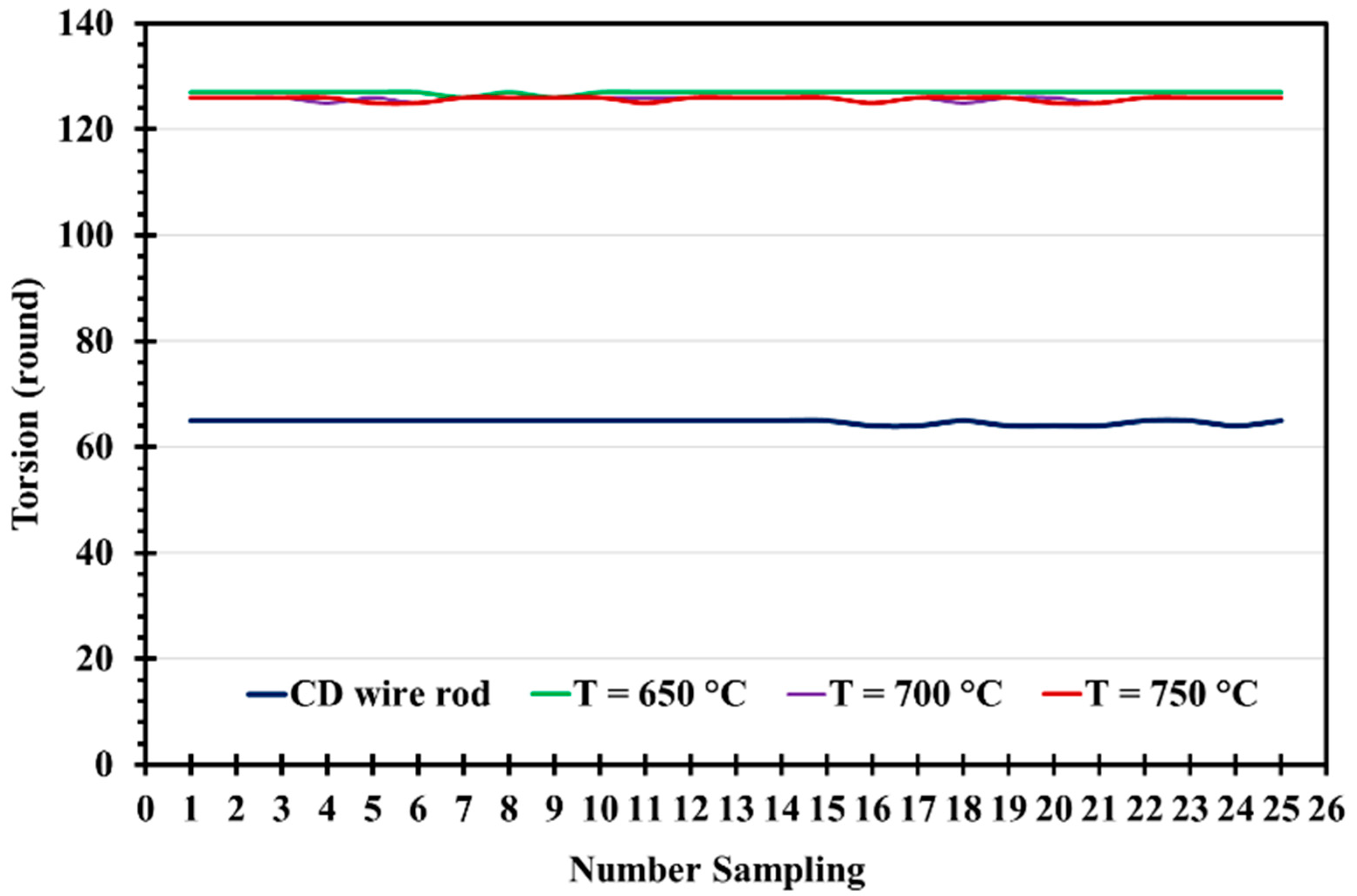
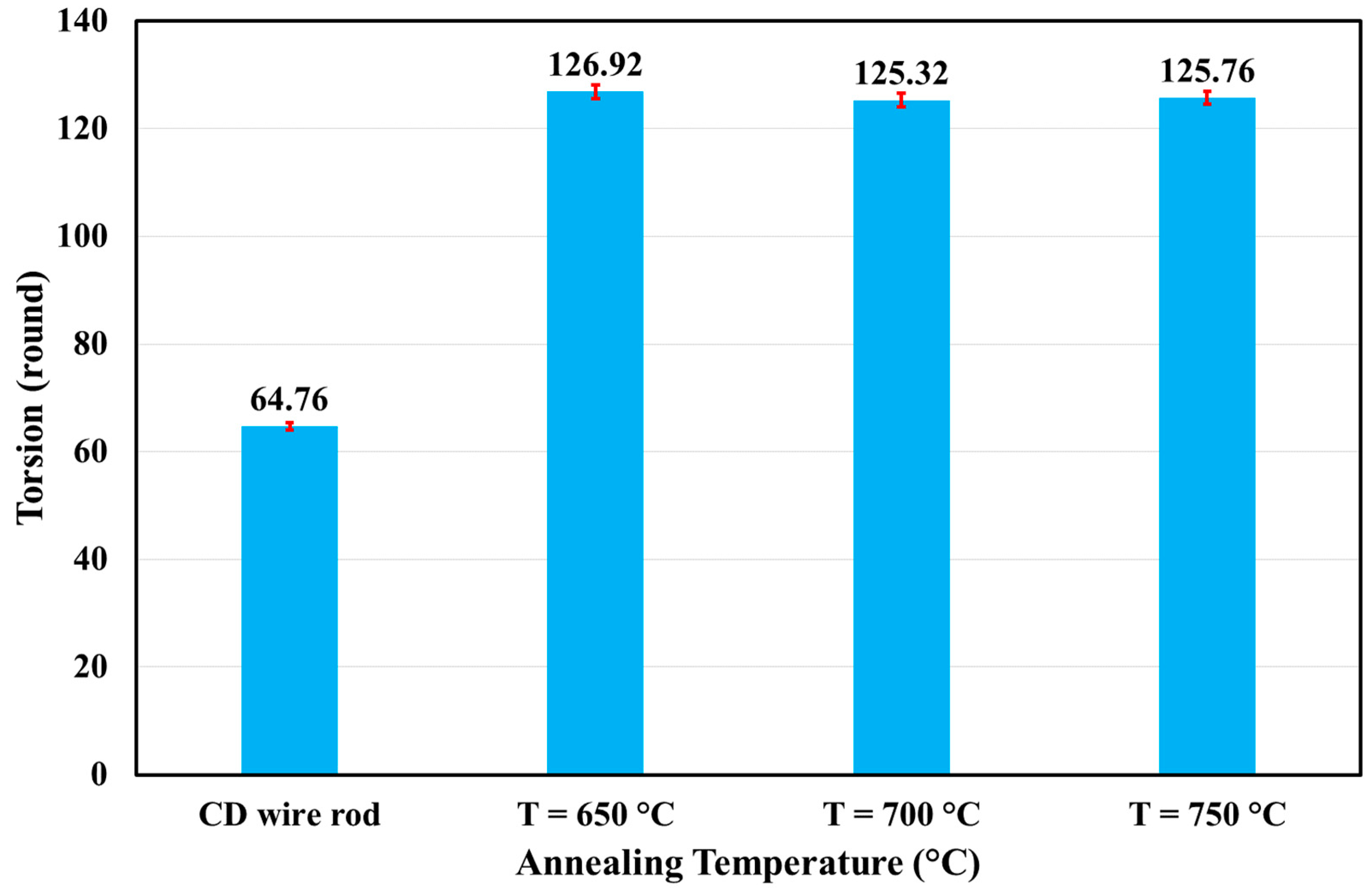
4.3. Tensile Strength and Torsion
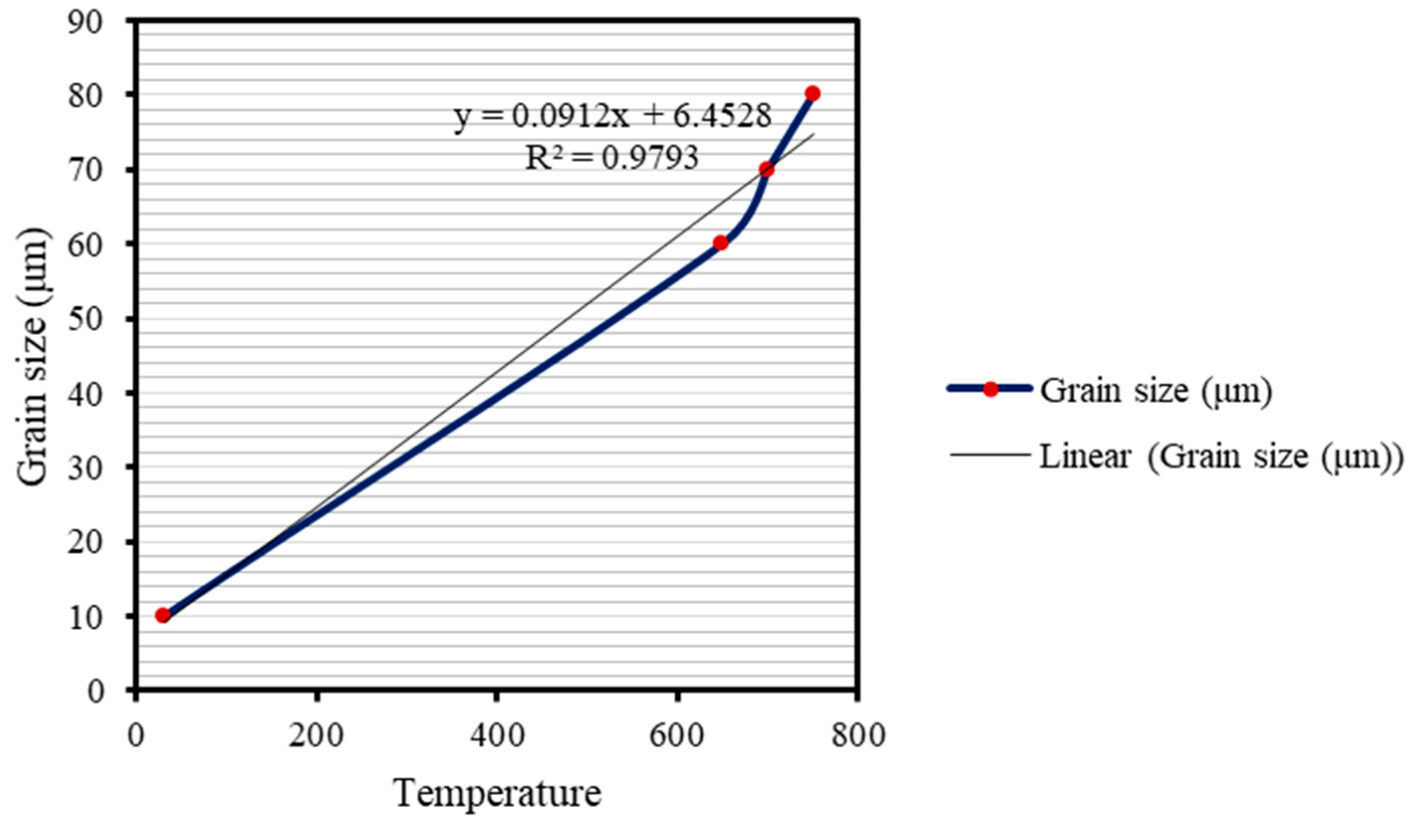
Wire rod steel’s tensile strength and torsion were measured before and after annealing. At 650 °C, 700 °C, and 750 °C, tensile strength was 494.82, 430.87, and 381.33 MPa, respectively. The tensile strength of the cold-drawn wire rod was 994.15 MPa (Figure 9). Tensile strength was, therefore, lowered by the annealing process, depending on temperature. The highest testing temperature (750 °C) resulted in the lowest tensile strength, in agreement with Khoshghadam-Pireyousefan [29], who previously noted that annealing temperature exhibited an inverse relationship with tensile strength. Oliver [4] and Singh [6]. The standard Oliver [4] and Singh [6], which covers only steel binding wires made from low-carbon steel with a diameter of 1.25 mm, requires that the tensile strength of wire rod steel should be greater than or equal to 260 MPa. In the present study, all the steel tested after annealing using a gasifier had a tensile strength of more than 260 MPa. Torsion values obtained from the testing of 25 coil samples are shown in Figure 10 and Figure 11. At temperatures of 650 °C, 700 °C, and 750 °C, average torsion values were 126.92, 125.8, and 125.76, respectively. The torsion value of the cold-drawn wire rod was 64.76.
The results after annealing showed that torsion at all temperatures was more than 100 rounds. Oliver [4] and Singh [6] require torsion to be greater than or equal to 75 rounds. These properties can be used to support the other mechanical properties, such as extension max load, extension break, and % elongation and strain, all of which decreased [30]. In short, the results for tensile strength and torsion obtained in our annealing experiment were within the ranges specified in Oliver [4] and Singh [6].
Statistical testing using ANOVA single factor and the F-test, with α of 0.05, revealed that tensile strength and torsion at annealing temperatures of 650 °C, 700 °C, and 750 °C differ significantly. The p-values obtained were 2.5 × 10⁻⁵ and 6.04 × 10⁻²², respectively, which are less than 0.05, confirming statistical significance.

4.4. Microstructure

The micrograph images in Figure 12 show that the microstructure of the cold-drawn steel included ferrite (white constituent) and pearlite (dark constituent). In the figure, a uniform distribution of grain in cold-drawn wire rod steel can also be seen. The micrograph images show a uniform distribution of grain at different annealing temperatures. The recrystallizing of grain commenced after annealing with a duration at a target temperature of 30 min; the pearlite fraction was slightly increased, and the ferrite grain size also increased. Grain growth increased with increased annealing temperatures, and the grain boundary of annealing steel was larger than that of cold-drawn steel. Correlation analysis between annealing temperature and grain size revealed a correlation coefficient of 0.990 and an R square of 97.93%, indicating a strong direct relationship between grain sizes and increasing annealing temperature (Figure 13). These results agree well with those of Gao et al. [31], Gavariev et al. [32] and Peng [33], all of whom studied the effects of annealing temperature on microstructures.

4.5. Economic Assessment

In this study, we conducted an economic assessment of using a biomass gasifier in an annealing furnace. The assessment focused on the use of a 1 MW cross-draft gasifier, utilizing data from the biomass used in the process (eucalyptus woods). We focused primarily on the savings in fuel costs, excluding considerations such as the investment, operational, and maintenance costs of the gasification system, as well as any potential income from selling carbon credits due to reduced CO2 emissions.

4.6. Biomass Energy Utilization for Heat Production

In this assessment, biomass was considered to be used directly as fuel to replace liquid petroleum gas or natural gas, which are common fuels used extensively in industrial settings to power steam boilers, cement kilns, and, in some industries, annealing furnaces. Several assumptions were also made, as follows:
1. The fuels used for biomass energy production were eucalyptus woods with heating values of 18.72 MJ/kg. The overall price of this biomass was 30 THB/kg (the price of eucalyptus being 3 THB).
2. The heating value of natural gas (CNG) was 52.3 MJ/kg, and its price was 12.74 THB/kg. The heating value and the price of liquid petroleum gas were 45.5 MJ/kg and 18.13THB/kg, respectively.
The detailed calculation is given in Table 3. It is interesting to compare the heating values of CNG and LPG, which are approximately four times higher than that of the biomass-derived synthesis gas. However, when considering price per energy unit, synthesis gas becomes much more attractive. In these calculations, the cost of biomass was compared with that of CNG and LPG. The results show savings in fuel cost of 1191.11 THB and 1804.22 THB, or about 66.5% and 75.04% achieved when biomass replaces CNG and LPG, respectively, the cost of CNG being 1791.11 THB and that of LPG being 2404.22 THB. Furthermore, when comparing the energy consumption efficiency between CNG/LPG and biomass, it is evident that the energy consumption rate for CNG and LPG is 140.59 kg/h and 132.61 kg/h, respectively, while biomass has a consumption rate of 30 kg/h. This results in energy savings of 21.3% and 22.6% when using biomass instead of CNG and LPG, respectively.
The comparative energy efficiency data for biomass and fossil fuels show that using biomass energy not only reduces energy costs but also enhances energy efficiency in industrial facilities, particularly in the annealing process of wire rod steel.

4.7. Environmental Assessment

In Table 2, we may state that acceptable pollution levels in industrial operations must not exceed the following standard limits: NOx 200 ppm and CO 690 ppm. Based on the measured values, the average NOx across the three temperatures was 185 ppm, and the average CO across the three temperatures was 225 ppm. These results indicate that pollution levels were within acceptable limits.

5. Conclusions

In this study, we annealed wire rod steel using a cross-draft gasifier at different temperatures, specifically, 650 °C, 700 °C, and 750 °C. The cold-drawn wire rod was also annealed. After annealing and cooling at a natural temperature for 24 h, we used sample pieces of wire rod steel in different situations to test their mechanical properties. In addition, we analyzed and compared the experimental results of annealing wire rod steel using a cross-draft gasifier at different temperatures with the results of annealing using CNG. From our results, the following conclusions were drawn.
Maximum values for tensile strength and torsion were found to be 494.82 MPa and 127 rounds, respectively, showing that the mechanical properties of this wire rod steel are suitable for use in industrial work.
The minimum temperature for annealing wire rod steel was 650 °C. At this temperature, the processing time was 2 h 40 min, and the mechanical properties of the steel are suitable for use in industrial work.
The use of CNG for annealing wire rod steel is associated with high cost; in contrast, fuel from biomass is very cheap and easy to store for use in annealing wire rod steel.
The environmental assessment showed that the use of a biomass gasifier for an annealing furnace is within the acceptable limits of pollution levels.
Increases in annealing temperatures and soaking times affect microstructure so that ferrite increases above the grain boundary.
From these conclusions, we may state that fuel from biomass can be used to produce heat energy for annealing wire rod steel; however, the effectiveness of the annealing process is affected by such factors as variations in the fuel feeding rate, fluctuations in temperature, the type of biomass used, and the design of the furnace.

Author Contributions

P.C.: conceptualization, methodology, data curation, investigation, writing—original draft, writing—review and editing, and visualization; P.C.: methodology, investigation, and data curation; S.K.: methodology, investigation, and data curation; P.C.: methodology and investigation; S.K.: supervision, project administration, and funding acquisition; S.W.: supervision, project administration, and funding acquisition. All authors have read and agreed to the published version of the manuscript.

Funding

This research received no external funding.

Data Availability Statement

The original contributions presented in this study are included in the article. Further inquiries can be directed to the corresponding author.

Acknowledgments

The authors would like to thank the Graduate School of Srinakharinwirot University (GS) for supporting the following projects. They also extend their thanks to the Italian-Thai Development Corporation Limited (ITD) and the Biofuel and Bioenergy Technology Research and Development Laboratory (BBT R&D), Department of Mechanical Engineering, Faculty of Engineering, Srinakharinwirot University, for supplying the materials necessary for studying, experimenting, and testing the product as wire rod steel.

Conflicts of Interest

The authors declare no conflicts of interest.

References

  1. Sánchez de León, J.A. A mathematical model for the prediction of mechanical properties on ASTM A510/A853 cold-drawn hypoeutectoid steel wire after batch annealing. Math. Mech. Solids 2024, 29, 833–853. [Google Scholar] [CrossRef]
  2. Zykova, A.; Panfilov, A.; Nikolaeva, A.; Gurianov, D.; Chumaevskii, A.; Kolubaev, E.; Tarasov, S.Y. Effect of Heat Treatment on the Evolution of Structural and Phase State in Wire Electron Beam Additively Manufactured Al–12Si Alloy. Russ. Phys. J. 2024, 67, 1172–1179. [Google Scholar] [CrossRef]
  3. Voroshilov, D.; Sidelnikov, S.; Darmazhapov, D.; Pokshivanov, S.; Bespalov, V.; Durnopyanov, A.; Berngardt, V.; Lezhnev, S.; Motkov, M.; Voroshilova, M. Electrical wire production from al-ce-la alloy rods after electromagnetic mold and combined rolling-extrusion. J. Chem. Technol. Metall. 2025, 60, 327–336. [Google Scholar] [CrossRef]
  4. Oliver Reynoso, A.; Vázquez-Gómez, O.; Reyes-Calderón, F.; Vergara-Hernández, H.J.; Herrejón-Escutia, M.; Dávila-Pérez, M.I.; López-Martínez, E. Kinetics of austenite formation during continuous heating in as-cast and as-annealed conditions in a low carbon steel. Mater. Res. Express 2025, 12, 026502. [Google Scholar] [CrossRef]
  5. Feng, C.; Pan, G.; Yang, J. Identification of key renewable energy sectors for global energy transition based on industrial linkage analysis. Renew. Energy 2025, 245, 122651. [Google Scholar] [CrossRef]
  6. Singh, V.K.; Rana, R.; Singh, S.B.; Kundu, A. Effects of Temperatures of Rolling and Annealing on Microstructures and Tensile Properties of Low Carbon Ferritic Low Density Steels. ISIJ Int. 2023, 63, 930–940. [Google Scholar] [CrossRef]
  7. Godknows, D.; Chuanbao, L.; Guangchao, D.; Abdoulaye, B.; Kouame; Tinashe, T.; Atta, U.; Muhammad, Z.; Songgeng, L.; Liang, Z. Techno-economic analysis of small-scale ammonia production via sorption-enhanced gasification of biomass. Chem. Eng. J. 2024, 490, 151666. [Google Scholar] [CrossRef]
  8. Zhenting, Z.; Zefeng, G.; Yuna, M.; Mingxun, Z.; Yuqing, W.; Zenghui, H.; Fangzhou, L.; Huiyan, Z. Hydrogen-rich syngas production and insight into morphology-kinetics correlation for furfural residue steam gasification in a bubbling fluidized bed. Chem. Eng. J. 2023, 477, 147151. [Google Scholar] [CrossRef]
  9. Arruda Ferraz de Campos, V.; Carmo-Calado, L.; Mota-Panizio, R.; Matos, V.; Silva, V.B.; Brito, P.S.; Eusébio, D.F.L.; Tuna, C.E.; Silveira, J.L. A Waste-to-Energy Technical Approach: Syngas–Biodiesel Blend for Power Generation. Energies 2023, 16, 7384. [Google Scholar] [CrossRef]
  10. Perreault, P.; Boruntea, C.-R.; Dhawan Yadav, H.; Portela Soliño, I.; Kummamuru, N.B. Combined Methane Pyrolysis and Solid Carbon Gasification for Electrified CO2-Free Hydrogen and Syngas Production. Energies 2023, 16, 7316. [Google Scholar] [CrossRef]
  11. Diboma, B.S.; Atiotsia, V.H.; Che, L.C.; Essomba, P.B.; Bot, B.V.; Tamba, J.G. Gasification of charcoal derived from tropical wood residues in an updraft fixed bed reactor. Bioresour. Technol. Rep. 2023, 21, 101308. [Google Scholar] [CrossRef]
  12. Rahman, M.M.; Henriksen, U.B.; Ciolkosz, D. Startup process, safety and risk assessment of biomass gasification for off-grid rural electrification. Sci. Rep. 2023, 13, 21395. [Google Scholar] [CrossRef]
  13. Choukri, O.; Mohsine, E.; Taibi, S. Industrial Recycling of Scrap Copper Cables and Wires: Combining Cold and Hot Treatments for Maximum Recovery and Minimal Emissions. Arch. Foundry Eng. 2024, 2024, 153–162. [Google Scholar]
  14. Kieush, L.; Rieger, J.; Attrotto, R.; Sorino, A.; van der Stricht, W.; Oterdoom, H.; Heikkinen, E.P.; Dall’Osto, G.; Mapelli, C.; Mombelli, D. Roadmap for recycling practices and resource utilization in the iron and steelmaking industry: A case studies. Matériaux Tech. 2024, 112, 503. [Google Scholar]
  15. Unsomsri, N.; Kaewluan, S.; Tawkaew, S.; Wiriyasart, S. Characterization of palm pyrolysis oil produced from fresh palm fruit bunches with a modified downdraft biomass gasifier and burner as heat source. J. Anal. Appl. Pyrolysis 2025, 186, 106917. [Google Scholar] [CrossRef]
  16. Ayyadurai, S.; Muthukathan Rajendran, S.; Vijayakumar, P.; Jester Lih Jie, L.; See Hoon, L. Green circular economy of co-gasification with municipal solid waste and wood waste in a novel downdraft gasifier with rotating grate. Chem. Eng. J. 2024, 479, 147987. [Google Scholar] [CrossRef]
  17. Qiu, L.; Li, C.; Zhang, S.; Wang, S.; Li, B.; Cui, Z.; Tang, Y.; Hu, X. Distinct property of biochar from pyrolysis of poplar wood, bark, and leaves of the same origin. Ind. Crops Prod. 2023, 202, 117001. [Google Scholar] [CrossRef]
  18. Shao, S.; Ma, L.; Li, X.; Zhang, H.; Xiao, R. Preparation of activated carbon with heavy fraction of bio-oil from rape straw pyrolysis as carbon source and its performance in the aldol condensation for aviation fuel as carrier. Ind. Crops Prod. 2023, 192, 115912. [Google Scholar] [CrossRef]
  19. Pan, S.; Zabed, H.M.; Wei, Y.; Qi, X. Technoeconomic and environmental perspectives of biofuel production from sugarcane bagasse: Current status, challenges and future outlook. Ind. Crops Prod. 2022, 188, 115684. [Google Scholar] [CrossRef]
  20. Shao, S.; Sun, T.; Li, X.; Wang, Y.; Ma, L.; Liu, Z.; Wu, S. Preparation of heavy bio-oil-based porous carbon by pyrolysis gas activation and its performance in the aldol condensation for aviation fuel as catalyst carrier. Ind. Crops Prod. 2024, 218, 118963. [Google Scholar] [CrossRef]
  21. Premanand, G.; Jana, D.; Das, S.K. Oxidation of Ni (H2O) 6@ MoO3 to Ni2O3/MoO3 Composites by Aerial Annealing: Electrocatalytic Hydrogen Evolution. Chem.–Asian J. 2025, 20, e202401172. [Google Scholar] [PubMed]
  22. Weiming, H.; Ruichi, Z.; Apostolos, G.; Chuanhao, L.; Chao, H. Sequential hydrothermal carbonization and CO2 gasification of sewage sludge for improved syngas production with mitigated emissions of NOx precursors. Chem. Eng. J. 2023, 454, 140239. [Google Scholar] [CrossRef]
  23. Andini, A.; Aminuddin, A.; Helios, M.; Sajjakulnukit, B.; Nasir, S. Eucalyptus gasification using a multi-stage air gasifier: An experimental study. In BIO Web of Conferences; EDP Sciences: Ulis, France, 2025; Volume 159, p. 03001. [Google Scholar]
  24. Luo, Y.; Li, H.; Ke, H.; Zhou, P.; Corbi, O.; Corbi, I. Research on the basic mechanical properties of eucalyptus wood scrimber. Constr. Build. Mater. 2025, 467, 140366. [Google Scholar] [CrossRef]
  25. Unsomsri, N.; Manchit, P.; Tabrak, P.; Wiriyasart, S.; Kaewluan, S. Effect of Oxygen-Enriched Air on Flame Temperature and Emission Characteristics During Hot Producer Gas Combustion in a Modified Cross-draft Gasifier-Burner. Combust. Sci. Technol. 2024, 1–15. [Google Scholar] [CrossRef]
  26. Kaewluan, S.; Wiriyasart, S. Waste heat recovery from household biomass gasifier stoves (HBGSs) for thermoelectric generators: Effect of the primary air valve angle. Heat Transf. 2023, 53, 1117–1135. [Google Scholar] [CrossRef]
  27. Yang, W.S.; Kim, J.H.; Kim, M.J.; Yang, S.Y.; Lee, A.-Y.; Esmaeilpoor, H.; Kim, J.H.; Lee, K.S. Evolution of magnetocaloric anisotropy in gadolinium wires induced by cold drawing. J. Alloys Compd. 2025, 1014, 178657. [Google Scholar] [CrossRef]
  28. Chen, Y.; Hao, Z.; Li, Y.; Liu, C.; Liu, Y.; Luo, Z.; Ao, S. Enhancing Mechanical Properties: Exploring the Effect of Annealing Temperature on Wire Arc Additively Manufactured High-Strength Steel. Materials 2023, 16, 6969. [Google Scholar] [CrossRef]
  29. Khoshghadam-Pireyousefan, M.; Javidani, M.; Maltais, A.; Lévesque, J.; Chen, X.-G. Effect of Post-annealing on Mechanical Properties and Microstructural Evolution of Ultrafine Grained Hypoeutectic Al-Si Conductor Wires. In TMS Annual Meeting & Exhibition; Springer: Berlin/Heidelberg, Germany, 2025; pp. 171–178. [Google Scholar]
  30. Ma, G.; Sheng, J.; Gao, Y.; Tuo, L.; Li, Y.; La, P. Effect of Annealing Temperature on Microstructure and Mechanical Properties of 00Cr21CuTi Stainless Steel Cold-Rolled Sheets. Metals 2024, 14, 1367. [Google Scholar] [CrossRef]
  31. Gao, X.; Gao, G.; Li, Z.; Li, X.; Yan, L.; Zhang, Y.; Xiong, B. The effect of different preparation methods on the microstructure and mechanical properties of Al-Zn-Mg-Cu alloy wire. J. Phys. Conf. Ser. 2025, 2954, 012094. [Google Scholar]
  32. Gavariev, R.; Gavarieva, K.; Kirsanov, A. To the Question of Manufacturing Wire for Cold Bulk Metal Forming: A Review. In International Conference on Industrial Engineering; Springer: Berlin/Heidelberg, Germany, 2024; pp. 829–839. [Google Scholar]
  33. Peng, J.; Zhang, T.; Xu, L.; Chen, G.; Hu, D.; Zhu, Z.; Ma, J.; Sindo, K. Effect of C-Mn-Cu on microstructure and properties of wire arc additive manufacturing of high-manganese steels. Mater. Sci. Technol. 2024, 40, 1202–1218. [Google Scholar]
Figure 1. Equipment for annealing wire rod steel. (1) Cross-draft gasifier. (2) Air pump. (3) Rotameter. (4) Wire rod steel annealing furnace. (5) Exhaust pipe. (6) Rotary blower. T1—temperature at throat, T2—temperature at furnace; T3—temperature at exhaust.
Energies 18 01912 g001
Figure 2. Structure of equipment used for annealing wire rod steel.
Energies 18 01912 g002
Figure 3. Section view of equipment for annealing wire rod steel and position of wire rod.
Energies 18 01912 g003
Figure 4. Preparing chopped firewood (a). Weighting (b). Feeding (c). Burning and recording data (d).
Energies 18 01912 g004
Figure 5. The annealing time process of wire rod steel and the rate of internal furnace, exhaust, and burner temperature increase at 650 °C.
Energies 18 01912 g005
Figure 6. The annealing time process of wire rod steel and the rate of internal furnace, exhaust, and burner temperature increase at 700 °C.
Energies 18 01912 g006
Figure 7. The annealing time process of wire rod steel and the rate of internal furnace, exhaust, and burner temperature increase at 750 °C.
Energies 18 01912 g007
Figure 8. The quantitative relationship between burner temperature with SA flow rate.
Energies 18 01912 g008
Figure 9. Tensile strength values for cold-drawn write rod and wire rod steel annealed at rate temperature increases of 650 °C, 700 °C, and 750 °C; values are averages of three samples.
Energies 18 01912 g009
Figure 10. Torsion values for cold-drawn wire rod and wire rod steel annealed at rate temperature increases of 650 °C, 700 °C, and 750 °C.
Energies 18 01912 g010
Figure 11. Average torsion values for cold-drawn wire rod and wire rod steel annealed at rate temperature increases of 650 °C, 700 °C, and 750 °C.
Energies 18 01912 g011
Figure 12. Microstructures of cold-drawn wire rod steel after annealing at temperatures of 650, 700, and 750 °C with grain sizes of 10, 60, 70, and 80 μm, respectively. (a,c,e,g) show the cross-section, while (b,d,f,h) show the side section.
Energies 18 01912 g012
Figure 13. The quantitative relationship between annealing temperature and SA rise significantly affects microstructural changes.
Energies 18 01912 g013
Table 1. Accuracy of measurements.
Instrument Accuracy (%)
Thermocouple type K (°C)0.1
Universal testing machines0.3–1
Data logger (°C)0.01
Rotameter (m3/h)1.6–5
Table 2. Effect of secondary air.
AT (°C)PA (m3/h)SA (m3/h)GT (°C)BT (°C)O2 (%Vol)CO (ppm)NOX (ppm)
6502032800.78003.9219180
70036801.49004.05226186
75040802.69504.15229189
Table 3. Economic assessment of the utilization of biomass energy produced from eucalyptus wood to replace CNG and LPG in the annealing process.
Items Units
Heating gas annealing furnace
Thermal energy628.2kWh
CNG
CNG heating value52.3MJ/kg
CNG price12.74THB/kg
CNG consumption rate *140.59kg/h
CNG cost1791.11THB
LPG
LPG heating value45.5MJ/kg
LPG price18.13THB/kg
LPG consumption rate *132.61kg/h
LPG cost2404.22THB
Gasifier annealing furnace
Gasifier thermal capacity1MW
Biomass energy input316.83kWh
Eucalyptus wood heating value18.72MJ/kg
Eucalyptus wood price3THB/kg
Biomass consumption rate *30kg/h
Biomass cost600THB
Fuel cost savings from CNG1191.11THB
Fuel cost savings from LPG1804.22THB
* Time process: 4 h.
Disclaimer/Publisher’s Note: The statements, opinions and data contained in all publications are solely those of the individual author(s) and contributor(s) and not of MDPI and/or the editor(s). MDPI and/or the editor(s) disclaim responsibility for any injury to people or property resulting from any ideas, methods, instructions or products referred to in the content.

