Article

Optimum Design of a Photovoltaic Inverter System Based on Ga, Pso and Gwo Algorithms with a Mppt Sliding Mode Control

by
Alberto Coronado-Mendoza
1,*,
Mónica Camas-Náfate
1,
Jesús Sergio Artal-Sevil
2 and
José Antonio Domínguez-Navarro
2
1
Studies on Water and Energy Department, University of Guadalajara, Tonala Campus, Nuevo Periferico Av. 555, Jalisco 45425, Mexico
2
Department of Electrical Engineering EINA, University of Zaragoza, María de Luna 3, 50018 Zaragoza, Spain
*
Author to whom correspondence should be addressed.
Energies 2025, 18(8), 1911; https://doi.org/10.3390/en18081911
Submission received: 27 February 2025 / Revised: 3 April 2025 / Accepted: 4 April 2025 / Published: 9 April 2025
(This article belongs to the Section A2: Solar Energy and Photovoltaic Systems)

Abstract

The deployment of photovoltaic single-phase inverters has been rapidly increasing worldwide. However, the performance of these systems is highly influenced by atmospheric conditions and load variations, necessitating the development of performance indices to enhance their efficiency and energy quality. In this study, four performance indices are proposed to evaluate the efficiency and energy quality of photovoltaic systems quantitatively. The entire process is analyzed, encompassing solar energy capture, DC-DC and DC-AC conversion, and filtering, to deliver maximum energy and quality to the load. Furthermore, eight system parameters are optimized using advanced techniques such as genetic algorithms, particle swarm optimization, and gray wolf optimization. These optimizations enhance the global performance of two critical stages: (1) the maximum power point tracking algorithm based on sliding mode control, which minimizes switching losses in the boost stage, and (2) the effective transfer of captured solar power to the load by optimizing the gains of a PI controller. The PI controller computes the switching triggers for the inverter stage, significantly improving the total harmonic distortion of voltage and current waveforms. Simulation results validate the proposed approach, demonstrating a marked improvement in overall system efficiency (95.8%) when compared to the incremental conductance method (−11.8%) and a baseline sliding mode control configuration (−1.14%).

1. Introduction

The global adoption of residential photovoltaic (PV) systems has seen exponential growth, with single-phase systems representing the majority of installations. These systems operate under dynamic environmental conditions, such as fluctuations in solar irradiation and temperature, as well as parametric and load variations, which significantly impact their operational efficiency [1]. To maximize power extraction, various Maximum Power Point Tracking (MPPT) algorithms have been developed, including traditional methods like Perturb and Observe (P&O), Incremental Conductance (InCond), and advanced techniques such as Fuzzy Logic Control (FLC), Neural Networks (NNs), and Sliding Mode Control (SMC) [2].
Among these, SMC has gained popularity due to its robustness and rapid convergence under varying conditions [3]. Recent advancements in SMC include hybrid approaches such as Fuzzy Type-2 controllers, adaptive SMC with variable step sizes, and integration with other optimization techniques like Genetic Algorithms (GAs) [4,5,6]. Additionally, hybrid methods combining SMC with Proportional–Integral (PI) controllers or sliding mode integral techniques have been explored to enhance system performance [7,8,9]. These methods aim to address challenges such as chattering phenomena, steady-state errors, and transient response times, which are essential for maintaining PV system efficiency [10].
PV systems typically operate in two configurations: grid-connected and isolated. In both cases, the primary objective is to transfer maximum available power to the load with high energy quality and efficiency [11]. The system architecture generally consists of multiple stages: (1) a PV array that captures solar energy and converts it into electrical power, (2) a DC-DC converter stage where MPPT algorithms are implemented, (3) an inverter stage that converts DC power to AC for load consumption, and (4) a filtering stage to ensure high-quality power delivery [12]. Each stage introduces unique challenges, such as switching losses, harmonic distortions, and dynamic load variations, which require the implementation of robust control strategies. Table 1 provides an overview of key performance indexes reviewed in the literature.
To evaluate the performance of these control algorithms, several metrics are commonly used, including Total Harmonic Distortion (THD), tracking efficiency, steady-state error, and transient response speed [16]. For instance, studies have examined the impact of partial shading [13], irradiation changes [19], and temperature variations [14] on system performance. However, many existing approaches focus on optimizing individual stages rather than the system as a whole, resulting in suboptimal overall performance [15]. Moreover, while traditional MPPT algorithms such as P&O and InCond are widely used, they often struggle with rapid environmental changes and fail to achieve global optimization [20].
Despite the advancements in SMC and hybrid control techniques, several gaps remain in the literature. First, many studies focus on single-stage optimization, neglecting the interplay between different system stages [21]. Second, while performance metrics like THD and tracking efficiency are commonly used, there is a lack of comprehensive indicators that evaluate the system holistically [17]. Third, the integration of advanced optimization techniques, such as GAs, with SMC for multi-objective optimization remains underexplored [18]. These gaps highlight the need for a more integrated approach to PV system control, one that balances power extraction, transfer efficiency, and energy quality across all stages [26]. In recent years, research on MPPT algorithms under partial shading conditions has gained traction, with approaches such as Musical Chairs Algorithms (MCAs) [27] and Nest Particle Swarm Optimization (NEST PSO) [28] demonstrating superior performance in these scenarios.
In this work, we address these gaps by proposing a novel control strategy for a 1.2 kW two-stage single-phase PV system. The system comprises a boost converter with switching losses and an inverter stage with an LC filter. We design and optimize a sliding mode control algorithm to achieve balanced MPPT performance, integrating it with a PI controller for efficient power transfer to the load. Additionally, we employ Genetic Algorithms to optimize eight system parameters, including LC filter values, integration step size, and PI gains. A unique objective function is defined, incorporating four performance indexes: power extraction error, power transfer error, and THD of output current and voltage. This holistic approach ensures optimal system performance under varying irradiation conditions, outperforming traditional methods like InCond and non-optimized SMC, as demonstrated through MATLAB/Simulink simulations.
The contributions of this study are threefold: (1) a comprehensive state-of-the-art review of MPPT techniques and their limitations, (2) a novel integrated control strategy that optimizes both power extraction and transfer efficiency, and (3) a multi-objective optimization framework that balances competing performance metrics. By addressing these challenges, this work advances the field of PV system control and offers a robust solution for enhancing the efficiency and reliability of residential PV installations.

2. Materials and Methods

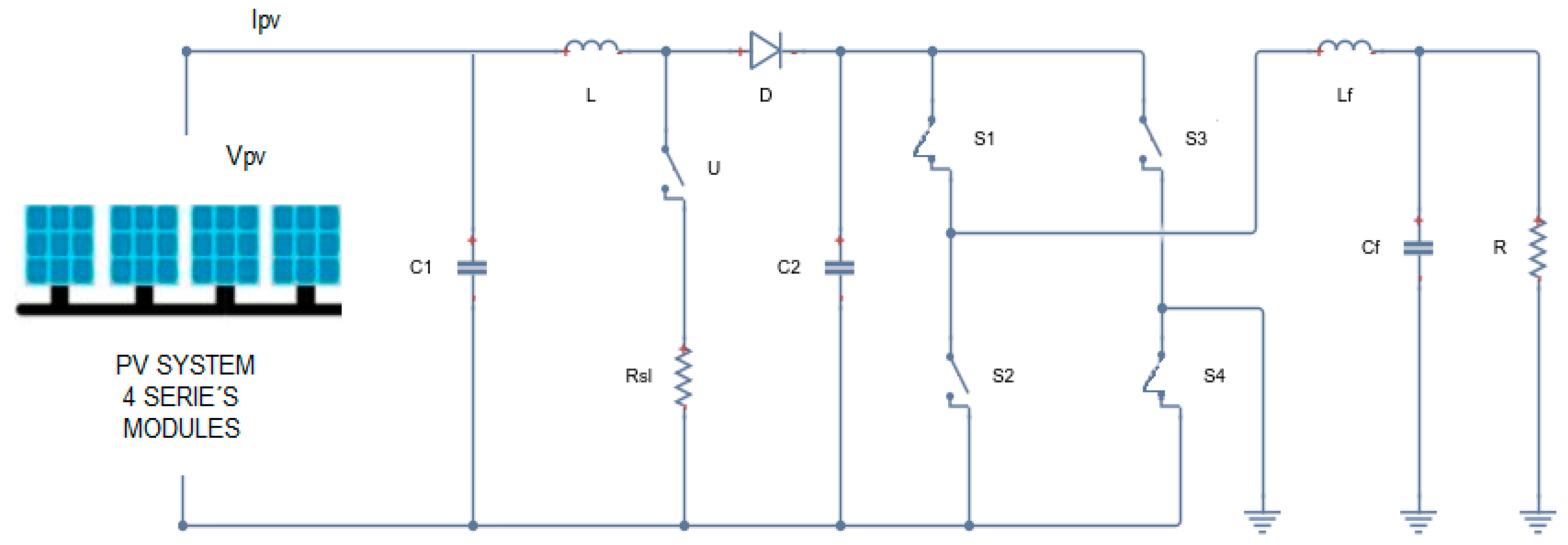
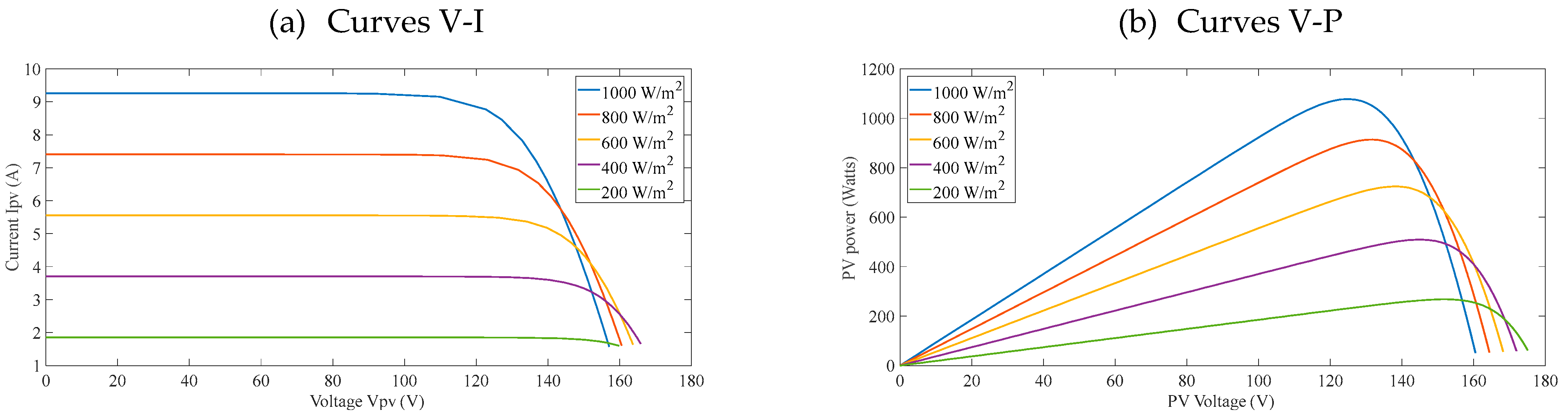
2.1. System Description

The configuration of the system is shown in Figure 1, based on [22]. It is composed of a PV array of four modules and a two-stage single-phase inverter. The first stage is a DC-DC boost converter, responsible for the MPPT, and the second stage converts the DC into AC voltage, which is applied to the load through an LC filter.
Where C 1 ,   C 2 , and C f are capacitances; L and L f are inductances; R s l is resistance that is introduced to reflect the commutation power losses; R is the load; u = 1 ,   0 is the discrete signal control of the boost stage; and S 1 4 = 1 ,   0 are the switches of the inverter stage. The mathematical model of the system is expressed by Equations (1)–(5):
d v c 1 d t = 1 C 1 i p v i L
d i L d t = 1 L v C 1 1 u v c 2 u R s l i L
d v c 2 d t = 1 C 2 1 u i L + a i L f
d i L f d t = 1 L f b v c 2 V C f
d v C f d t = 1 C f i L f v C f / R
where i p v is the current provided by the PV array, i L and i L f are the inductor current of the boost and filtering stage, respectively, V C 2 is the DC bus voltage, and V C f is the filtered voltage delivered to the load R . Parameters a and b define the sign of the filtered current and the polarity of the DC bus voltage, and they are defined as follows: a = ( 1 ) 2 S 1 , b = 1 / 2 ( 1 ) 2 S 1 + ( 1 ) 2 S 4 ; u and s 1 4 are control signals.
The characteristic function that describes the behavior of the PV module is expressed by Equation (6) [29]:
i p v = i s c 1 e x p ^ ( ( v p v v o c + R s i p v ) / V t )
where ipv is the PV ouput current, isc is the short circuit current, vpv is the PV output voltage, voc is the open circuit voltage, Rs is the series resistance, and Vt is the thermal stress.
Characteristic curves of this model are presented in Figure 2. System performance analysis is critical for optimizing energy extraction and ensuring efficient operation. The figure depicts a power–voltage (P-V) curve, illustrating how power output changes with PV voltage across different irradiation levels (200 W/m2 to 1000 W/m2), with distinct peaks indicating the maximum power point (MPP) for each condition. These highlight the importance of Maximum Power Point Tracking (MPPT) algorithms to optimize energy extraction under dynamic conditions.
To evaluate the performance of the MPPT algorithm, we compute the maximum power captured by the PV array, and it will be explained in Section 4.

2.2. Control Algorithms

This section presents the two controls that are used in the two stages of the system: the first is a sliding mode control designed for the boost converter, and the second is a classic PI control for the inverter stage.

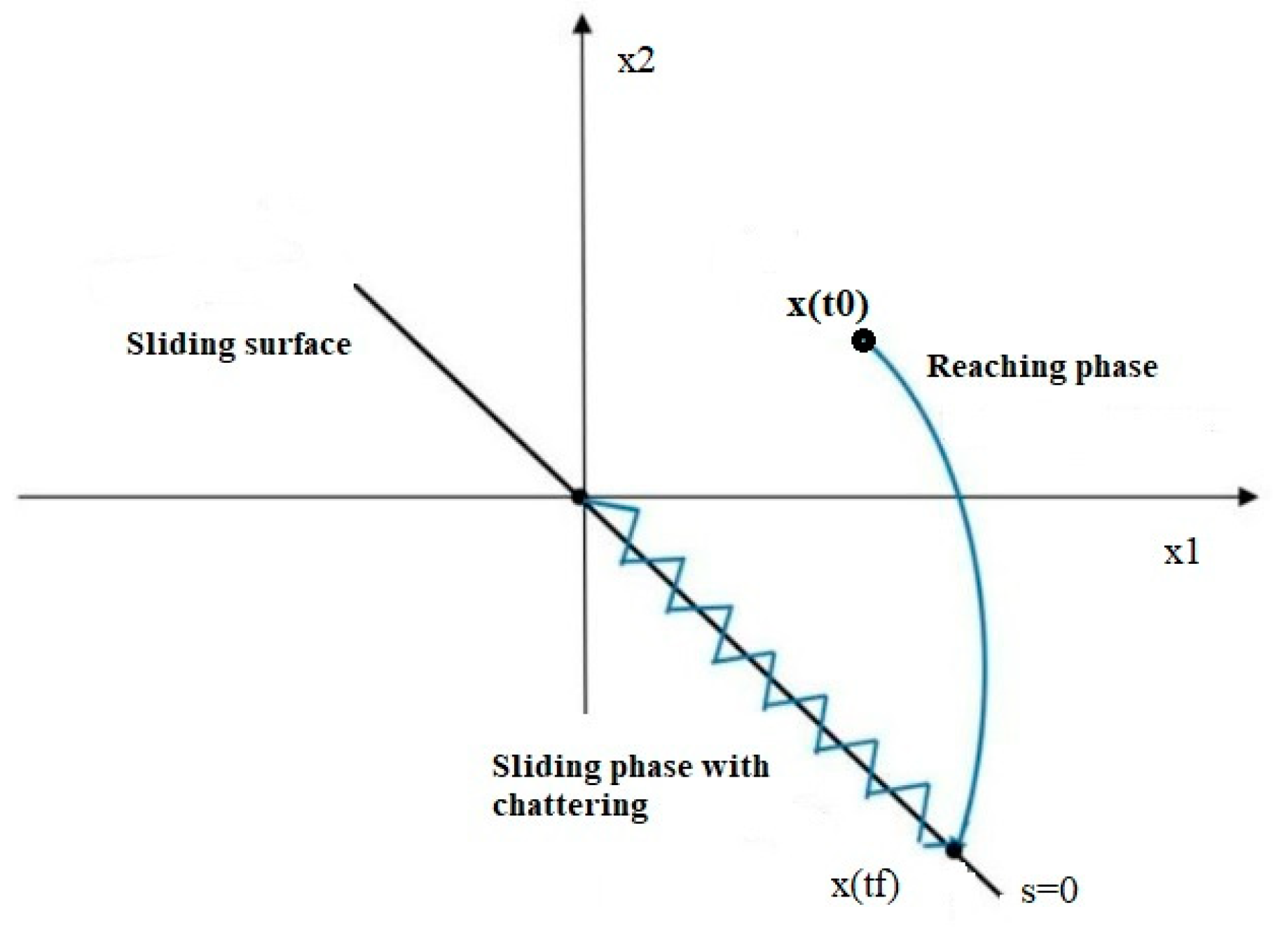
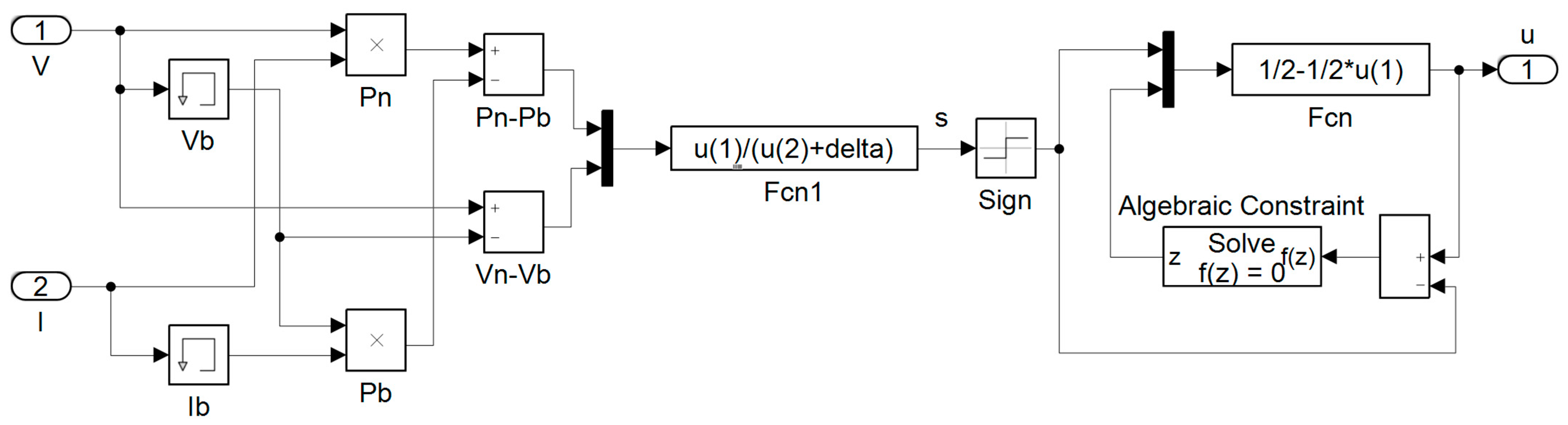
2.2.1. MPPT with SMC

The main idea of SMC is to force the system’s state to reach the sliding surface and stay there. It consists of two phases: the reaching phase and the sliding one, as it is represented in Figure 3. The main advantage of this type of discontinuous control is its robustness to uncertainties and disturbances. An undesirable performance is chattering phenomena.
Let us define the sliding mode surface as
s = d P p v / ( d V + δ )
where d P p v = P p v t P p v t T s is the incremental power of the PV array at a time interval t T s ; T s is the fixed-step size; P p v = v p v i p v is the instantaneous photovoltaic power defined as the product of voltage and current; d V = V p v t V p v t T s is the incremental voltage that defines the new operation point of the PV array; and δ > 0 .
Then, the control signal u is defined by Equation (8).
u = 1 / 2 1 / 2 s i g n ( s )
Figure 4 shows the implementation of SMC in Simulink. The use of a memory block lets us calculate the incremental values of the voltage, current, and, subsequently, power. It is important to understand that this memory block is a function of the integration step T s . So, in this manner, we can analyze what happens with error tracking at different values of T s . To do this, an optimization process using a genetic algorithm is implemented, as is described in Section 4.

2.2.2. Inverter PI Control

Classic PI Control Theory
The classic PI control aims to reduce error signals through proportional and integral gain tuning. This tuning process can be carried out with traditional methods, such as Ziegler–Nichols, or using optimization techniques, such as those presented in this work.
Once the power has been captured with high efficiency by the MPPT algorithm, the next step is to transfer this power to the load through the inverter and an LC filter stage, as can be seen in Figure 1. In this case, the PI control structure is a classic one (see Equation (9)), where gains k p and k i are optimized by the GA, PSO, and gray wolf optimization (GWO) algorithms.
u t = k p e + k i e t d t
MPPT with incremental conductance method
This method is based on the fact that the maximum power point is obtained when d P d V = 0 , where P = V I . Thus, d ( V I ) / d V = I + V d I / d V = 0 and d I / d V = I / V
Where d I and d V are the fundamental components of I and V ripples measured with a sliding time window T M P P T .
And I   , V are the mean values of V and I measured with a sliding time window T M P P T .
The integral regulator minimizes the error (dI/dV + I/V) and the regulator output is the duty-cycle correction.
Performance indexes for parameter optimization with Genetic Algorithms
We have defined four performance indexes, which are optimized by GAs and are defined below:
P i n d e x 1 = m e a n ( P m a x P p v ) 2
where P i n d e x 1 is the first performance index that computes the error of extraction power from the sun; P m a x is the maximum power that can be extracted from the sun, and it is determined by the internal parameters of the PV modules and the weather conditions of irradiation level and temperature; and P p v = v p v i p v is the output power of the PV module, and it is determined by the duty cycle, which regulates the operation voltage.
P i n d e x 2 = m e a n ( P p v P l o a d ) 2
where P i n d e x 2 determines the difference between the power available from the PV modules and the power that is delivered to the load, which is reduced by the commutation power losses in the boost stage; and P l o a d = V C f r m s 2 R is the output power of the single-phase boost inverter delivered to the load.
P i n d e x 3 = m e a n ( h = 2 i L f 2 / i L f )
P i n d e x 4 = m e a n ( h = 2 V C f 2 / V C f )
where P i n d e x 3 and P i n d e x 4 are the THD of the filter current and the output voltage that fed the load, respectively; and h   > 1 is the harmonic order.
With these four performance indexes, different fitness functions can be defined to analyze the global performance of the system. For example, Equation (14) lets us simultaneously optimize the power extraction from the sun, transferring it to the load with efficiency and good quality.
J = P i n d e x 1 P i n d e x 2 P i n d e x 3 P i n d e x 4
The optimization process is described in Figure 5.
The input variables to the GA are defined as
p = C 1 L C 2 L f C f T s k p k i
The constraints for searching for the optimum values of each input variable are
l b = 100 μ F 5 m H 100 μ F 5 m H 100 μ F 50 μ s 0.0001 0.001
u b = 800 μ F 50 m H 800 μ F 50 m H 800 μ F 125 μ s 0.005 0.01
where lb and ub are the lower and upper boundaries, respectively.
To evaluate the different behavior at different carrier frequencies (e.g., f t   = 2, 5, 10, and 20 kHz) of the inverter stage, we have obtained the optimized parameters for each case, as listed in Table 2.

3. Results

In this section, firstly, the performances of the MPPT algorithm and the indexes are analyzed at different commutation frequencies and for varying irradiation levels (i.e., 1000, 700, and 1000 W/m2). Secondly, the parameters of the system are optimized with a genetic algorithm tool, improving the global efficiency of the system compared with the incremental conductance algorithm. Finally, a comparison of three different optimization algorithms is carried out: GA, PSO, and GWO.

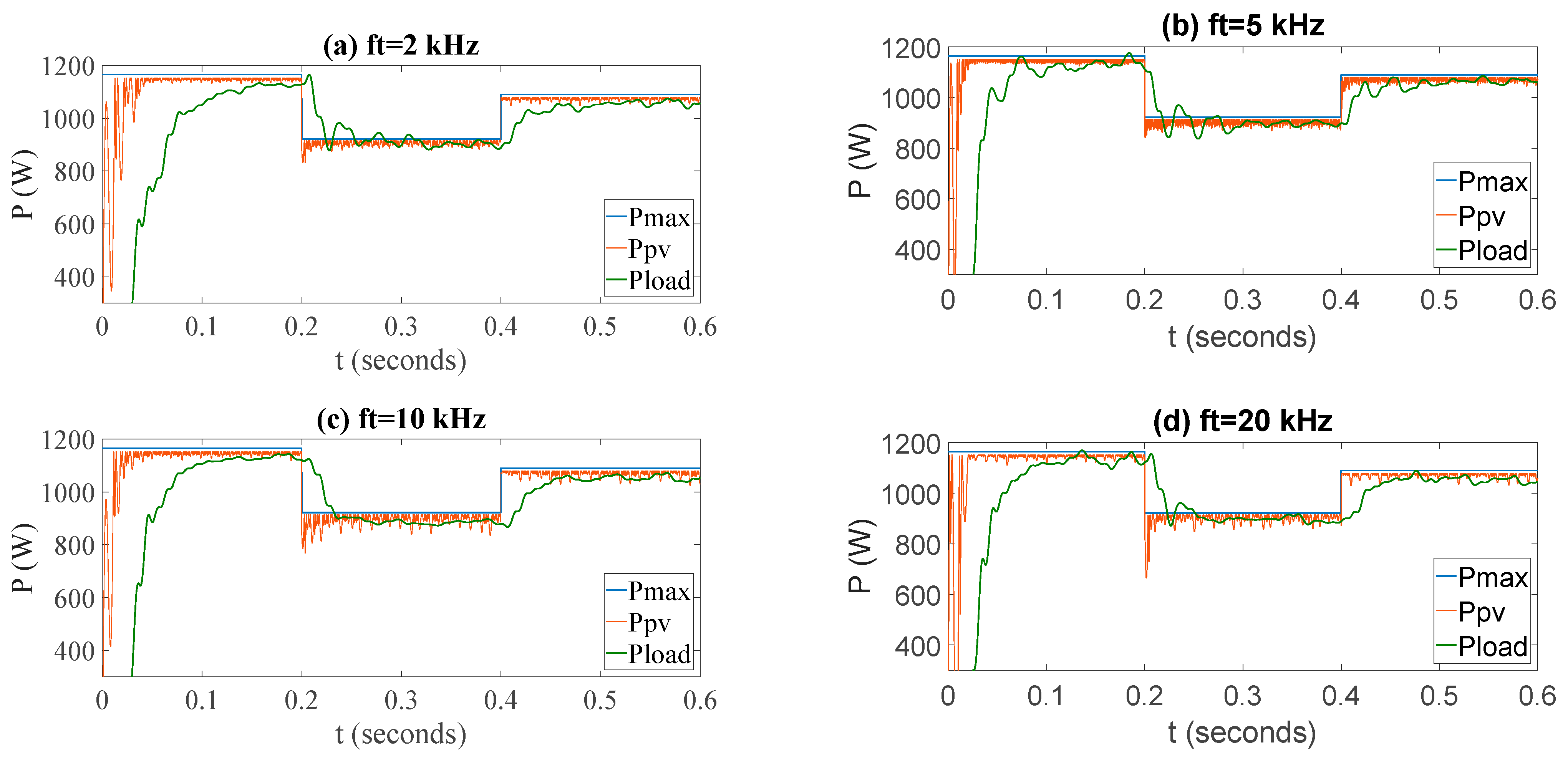
3.1. System Behavior at Different Commutation Frequencies

The values of the rest of parameters are listed in Table 3.
The parameters of the system have been optimized by GAs at four different commutation frequencies for the inverter stage, and their power dynamics are presented in Figure 6. In this figure, convergence of the MPPT algorithm for P p v (red line) can be observed. In this case, the best performance occurs at a frequency of 5 kHz, followed by 10, 20, and 2 kHz.
However, another dynamic is the oscillating power, with the best performance and lowest power ripple in Figure 6a. In the case of transferring power to the load (green line), Figure 6c,d display softer behavior.
Table 4 presents the analytical results of the four cases, showing the value of each index and also the global performance index J and efficiency, with f t = 5   k H z being the case that presents the best global performance.
Comparing the results obtained at each of the carrier signal switching frequencies, f t = 5   k H z is selected and then re-optimized with a population of 50 generations, evaluating 4081 cases and obtaining the best result with the following values: C 1 = 273   μ F , L = 36   m H , C 2 = 394   μ F , L f = 36   m H , C f = 254   μ F , T s = 55.866   μ s , k p = 3.6528 × 10 4 , k i = 0.0198 .
The dynamics of the system variables are illustrated below. Figure 7a presents the tracking of solar power. It demonstrates how SMC does excellent work, responding very fast under irradiation changes. Figure 7b shows the power transferred to the load by the PI controller, demonstrating good convergence speed and robustness under these irradiation changes. Control signals u and m are presented in Figure 7c,d, respectively.
Once the system has been optimized, we compare our proposed approach with the InCond MPPT algorithm and a heuristic base case using SMC. To achieve this, a load of R = 3 ohms is applied to the system, generating the dynamics shown in Figure 8. The optimized SMC algorithm proposed in this work demonstrates superior performance in capturing solar power compared with other techniques, as can be seen in Figure 8a. Figure 8b illustrates the transfer of captured power to the load. The incremental conductance algorithm exhibits the poorest performance, followed by the non-optimized SMC, which shows oscillatory behavior. The best results are achieved with our optimized system.
Table 5 shows the reached values for each performance index, the fitness function value, and the global efficiency for each case. Comparing these results, our proposal reaches a global efficiency of 95.8%, which is 1.14% higher than standard SMC, and 11.8% higher than the incremental conductance algorithm.
In the case of the energy quality delivery to the load, the THD values of the current and voltage of the filtering stage are shown in Table 5, where the best performance corresponds to the optimized sliding mode control with i L f T H D = 3.07 % and V c f T H D = 2.59 % . The incremental conductance MPPT algorithm has values of 4.10% and 3.13%, respectively, and in the non-optimized SMC, they are 3.6 and 2.92%.

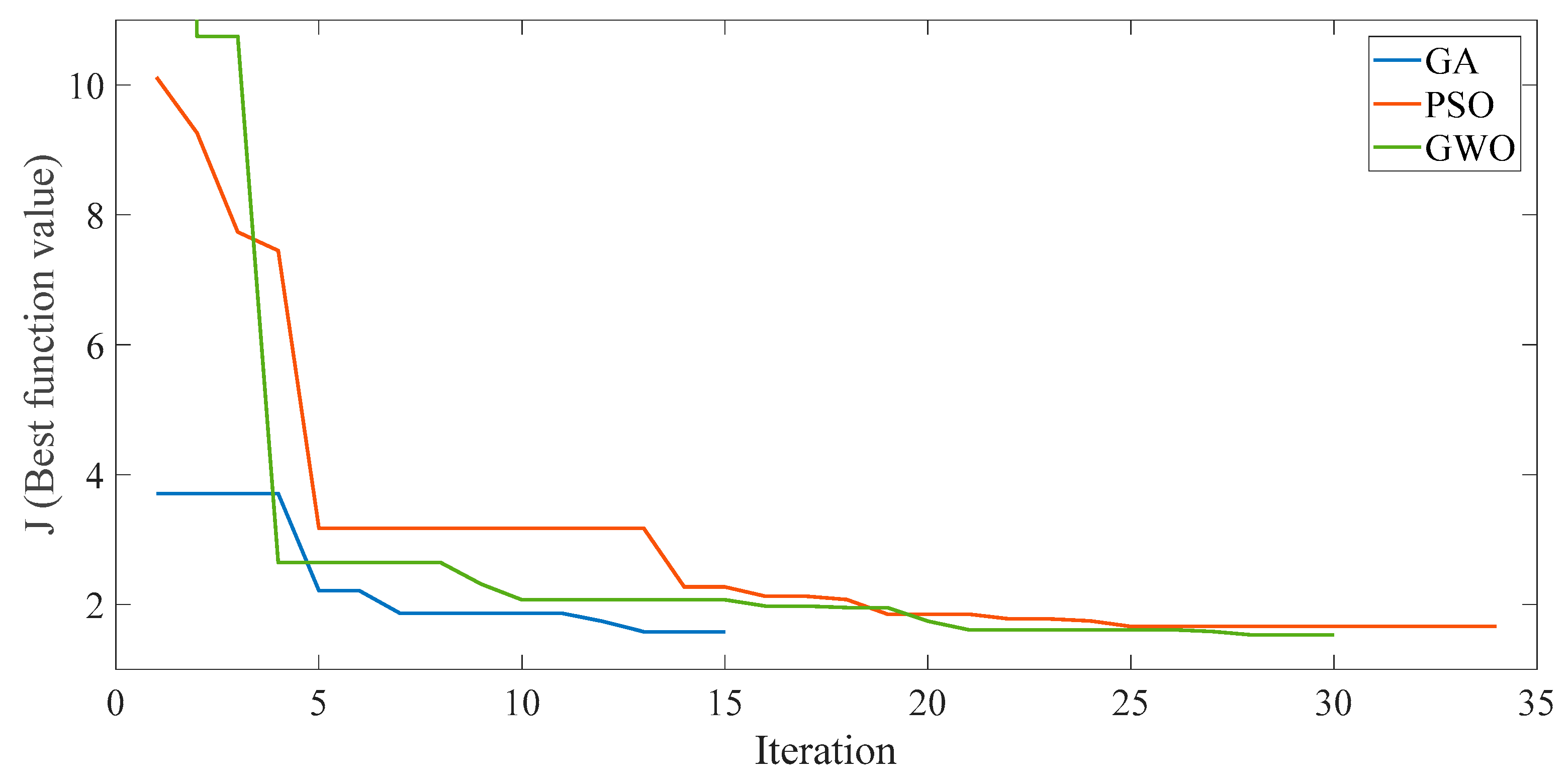
3.2. Comparison with Others Optimization Algorithms

In the literature, there are many other optimization algorithms, such as Particle Swarm Optimization (PSO), which has been implemented in [30], where researchers combine this technique with traditional ones like perturb and observe and incremental conductance (e.g., PSO-P&O and PSO-IC), finding an optimal step size, which is variable depending of the weather conditions, and increasing the efficiency of the system. Another optimization algorithm that has been programmed for the DC-DC buck converter is the earthquake optimization algorithm [23], where the fitness function is the sum of the errors of the output voltage and the inductor current, finding the optimal parameters of capacitors and inductors, like in our case.
In the previous section, eight parameters of the two-stage single-phase inverter were optimized with the GA. Now, the results are compared with the PSO technique and gray wolf optimization to determine which optimization algorithm has a better performance among these types of systems.

3.2.1. Particle Swarm Optimization

PSO was proposed by Kennedy in 1995 [31], emulating the behavior of insects. One difference with GAs is that PSO performs a more precise search around the local minimums that the GA finds, being able to find global minimums in the search area. The parameters of the algorithm are SwarmSize = 20, MaxStallIterations = 180, MinNeighborsFraction = 0.25, and FunctionTolerance = 0.01 with a random number generation.

3.2.2. Gray Wolf Optimizer

The GWO technique was presented by Seyedali Mirjalili in 2014 [32]. It was inspired the way wolves organize themselves to hunt. Hierarchically, they are classified into four types of wolves, alpha, beta, delta, and omega, implementing three stages for the house of prey: search, encirclement, and attack. The parameters of the algorithm are SearchAgents_no = 20 and Max_iteration = 30;

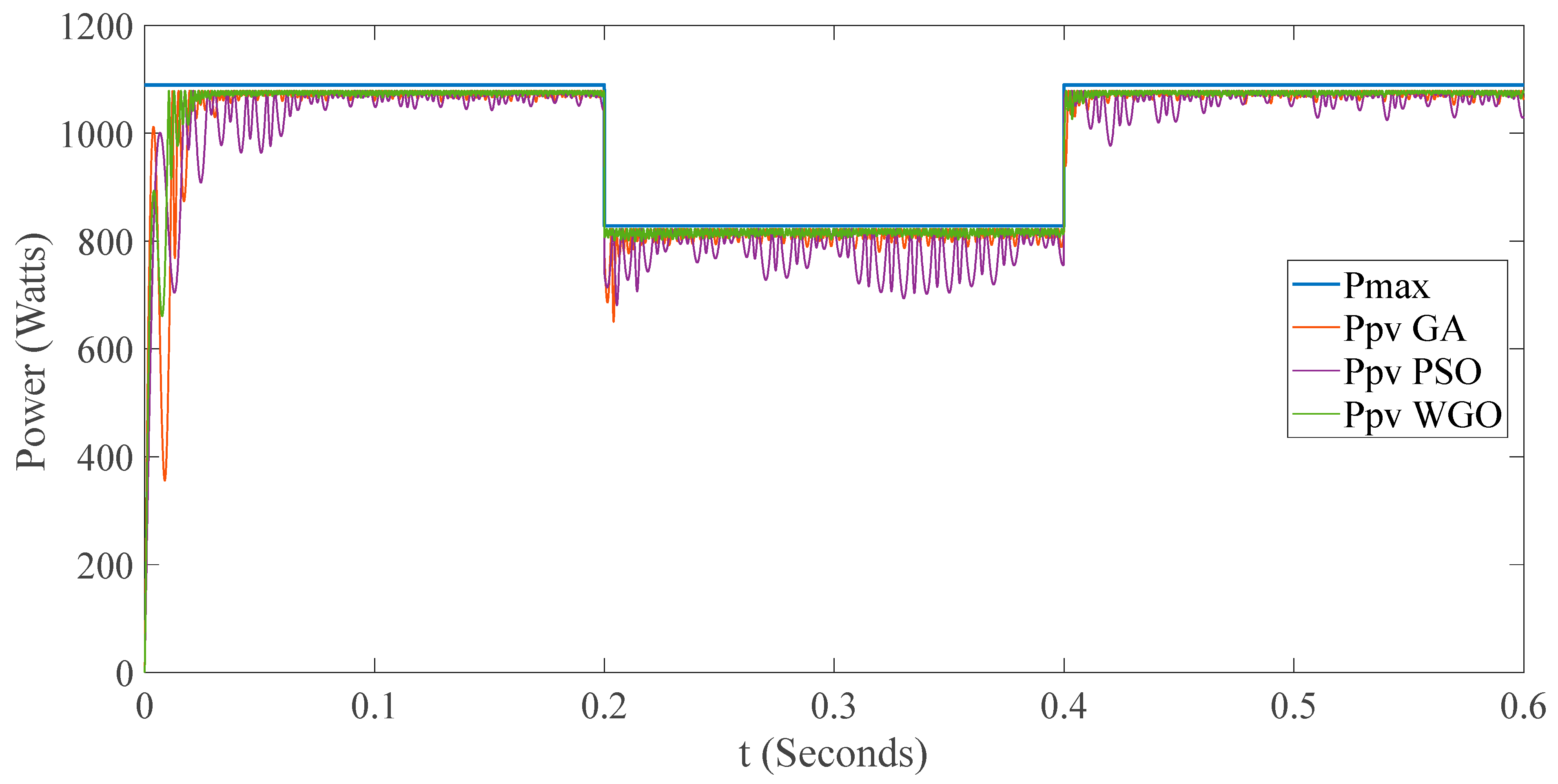
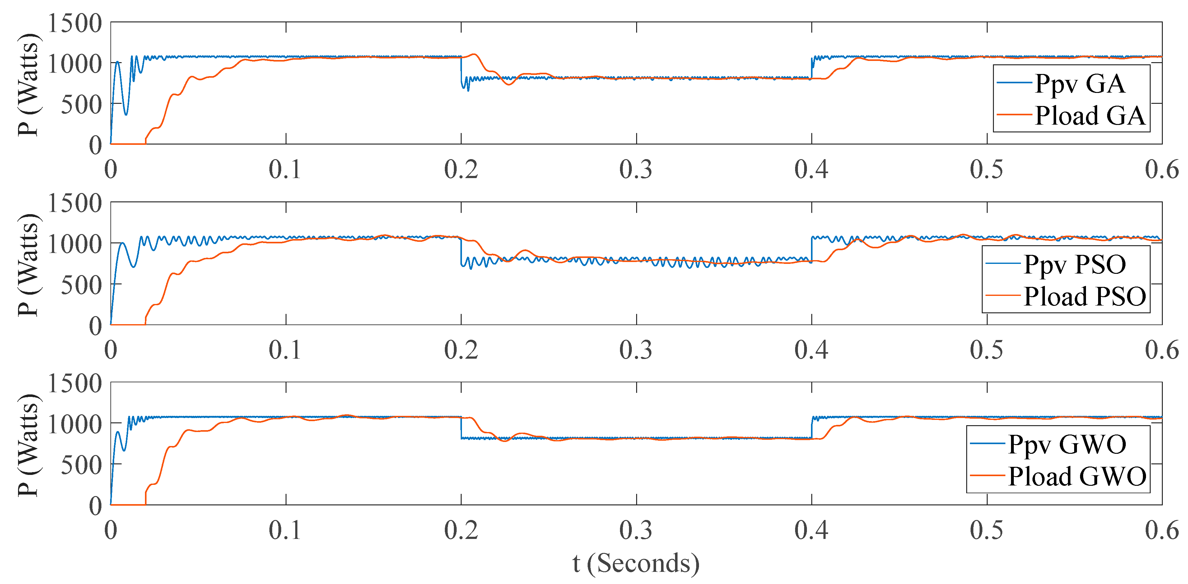
3.3. Results of the GA, PSO and GWO Implementation

In Figure 9, the evolution of the fitness function for the three optimization algorithms is shown, observing that the GA is faster than PSO and GWO, but GWO reaches a minimum value before PSO.
Table 6 presents an analysis of the three algorithms, comparing different performance parameters like the best objective function value, where GWO reaches the lowest value; however, it is the slower algorithm. GA has the least number of iterations. The optimized parameters of capacitances and inductances are given, as well as the step time and the proportional and integral constants of the PI control.
The dynamics of the power captured by the photovoltaic system can be observed in Figure 10, where the system optimized with GWO presents the lower ripple, and PSO has the biggest one. The graph shows how efficient each algorithm is at reaching the maximum available solar power P m a x . It appears that GWO reaches a higher P p v value earlier compared to the GA and PSO, suggesting that GWO might be more efficient in achieving optimal power levels quickly. This indicates its superiority in scenarios where rapid convergence to optimal solutions is required. The GA and PSO, while effective, may take longer to reach similar power levels, which could be a consideration in time-sensitive applications. Table 7 presents the integral square error (ISE) and integral absolute error (IAE), which show the superiority of the GWO method.
Figure 11 shows the captured power transferred to the load for each case. The GWO algorithm presents a smoother dynamic, followed by the GA and, with the worst behavior, the PSO algorithm. The graph shows the power output for both P p v and P l o a d over time. The GA and GWO algorithms are compared, with GWO showing a more stable and possibly higher power output for Ppv compared to the GA. The better stability and higher power output of the GWO algorithm suggest that it might be more effective in managing photovoltaic systems. The comparison of P l o a d under each algorithm indicates how well each algorithm can balance the load, which is crucial for efficient power management.
Finally, Table 8 presents the performance indexes of each optimization algorithm with global efficiency, where GWO has the best result. We note that, in the table, index 1 refers to the efficiency of the solar power caption. In other words, it is the performance of the MPPT algorithm. GWO is the method with the best performance with 21.99. Index 2 refers to the power transfer from PV modules to the inverter stage, reflecting the commutation power losses. In this case, the GWO method also has the best performance. Finally, indices 3 and 4 refer to current and voltage power quality, respectively, reflecting the THD content of each signal. Again, GWO is proven to be the best method to optimize the performance indexes.

4. Conclusions and Discussion

In recent years, different approaches have been carried out to improve the performance of electronic converters applied to photovoltaic systems, where energy quality and efficiency are mandatory [24,25]. In this work, firstly, a two-stage single-phase inverter has been modeled, which includes switching losses in the boost stage. Next, four performance indexes have been defined, allowing us to evaluate the efficiency and effectiveness in each stage of the system.
Then, two control techniques were implemented, one using a sliding mode control technique for the boost stage and the other using classic PI control for the inverter stage. The gains of the PI control, the integration step for the sliding mode control, and the LC parameters of the system were optimized by the Genetic Algorithm, obtaining an improvement in the overall efficiency of the system. With the optimized values, the dynamics at four switching frequencies of the inverter stage were simulated and compared, finding the best results at a frequency of 5 kHz. The proposal of having four performance indexes allowed us to optimize and evaluate the overall efficiency of the system, from the capture of solar energy to delivering the energy to the load, with an acceptable quality and efficiency. Our GA-optimized control method reached better results than the incremental conductance algorithm and a standard SMC base case. Finally, the other two optimization algorithms (PSO and GWO) were implemented and compared with the GA, analyzing different parameters to evaluate their performance and finding that GWO reached better efficiency than the other two analyzed methods.
As a future work, the authors have interest in implementing the system in a real-time simulator to evaluate practical applications and apply this methodology to other converter topologies.

Author Contributions

Conceptualization, A.C.-M. and M.C.-N.; methodology, A.C.-M. and M.C.-N.; software, A.C.-M. and M.C.-N.; validation, A.C.-M., J.S.A.-S. and J.A.D.-N.; formal analysis, J.S.A.-S. and J.A.D.-N.; investigation, A.C.-M. and J.S.A.-S.; resources, A.C.-M. and M.C.-N.; data curation, J.S.A.-S.; writing—original draft preparation, A.C.-M.; writing—review and editing, J.S.A.-S.; visualization, M.C.-N. and J.A.D.-N.; supervision, J.A.D.-N.; project administration, A.C.-M.; All authors have read and agreed to the published version of the manuscript.

Funding

This research received no external funding.

Institutional Review Board Statement

Not applicable.

Informed Consent Statement

Not applicable.

Data Availability Statement

All data are specified in the article.

Acknowledgments

The first author thank the Secretaría de Ciencia, Humanidades, Tecnología e Innovación (SECIHTI-Mexico) for the scholarship awarded with CVU number 98169 of the National System of Researchers.

Conflicts of Interest

The authors declare no conflicts of interest.

References

  1. Karami-Mollaee, A.; Barambones, O. Dynamic Sliding Mode Control of DC-DC Converter to Extract the Maximum Power of Photovoltaic System Using Dual Sliding Observer. Electronics 2022, 11, 2506. [Google Scholar] [CrossRef]
  2. Abid, R.; Mahjoub, S.; Masmoudi, F.; Derbel, N. MPPT Control Strategies for Photovoltaic Applications: Algorithms and Comparative Analysis. In Proceedings of the 16th International Multi-Conference on Systems, Signals and Devices (SSD), Istanbul, Turkey, 21–24 March 2019; pp. 566–572. [Google Scholar] [CrossRef]
  3. Flota-Bañuelos, M.; Espinosa-Trujillo, M.; Cruz-Chan, J.; Kamal, T. Experimental Study of an Inverter Control for Reactive Power Compensation in a Grid-Connected Solar Photovoltaic System Using Sliding Mode Control. Energies 2023, 16, 853. [Google Scholar] [CrossRef]
  4. Dhar, S.; Dash, P.K. Adaptive backstepping sliding mode control of a grid interactive PV-VSC system with LCL filter. Sustain. Energy Grids Netw. 2016, 6, 109–124. [Google Scholar] [CrossRef]
  5. Cortes-Vega, D.; Alazki, H. Robust maximum power point tracking scheme for PV systems based on attractive ellipsoid method. Sustain. Energy Grids Netw. 2021, 25, 100410. [Google Scholar] [CrossRef]
  6. Zhu, Y.; Fei, J. Adaptive Global Fast Terminal Sliding Mode Control of Grid-connected Photovoltaic System Using Fuzzy Neural Network Approach. IEEE Access 2017, 5, 9476–9484. [Google Scholar] [CrossRef]
  7. Zeb, K.; Islam, S.U.; Din, W.U.; Khan, I.; Ishfaq, M.; Busarello, T.D.C.; Ahmad, I.; Kim, H.J. Design of Fuzzy-PI and Fuzzy-Sliding Mode Controllers for Single-Phase Two-Stages. Electronics 2019, 8, 520. [Google Scholar] [CrossRef]
  8. Rehman, A.U.; Khan, L.; Ali, N.; Alam, Z.; Khan, Z.A.; Khan, M.A. Soft Computing Technique based Nonlinear Sliding Mode Control for Stand-Alone Photovoltaic System. In Proceedings of the International Conference on Emerging Trends in Smart Technologies (ICETST), Karachi, Pakistan, 26–27 March 2020. [Google Scholar] [CrossRef]
  9. Padmanaban, S.; Priyadarshi, N.; Holm-Nielsen, J.B.; Bhaskar, M.S.; Azam, F.; Sharma, A.K.; Hossain, E. A novel modified sine-cosine optimized MPPT algorithm for grid integrated PV system under real operating conditions. IEEE Access 2019, 7, 10467–10477. [Google Scholar] [CrossRef]
  10. Guo, B.; Su, M.; Sun, Y.; Wang, H.; Dan, H.; Tang, Z.; Cheng, B. A Robust Second-Order Sliding Mode Control for Single-Phase Photovoltaic Grid-Connected Voltage Source Inverter. IEEE Access 2019, 7, 53202–53212. [Google Scholar] [CrossRef]
  11. Guo, B.; Su, M.; Sun, Y.; Wang, H.; Liu, B.; Zhang, X.; Pou, J.; Yang, Y.; Davari, P. Optimization Design and Control of Single-Stage Single-Phase PV Inverters for MPPT Improvement. IEEE Trans. Power Electron. 2020, 35, 13000–13016. [Google Scholar] [CrossRef]
  12. Chang, E.-C. High-performance pure sine wave inverter with robust intelligent sliding mode maximum power point tracking for photovoltaic applications. Micromachines 2020, 11, 585. [Google Scholar] [CrossRef]
  13. Cortajarena, J.A.; Barambones, O.; Alkorta, P.; De Marcos, J. Sliding mode control of grid-tied single-phase inverter in a photovoltaic MPPT application. Sol. Energy 2017, 155, 793–804. [Google Scholar] [CrossRef]
  14. Yang, B.; Yu, T.; Shu, H.; Zhu, D.; Sang, Y.; Jiang, L. Passivity-based fractional-order sliding-mode control design and implementation of grid-connected photovoltaic systems. J. Renew. Sustain. Energy 2018, 10, 043701. [Google Scholar] [CrossRef]
  15. Meng, Z.; Shao, W.; Tang, J.; Zhou, H. Sliding-mode control based on index control law for MPPT in photovoltaic systems. CES Trans. Electr. Mach. Syst. 2018, 2, 303–311. [Google Scholar] [CrossRef]
  16. Abdelhalim, B.; Abdelhak, B.; Noureddine, B.; Thameur, A.; Abdelkader, L.; Layachi, Z. Optimization of the fuzzy MPPT controller by GA for the single-phase grid-connected photovoltaic system controlled by sliding mode. AIP Conf. Proc. 2019, 2190, 020003. [Google Scholar] [CrossRef]
  17. Feshara, H.F.; Ibrahim, A.M.; El-Amary, N.H.; Sharaf, S.M. Performance evaluation of variable structure controller based on sliding mode technique for a grid-connected solar network. IEEE Access 2019, 7, 84349–84359. [Google Scholar] [CrossRef]
  18. Ravikant, U.; Singh, V.; Rani, A. PV fed sliding mode controlled SEPIC converter with single phase inverter. In Proceedings of the 5th International Conference on Communication and Electronics Systems ICCES, Coimbatore, India, 10–12 June 2020; Institute of Electrical and Electronics Engineers Inc.: Piscataway, NJ, USA, 2020; pp. 20–25. [Google Scholar] [CrossRef]
  19. Menaga, D.; Sankaranarayanan, V. Performance comparison for grid connected photovoltaic system using sliding mode control. J. King Saud Univ.-Eng. Sci. 2020, 33, 276–283. [Google Scholar] [CrossRef]
  20. Kumar, N.B.; Urundady, V. Sliding Mode Controller with Integral Action for DC-Link Voltage Control of Grid-Integrated Domestic Photovoltaic Systems. Arab. J. Sci. Eng. 2020, 45, 6583–6600. [Google Scholar] [CrossRef]
  21. Ali, H.G.; Vilanova, R.; Pelez-Restrepo, J. Perturb Observe based Adaptive Sliding Mode MPPT Control of Solar Photovoltaic System. In Proceedings of the IEEE International Conference on Environment and Electrical Engineering and 2020 IEEE Industrial and Commercial Power Systems Europe, EEEIC/I and CPS Europe, Madrid, Spain, 9–12 June 2020; Institute of Electrical and Electronics Engineers Inc.: Piscataway, NJ, USA, 2020. [Google Scholar] [CrossRef]
  22. Coronado-Mendoza, A.; Pérez-Cisneros, M.A.; Domínguez-Navarro, J.A.; Osuna-Enciso, V.; Zúñiga-Grajeda, V.; Gurubel-Tun, K.J. Dynamic phasors modeling for a single phase two stage inverter. Electr. Power Syst. Res. 2016, 140, 854–865. [Google Scholar] [CrossRef]
  23. Mendez-Flores, E.; Ortiz, A.; Macias, I.; Molina, A. Experimental Validation of an Enhanced MPPT Algorithm and an Optimal DC–DC Converter Design Powered by Metaheuristic Optimization for PV Systems. Energies 2022, 15, 8043. [Google Scholar] [CrossRef]
  24. Bouhadji, F.; Bouyakoub, I.; Mehedi, F.; Kacemi, W.M.; Reguieg, Z. Optimization of grid power quality using third order sliding mode controller in PV systems with multilevel inverter. Energy Rep. 2024, 12, 5177–5193. [Google Scholar] [CrossRef]
  25. Alia, I.; Merzouk, I.; Rezaoui, M.M.; Rezk, H.; Lashab, A. Output current observation and control of grid-connected modular multilevel converter using a simplified super twisting algorithm sliding mode. Results Eng. 2025, 25, 104280. [Google Scholar] [CrossRef]
  26. Lupangu, C.; Saha, A.K.; Bansal, R.C.; Justo, J.J. Critical Performance Comparison Between Single-Stage and Two-Stage Incremental Conductance MPPT Algorithms for DC/DC Boost-Converter Applied in PV Systems. Electr. Power Compon. Syst. 2022, 50, 207–222. [Google Scholar] [CrossRef]
  27. Eltamaly, A.M. A novel musical chairs algorithm applied for MPPT of PV systems. Renew. Sustain. Energy Rev. 2021, 146, 111135. [Google Scholar] [CrossRef]
  28. Eltamaly, A.M. A Novel Strategy for Optimal PSO Control Parameters Determination for PV Energy Systems. Sustainability 2021, 13, 1008. [Google Scholar] [CrossRef]
  29. Coronado-Mendoza, A.; Bernal-Agustín, J.L.; Domínguez-Navarro, J.A. Photovoltaic boost converter system with dynamic phasors modelling. Electr. Power Syst. Res. 2011, 81, 1840–1848. [Google Scholar] [CrossRef]
  30. Ibrahim, M.H.; Ang, S.P.; Dani, M.N.; Rahman, M.I.; Petra, R.; Sulthan, S.M. Optimizing Step-Size of Perturb & Observe and Incremental Conductance MPPT Techniques Using PSO for Grid-Tied PV System. IEEE Access 2023, 11, 13079–13090. [Google Scholar] [CrossRef]
  31. Kennedy, J.; Eberhart, R. Particle swarm optimization. In Proceedings of the ICNN’95—International Conference on Neural Networks, Perth, Australia, 27 November–1 December 1995; IEEE: Piscataway, NJ, USA, 1995; Volume 4, pp. 1942–1948. [Google Scholar]
  32. Mirjalili, S.; Mirjalili, S.M.; Lewis, A. Grey Wolf Optimizer. Adv. Eng. Softw. 2014, 69, 46–61. [Google Scholar] [CrossRef]
Figure 1. Photovoltaic inverter system.
Energies 18 01911 g001
Figure 2. PV curves at different irradiation levels.
Energies 18 01911 g002
Figure 3. Sliding mode phases.
Energies 18 01911 g003
Figure 4. Simulink implementation of the sliding mode control.
Energies 18 01911 g004
Figure 5. Optimization process.
Energies 18 01911 g005
Figure 6. Powers dynamics at different frequencies.
Energies 18 01911 g006
Figure 7. Optimized variables dynamics.
Energies 18 01911 g007
Figure 8. Power dynamics of the three compared cases.
Energies 18 01911 g008
Figure 9. Evolution of the fitness function with optimization algorithms.
Energies 18 01911 g009
Figure 10. Dynamics of the MPPT algorithms.
Energies 18 01911 g010
Figure 11. Dynamics of the transferred power to the load.
Energies 18 01911 g011
Table 1. Performance indexes for MPPT algorithms and PV systems.
AuthorTHDTracking
Error
Convergence SpeedEfficiencyRobustnessDC Bus
[4]x x
[6] x
[13]x x x
[14] x x
[15] x
[7]xx xxx
[9]
[2] xx
[16] x x
[17] x x
[10]xx xx
[8] xxxxx
[18]xxx
[19] xx
[20]x x x
[21] x x
[11]xxxx x
[12]x x
[5]xxx x
[22]xxxxx
[23]xxxxx
[1] xx
[24]x xxx
[25]xx x x
Table 2. Optimized parameters values.
Parameter Value
f T
Incremental ConductanceBase Case2 kHz5 kHz10 kHz20 kHz
C 1 (µF)2000250235150240110
C 2 (µF)2000250669539526551
C f (µF)250250602238452374
L (mH)101024192035
L f (mH)251539344647
T s (µS)505056615589
Kp0.0000140.000148.4656 × 10−44.1857 × 10−44.7661 × 10−40.0014
Ki0.04470.008470.02560.02110.03600.0447
δ 0.002
Note: The number of function evaluations was 481.
Table 3. Parameters of the PV array.
ParameterValueParameterValue
Ppv320 WNpp1
Isc9.26 ARsl0.5
Vocm45.3 VR10
Nps4
Table 4. Values of the indexes and results.
Index f T
2 kHz5 kHz10 kHz20 kHz
P i n d e x 1 32.578030.965837.188035.7368
P i n d e x 2 105.504276.990894.570687.3150
P i n d e x 3 0.02260.02780.02330.0297
P i n d e x 4 0.01980.02160.01820.0217
J1.53321.42891.49422.0137
Global efficiency (%)89.0891.3689.7190.70
Table 5. Results comparison of the three cases.
IndexIncremental
Conductance
Non-Optimized SMCOptimized SMC
P i n d e x 1 72.202630.409518.4982
P i n d e x 2 98.447534.323929.9648
P i n d e x 3 0.04100.03600.0307
P i n d e x 4 0.03130.02920.0259
J9.11661.09910.4409
Global efficiency (%)84.4294.4795.80
Table 6. Summary of PSO and GWO model simulation.
VariableGAPSOGWO
Best objective function value1.578871.66201.529
Execution time (s)7897185.16134640.9
Number of iterations/generations143230
The number of function evaluations1201740
C 1   μ F 198344232
L   m H 274424
C 2   μ F 561617400
L f   m H 434250
C f   μ F 475417180
T s   μ s 6012541
k p 0.000580.00066840.0004326
k i 0.02700.026130.02473
Table 7. Comparison of errors with the three optimization tools.
GAPSOGWO
I S E = 0 e 2 t d t 354939742181
I A E = 0 e t d t 17.1527.0713.18
Table 8. Comparison of the performance indexes with the three optimization tools.
GAPSOGWO
J1
P i n d e x 1 28.629145.221821.99
P i n d e x 2 91.299699.600078.5964
P i n d e x 3 0.02530.03290.0284
P i n d e x 4 0.02140.02550.0227
J1.578871.66201.529
Global efficiency (%)90.017688.632391.3961
Disclaimer/Publisher’s Note: The statements, opinions and data contained in all publications are solely those of the individual author(s) and contributor(s) and not of MDPI and/or the editor(s). MDPI and/or the editor(s) disclaim responsibility for any injury to people or property resulting from any ideas, methods, instructions or products referred to in the content.

