1. Introduction
The use of electric vehicles (EVs) in the last decade marks a significant milestone in the evolution of the automotive industry and represents a fundamental advance towards more sustainable transportation solutions [
1]. Over the last years, EVs have captured the attention of both the vehicle manufacturers and consumers, with a notable increase in the deployment of EVs in all markets. According to the report of the International Energy Agency (IEA), nearly one in five cars sold in 2023 was electric. The sales of electric vehicles neared 14 million in 2023, 95% of which were in China, Europe, and the United States [
2]. This surge in popularity is driven by a confluence of technological advancements, environmental concerns, and supportive government policies.
Regarding the technological innovations, research on battery systems have played a crucial role in propelling the growth of electric vehicles. Liu et al. [
3] made a thorough review of the batteries and battery management technologies for hybrid and pure EVs. A quick, simple, and safe battery recharge ensures a positive user experience, facilitating a swift transition to sustainable mobility. In this context, advances in lithium-ion batteries have led to substantial improvements in energy density, charging times, and overall vehicle range, making EVs more practical and appealing to a broader audience. Jaime-Barquero et al. [
4] analyzed the existing methodologies to detect degradation modes in lithium batteries. Estimation models of the state of charge (SoC) and state of health (SoH) of lithium-ion batteries, as the one presented by Huang et al. [
5] becomes also very important for safe and reliable EVs.
Environmental considerations are also a major driving force behind the rise of electric vehicles. With the increasing urgency to combat climate change and reduce greenhouse gas emissions, EVs offer a cleaner alternative to traditional internal combustion engine vehicles. By running on electricity, which can be sourced from renewable energy, electric vehicles significantly cut down on air pollution and help mitigate the impact of fossil fuels on the environment [
6]. This becomes crucial for urban areas plagued by pollution and for global efforts to meet climate targets set by international agreements. In this regard, the study of Guo et al. [
7] showed a positive correlation between the air pollution and the sales of EVs. Government policies and incentives have further accelerated the adoption of electric vehicles. Many countries and regions are implementing measures such as tax rebates, subsidies, and stringent emission regulations to encourage both consumers and manufacturers to embrace electric mobility [
8,
9,
10].
However, in order to achieve sustainable growth in the deployment of EVs, it is essential for all nations to increase the development of the charging infrastructure. This issue addresses one of the primary concerns for potential EV consumers to enable them to recharge their vehicles efficiently. For that reason, establishing a widespread network of EV charging points is indispensable to support the continued growth and integration of EVs [
11]. In addition, it should be noted that public access to these facilities is particularly important, as many users do not have access to private garage spaces. To that end, optimizing the location and capacity of electric vehicle charging stations (EVCSs) and renewable energy sources (RESs) within direct current (DC) microgrids is essential, addressing multiple objectives such as operational reliability, cost-effectiveness, power loss minimization, and voltage stability [
12]. A modified version of the teaching–learning-based optimization (TLBO) algorithm is employed to identify optimal system configurations, leading to enhanced voltage regulation and minimized power losses [
13]. Additionally, various studies highlight the dual challenge of environmental degradation and fuel shortages, reaching the conclusion that implementing IoT-enabled smart charging systems presents a promising approach to improving battery management efficiency. Wireless integration of IoT functionalities into battery systems also facilitates real-time performance monitoring, improving both operational reliability and safety [
14]. Qahtan et al. [
15] reviewed the intelligent EV charging networks supported by IoT, analyzing various charging methods and highlighting the role of IoT technologies, particularly mobile applications, in simplifying station location and potentially accelerating the adoption of EVs. Çakir et al. [
16] studied the effect of electric vehicle charging stations on power grids, developing a new model to assess the impact of the increasing number of EVs on the power grid in the province of Sivas in Turkey. Moreover, several works offer comprehensive evaluations of EVs, covering aspects such as charging infrastructures and battery technologies, and comparing commercial models with prototypes. The study of Rajole et al. [
17] categorizes different types of charging stations and examines their effects on power grid operations, proposing a scalable and economically viable approach for future deployment to accommodate the rising demand for EVs. An alternative approach involves designing an EVCS powered by RESs such as wind turbines and solar photovoltaic systems, in response to the growing need for sustainable transportation. This solution seeks to minimize grid dependency by harnessing the excess energy from these sources and applying an energy management strategy [
18]. Another fundamental aspect that must be taken into account for suitable recharging is a proper vehicle and charging point programming. This approach emphasizes Type 2 and Type 3 charging systems, which support both single-phase and three-phase charging stations. In an EV charging station, unlike combustion gas stations, a communication between vehicle and the charging station is required to ensure a safe and reliable charging process [
19]. However, there are still charging points that remain unusable due to persistent communication failures.
In that sense, embedded systems emerged as a potential solution to address these communication issues. Edge computing describes a model in which data are processed closer to the source, reducing dependence on centralized cloud servers [
20]. Embedded systems are typically developed to execute specific tasks, often within the constraints of real-time operational environments [
21]. The software that powers these systems is known for its high efficiency and minimal resource requirements. A widely recognized example is Arduino, an open-source platform that provides user-friendly hardware and software components, making it particularly suitable for educational and prototyping applications [
22]. Due to its accessible development kits and strong community support, Arduino has become a popular choice in embedded system design [
23]. Its integrated development environment (IDE) has greatly simplified the code compilation process, contributing to its widespread adoption.
Several initiatives aim to design electrical energy monitoring devices for battery-powered EVs, focusing on the precise measurement of key parameters such as power, voltage, current, and battery temperature. In this context, the review of Malele et al. [
24] provides a comprehensive analysis of microcontroller-based BMS advancements, highlighting control strategies, efficiency techniques, and challenges in hybrid energy systems. The study of Garg et al. [
25] showed an Arduino-driven monitoring system equipped with sensors to assess EV battery parameters. The system featured real-time data visualization on an LCD screen, contributing to improved operational safety and efficiency in EV applications. Selvabharathi et al. [
26] used an Arduino Uno microcontroller to develop an IoT-enabled battery management system (BMS) for real-time monitoring of EVs batteries and to process and transmit battery health data. According to Insia et al. [
27], the integration of Arduino, sensors, and wireless communication makes the BMS cost-effective and scalable for various EV applications. The work of Calvinus et al. [
28] also proposed a BMS using an Arduino microcontroller to improve the charging of EV batteries. Their results showed that the current measurement was more accurate than the voltage measurement, while the temperature measurement achieved 97% accuracy. The study of Rusli et al. [
29] demonstrated how an ESP32 microcontroller can efficiently manage and transmit real-time energy data for EVs. The system significantly enhanced energy monitoring, optimization, and decision-making, proving valuable for energy-efficient vehicle competitions and broader EV applications. The ATmega328P microcontroller was used as the core-processing unit by Sasirekha et al. [
30], handling sensor data acquisition, power management, and IoT communication. Their proposed system ensured a better battery performance, extended lifespan, and reduced environmental impact by optimizing EV battery health monitoring. The recent work of Gozuoglu [
31] also presents a low-cost IoT-enabled BMS, using a ESP32 microcontroller, for monitoring the state of charge and state of health of lithium-ion and lithium-polymer batteries.
This paper delves into the analysis of the installation and control of an internal charger, initially described by Ramos-Hernanz et al. [
32] and Aramendia et al. [
33]. Beyond verifying its functionality, the system’s code has been refined with minor enhancements to ensure stable operational margins. This work aims to develop a control strategy for the on-board charger within the EV. This study introduces an intelligent EV charging management approach implemented through a cost-effective solution. The key contributions and novelties of this work include the implementation of a cost-effective charging control system using an Arduino MEGA 2560 microcontroller (Elegoo, Inc., Shenzhen, China), reducing hardware expenses while maintaining performance. Moreover, it includes the integration of a multi-stage charging strategy, regulating current flow to prevent overcharging and to improve battery longevity, as well as a real-time monitoring and safety mechanisms, ensuring controlled charging by detecting voltage differences and stopping the process if unsafe conditions arise. To support this, the implementation will include charge modulation alongside accurate and controlled charging mechanisms. However, certain limitations arise from the initial design choices, including a maximum charging current of 3 A. Moreover, the use of a 12 V battery restricts its role solely to the charging process, as dictated by the specifications of the selected power regulator. This paper is organized as follows:
Section 2 outlines the components used in the project, whereas
Section 3 provides a detailed explanation of the battery charging process. The performance of the recharge curve and the limitations and improvement proposals are discussed in
Section 4 and
Section 5, respectively. Lastly,
Section 6 summarizes the key conclusions drawn from this study.
2. Materials and Methods
Developing the internal charger for the vehicle requires the implementation of custom programming. To facilitate this, a hardware platform that offers both ease of use and sufficient processing capability is essential. The Arduino MEGA 2560 board, shown in
Figure 1, was selected for this role due to its versatility. It handles all control operations, including executing commands, monitoring voltage levels from both the battery and charger, and adjusting the charging process accordingly.
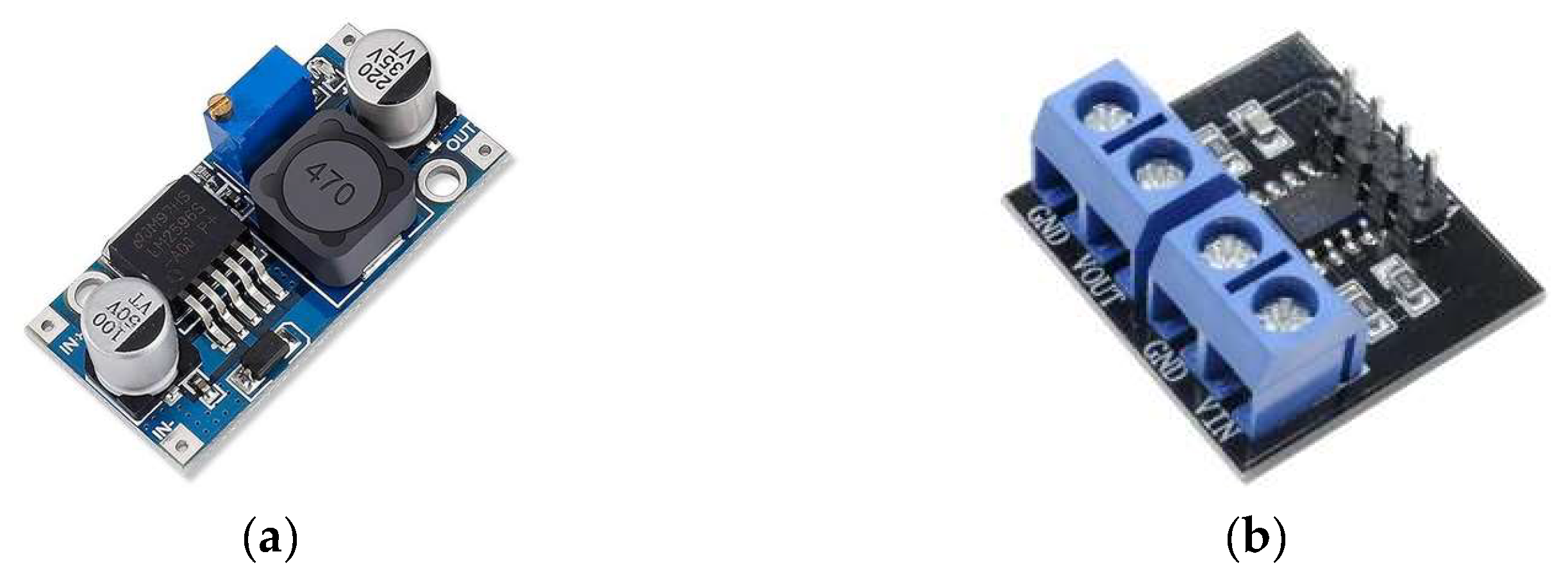
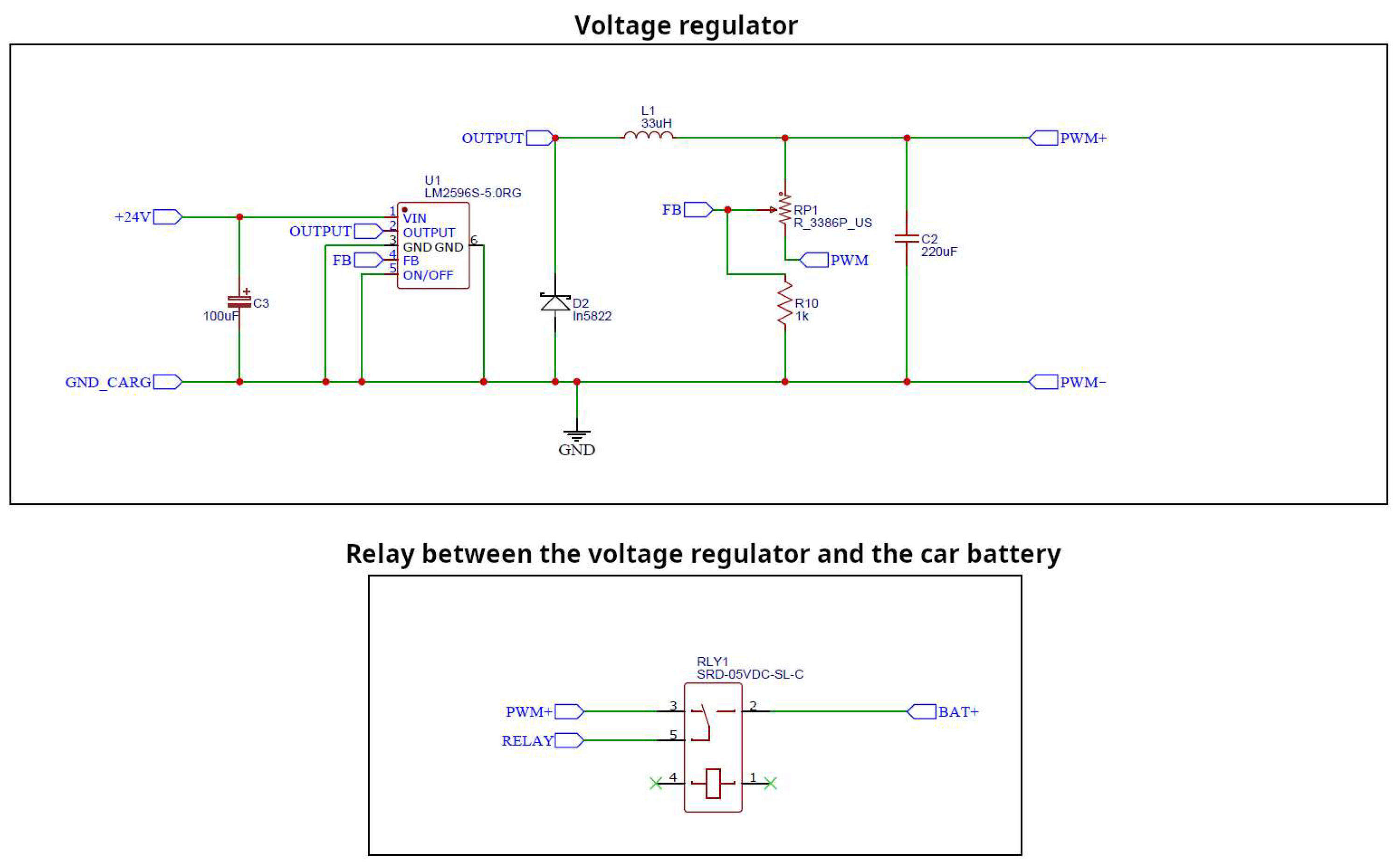
The charging point receives the alternating current delivered through the Mennekes connector. As the charging process operates under modes 2 and 3, an AC/DC power converter is used to convert the delivered alternating current to the direct current. At this point, through the LM2596 power regulator (Elegoo, Inc., Shenzhen, China) illustrated in
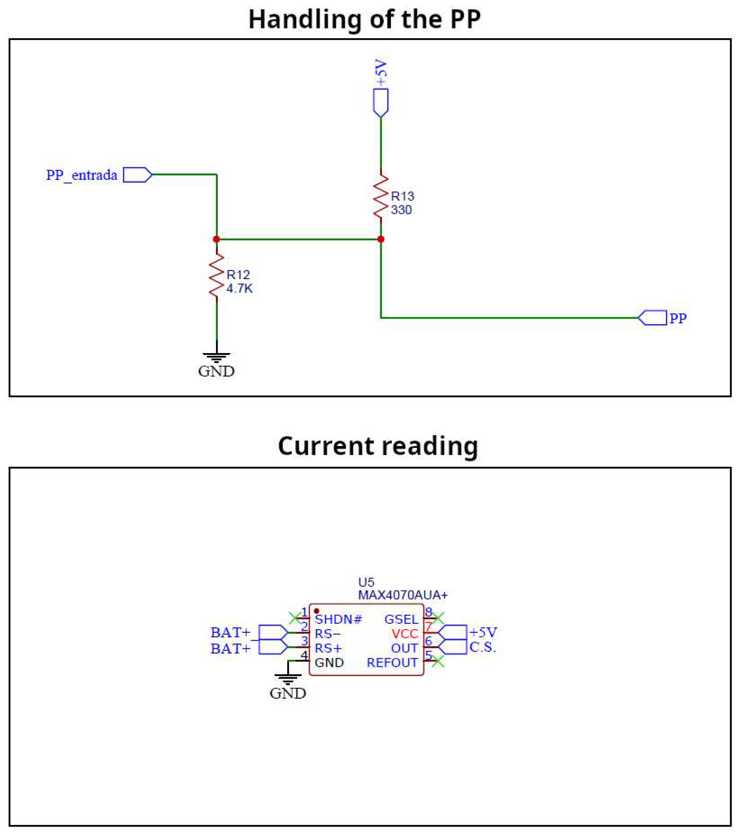
Figure 2a, the direct current obtained from the conversion stage is subsequently regulated using pulse-width modulation (PWM) to deliver a precise voltage level to each charging phase. The LM2596 power regulator facilitates this process by offering an adjustable output between 1.25 and 30 V DC, compatible with input voltages ranging from 4.5 to 35 V DC, and capable of handling currents up to 3 A. Therefore, a 3A fuse has been installed as an overcurrent protection system. In addition, a MAX471 current sensor (Elegoo, Inc., Shenzhen, China) has been used, as shown in
Figure 2b. This sensor offers high-precision voltage and current measurement capabilities, enabling real-time monitoring across various circuit types. It is particularly well-suited for accurate control of the battery charging, with a measurement range spanning from 3 to 36 V and −3 to 3 A, making it responsible for assessing the charging current delivered to the battery. At the same time, the voltage divider measures the voltage in the battery and the charge. An amperimeter has also been used to monitor the current in the battery. A PWM output signal regulates the current going to the battery, while the relay shuts down the charging process when required.
A DC/Arduino power regulator has also been incorporated to supply power to the Arduino board directly from the battery, enabling autonomous operation of the system. The experimental setup also includes a 12 V lead-acid battery, which is the battery that simulates the proposed internal EV charger learning module. It is important to note that this low-voltage battery has been chosen for security reasons, since it is intended for educational use with students. In addition, the setup includes a voltage divider, the LM2596 regulator used to supply power to the Arduino, and a protoboard designated for mounting the required resistors and transistors. Finally, the LCD display shows all the data available from the charging station. All the components used are listed in
Table 1.
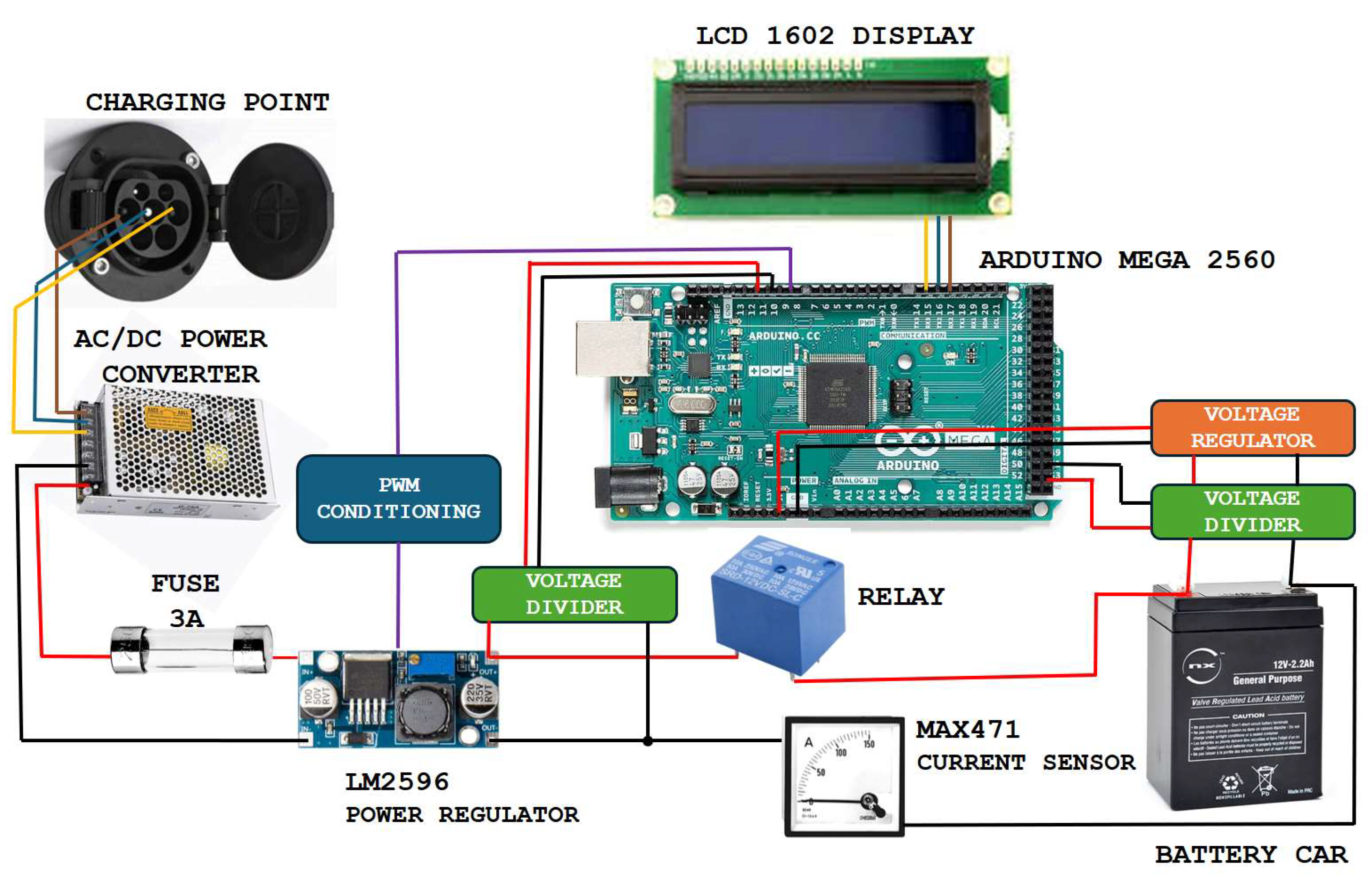
The scheme presented in
Figure 3 shows all the components utilized in the experimental setup and all the connections.
3. Charging Process
This section details the control process carried out with the Arduino Mega 2560 controller board. The charging method chosen regulates the charging voltage dynamically based on the battery’s state. The implemented code defines variables for PWM control, relay states, menu options, and voltage readings, utilizing an LCD display to show charging status and system messages. It reads voltage and current from the battery and PWM circuit via analog pins and implements a connection sequence to detect and validate the vehicle’s presence. PWM modulation is used to regulate the charging voltage based on the battery state, while MENU logic manages multiple charge states, including charging, standby, and disconnection. The system reads the proximity pilot (PP) signal to determine connection status and uses PWM and duty cycle calculations to set charge current limits. Safety checks prevent overcharging and voltage mismatches, with a relay system enabling or disabling charging based on conditions. If the voltage difference between PWM and the battery exceeds a threshold, charging is stopped, and the parameters are dynamically adjusted based on battery voltage. Once charging is complete, the system disconnects the vehicle, and a reconnect function allows charging to resume if the vehicle is reconnected.
After defining all variables within the code, the system was structured to operate in three distinct states: connection, standby, and charging, each of which is explained in detail in the subsequent subsections.
3.1. Connection
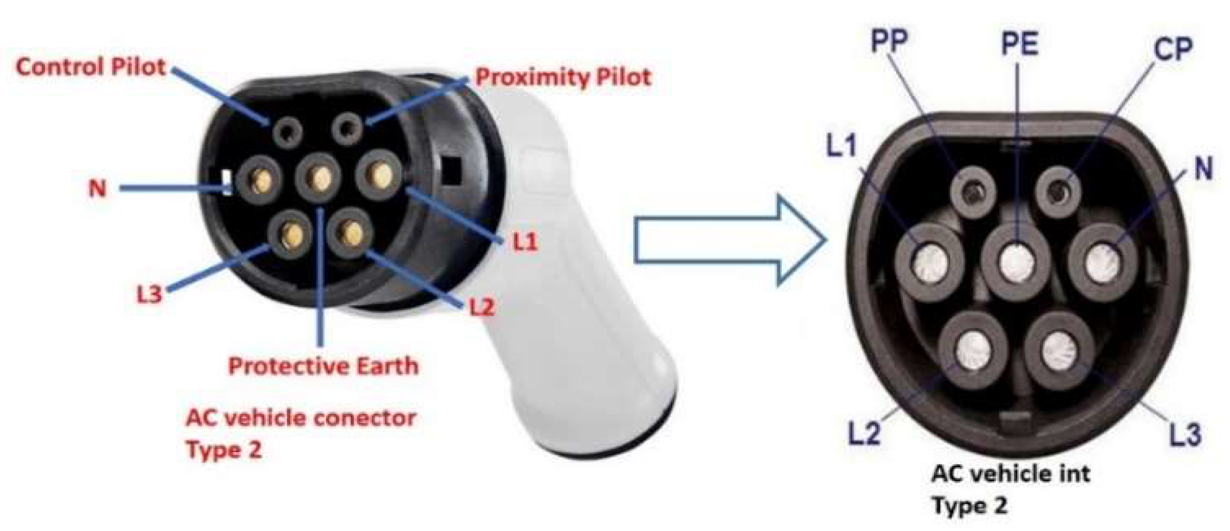
The connection phase begins with the EV in standby mode, awaiting linkage to the charging station. In the current work, a Mennekes connector, also known as the Type 2 connector, has been used since it became the European standard for charging EVs. This connector has a seven-pin configuration, as illustrated in
Figure 4, allowing for both single-phase and three-phase AC charging. The proximity pilot (PP), which communicates the presence of the cable and its current-carrying capacity, is used to carry out the connection.
The PP terminal is utilized to determine if the EV is disconnected from the charging station. A signal below 4.25 V indicates that the EV is connected. When this occurs, the vehicle transmits a high-level pulse to the charging station, which influences the CP signal. The CP manages the charging process by communicating between the vehicle and the charging point. If this condition continues, the EV sends a command to the charging station to engage both contactors by transmitting a high-level pulse corresponding to states A (connection) and B (standby), while simultaneously lowering the CP signal.
3.2. Pulse-Width Modulation (PWM)
Once the charging point is activated to deliver power, the electrical current flows through an AC/DC power converter upon entering the vehicle, as the battery requires DC for charging. From this point, it passes to the LM2596 power regulator, where the process of adjusting the battery charging voltage begins, which is controlled by a PWM voltage. The PWM control board consists of a printed circuit board with two resistors and a capacitor, as shown in
Figure 5. These components regulate the PWM signal that comes out of the controller, Arduino MEGA, and goes to the LM2596 power regulator. In this way, a clean, noise-free pulse is achieved, which in turn has voltage levels appropriate to the type of signal. The pulse value is regulated internally in the Arduino. In this case, according to the battery voltage, the PWM value is calculated. This value has a range of 0–255 which would be a range of 0 to 5 V.
A contactor is positioned between the LM2596 voltage regulator and the battery on the positive terminal, as the negative terminals share a common connection. Its activation depends on specific conditions being met. To protect both the battery and the LM2596 regulator from potential damage or overload, their voltages are monitored through a voltage divider. Based on the measured battery voltage, the PWM signal is adjusted in accordance with Equation (1). This expression is derived through an interpolation obtained from a series of 150 values for the PWM and its corresponding voltage. The points obtained yield a linear relation that allows for the derivation of Equation (1). When the voltage levels are equalized, the contactor closes, initiating the charging process.
where U
bat represents the battery voltage.
3.3. Charging
Regarding the charging process, it should be emphasized that charging the battery at high current values, particularly when it is near full charge or deeply discharged, can significantly shorten its lifespan. For this reason, it is essential to implement a modulation process during recharging. Through this process, the battery is charged up to its maximum capacity to achieve the highest possible charging speed, while always considering the battery’s lifespan. In the experimental setup performed in the current work, once the contactors are closed, the voltage on both sides becomes equal, leading to zero current flow between the LM2596 power regulator and the 12 V battery. Consequently, since the battery may require different charging conditions depending on its voltage level, the process has been divided into six distinct stages.
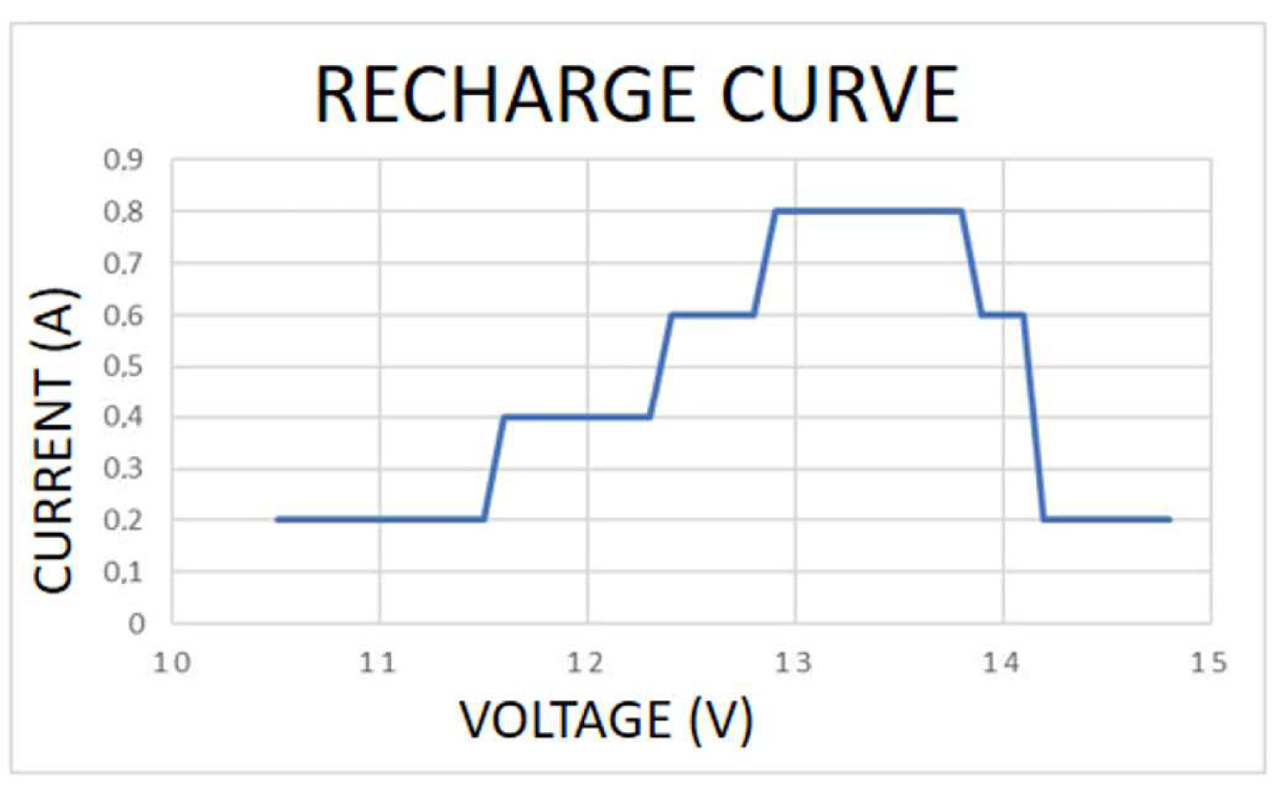
Initially, a recharge test has been performed on a discharged lead-acid battery for assessing its performance and to ensure that it can deliver its rated capacity without significant degradation. This initial test allows evaluating charging system efficiency, confirming that the charger properly follows the bulk, absorption, and floating phases while applying the correct voltage and current. The current applied based on the battery’s voltage, representing the EVs charging profile, is illustrated in
Figure 6. The charging process has three areas. The first one occurs when the battery voltage is low, requiring a low current to protect the cells. In this step, the battery quickly increases its voltage until it reaches its nominal value. Then, once the nominal voltage is reached, the battery’s ability to handle a higher current allows for an increase in current. Finally, the current will decrease until the battery is fully charged. It is important to note that due to the requirements of the batteries, the current curves are not constant in order to prolong their lifespan. Thus, the charger determines the stage based on the battery voltage and, consequently, the applicable current. The stage that best withstands high currents is the one closest to the nominal voltage of the battery, while voltages either above or below this nominal voltage require lower current values. When the battery reaches its maximum value, 14.8 V in this case, the charging process is terminated. The contactor is then opened and the user is informed that the EV can be safely disconnected. It is important to note that the current does not drop to zero due to the vehicle’s residual consumption to avoid draining the main battery.
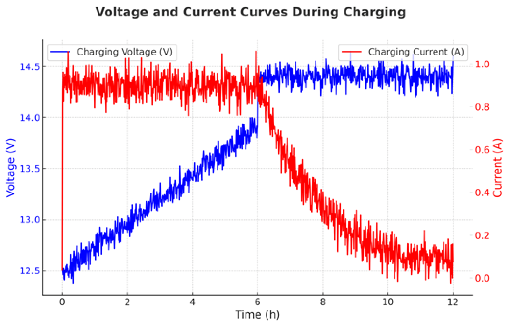
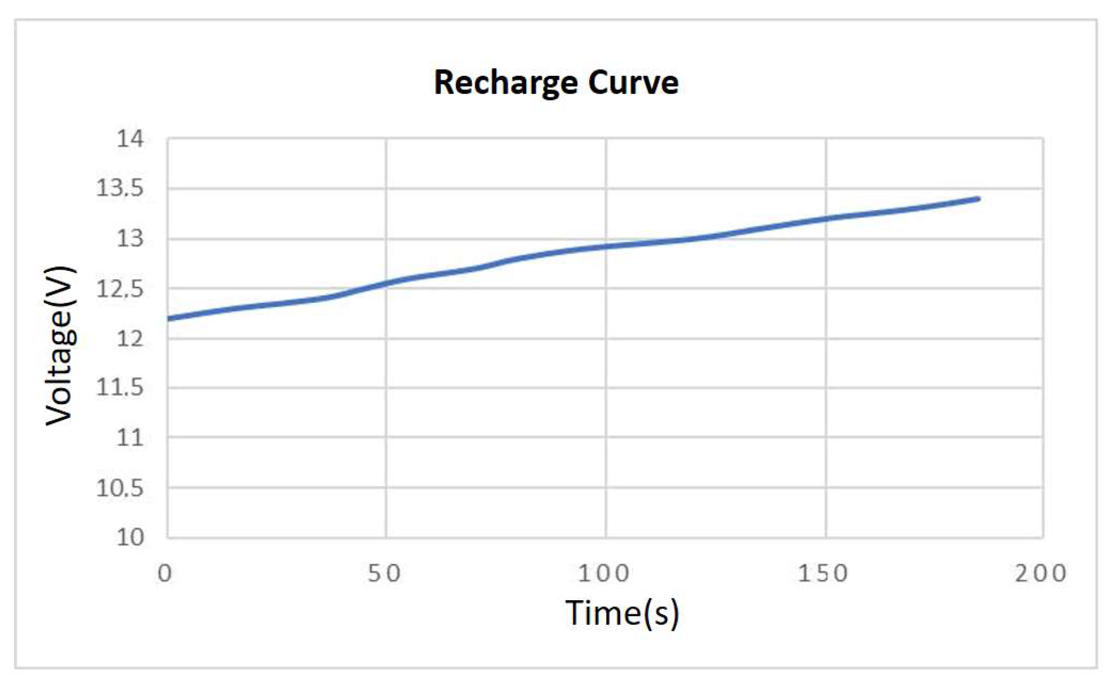
A second recharge test has been carried out with a battery in an optimal state. In this case, the 12 V lead-acid battery charging profile follows a structured process with distinct stages, as shown in
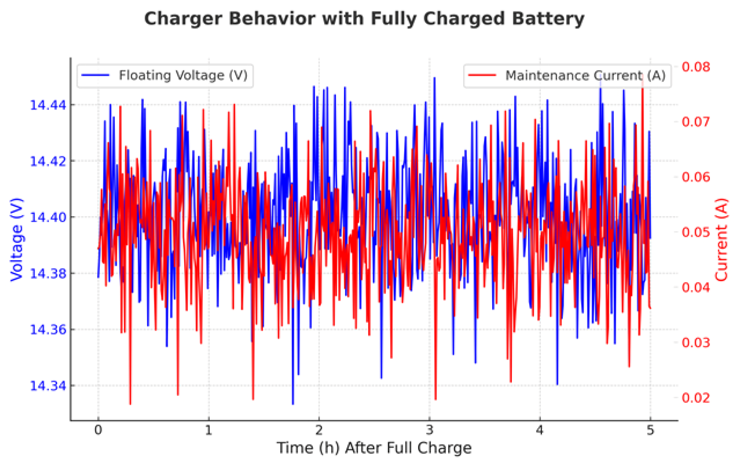
Figure 7. In the Voltage–Time curve, the bulk charge phase shows a rapid voltage increase from 12 to 14.4 V approximately, followed by the absorption charge phase where the voltage remains constant at around 14.4 V, while the current gradually decreases. Finally, in the float charge phase, the voltage stabilizes at around 14.4 V to maintain battery health, as illustrated in
Figure 8. In the Current–Time curve, during bulk charge, the current remains high (~0.9 A) and constant, then progressively decreases in the absorption phase, and finally drops to a low maintenance level (~0.05 A) in float charge to compensate for self-discharge. It can be noted how, at low voltages, the current is at its peak, but as the voltages increases toward 14.4 V, the current declines. Once the battery reaches float charge, the current stabilizes at a minimum level, ensuring efficient energy management while preventing overcharging.
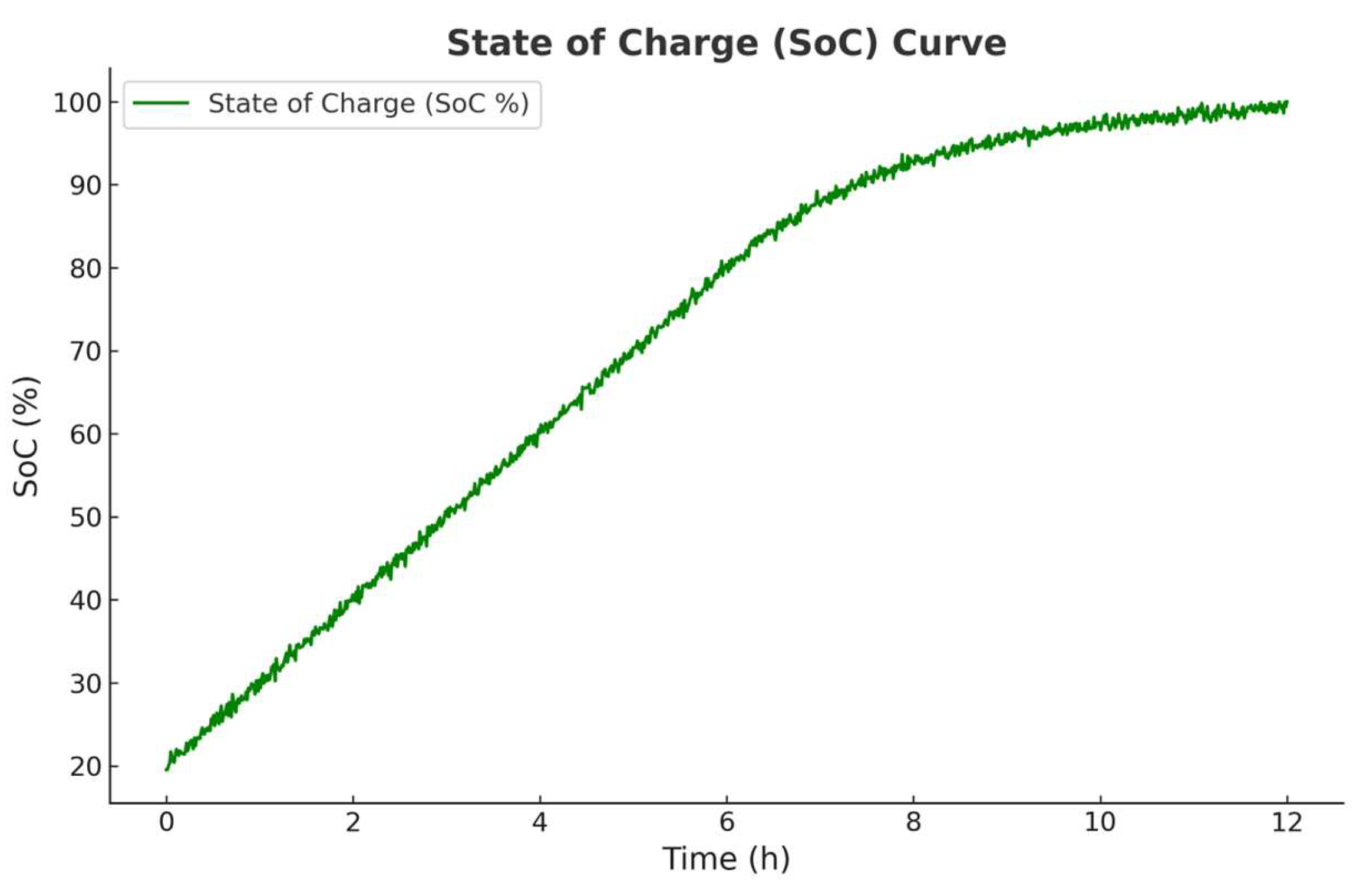
Figure 9 shows the SoC estimation curve obtained, calculated by integrating the charging current over time, as described in Equation (2).
where SoC(t) represents the battery state of charge at time t, SoC(t − 1) the battery initial state of charge, I
charge is the charge current, C
battery indicates the battery capacity in Ah, and t is the time interval in hours.
3.4. Safety Measures
In order to guarantee a secure charging process, multiple safety mechanisms have been integrated into the code. One such measure ensures that if the vehicle is disconnected from the charging station, the charging operation is immediately halted. Moreover, if the voltage disparity between the DC/DC converter and the battery becomes too large, the charging process is halted to prevent the current from surpassing the 3 A threshold. In addition, a fuse is added at the input of the LM2596 converter to protect the system against current spikes.
3.5. Summary of the Charging Process
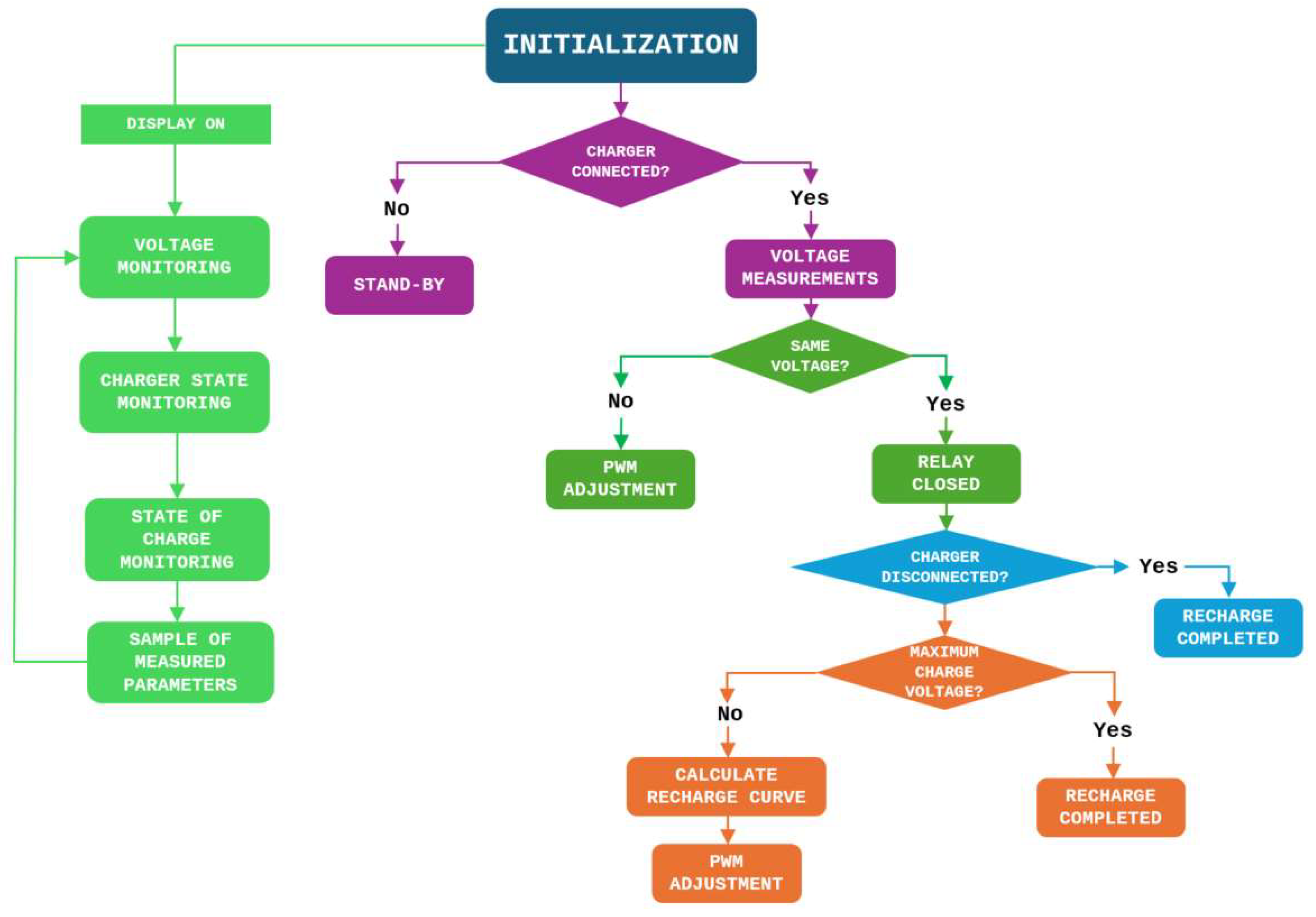
The diagram represented in
Figure 10 shows the whole operation of the internal charger control. This structured approach ensures a controlled and safe charging process of a battery system, ensuring secure and efficient battery charging while monitoring key parameters such as voltage, state of charge, and charger connection status. The process begins with an initialization state, where the system sets up parameters and shows relevant charging information. Then, it collects a sample of measured parameters to evaluate battery conditions. A key decision point checks if the charger is connected. If not, the system enters into stand-by state, waiting for a connection. If the charger is connected, it proceeds to take voltage measurements, where the system verifies whether the battery voltage matches the expected values. If the voltage differs, the PWM adjustment is triggered to regulate the charging voltage. If the voltage is correct, the relay is closed, allowing power to flow into the battery. With the relay closed, the system continuously monitors whether the charger becomes disconnected. If the charger is removed at any stage, the process stops and the recharge is considered completed. If the connection state remains, the system checks whether the battery has reached its maximum charge voltage. If the battery is fully charged, the recharge is considered completed. Otherwise, the system calculates the recharge curve, further PWM adjustments are made, and continues charging until full capacity is reached. Summarizing, the charging process involves the next steps:
Monitoring battery voltage and charge state continuously.
Adjusting PWM dynamically to optimize the charging process.
Implementing safety checks to prevent overcharging.
Handling disconnection scenarios, ensuring that charging stops when necessary.
Automatically completing the recharge cycle when the battery reaches full charge.
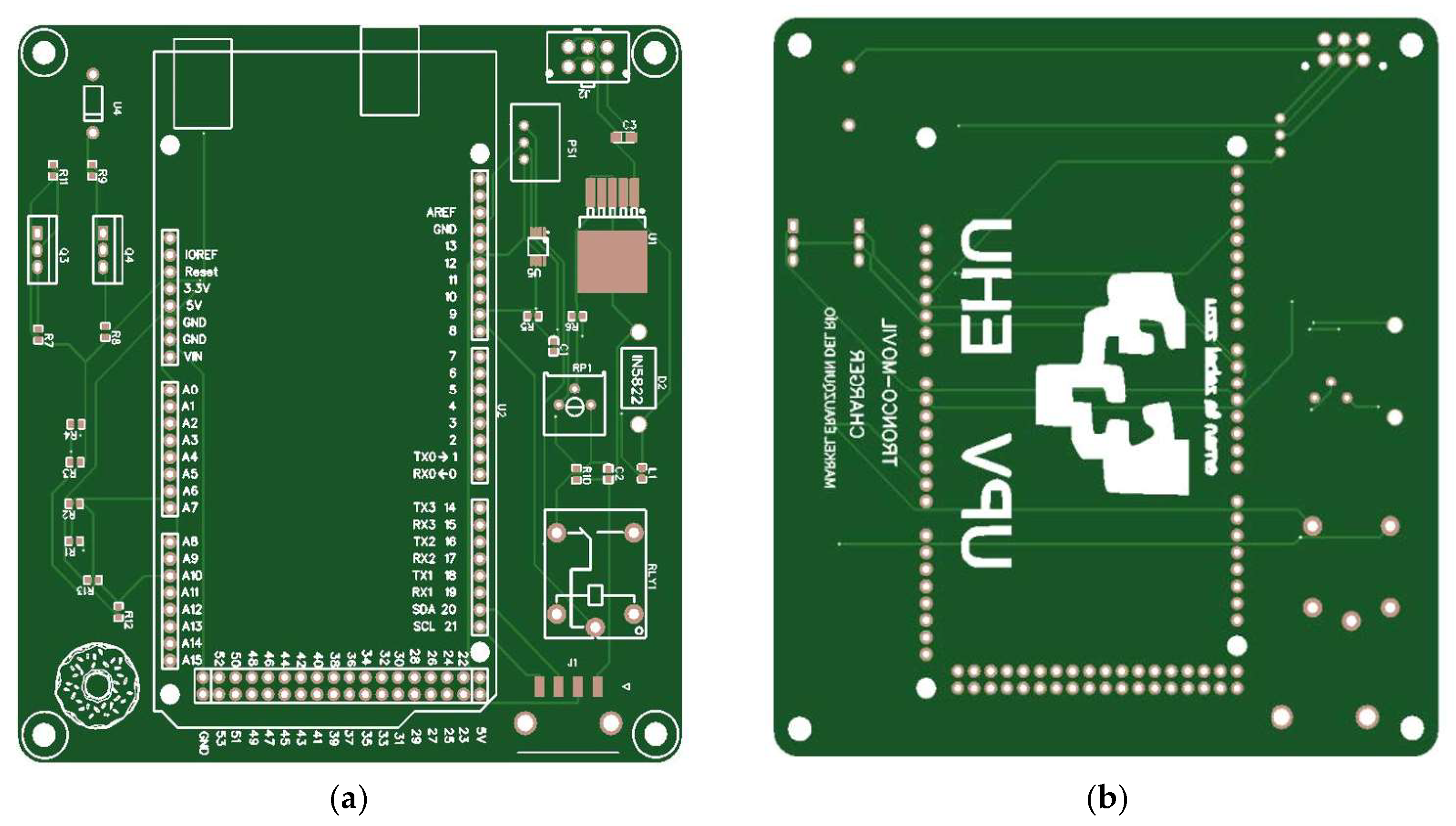
5. Limitations and Improvement Proposal
Despite the vehicle’s internal charger performing well and functioning effectively with the charging station, numerous limitations have been noted in the execution of the installation. For instance, due to security limitations, only a 12 V has been used for testing. Additionally, the wiring used could be improved to ensure good connections. With the aim of overcoming the limitations identified in the current study, the proposal is to develop a printed circuit board (PCB) for making all connections and to use SMD repair techniques, see
Figure 12. This ensures the reliability of the connections and the proper sequence of the installation.
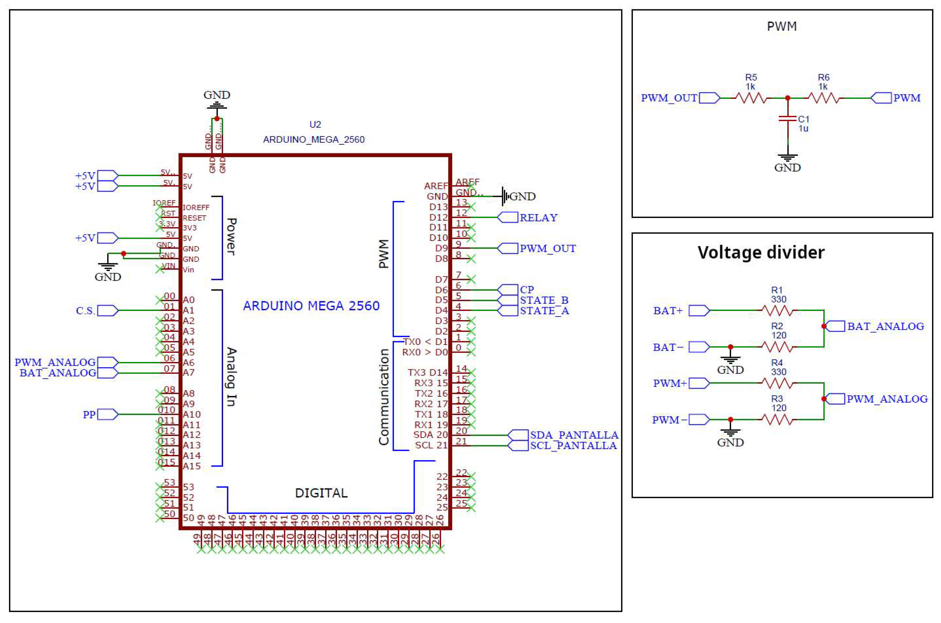
Figure 13 illustrates the pins used for connecting the controller to the different components of the charger, as well as the voltage measurement of the charger and battery.
In
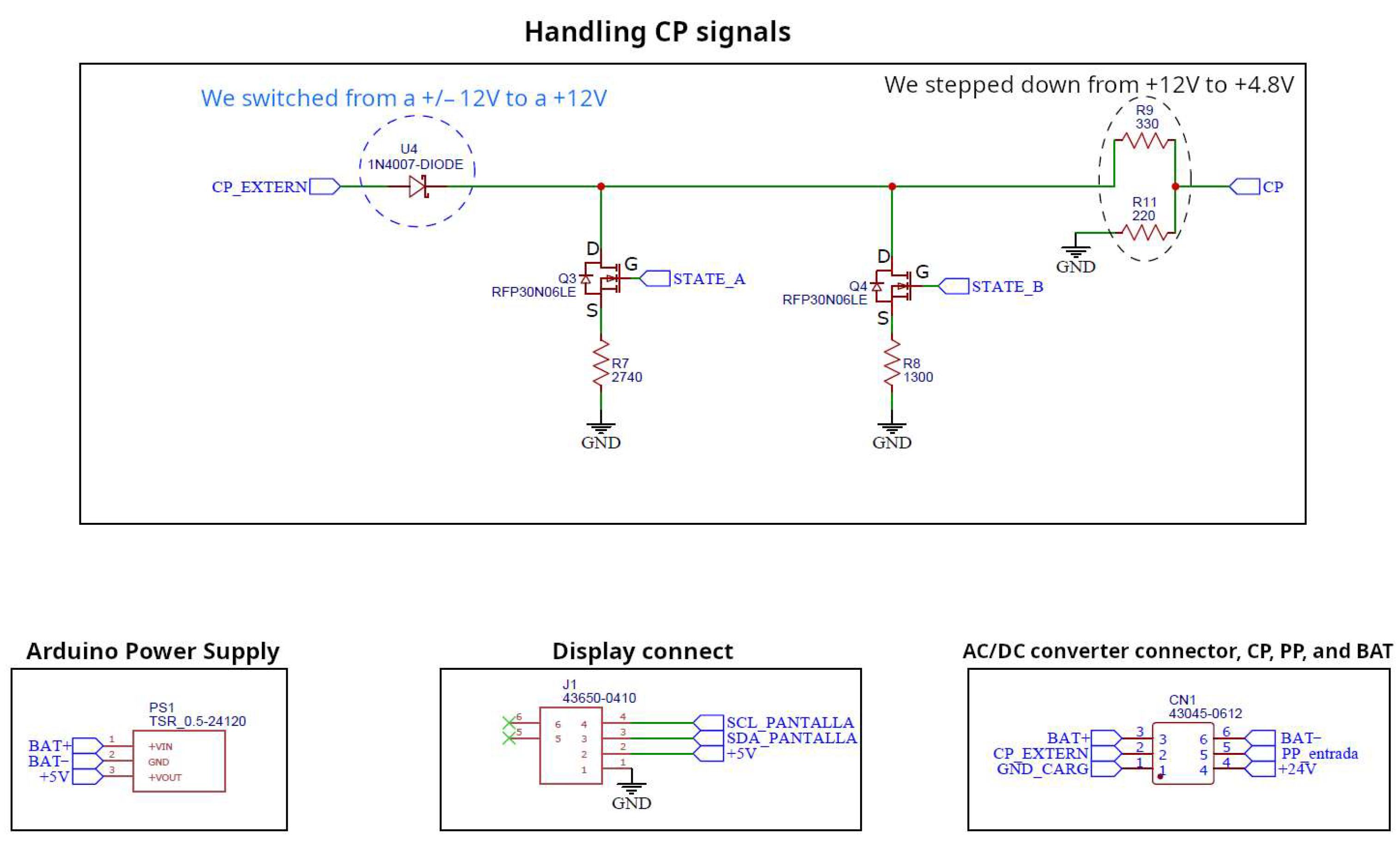
Figure 14, the connectors required by the board to connect the auxiliary devices of the charger can be seen. Additionally, there is a signal conditioning circuit for the CP signals to obtain logical values within the operating range of the Arduino.
Figure 15 shows the voltage variation system for the battery power supply, along with the relay that allows charging when the appropriate conditions are met.
In
Figure 16, the integrated charging current measurement sensor is shown, along with the signal conditioning circuit for the PP signals to obtain logical values within the operating range of the Arduino.
On the other hand, the Arduino modules used for testing are suitable, but for a successful project, all existing modules must be modified to operate with greater precision and wider margins.
Table 2 lists the solutions that can be implemented to modify the modules. The LM317 is a voltage regulator that, at a lower price than the LM2596, allows for a wider voltage range (1.2 to 37 V) and a current output of 1.5 A. This provides greater adaptability to different batteries, along with a wider operating range. The HO 100-P-0100 is a current sensor that, despite being more expensive than the one currently used, offers greater accuracy and a wider measurement range that the MAX471 does not achieve. The TSR 0.5-24120 is an isolated DC/DC converter that allows for the power supply of all control systems with a single component in a very compact package.
The main contribution of this study is to demonstrate the possibility of controlling an on-board charger using low-cost materials.
Table 3 details an estimated cost of all the components used to develop the proposed on-board charger.
For an academic environment, the internal charger proposed in this work offers two main advantages over a commercial one. Firstly, it provides greater safety for the students by operating with a 12 V battery instead of a 400 V one. This result in a significantly lower working power; however, it offers a training platform solution without the additional cost associated with a commercial charger. The total cost of the experimental on-board charger developed in the current work is significantly lower than the cost of commercial on-board charger replacements, which typically range around 1200 € and 2000 € in a standard vehicle. This much lower price than the commercial ones offers more opportunities to the academic institutions to integrate the study and operation of this type of chargers into their training practices. In addition, it offers greater adjustability to each vehicle and the ability to monitor the entire process in real-time.
6. Conclusions
The growing adoption of EVs and the development of supporting charging infrastructure are becoming increasingly critical. Specifically, low-power charging stations intended for installation along public streets and in large commercial parking areas have gained notable relevance. The main motivation of this study is to develop a cost-effective and efficient on-board charging system for electric vehicles (EVs) using low-cost materials while ensuring safe, controlled, and optimized charging. As the adoption of EVs increases, the need for affordable and scalable charging solutions becomes crucial, especially for users and academic environments where high-cost commercial chargers are impractical. The current study presents an on-board electric vehicle (EV) charger using low-cost materials, reducing hardware expenses without compromising performance. It implements a smart charging strategy with real-time monitoring and safety mechanisms, ensuring controlled charging. This study demonstrates that smart charging for EVs can be achieved using low-cost materials while maintaining efficiency and safety. Moreover, the developed on-board charger costs significantly less (~94.82 €) than commercial alternatives (ranging 1200 € to 2000 €). Therefore, the developed system provides an affordable alternative to commercial chargers and serves as a valuable educational tool. This research offers a scalable and cost-effective solution for on-board EV charging, proving that low-cost components can effectively manage and optimize battery-charging processes.
Numerous automotive manufacturers continue to experience considerable difficulties in incorporating these systems into their electric vehicles, often facing persistent charging-related challenges. A notable case is the collaboration between the Volkswagen Group and the Chinese company Geely to leverage its technological solutions. As such, undertaking a project of this kind is particularly valuable, as it enables in-depth exploration of areas such as programming, electronics, and electrical systems.
Although the internal charger was programmed, installed, and tested, several issues were found during the assembly and verification process that must be discussed.
Firstly, inaccuracies were found in the initial voltage measurement when the meter contained in the MAX471 module was used. This lack of precision was corrected by switching to a voltage divider. However, even though this correction improved the accuracy, the use of a DC/DC converter to power the Arduino caused these measurements to become erratic once more.
Secondly, the current measurement has been quite problematic due to the lack of repeated calibration in the MAX471 sensor. Consequently, future improvement proposals will explore alternative methods to enhance this current measurement.
Finally, there were issues with the PWM control during initial calibration. However, once it is calibrated properly, its control has been precise.
Even though all these issues have been resolved, addressing these challenges encountered during testing would be beneficial for enhancing the project.


 ,
, 


