Abstract
Icing on transmission lines poses a serious threat to the power grid. Existing de-icing solutions have limitations in short-distance distribution networks with multiple branches. We propose a method that utilizes a flexible grounding device to adjust the zero-sequence reactive current in the distribution network, enabling de-icing of lines without power interruption. Simulation and experimental results validate the feasibility and effectiveness of the proposed method and control scheme. The method can accurately regulate the de-icing current to achieve de-icing under various conditions, with the actual de-icing current deviating from the set value by less than 0.3%. During de-icing, the line voltage on the load side remains essentially stable, with an error of less than 0.5%, ensuring that the normal supply voltage of the distribution network is not affected, and the entire network load does not require a power outage. The de-icing device interacts only with reactive power in the distribution network, saving capacity for the DC voltage stabilizing power supply and demonstrating good economic efficiency.
1. Introduction
Modern society has increased requirements for the safe and reliable operation of the power grid. However, frequent weather-related disasters have posed serious threats to the safe operation of the power grid [1]. In the current extreme weather encountered by the power grid, snow and ice have caused the most serious consequences, bringing huge losses to the power grid [2]. Transmission and distribution lines, as a major component of the power grid, are widely distributed across various regions, with some lines passing through high-altitude areas prone to icing, making icing an unavoidable issue for transmission and distribution lines [3]. Icing on the line can cause insulator flashovers and conductor oscillation in mild cases, while severe cases may lead to conductor breakage and pole and tower collapses [4,5,6,7], resulting in widespread paralysis of the power grid and posing significant challenges to its operation [8].
Scientific research institutes around the world have carried out significant research on power grid ice-melting technology, which can be divided into mechanical de-icing and thermal ice-melting methods. Mechanical de-icing is inefficient and has safety risks, so the thermal melting method is being promoted and applied in the power grid [9,10]. The basic principle is to apply a transmission current that exceeds the normal current density in the line, causing the ice layer on the line to melt due to heating [11], typically using either alternating current or direct current. The DC ice-melting method features uniform heating and high efficiency during the ice-melting process. However, it is necessary to cut off the load during the DC de-icing process. When applied to the distribution network, due to the existence of a large number of distribution transformers and transformers in the distribution network, it still requires complex switching operations to shut down ice-covered lines, which affects the normal power supply during peak electricity demand in extreme weather. AC ice melting can be further divided into power-frequency short-circuit AC ice melting, high-frequency ice melting, and load transfer ice melting [12,13,14,15]. The load transfer ice-melting method has relatively high requirements for the structure and operation mode of the power grid. The high-frequency excitation power supply in the high-frequency ice-melting method is difficult to obtain, and there are problems such as excessive reactive power compensation and electromagnetic interference. Therefore, it is difficult to apply widely in the distribution network [16,17]. The AC short-circuit ice-melting method needs to be used in cooperation with a reactive power compensator due to its low power factor, and its output voltage is difficult to adjust continuously [18].
It can be seen that all existing ice-melting technologies require power outage during ice melting, and there are obvious limitations in complex distribution network scenarios, which seriously restricts the reliable operation and maintenance of distribution network during extreme ice disasters. It is important to study ice-melting technologies suitable for distribution lines. Zhou et al. [19] propose a method of melting ice on ice-covered wires by using single-phase ground fault current, which can be implemented without interrupting the power supply and reduce the impact on the power load. However, the range of ice-melting current in this scheme is limited, and the lines that can be melted are limited. When the climatic conditions are harsh, the distance of the iced line is long, and the wire diameter is large, the ice-melting current provided by the scheme cannot meet the actual ice-melting demand. At the same time, the impedance value of the adjustable impedance needs to be set before the ice melting starts, and the ice-melting current in the ice-melting process cannot be flexibly adjusted.
In order to make up for the above shortcomings, this paper innovatively combines the characteristics of single-phase grounding faults in ungrounded neutral distribution networks with the adjustment advantages of flexible grounding devices. We introduce a neutral point through a flexible grounding device to flexibly regulate the zero-sequence reactive current of the distribution network through power electronic equipment, which can accurately regulate the ice-melting current. At the same time, it reduces the dependence on large-capacity DC regulated power supplies, saves equipment costs and space, provides an economical and efficient solution for engineering applications, and is of great significance for ensuring power supply and promoting social development.
The rest of this paper is organized as follows. Section 2 designs an efficient non-stop ice-melting system suitable for the distribution network based on the flexible grounding device. Section 3 explores the optimal control strategy for regulating the zero-sequence reactive current to ensure the ice-melting effect. In Section 4, we verify the ice-melting effect of the proposed method and its ability to maintain the voltage symmetry of the distribution network and the continuity of power supply. Section 5 discusses the simulation and experimental results. Finally, we conclude this paper in Section 6.
2. Topology and Principle of Ice-Melting Scheme for Distribution Network Based on Flexible Grounding Device
Most of the medium-voltage distribution networks of 3~66 kV in China adopt the operation mode of ungrounded neutral point or neutral point grounded by arc suppression winding. After a single-phase grounding fault occurs, the line voltage is still symmetrical, so it will not adversely affect the continuity of power supply of the power system, and the power system can continue to operate for 1~2 h. The time required for ice melting in each phase of the line is generally less than 1 h, which provides us with time conditions for ice melting by using single-phase ground faults. A single-phase ground fault in the distribution network will cause the phase voltage of the distribution network to be asymmetrical, and then the sum of the currents flowing through the capacitor to the ground will not be zero. This current flows from the point of failure into the line, causing the current to increase in the line. This provides us with the current conditions for ice melting using a single-phase ground fault. The schematic diagram of the uninterrupted ice-melting scheme of the distribution network based on the improved flexible grounding device is shown in Figure 1. In Figure 1, represents the output current of the melting device, denotes the ground capacitance current, and indicates the ground fault current.
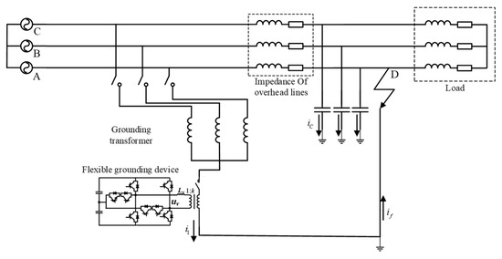
Figure 1.
Schematic diagram of ice-melting system based on T-type 3-level flexible grounding device.
The first end of the icing line is connected to the grounding transformer, and the end of the icing line is grounded with a single-phase short circuit. During the ice melting period, a neutral point is artificially introduced by a grounding transformer, which is connected with the end of the icing line through the ground to form a zero-sequence current loop, so that the current flowing through the icing line is increased to achieve thermal ice melting. For the load side, it is generally a triangle or ungrounded star solution, and zero-sequence current cannot pass through. Therefore, the scheme can ensure the continuity of power supply to the load during ice melting and avoid the influence of power failure associated with traditional ice-melting schemes on economy and society.
Specifically, the phase of the output current is set to lag behind the phase of the neutral point voltage by 90° so that the output current is externally capacitive to ground. The output current of the T-type three-level converter is adjusted to increase the total current flowing through the icing circuit to the critical ice-melting circuit. The current injected into the grid is capacitive reactive current, so there is no active power interaction between the T-type three-level converter and the grid. During the ice-melting process, the voltage of the capacitor on the DC side can be basically stable, so there is no need for a large-capacity DC regulated power supply, which saves the cost and space occupied by the ice-melting device. This allows us to integrate the grounding transformer and converter into a movable ice-melting unit. The entire process of ice melting is shown in Figure 2.
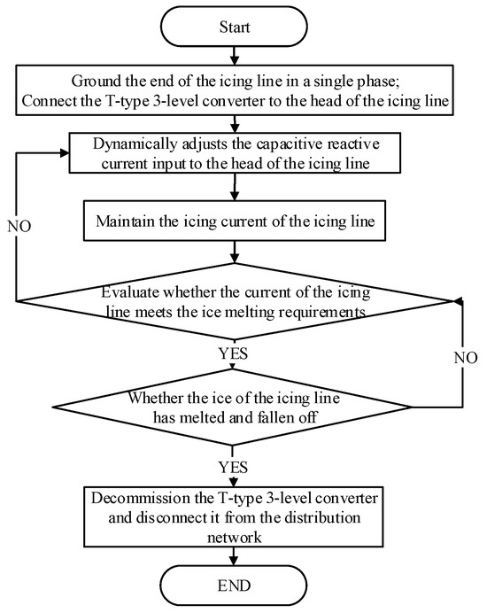
Figure 2.
Flow chart of ice-melting scheme under the access of flexible grounding device.
3. The Strategy for Flexible Control of Zero-Sequence Reactive Melting Ice Current
3.1. The Selection of Reference Current
The vector relationship between the phase voltage and phase current of the line under normal operation conditions is shown in Figure 3. When performing ice melting on phase A of the distribution line, the artificial single-phase ground fault point is set at the end of phase A of the ice-melting line. At this time, the short-circuit point forms a loop with the ground, and the ground fault current flows from the ground to the line. Figure 4 shows the vector relationship between the current of ice melting, the current of the load and the current of the ground fault under the condition of ground fault ice melting,
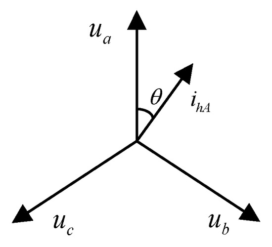
Figure 3.
Vector diagram of voltage and current during normal operation.
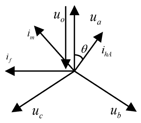
Figure 4.
Vector diagram of voltage and current in the event of a single-phase ground fault.
In this, Ua, Ub, and Uc are the phase voltages, is the ground fault current, is the load current of the single phase of the line, and is the power factor angle of the line.
When the ice-melting device is not connected, the ground fault current is entirely provided by the capacitive current to the ground . At this time, the phase of the ground fault current lags behind the zero-sequence voltage by 90°, that is, it leads the power supply voltage of the ground fault phase by 90°. When the ice-melting device is connected, as shown in Figure 1, the ground fault current is provided by both the capacitive current to the ground and the output current of the device , that is:
To satisfy the ice melting requirements, the ice-melting current of the line needs to reach at least the critical ice-melting current. The ice-melting current includes the load current and the ground fault current, as can be seen from Figure 4; when the flow current in the line is equal to the critical ice-melting current, Equation (2) can be obtained:
The value of the ground fault current required to achieve a critical value for the ice-melting current can be obtained as follows:
According to the magnitude of the critical ice-melting current , the magnitude of the load current of phase A , the power factor angle , and the magnitude of the ground fault current, the amplitude reference value of the output current of the T-type three-level converter at the beginning of the ice-covered line can be calculated.
where is the phase voltage of the power supply; is the angle frequency of the power grid; C is the value of the capacitance of the distribution network to the ground.
Therefore, the governing equation for the input current of the T-type 3-level converter at the head of the icing line is as follows:
where is the proportionality coefficient of the current controller; is the integration coefficient of the current controller; is the modulated voltage signal output by the controller; is the neutral voltage.
If the actual ice-melting current cannot meet the specific rapid ice melting occasion, the input current of the icing line can be increased in time to fit in the actual allowable ice melting time, and the ice covering on the wire can be cleared within the specified time. The proposed ice-melting method does not need to remove the load, so the current flowing in the icing wire is the superposition of the zero-sequence reactive current and the positive-sequence load current, which can further accelerate the speed.
3.2. The Selection of Modulation Strategy
In multi-level converter circuits, the phenomenon of DC voltage imbalance is quite common. This will cause uneven pressure on the power switch devices, resulting in distortion of the current on the grid and an increase in harmonics. When the voltages of the DC-side capacitors are severely unbalanced, for example, if the voltage across the upper capacitor is the DC-side voltage and the voltage across the lower capacitor is 0, then the turn-off voltage for a single switching device is the total DC voltage. If the device’s voltage withstand capability is insufficient, it may be damaged. In order to solve the problem of voltage imbalance on the DC side of multi-level circuits, the single-phase SVPWM modulation method is adopted in this paper, and the voltage equalization algorithm is designed on the basis of it. Using this solution, the output voltage harmonic content is lower, the DC bus voltage utilization is higher (increased by about 15%), the switching loss is more balanced, and the dynamic response is faster.
Depending on the magnitude of the absolute value of the resulting output voltage, the switching vectors are divided into three categories: When the absolute value of the voltage at the output of the converter is equal to , the working states at this time are 1 and 5, which are called large vectors, and are defined as V8 and V9; when the absolute value of the voltage at the output of the converter is equal to , the working states at this time are 2 and 4, which are called small vectors, and are defined as V4, V5, V6, and V7; when the absolute value of the voltage at the output of the converter is equal to 0, the working state at this time is 3, which is called zero vector, and is defined as V7, V1, V2, V3. According to the effect, the vector diagram of spatial modulation can be obtained by mapping each vector to the spatial coordinate system, as shown in Figure 5.
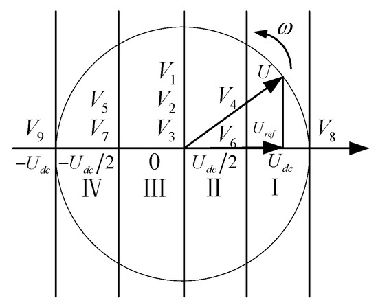
Figure 5.
Space vector diagram based on SVPWM.
In the diagram, represents the voltage on the direct current side, stands for the reference voltage vector, is the magnitude, ω is the angular velocity, and φ is the initial phase.
When a small vector is applied, one capacitor charges while the other discharges, causing the voltage at the midpoint to rise or fall. When a large vector is applied, both capacitors charge and discharge simultaneously, and the midpoint voltage remains unchanged. When a zero vector is applied, neither capacitor is connected to the grid, and the midpoint voltage remains unchanged. In summary, large and zero vectors do not cause voltage imbalance, while paired small vectors result in voltage deviation across the capacitors. Once we know the direction of the voltage offset at the midpoint and the direction of the grid-side current, we can select the redundant small vectors that need to be applied. The selection of small vectors in each sector can be carried out according to the process diagram in Figure 6.
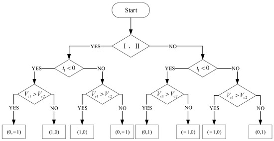
Figure 6.
Voltage balancing algorithm based on small vectors.
In the diagram, and represent the voltage across the DC-side capacitors. The ultimate goal of selecting small vectors is to cause the midpoint voltage to change in the opposite direction, achieving balanced voltages across the upper and lower capacitors.
4. Simulation and Verification of Flexible Control Strategy
To verify the feasibility and effectiveness of the method for de-icing distribution lines based on zero-sequence reactive current regulation, a 10 kV distribution network simulation model was constructed using MATLAB/Simulink R2021b software, as shown in Figure 7.
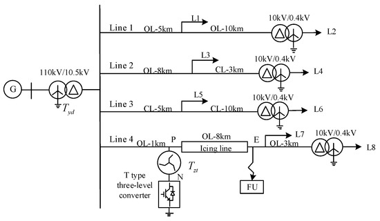
Figure 7.
Diagram of the simulation model of the distribution network.
The icing occurred in a 10 km overhead line segment of feeder 3, with a load rated at 0.4 kV voltage level. The distribution network simulation model includes power source G, 110 kV transformer , grounding transformer , four feeders, loads Ln (n = 1~8), fault occurrence unit FU, etc. The power grid is in a three-phase symmetrical state when not covered by ice. The loads in the system are all at a voltage level of 0.4 kV. According to the ice-melting method proposed earlier, it is necessary to connect the grounding transformer to the beginning of the ice-covered line and to connect the fault occurrence unit FU to the end of the ice-covered line. We assume that icing occurs in feeder 4. The icing line is an overhead line with a length of 8 km, a voltage level of 10 kV, and a model of LGJ-120. At this time, the temperature is minus 5 degrees, and the wind speed is 5 m/s. Therefore, the grounding transformer is connected at the starting point P of the icing line and leads to the neutral point N of the distribution network, with the T-type 3-level device connected to point N and the fault occurrence unit FU connected to the end point E of the icing line.
Power supply G uses a three-phase source from the Simulink library components. We set the RMS value of the line voltage to 110 kV, the coupling group to Yg, and the initial phase angle of phase A to 0°. The transformer is represented by a three-phase transformer (Two Windings) in the library components, with its connection mode set to Yg/D11 and a capacity of 20 MVA. The ground transformer is represented as a ground transformer (Grounding Transformer) in the library components, with a capacity of 5 MVA and a rated voltage of 10.5 kV. There are two types of lines: Cable Line (CL) and Overhead Line (OL); CL-y km means that the length of the cable line is y km, and OL-x km means that the length of the overhead line is x km. The line model is represented by the Three-Phase PI Section Line in the library components. The positive-sequence and zero-sequence resistances are denoted as and , the positive-sequence and zero-sequence capacitances are denoted as and , and the positive-sequence and zero-sequence inductances are denoted as and , respectively. The specific line parameters can be found in Table 1. There are eight sets of loads, which are represented by the Three-Phase Series RLC Load in the library element, and the individual load parameters are shown in Table 2. The FU selects the Three-Phase Fault module of the library component.

Table 1.
The voltages of the upper and lower capacitors on the DC side.
Table 2.
Load parameters.
4.1. Simulation Verification of the Control Strategy of Voltage Equalization
It is known from the previous analysis that the prerequisite for the normal operation of the ice-melting device based on zero-sequence reactive current is the normal operation of the single-phase T-type three-level inverter. Therefore, the functionality of the voltage equalization control strategy will be verified through simulation.
In order to verify the correctness of the single-phase equalizing SVPWM modulation algorithm, a simulation model of single-phase T-type three-level PWM converter was built in MATLAB/Simulink. Table 3 shows the simulation parameters.
Table 3.
Simulation parameters of a single-phase T-type three-level.
The upper and lower capacitor voltages at the initial moment of simulation are set to 60 V and 40 V, and the simulation results are shown in Figure 8.
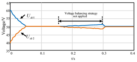
Figure 8.
The voltages of the upper and lower capacitors on the DC side.
After the device is started up, the total voltage on the DC side quickly stabilizes to the set value of 100 V, and the voltages of the upper and lower capacitors are also stabilized at about 0.05 s at 50 V. In 0.15 s, the equalization control is removed, that is, the selection of redundant small vectors in SVPWM is turned off, so the upper and lower capacitor voltages begin to deviate. At 0.3 s, the SVPWM small vector coordination strategy is re-enabled, so the upper and lower capacitor voltages quickly return to balance. It can be seen that the single-phase pressure equalization SVPWM modulation method proposed in this paper is feasible and rapid.
It can be seen that the voltage of the capacitor on the DC side of the device is controlled during the ice-melting process. It can avoid the uneven voltage of the power switching device due to the unbalanced voltage on the DC side, so as to avoid the distortion of the current output of the device.
4.2. Simulation Verification of the Output Ice-Melting Current
Taking the distribution network line in the mountainous area of northern Guangdong as an example, the range of its wire diameter is LGJ-95~LGJ-240, and Table 4 shows the critical ice-melting current of lines with different wire diameters under several common meteorological conditions, from which it can be seen that the critical ice-melting current ranges from 228.63 A to 562.72 A.
Table 4.
A table of the critical ice-melting current values corresponding to different wire diameters [20].
As can be seen from Table 4, the critical ice-melting current required by the LGJ-120 line is 348.29 A when the air temperature is minus 5 degrees Celsius and the wind speed is 5 m/s.
Under normal operation and when melting ice (the de-icing current is set to 360 A), the three-phase current waveform flowing through the icing section of the line is shown in Figure 9.
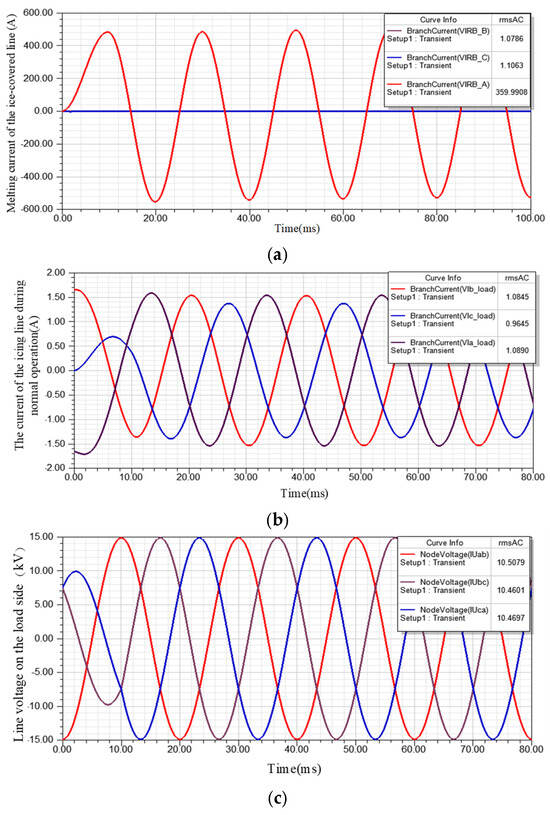
Figure 9.
Current and the load side line voltage in the iced line during normal operation and the melting process. (a) Current in the iced line during normal operation. (b) Current in the iced line during melting operation. (c) The load side line voltage.
From the simulation results, it can be seen that when the ice-melting device is not connected to the system, the three-phase icing line flows through the positive-sequence load current and the three-phase current is about 1 A. When the de-icing device is connected to the beginning of the ice-covered line and the A phase end is grounded, the current of phase A reaches 359.9908 A, which is basically consistent with the design value of 360 A, meeting the de-icing requirements of the line. The currents of phases B and C remain at the normal working current of 1 A.
It can be seen from Figure 9c that during the ice-melting process, the three-phase voltage on the load side of the line remains symmetrical, and the line voltage does not change significantly. For a 10 kV distribution network line, the allowable voltage deviation on the end-user side is −10% to +5%. Therefore, when the ice-melting device is put into operation for ice-melting work, the line does not need to be powered off and can continue to supply power to users. This verifies the feasibility and effectiveness of the proposed non-power-off ice-melting scheme.
To further analyze, the sequence components of the de-icing current of phase A are extracted. Figure 10 shows the extraction results of the current of phase A.
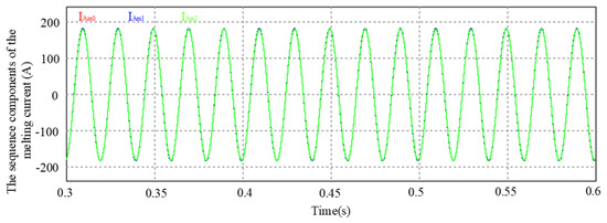
Figure 10.
The sequence components of the melting current of phase A.
It can be seen from Figure 10 that the directions of the positive-sequence, negative-sequence, and zero-sequence current components of phase A are the same and their magnitudes are equal, with effective values of approximately 120 A. The current value of phase A is about three times that of the zero-sequence current, reaching the de-icing condition. For phases B and C, their positive- and negative-sequence components differ from phase A by 120 degrees and 240 degrees, respectively. Therefore, when the sequence components are superimposed, they partially cancel each other out, resulting in a smaller sum of the sequence components in phases B and C, which does not meet the de-icing condition. Thus, it is necessary to de-ice the three-phase line sequentially.
Figure 11 shows the current waveform flowing through the three-phase winding on the primary side of the grounding transformer.
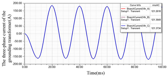
Figure 11.
Current on the primary side of the grounding transformer.
It can be seen from Figure 11 that during the de-icing operation, the zero-sequence current of the grounding transformer for each phase is approximately 121 A, which is equal to the zero-sequence component of the de-icing current for phase A shown in Figure 10. Ignoring the load current, the de-icing current of the phase A line is almost entirely injected through the grounding transformer by the T-type three-level device, and thus the magnitude of the de-icing current in the ice-covered line can be altered by changing the output current of the T-type three-level device.
When the time is 0.05 s, the end of the ice-covered line is carried out a single-phase grounding short circuit, and when it is 0.15 s, the ice-melting device is connected to the first end of the ice-covered line. During this period, the output current and neutral point voltage of the de-icing device at the beginning of the icing line are shown in Figure 12.
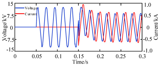
Figure 12.
The output current of the device at the beginning of the ice-covered line and the voltage of the grid neutral point.
As can be seen from Figure 12, after 0.05 s, the neutral voltage rises from 0 to the phase voltage due to the single-phase grounding fault of the line. Then, 0.15 s later, with the connection of the ice-melting device, the device injects current into the neutral point; at this time, the neutral point voltage fell a little but basically remained stable, and the phase difference between the output current of the de-icing device at the beginning of the icing line and the neutral point voltage of the grid is close to 90°. Therefore, the output current of the device is primarily capacitive reactive current, and the interaction with the active power of the grid is nearly zero.
In order to verify the ice melting conditions under different working conditions, such as changing the temperature, wind speed, ice thickness, etc., we set the ice-melting currents to 395 A and 300 A, respectively, and the ice-melting currents and voltage at this time are shown in Figure 13.
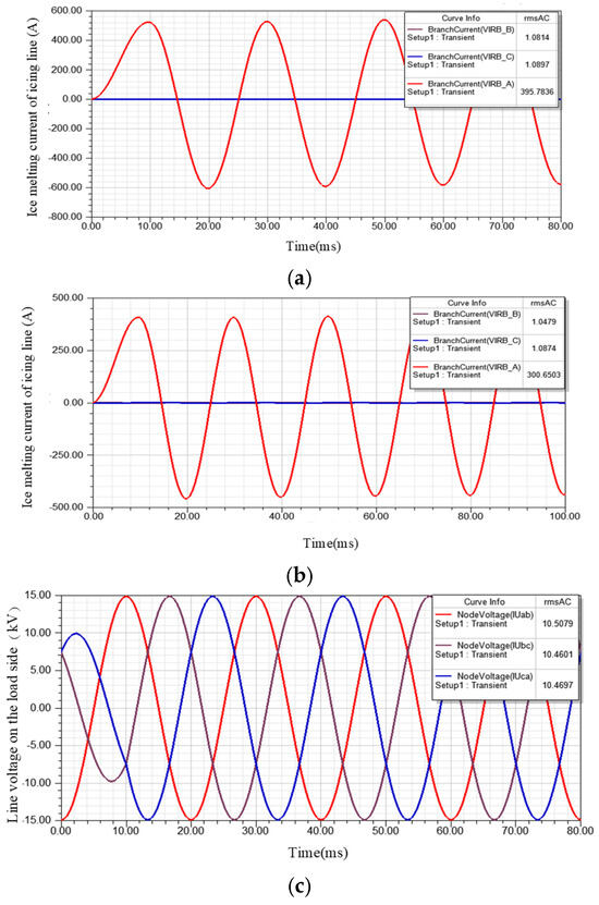
Figure 13.
Ice-melting current and the load side line voltage in the icing line (when the ice-melting current is set to 395 A and 300 A). (a) Current (the ice-melting current is set to 395 A). (b) Current (the ice-melting current is set to 300 A). (c) The load side line voltage.
As can be seen from Figure 13, when the ice-melting current is set to 395 A, the current corresponding to the ice-melting phase is 395.7836 A, and the error is 0.198%. When the ice-melting current is set to 300 A, the current corresponding to the ice-melting phase is 300.6503 A, and the error is 0.217%. The current in the non-ice-melting phase is essentially unchanged and is consistent with normal operation. Because the simulation test is based on the ice-melting of the A-phase transmission line after the A phase is connected to the ground, and the effective current value of the B phase and the C phase is only about 1 A, which is very small compared with the A phase, so it is roughly identical. As can be seen from Figure 13c, the line voltage on the load side remains virtually unchanged.
The winter load of the non-icing section at the front end of the pilot line is generally about 4000 kVA; in order to verify the influence of the change of load on the ice-melting current, the output current of the device is still set to be 360 A, and whether the value of the ice-melting current changes greatly when the load changes and the simulation results are shown in Figure 14 below.
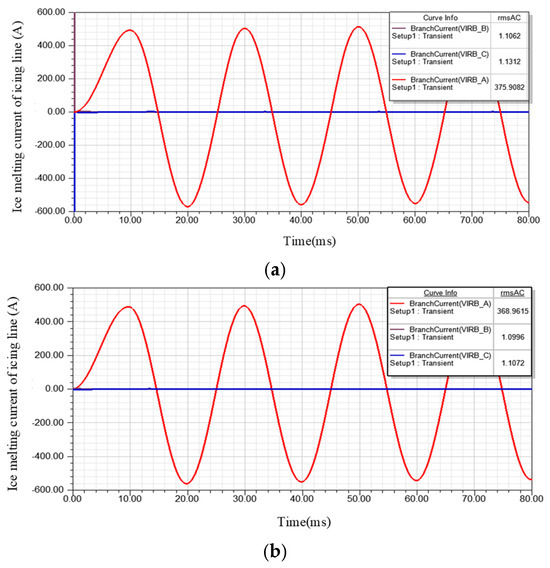
Figure 14.
Icing melting current of icing line (5000 kVA and 3000 kVA). (a) 5000 kVA. (b) 3000 kVA.
When the load of the non-icing section is increased to 5000 kVA, the ice-melting current changes to 375.9 A; when the load of the non-icing section is reduced to 3000 kVA, the ice-melting current changes to 368.9 A; when the load is 4000 kVA, the ice-melting current changes to 360.0 A. From the above analysis, it can be seen that the voltage drop of the front-end line will change when the load of the non-icing section increases or decreases, but the amount of change is within a reasonable range and has little impact on the ice-melting current, so the influence of the load of the non-icing section can be ignored when designing the ice-melting current of the ice-melting device.
In order to further verify the feasibility of the on-line ice melting idea designed in this paper, the three-phase current imbalance on the load side is simulated, and if the above pilot line simulation parameters are still used as the ice-melting outer circuit, only the three-phase impedance on the load side is changed, so that the load impedance of phase A and C is 28 + j18Ω, and the load impedance of phase B is 14 + j14Ω. The ice-melting current of the A-phase line is still selected and the output current of the ice-melting device is set to 360 A. Figure 15 shows the load side three-phase current and the load side line voltage during the normal operation and the melting operation of the line due to the asymmetry of the three-phase current under the condition of different three-phase impedances on the load side.
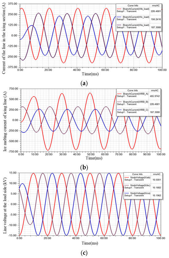
Figure 15.
Current and the load side line voltage during normal operation and the melting operation of the icing line (when the load is unbalanced in three phases). (a) Current during normal operation. (b) Current during the melting operation. (c) The load side line voltage.
As can be seen from Figure 15, the line current of phase B and C is still consistent with that of normal operation: the current of phase B is still about 226 A, the line current of phase C is still about 187 A, and the current of phase A is increased to 465 A due to the superposition of the zero-sequence ice-melting current component, and its value far exceeds the minimum current required for ice melting due to the large line load current.
As can be seen from Figure 15c, when the three-phase is unbalanced, the load sideline voltage of the icing section still maintains three-phase symmetry, so the on-line ice-melting idea proposed in this paper is also applicable to the working condition of three-phase load asymmetry.
Generally speaking, the ground conductivity of the line is very small, and the ground resistance is very large, so the active current formed by the ground resistance is very small, and as such, the ground resistance of the line is not considered when calculating the ice-melting current. When single-phase ground fault occurs, the main external factor affecting the ice-melting current is the ground capacitance current. In order to fully verify the influence of line capacitance to ground current on the size of the ice-melting current, simulation of whether there is capacitance to ground is carried out under two working conditions. When the impedance of the adjustable reactor connected to the ice-melting circuit is 12.67 Ω, Figure 16 shows the simulation results without and with the consideration of the capacitance to the ground.
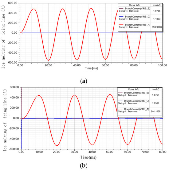
Figure 16.
Current during the melting operation of the icing line (when considering an unpaired capacitance). (a) When capacitance to ground is not considered (Zadj = 12.67 Ω). (b) When capacitance to ground is considered.
When the influence on the ground capacitance is not considered, the ice-melting current of the phase A line is 360 A. As can be seen from the simulation results in Figure 16, when the influence on the ground capacitance current is considered, after the end of phase A is connected to the zero-sequence reactance integrated device, the current of the phase A line is 344.1 A, and the current of the B and C phases is still about 1.1 A, the same line current as normal operation.
Since the ice-melting current of the distribution network is mainly controlled by the ice-melting device at the head of the iced line, the ice-melting current required is different for different ice melting scenarios. Therefore, it is required that the control of the ice-melting device can adapt to the adjustment needs of different currents, that is, the device should have good performance under different equivalent ground capacitances. The key influencing factors of the performance and stable operation of the device are reflected in the ability to regulate the equivalent capacitance current to the ground.
A Bode plot illustrating the control operation of the de-icing device under different equivalent ground capacitance conditions is provided as shown in Figure 17.
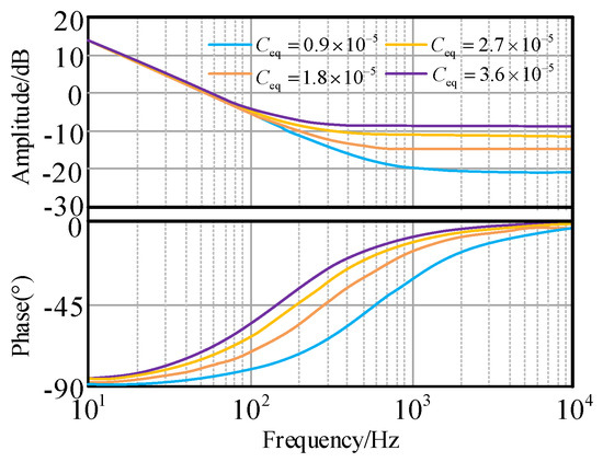
Figure 17.
Control Bode diagrams of ice-melting device.
As can be seen from Figure 17, the stability margin and phase margin meet the requirements, the current output of the device can be quickly adjusted and increased according to demand, and the ice-melting device has good control stability and robustness, which can adapt to the ice-melting current demand in different situations and will not be affected by relevant parameters.
Therefore, the simulation under the above different working conditions verifies that the designed on-line ice-melting device can realize the ice melting operation of different lines under different conditions and different ice melting requirements and has no impact on the voltage and current on the load side during the ice-melting period, so that the normal power supply to the user can be realized during the ice-melting period and the ice melting can be achieved without interruption.
4.3. High-Current Test
In order to prove the function and correctness of the device in non-power melting ice, the high current test was carried out from 15–20 January 2025. The LGJ-95 line in the mountainous area of northern Guangdong was selected as the test object. The ice section line is located on the top of the mountain at an altitude of 400 m, the end load of the ice section is only 20 KVA, and the line current of the ice section is only about 1 A when the line is working normally, while the minimum ice-melting current of the line of LGJ-95 is more than 264 A, and the ice-melting current is almost all provided by the ice-melting device.
The front end of the online ice-melting test device is composed of a ground transformer, a T-type three-level converter, a three-phase line isolation switch, and a three-phase circuit breaker. Figure 18 shows photos of the on-site ice-melting device.
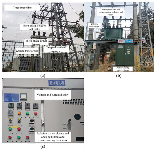
Figure 18.
On-site diagram of on-line ice-melting device. (a) Device head. (b) Device end. (c) Inside the deicing switch cabinet.
Target melting currents of 290 A, 300 A, and 310 A were selected to ensure the safety of the test. When closing, the three-phase line isolation switch should be closed first, so that the three-phase line is connected to the ground transformer, then the corresponding isolation tool switch, and finally the three-phase circuit breaker. During the test, the voltage and current data displayed in the deicing switch cabinet were recorded, as shown in Table 5.
Table 5.
The results of the pilot line experiment.
From the comparative analysis of the results, it can be seen that the current of the ice-melting phase (phase A) increases to meet the demand of ice melting, but the current of the other two phases is not much different from that of normal operation. The line voltage on the load side is reduced but basically symmetrical. The results of the experiment are basically consistent with the simulation results above.
5. Discussion
The simulation results indicate that the voltage balancing strategy can maintain the stability of the DC side capacitor voltage during the ice-melting process and support the device to continuously output current normally, which contributes to the realization of ice melting without power interruption. During the ice-melting process, the current of one phase (the phase where a short circuit occurs) reaches the set value for ice-melting current while the currents of the other phases remain normal. Therefore, ice melting can be per-formed on one phase of the line at a time, and after the ice melting is completed, the short-circuited phase is replaced to perform ice melting on the other phase lines. It can be observed from the simulation under different working conditions that when changing parameters such as temperature, wind speed, and ice thickness, the de-icing current can meet expectations, and the load side voltage remains stable. Therefore, this method has a wide range of applicability. The changes in load, the three-phase imbalance of the line, and other factors will not affect the normal operation of ice melting. The ice-melting cur-rent in the line is primarily determined by the output current of the ice-melting device. Therefore, the ice-melting current can be precisely controlled by adjusting the output cur-rent of the device, enabling ice melting without power interruption, and this method has good accuracy. During the ice-melting period, the line voltage on the load side is essentially symmetrical, thus allowing for normal power supply to users during the ice-melting period, achieving ice melting without power interruption. This plan has good power sup-ply continuity. There is a 90-degree phase difference between the output current of the de-vice and the neutral point voltage; thus, the device only has reactive interaction with the distribution network, saving the capacity of the DC voltage regulator and reducing the cost of the device.
In addition, although formal melting ice tests have not yet been conducted during the winter’s frozen period, the results of the current elevation tests indicate that the ice-melting device designed in this paper can operate without power interruption while also allowing for flexible adjustment of the ice-melting current to accommodate different melting conditions.
To further analyze the advantages and disadvantages of the proposed de-icing scheme, a comparison was made between several typical direct current and alternating current de-icing devices for distribution networks, as shown in Table 6.
Table 6.
Comparison of different schemes.
According to the analysis results, the method proposed in this article has advantages over direct current melting devices in that it requires fewer components, has lower costs, does not require load shedding during operation, and can continuously provide power services, resulting in high overall economic efficiency. Compared to alternating current melting devices, based on manual grounding, the melting current of the method proposed in this article can be quickly and accurately adjusted according to demand without jeopardizing the safe operation of the distribution network and exhibits good overall performance and efficiency.
6. Conclusions
To address the limitations of existing de-icing technologies that require power outages and demonstrate poor adaptability in complex distribution network scenarios, this study proposes a non-interruptive de-icing method for distribution networks based on flexible grounding devices. By leveraging the zero-sequence reactive current regulation capability of flexible grounding devices, this method enables precise and continuous ice melting without interrupting power supply. Simulation and experimental results have validated the feasibility and effectiveness of the proposed de-icing system. Specifically, the findings demonstrate that the method can control de-icing current errors within 0.3% while maintaining load side voltage fluctuations below ±0.5%. These results confirm that the system achieves precise current control while ensuring grid stability, representing a significant advancement over conventional methods.
The system exhibits robust performance under varying environmental parameters (temperature, wind speed, ice thickness) and diverse operating conditions (load variations, load imbalances, different grounding capacitances), demonstrating its strong adaptability. High-current tests further verify the method’s practicality, showing that targeted current adjustments in specific phases achieve the desired de-icing effect while preserving voltage symmetry on the load side.
However, the practical application of this method still faces some engineering challenges, such as ground device capacity optimization, complex branch line cooperative control, device compatibility with more complex network topologies, or the need to coordinate with system protection. Subsequent studies will focus on multi-line collaborative ice melting control strategies and lightweight device design to improve engineering applicability under complex distribution network topologies. The results provide a new technical path for safety anti-icing of distribution networks with both economy and reliability.
Author Contributions
Supervision, Y.Z. and F.Y.; resources, J.X.; data curation, J.W.; writing—original draft preparation, J.X.; writing—review and editing, Y.Z., F.Y. and D.L.; project administration, Y.Z. and X.T. All authors have read and agreed to the published version of the manuscript.
Funding
The research was funded by China Southern Power Grid Co., Ltd. Technology Project-GDKJXM20230615.
Data Availability Statement
Data is unavailable due to privacy or ethical restrictions.
Acknowledgments
We gratefully acknowledge the support of Qingyuan Power Supply Bureau China Southern Power Grid Corporation for providing funding. We also thank Dayi Li for his valuable comments on the manuscript.
Conflicts of Interest
Authors Yabing Zhou, Fang Yang and Xiaoliang Tang were employed by the company Qingyuan Power Supply Bureau China Southern Power Grid Corporation. The remaining authors declare that the research was conducted in the absence of any commercial or financial relationships that could be construed as a potential conflict of interest.
References
- Sun, C.X.; Sima, W.X.; Shu, L.C. Atmospheric Environment and Electrical External Insulation, 1st ed.; China Electric Power Press: Beijing, China, 2002. [Google Scholar]
- Jiang, X.L.; Yi, H. Icing and Protection of Transmission Lines, 1st ed.; China Electric Power Press: Beijing, China, 2002. [Google Scholar]
- Huang, X.; Liu, J.; Cai, W.; Wang, X. Present Research Situation of Icing and Snowing of Overhead Transmission Lines in China and Foreign Countries. Power. Syst Technol. 2008, 27–32. [Google Scholar]
- Tomaszewski, M.; Ruszczak, B.; Michalski, P.; Zator, S. The study of weather conditions favorable to the accretion of icing that pose a threat to transmission power lines. Int. J. Crit. Infrastruct. Prot. 2019, 25, 139–151. [Google Scholar] [CrossRef]
- Hao, Y.; Wang, X.; Liang, W.; Zhang, W.X.; He, J.Q.; Wang, J.X.; Li, H.; Wen, Y.; Mao, X.; Wu, J.R.; et al. Ice types identification and prediction of overhead transmission lines driven by micro-meteorological data of three consecutive days icing. Southern Power Syst. Technol. 2023, 17, 107–116. [Google Scholar]
- Zhang, D.; Liu, J.; Huang, X.; Zhang, Z. Non-contact icing monitoring method for composite insulators based on spatial electric field. Southern Power Syst. Technol. 2021, 15, 99–106. [Google Scholar]
- Li, Y.; Yang, J.; Zheng, W.; Liu, B.; Gao, Z. Conductor galloping distribution map of Liaoning Province developed with specific return period. China Electr. Power 2022, 55, 129–134. [Google Scholar]
- Han, Y.; Su, G.; Yuan, H.; Ma, W. Early-warning model for icing power grid accident based on rough set. J. Tsinghua Univ. (Nat. Sci. Ed.) 2010, 50, 1930–1933. [Google Scholar]
- Wang, C. Research on DC Ice-Melting Technology for Transmission Lines. Master’s Thesis, North China Electric Power University, Beijing, China, 2011. [Google Scholar]
- Wu, S.Y.; Jing, P. Key Technologies of DC Ice-Melting for Transmission Lines; China Electric Power Press: Beijing, China, 2014. [Google Scholar]
- Guizhou Power Grid Co., Ltd. Engineering Application of Key Technologies for Power Grid Anti-Icing; China Electric Power Press: Beijing, China, 2014. [Google Scholar]
- Tang, A.; Yang, Y.; Yang, H.; Song, J.; Qiu, P.; Chen, Q. Research on Topology and Control Method of Uninterrupted Ice Melting Device Based on Non-contact Coupling Power Flow Controller. Proc. CSEE 2023, 43, 8666–8674. [Google Scholar]
- Yan, G.; Wang, J.; Huang, H.; Chen, H.; Li, Y.; Yu, B. Research on the Resonance Mechanism and Suppression Measures of Modular Multilevel DC Ice-Melting Devices. Power Syst. Prot. Control 2022, 50, 180–187. [Google Scholar]
- Cinieri, E.; Fumi, A. Deicing of The Contact Lines of the High-Speed Electric Railways: Deicing Configurations. Experimental Test Results. IEEE Trans. Power Deliv. 2014, 29, 2580–2587. [Google Scholar]
- Kollar, L.E.; Farzaneh, M. Modeling Sudden Ice Shedding From Conductor Bundles. Modeling Sudden Ice Shedding From Conductor Bundles. IEEE Trans. Power Deliv. 2013, 28, 604–611. [Google Scholar]
- Li, Z.H.; Bai, X.M.; Zhou, Z.G.; Hu, Z.J.; Xu, J.; Li, X.J. Prevention Methods and Research Progress of Power-Grid Ice Accretion. Power Grid Technol. 2008, 32, 7–13. [Google Scholar]
- Yuan, X.L.; Zhou, Y.S.; Wang, Y.A.; Xiong, Q.; Wang, X.J.; Ma, X.H.; Dai, Z. Analysis and Calculation of High-frequency Excitation Ice-melting for Transmission Lines Based on Electromagnetic-Thermal Coupling Field. Power Syst. Prot. Control 2019, 47, 103–109. [Google Scholar]
- Zou, L. Research on AC Ice-melting Devices for Transmission Lines in Baishan Area. Master’s Thesis, North China Electric Power University, Beijing, China, 2019; pp. 7–11. [Google Scholar]
- Zhou, Y.; Tang, X.; Hou, Y.; Yang, F.; Wang, H.; Wang, T. Research on on-line ice-melting technology based on zero sequence reactance integrated device. In Proceedings of the 2019 22nd International Conference on Electrical Machines and Systems (ICEMS), Harbin, China, 11–14 August 2019; pp. 1–5. [Google Scholar] [CrossRef]
- Lu, J. Grid Icing Disasters and Prevention Technology, 1st ed.; China Electric Power Press: Beijing, China, 2016; p. 221. [Google Scholar]
- Zhang, Y.K.; Li, B.T.; Li, B.; Wang, T. Ground-fault Location Technology for Extra-high Voltage Transmission Lines during DC De-icing Process. Autom. Electr. Power Syst. 2017, 41, 105–111. [Google Scholar]
- Guo, Y.Q.; Zhou, Y.B.; Xu, J.Z.; Xu, S.K.; Zhao, C.Y.; Fu, C. Control Strategies of DC Ice-melting Equipments for Full-bridge Modular Multilevel Converters. Autom. Electr. Power Syst. 2017, 41, 106–113. [Google Scholar]
- Xu, K.; Ma, X.H.; Rao, C.L.; Chen, P.L.; Liu, J.; Liang, Y.Q. Research and Comparison of DC Deicing Technologies Based on Full Bridge MMC and Thyristor Rectifier. South. Power Syst. Technol. 2020, 14, 45–53. [Google Scholar]
Disclaimer/Publisher’s Note: The statements, opinions and data contained in all publications are solely those of the individual author(s) and contributor(s) and not of MDPI and/or the editor(s). MDPI and/or the editor(s) disclaim responsibility for any injury to people or property resulting from any ideas, methods, instructions or products referred to in the content. |
© 2025 by the authors. Licensee MDPI, Basel, Switzerland. This article is an open access article distributed under the terms and conditions of the Creative Commons Attribution (CC BY) license (https://creativecommons.org/licenses/by/4.0/).