Article

An Investigation into the Insertion of a Solid Mandrel into a Commercial Cylindrical Li-Ion Cell for Improved Thermal Performance

1
WMG, University of Warwick, Coventry CV47AL, UK
2
Boyd Corporation, Unit 12, Wansbeck Business Park, Ashington NE638QW, UK
*
Author to whom correspondence should be addressed.
Energies 2025, 18(7), 1825; https://doi.org/10.3390/en18071825
Submission received: 6 March 2025 / Revised: 27 March 2025 / Accepted: 2 April 2025 / Published: 4 April 2025
(This article belongs to the Section J1: Heat and Mass Transfer)

Abstract

:
Cylindrical Li-ion cells have found utilisation in numerous industries, but they are susceptible to thermal issues, and so they require suitable thermal management. One of the conceptual methods for addressing this issue is the introduction of a metallic mandrel inserted axially through the cell’s central cavity, which has previously been shown to have a thermal benefit through simulation, thermal emulation, and experimentally through bespoke functional test cells. This work has demonstrated the potential ability to modify a commercial LGM50 21700 cell to accept a 2 mm solid metal mandrel whilst maintaining functionality, and then to quantify the thermal behaviour under representative real-world operating conditions. The modification to external geometry is believed to have reduced the effective cooling area, and therefore leads to a temperature increase of 1–5.2 °C on the mandrel cell. The pristine reference cell then underwent the same external geometry modification, which showed no consistent thermal benefit compared to the mandrel cell, which was then validated through simulation. The simulated model evaluated the additional thermal resistances introduced by the modification process and highlighted the potential benefits of using a bespoke cell housing with an integrated mandrel over mandrel insertion. This was more significant under higher current loads, with a 7.2 °C maximum temperature reduction for the bespoke cell housing during a 3 C discharge.

1. Introduction

Cylindrical Li-ion cells are utilised extensively in many applications, including transportation (e.g., electric vehicles and aerospace), grid storage, and consumer electronics [1,2] for their high energy density and relatively low cost [3]. A cylinder, for battery technology, is a common form factor (shape), as it is one of the most efficient ways of maximising the surface area contact of the active material (and hence the cell capacity) in a given volume. This high efficiency winding leads to heat generation and thermal regulation issues in the cell core, which can accelerate degradation [4] and pose safety issues due to the risk of thermal runaway [5], making the inclusion and function of internal safety features, such as pressure burst discs and Current Interrupt Devices (CID), a common addition to cell design. It is widely reported that the composite nature of the active material geometry also creates a difference in the axial and radial thermal conductivities of up to two orders of magnitude (around 0.3 and 30 W/mK, respectively) [6], which leads to thermal gradients forming in both directions, the magnitude of which is directly impacted by system-level thermal management systems and may further amplify cell degradation and safety concerns [7]. These thermal issues are not limited to cylindrical cells, and multiple solutions have been proposed to reduce the maximum temperature and thermal gradients using cell-integrated features, such as external fins [8], as well as heat pipes, both internally [9] and externally [10,11], for pouch and prismatic cell formats. For cylindrical cells, the highest temperature region (hot spot) during operation is in the cell core [12]; therefore, one of the more popular solutions has involved the direct targeting and cooling of the cell core using various methods to more effectively extract the heat out of the cell and to the cooling system.
Sievers et al. [13] simulated a cylindrical cell with a hollow central mandrel through the entire cell length, with the purpose of immersion cooling and directing the coolant flow through the channel, which had a 5–7 °C max temperature reduction. In the study, a second modification involving a 2.88 mm diameter solid copper mandrel through the cell length was also considered, showing an approximate 2 °C max temperature reduction compared to the standard reference cell.
Shah et al. [14] also investigated the use of both a heat pipe and a solid copper mandrel cooling concept, but with a thermally emulated test cell, with a 2 mm diameter mandrel showing a max temperature reduction of 17.5 °C and the 6 mm mandrel showing a 19.8 °C reduction compared to the cell with no added mandrel. Both the solid copper rod and heat pipe were 10 cm in length and protruded from the 65 mm cell top and base, showing little difference in the thermal performance between the two mandrels. Furthermore, it is discussed that the relative cost and complexity of a heat pipe is far greater than a solid rod and, as such, this lack of comparative performance improvement does not justify the use of a heat pipe solution in this case. The impact of 2 mm and 6 mm mandrels on the volumetric energy density and capacity are also discussed, with the 2 mm mandrel causing a 2% reduction in capacity versus a 20% reduction for the 6 mm mandrel, based on the active material volume for a fixed cell size.
Worwood et al. [15] have also developed a simulation model for a cell with an internal heat pipe mandrel and 2 mm heat spreader discs at the top and base of the jelly roll for improved thermal heat extraction. For an 18650 and 32113 cell with 3 mm and 6 mm heat pipe mandrels, respectively, the maximum temperature was reduced by 9.5 °C and 9 °C, with jelly roll axial gradients being reduced by 9.1 °C and 8.8° when compared to a base-cooled cell with no mandrel or heat spreader discs.
Gou et al. [16] have proposed an internal 3 mm diameter heat pipe with a fan-cooled heat sink, coupled with Phase Change Material (PCM) to regulate the cell temperature in an 18650 size, 1300 mAh functional custom cell. Whilst this cell was functional, it had an expanded mandrel that was 6 mm in diameter, and it appeared to not have a top cap and, hence, no safety features or hermetic seal. At 3 C discharge, the hollow mandrel reference cell reached a max temperature of 42.5 °C, whereas the heat pipe and PCM cell reached a max temperature of 33.8 °C. The external thermocouples also demonstrated only a 0.9 °C temperature gradient for the heat pipe cell, as opposed to the 2.2 °C gradient for the base cell. This represents a significant improvement in the thermal performance with the inclusion of the heat pipe and PCM; however, the impact of such a modification on the volumetric and gravimetric energy density are not discussed. This cell, with its expanded mandrel, has approximately a 10% lower capacity compared to standard 18650 cells [17], and a far lower energy density, although the magnitude of this penalty is not able to be quantified.
Anthony et al. [18] have also constructed a 26650 2800 mAh functional cell, with a protruding integrated 2 mm diameter heat pipe. For a 20 A (~8 C) discharge, up to a 20 °C difference in the core temperature is measured between the actively cooled heat pipe end and an inactive insulated heat pipe, lowering to a 10 °C difference when the heat pipe is ambiently cooled. The inactive case also had a 13 °C radial gradient, as opposed to a <1 °C gradient for the actively cooled heat pipe, even dropping just below 0 °C, meaning that the core was cooler than the cell surface. Finally, a comparison is made between only cooling the heat pipe and only cooling the cell exterior, showing an 18 °C radial gradient for cell exterior cooling and, again, a near-zero radial gradient for the heat pipe.
The previous work has all been undertaken on conceptual cells, wherein the internal dimensions, jelly roll size, and architecture of the cell have been simplified by ignoring the internal design and safety features for the benefit of demonstrating a thermal improvement of the inclusion of a solid mandrel; they are not representative of a commercially available cell. The experimental studies with functional cells have also relied on the mandrel protruding significantly from the cell to directly cool the mandrel to achieve a thermal benefit, which would require additional system-level considerations regarding the integration and utilisation of these cells in a real-world application and, hence, would likely not be feasible in a thermal management system.
A number of studies have identified the need for further evaluation of the concept, with a focus on realistic and representative methods of mandrel integration within commercial cell technologies where the additional material, electrical, and architectural issues are considered. The contribution of this work is to produce a functional, modified commercial cell with the integrated solid mandrel, whilst maintaining all other cell features, such as the tabs and safety features.
The objective for this paper is to include the additional material and design considerations with the intent of quantifying how much these thermal performance improvements rely on assumptions and idealised computer simulation models. By modifying a commercial cell that has minimal impact on the function, the realistic benefit of the integration of the solid mandrel may be quantified with greater certainty pertaining to the source of any thermal benefit, and not additional factors in the manufacturing process. The functionality of the cell enables real cell operation through charge–discharge cycling, rather than emulation, which further increases the real-world applicability. This work aims to enable the next stage in the integration of the solid mandrel, and to move forward from unrealistic and idealistic modification proposals.
This paper is structured as follows. Section 2 outlines the design considerations for this work, as highlighted in the review of the literature, alongside details of the modification process of a pristine cell to integrate the solid mandrel. This is followed by the discussion of the experimental test-rig setup and the definition of the test parameters, as well as verification of the functionality and electrochemical characterisation of the experimental cell. Section 3 presents two separate studies with different reference cases, which are as follows: one unmodified (pristine) cell and one cell with an external modification. This is followed by the creation of a simulation model in Section 4, which aims to replicate the experimental modifications and validate the results to better understand the effect these modifications have on the thermal performance of the cell, leading to recommendations for effective utilisation of the mandrel concept. A discussion of the implications of this work and the conclusions are presented in Section 5 and Section 6, respectively.

2. Experimental Method

2.1. Definition of Cell Concept

For this investigation of a solid mandrel integrated into a functional cell, one of two approaches may be taken based on the literature; by adding a standalone solid mandrel into an existing cell (based on emulation and functional cell experimental work) or designing a cell with the mandrel integrated into the cell housing/base at the point of manufacture (based on simulation work). The first approach would be the shortest and most cost-effective solution by using existing modification procedures [19], not requiring the manufacture of a custom-made cell, and is therefore the chosen approach for this proof-of-concept study. The downside to this approach is that the base of the cell would be the modification site and would act as the cooling interface to allow the mandrel to be cooled directly. This means that any protruding modification would reduce the effective surface area for cooling when compared to a bespoke cell design. The custom-made cell approach would address the downside of the modified cooling interface, although it would also incur significant cost and manufacturing challenges that are deemed beyond the scope of this initial investigation. Without loss of generality, an LGM50 21700 cell has been chosen in this study due to its popularity in energy storage and automotive applications, as well as in previous studies using this cell for similar modifications for the purpose of advanced characterisation [19,20].
In order to create a functioning cell with an integrated solid mandrel, considerations such as material compatibility, mandrel size, insertion, and securing techniques are made. For the mandrel material, copper and 304 stainless steel were used, as they are both present in the cell body and are connected to the electrically negative portion of the cell. Copper is used as the anode foil material and stainless steel is commonly used as the housing material, ensuring that solid mandrels will not induce additional chemical reactions in the electrolyte, as opposed to materials such as aluminium. Copper has a comparatively higher thermal conductivity (400 W/mK) than stainless steel (16 W/mK), although both of these are orders of magnitude higher than the electrolyte that would otherwise fill the mandrel void (in the order of 0.6 W/mK) [21].
The mandrel diameter was limited by the 3 mm void in the centre of the jelly roll. The mandrel was manufactured to accommodate this space and to maximise the heat conduction whilst retaining the unmodified jelly roll. The final main consideration is the method of engineering the cell to accept the mandrel without compromising the functionality of the cell or damaging the internal components. Due to the similarity of the modification and the availability of equipment, the method used by Gulsoy et al. [19] was adapted for this work. A detailed description of this process will not be repeated here; however, a brief overview of the pertinent points is provided for completeness. The methodology is based on creating a pilot hole in the negative terminal, with minimal swarf formation and material loss. While forming the hole, a shallow burr inside the cavity is created, where the current collector and the cell container are joined. A thread is created along the burr to achieve a hermetic seal for the cells after insertion of the solid mandrel. This method enables access directly into the hollow mandrel of the cylindrical cell without compromising the electromechanics or integrity of the cell case or its internal components.

2.2. Cell Modification Process

Figure 1 shows an overview of the steps in modifying the cell to accept the solid mandrel. These consist of the following:
(1)
Mandrel fabrication was conducted, which involved cutting the mandrels to 60 mm length and filing down one end of the mandrel to approx. 1 mm in diameter.
(2)
The mandrels were then secured into a hollowed M2.5 screw with epoxy and dried in a vacuum oven at 50 °C for 5 h.
(3)
The mandrel was coated in a thin layer of MG Chemicals 4225 epoxy and dried in a vacuum oven at 60 °C for 7 h to ensure full electrical insulation during insertion and operation of the cell.
(4–5)
The pristine LGM50 cells were subjected to Open Circuit Voltage (OCV) and Reference Performance Tests (RPT) to verify functionality. A full description of this experimental process is provided in Section 2.3.
(6–7)
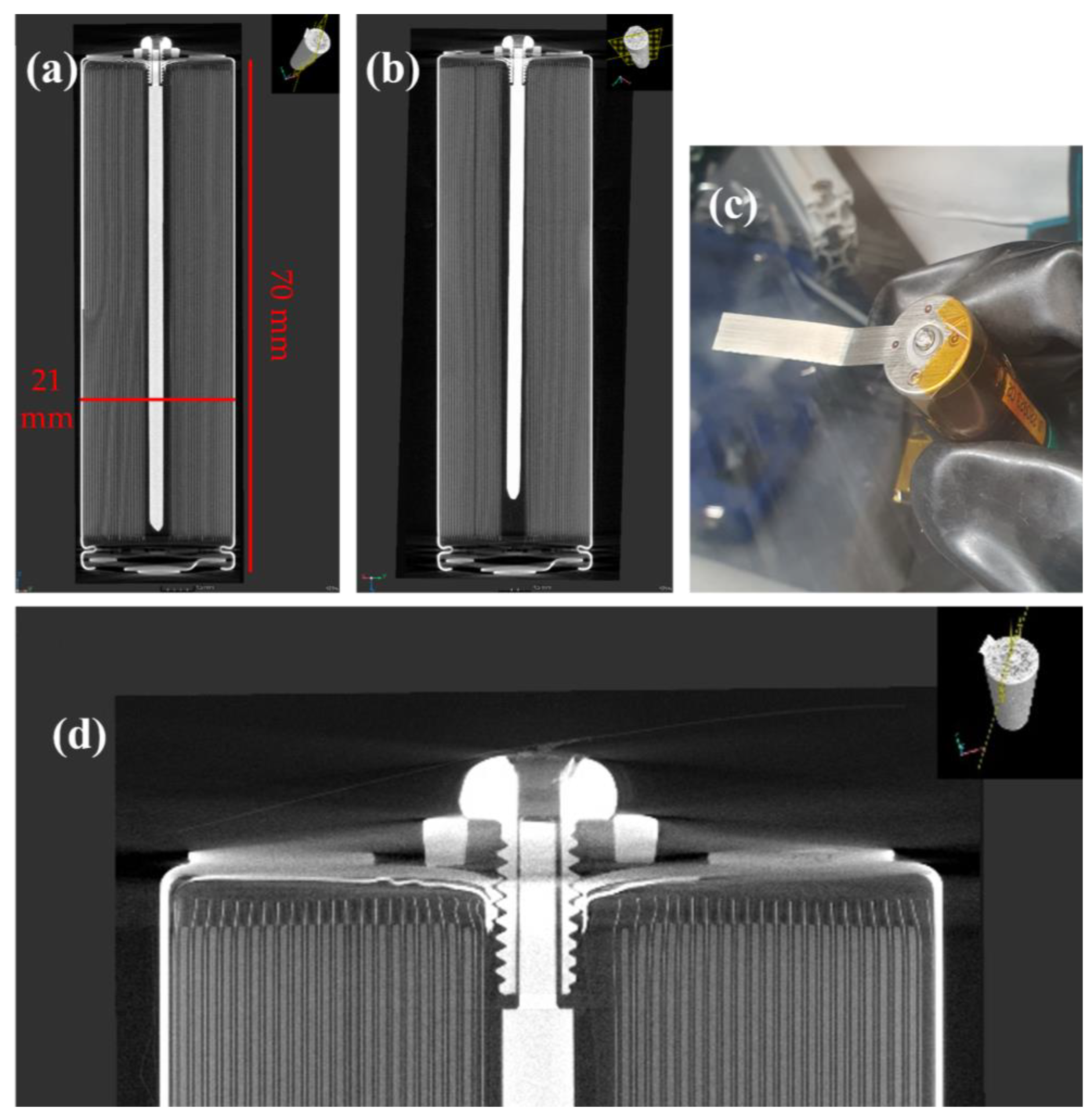
The cells had a 2 mm hole drilled through the base, then they were tapped using an M2.5 thread, and the screw and mandrel unit were inserted with a rubber sealing washer to ensure a gas-tight seal. X-ray tomography images in Figure 2a,b show the modified cell, whilst the base of the cell can be seen in Figure 2c,d.
(8–9)
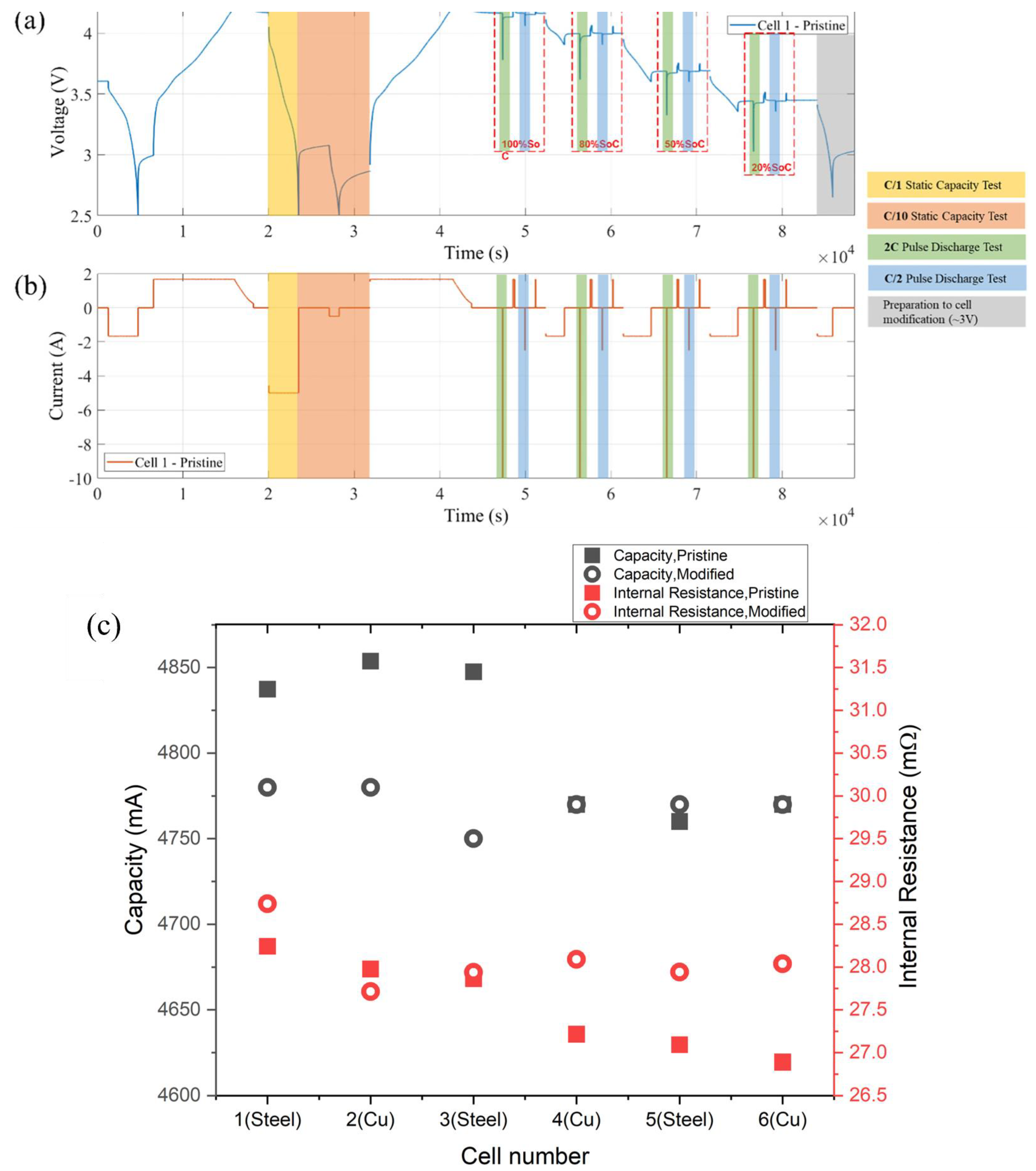
For modified cells, the same OCV and RPT were conducted to ensure the cells were not adversely affected by the inclusion of the solid mandrel, with results shown in Figure 3c.
(10)
Thermal characterisation of the cells was undertaken using the test procedure in Section 2.4.
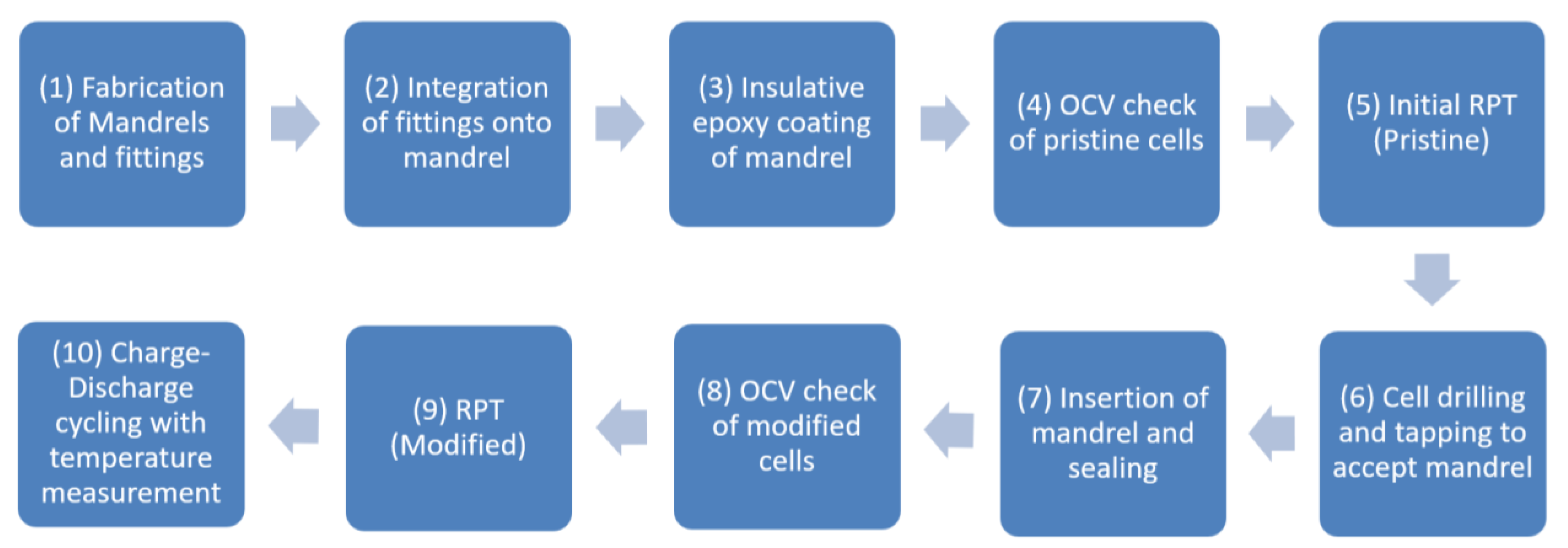
Figure 1. Process stages for modification and integration of solid mandrel into pristine cell, with verification of functionality and charge–discharge cycling.
Energies 18 01825 g001
Figure 2. X-ray computed tomography (XCT) scans of a (a) copper and (b) steel mandrel cell with (c) an external view of the modified cell base. (d) Shows an enlarged XCT scan of the cell base, where the securing screw, washer, and mandrel are all clearly visible.
Energies 18 01825 g002
Figure 3. The (a) voltage and (b) current profiles of the RPT cycle used to characterise the cells before and after modification, as used by Gulsoy et al. [19]. (c) From the RPT, the capacity (black) and internal resistance (red) of the modified cells remains consistent, showing only a small deviation from the pristine cells.
Energies 18 01825 g003

2.3. Reference Performance Tests and Functionality Verification

The RPT cycle shown in Figure 3a,b was conducted for all cells before and after modification (stages 5 and 9) to assess the impact of the drilling and mandrel insertion on cell performance. These were performed under 25 °C ambient conditions, with capacity estimation using 1 C and 0.1 C constant current–constant voltage (CC-CV) discharge rates, and DC internal resistance measurements using a 10 s pulsed discharge at 0.5 C and 2 C, and at 100%, 80%, 50%, and 20% SOC. There were no cell failures during the modification stage, with Figure 3c and Table 1 showing all cells having minimal changes in their energy capacity and a less than 5% difference in internal resistance, which has previously suggested [19] that the cells are functioning correctly. As reported in [19], this small increase in internal resistance equates to the removal of a small area of internal tab material within the cell. The full experimental procedure was completed for three copper and three stainless steel mandrels, representing a total of nine test cells (including three pristine reference cells), with the results shown in Table 1.

2.4. Experimental Setup and Test Procedure

To investigate the effect of the solid mandrel on the temperature profile of the cells, cells were arranged with their base (negative terminal) on a Wakefield Thermal 152 × 139 mm cold plate, as shown in Figure 4, with a layer of Therm-A-Gap 579 (thermal conductivity = 3 W/mK) 2.5 mm thermal pad between the cell and cold plate. The acrylic sheets provide mounting points for the brass blocks that allow for an electrical connection between the cells and the electrical cycler, in addition to providing additional downward pressure to ensure there is good thermal contact between the cells and thermal pad.
A Bitrode cell cycler recording the current and voltage at 1 Hz was used to subject all cells to a 0.7 C CC-CV charge and 1.5 C CC discharge cycle, with a cutoff voltage and current of 4.2 V and 250 mA, respectively, over the full State of Charge (SOC) of the cell, as seen in Figure 4d. This represents the maximum continuous power demand, as outlined by the manufacturer.
The coolant fluid used was a water–glycol mixture at a temperature of 15 °C, and the ambient chamber temperature was set to 25 °C. The cells were allowed to reach thermal equilibrium prior to testing for a period of 1 h. Figure 4a–c shows the location of the instrumentation within the experimental setup, which includes three K-Type thermocouples placed on the cold plate, downstream of the coolant flow and physically next to each cell. In addition, there are three sensors located on the top, middle, and base of each cell, aligned vertically with all thermocouples and connected to two Picologger data recorders operating at 1 Hz.

3. Results

3.1. Pristine Reference Cell

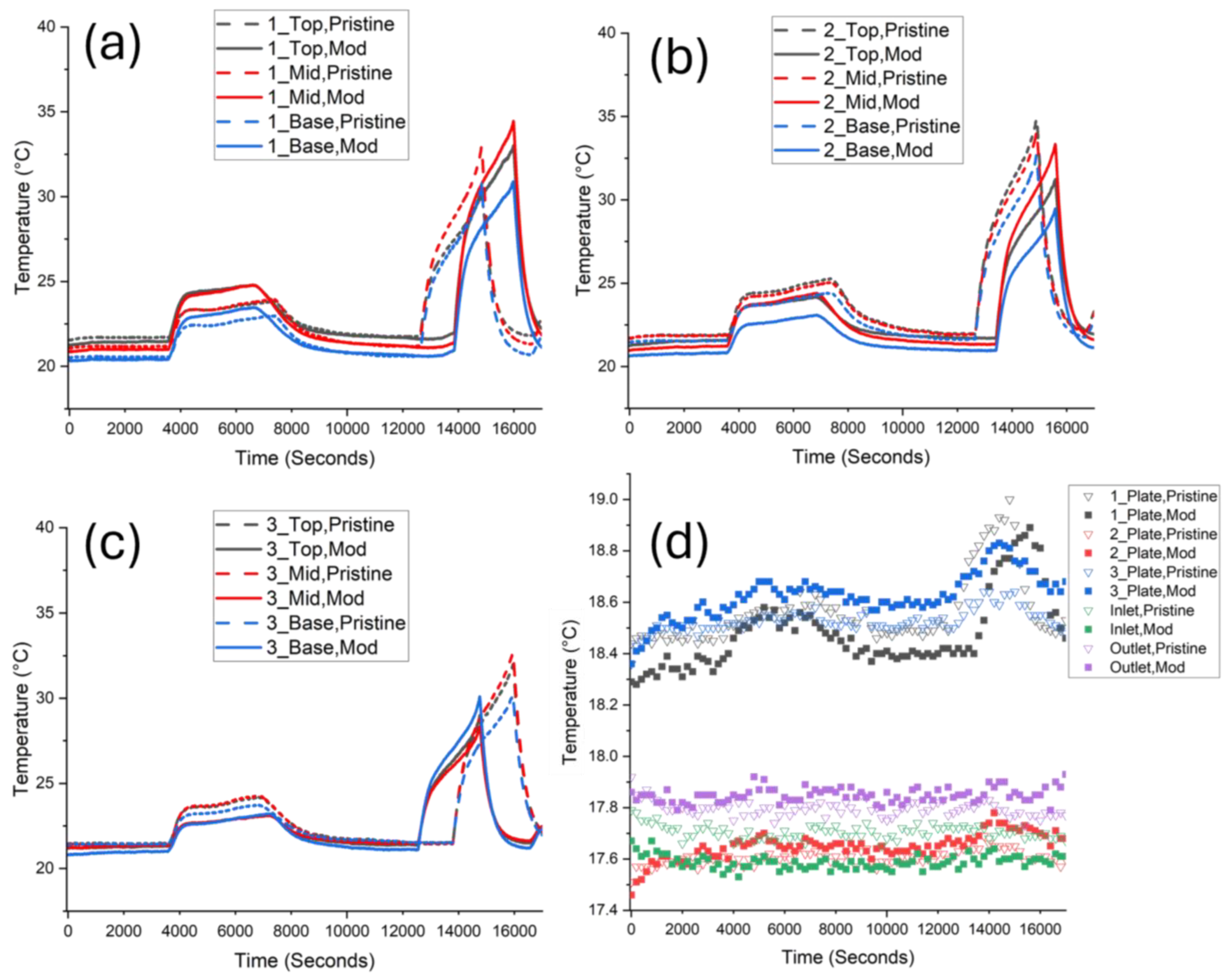
The initial results used a pristine reference cell, meaning there was a difference in the external geometry, with the modified cell having the securing screw protruding ~3 mm from the cell base. For all three cell positions in Figure 5a–c, the modified cell shows a higher temperature than the pristine cell at all sensor locations. This difference between the modified and pristine peak temperatures is largest at the cell base, with average values of 1.9, 1.0, and 5.2 °C (top, mid, base), where the modified cells also had a higher resting temperature by 1–2 °C. This increase in temperature is the opposite result to what was expected, given the results often presented in the literature. This leads us to believe that the thermal resistance between the cell and cold plate is higher for the modified cells, with the probable cause being that the protruding fitting on the base of the cell is impacting the contact area between the cell and the cold plate. Despite the use of thermal pads, the combination of the screw bulkhead and washer reduce the effective cooling area on the cell base. This deficiency, in turn, leads to reduced cooling power to the cell, and, therefore, lower heat conduction. This method of integration of the solid mandrel appears to have hindered the thermal performance, and has not allowed for the intended utilisation of the mandrel with conduction-based thermal management. It is noteworthy that this limitation has never been discussed in the literature, where convection-based cooling methods [14,16,18] have demonstrated a thermal benefit. This is counterintuitive, as the choice to use a base cold plate was to target the mandrel and provide the lowest heat resistance path to the cell core; however, the geometry and surface contact penalty appear to be a larger thermal factor than the mandrel inclusion. This suggests that the thermal management strategy for any modified cell must be carefully considered to achieve the most effective utilisation of the modification.
The temperatures measured on the cold plate in Figure 5d show that the plate temperatures next to each cell were either identical or higher for the pristine cell, implying a greater heat rejection from the cell into the cold plate. The data for cell 1 show a 0.6 °C increase for the pristine cell, but no clear peak value at the maximum heat generation point (8750 s at the end of discharge), as opposed to cells 2 and 3, which show a peak but no temperature difference between the pristine and modified cells. The highest resting temperature and largest temperature increase were observed on the cold plate at cell 2, which was expected due to it being the last cell in the coolant flow path, and thus being affected the most by the other cells’ temperature increase and ambient heating from the thermal chamber.

3.2. Modified Reference Cell

A second investigation was conducted to quantify the thermal benefit of the mandrel with identical external geometry by adding an identical screw to the base of the pristine cell so that the cells would have the same effective cooling area. The pristine cells underwent the same modification process as that discussed in Section 2.2, but they did not have a mandrel placed inside, with only the securing screw and rubber washer attached to the base. The testing was repeated under identical conditions as those discussed in Section 2.4.
Figure 6 shows that there is no clear indication as to whether the inclusion of the mandrel consistently impacts the cell temperature compared to the added screw pristine cell with max temperatures of 33.0, 35.1, and 32.7 °C for pristine hollow mandrel cells 1, 2, and 3, compared to 34.5, 33.4, and 30.1 °C, for the modified cells.
The non-uniform difference in the cell temperature is greater than the apparent effect of the mandrel, with cell 1 showing the modified cell having a higher temperature and cell 2 showing the opposite. There does appear to be a connection between the cell temperature in Figure 6a–c and the plate temperature in Figure 6d, as a comparatively higher cell temperature between a pristine and modified cell leads to a comparatively lower plate temperature. This implies that there is equal heat generation between both pristine and modified cells, but that the difference in thermal resistance between the cells and the cold plate is the main factor in the difference in cell temperature, rather than the inclusion of the solid mandrel. Both the pristine and modified reference cell do not appear to have a significant difference between the copper and stainless steel mandrels, with neither material showing a distinct thermal benefit.
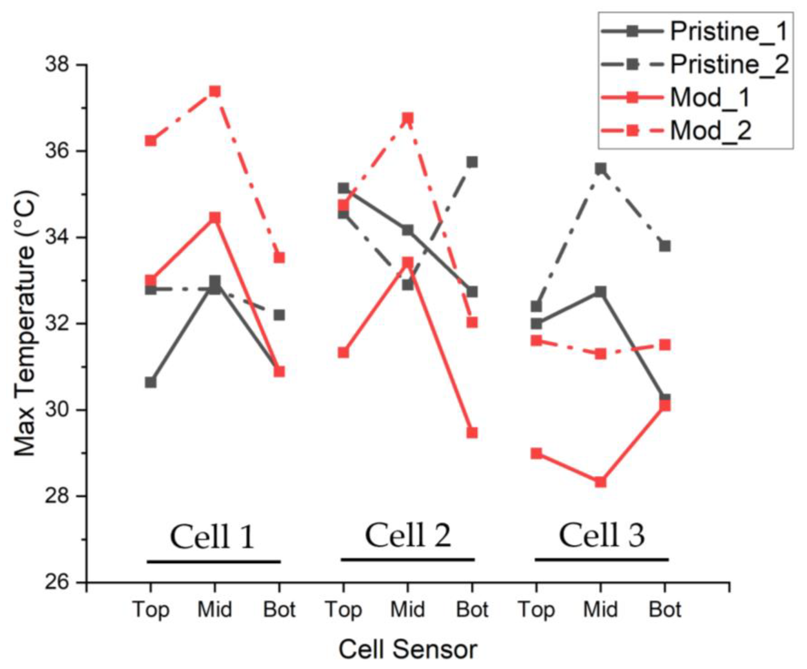
Figure 7 shows the maximum temperature of all external cell thermocouples from two separate cycles, for each cell type, and demonstrates the non-uniformity of the temperature data, with no clear reduction in temperature seen due to the inclusion of the solid mandrel.
As discussed in Section 2.1, there were two feasible approaches for this investigation, which are as follows: first, modifying an existing cell with the securing screw and washer (this study), or second, a more idealistic approach where the modifications are purely internal, leaving a flat cell base with an integrated mandrel. The evidence presented here suggests that this approach has introduced some considerable additional sources of thermal resistance, such as between the mandrel, securing screw, and the rubber washer, as well as reductions in the thermal contact for the addition of a solid mandrel to be able to demonstrate a benefit, as reported in the literature [13,14,15,16,18]. To investigate this second approach with bespoke housing, a simulation has been conducted to identify whether the concept would provide any thermal benefit as an idealised system compared to the inclusion of the limitations of real-world modifications, as well as to discuss the effect the modifications have on the thermal resistance of the system.

4. Simulation

4.1. Model Parameters and Test Cycle

The results of the previous section have not demonstrated a conclusive thermal benefit for the inclusion of the solid mandrel which is contrary to previously discussed work [13,14,15,16,18]. To investigate whether this discrepancy is caused by the base modification method employed here, Figure 8a shows a simulated 21700 cell with a solid 2 mm mandrel with a flat base, which is placed onto an aluminium liquid cold plate with water as the coolant liquid, set at 15 °C, an inlet velocity of 0.12 m/s, and an ambient temperature of 25 °C. The 21700 CAD model was created using X-ray tomography scans in Figure 2 and cell teardowns [22] to measure cell components and replicate the geometry and architecture. This was then imported into COMSOL Multiphysics version 6.2.0.278 to perform the simulated tests where the laminar flow and heat transfer in solids and fluids modules are used, as well as the lumped jelly roll model, which simulated homogeneous SOC-dependant heat generation through the jelly roll based on a measured OCV-SOC curve from the cells in Section 3.1, as seen in Figure 8b, which was also used to create the test cycle. A similar simulation strategy is reported in the literature [23,24,25], where the lumped battery model is shown to reduce complexity and simulation times whilst maintaining accuracy. The jelly roll has a 5 Ah capacity with ohmic overpotential and a dimensionless charge current of 80 mV and 0.11, respectively [26]. Materials are consistent with the real cell, with the anisotropic jelly roll thermal conductivity set to 30 W/mK (axial) and 0.3 W/mK (radial) [6,26,27,28], whereas the idealised thermal contact is assumed between all components. For the ‘no mandrel’ case, the central void is assumed to be filled with electrolytes with a thermal conductivity of 0.3 W/mK [29], and for all cases, ambient cooling by radiation is assumed on all external surfaces in a 25 °C environment.

4.2. Idealised Cell Results

The simulation represents an idealised system and appears to demonstrate the thermal benefit of a bespoke cell housing, with an integrated mandrel that was as expected. Temperature distributions seen in Figure 9a–c are taken at the end of discharge and at the peak temperature for no mandrel, copper (400 W/mK), and steel (44.5 W/mK) 2 mm mandrels, respectively. Comparing the (a) no mandrel and copper (b) mandrel cases clearly shows the mechanism by which this modification removes heat from the cell core, with the mandrel acting as a low thermal resistance path and targeting the cell hot spot. There is a 3.6 °C reduction in the max jelly roll temperature, as well as a 3 °C reduction in the cell gradient for the copper mandrel, and reductions of 1.3 °C and 1 °C for the steel mandrel. The maximum jelly roll temperature is plotted across the full charge–discharge cycle in Figure 9d, showing both the benefit of the solid mandrel as well as the impact of the higher thermal conductivity of copper compared to steel. The thermal gradient across the copper mandrel is 8.4 °C, compared to 14.4 °C for steel, with the steel mandrel only showing a significant temperature difference between itself and the surrounding jelly roll near the cell base. These results are consistent with other simulations and works where the mandrel is directly connected to or cooled by a thermal management system [13,14,15,16,18], thus demonstrating the potential benefits of mandrel inclusion.

4.3. Validation of Experimental Cell Modifications

The results from Figure 9d do not match the results that were observed in Section 3, and thus enhancements were made to the cell geometry used in the model to more closely emulate the experimental cell, namely the addition of the thermal pad and a 2 mm epoxy cap (0.3 W/mK) onto the mandrel, as seen in Figure 10a. All of the other parameters were identical, including the charge–discharge cycle, fluid flow rate, and cell materials, with only the mandrel material having changed between the electrolyte and copper, as in the previous simulation. Compared to the previous simulation results in Figure 10b, this modification gave rise to a maximum temperature increase of 2.8 °C compared to the ‘No mandrel’ ideal case, irrespective of the inclusion of the mandrel. There was almost no difference in the temperature distribution between the standard and solid mandrel cell, as seen in Figure 10c,d, with only a 0.2 °C maximum jelly roll temperature reduction. These results are consistent with the observations in Section 3.2, where there was no clear indication of a consistent temperature reduction arising from the inclusion of the cell modification. From this, we can conclude that the thermal connection of the mandrel to the cooling interface is vital in utilising the solid mandrel effectively, and without direct mandrel cooling, this approach to the internal thermal cell management has little to no effect on the thermal performance. The additional thermal resistances introduced into the cell during the mandrel inclusion process meant that the heat from the cell core was not able to be conducted easily out of the cell through the mandrel; thus, it acted as a small additional thermal capacitive mass rather than a heat conduit. This further demonstrates the proposed benefit of a bespoke cell housing, with a direct connection to the cell base to reduce this thermal resistance.

4.4. Variation of Mandrel Base Thermal Conductivity

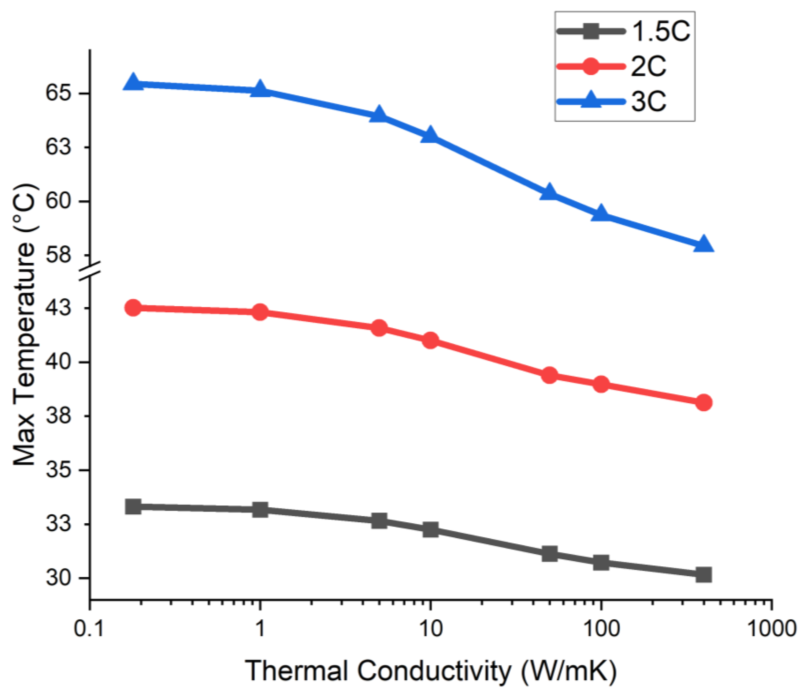
To quantify the effect of the increased thermal resistance between the mandrel and the cell base, the thermal conductivity value of the epoxy end cap varied from 0.18 W/mK (epoxy) to 400 W/mK (copper); the maximum jelly roll temperature is recorded in Figure 11 under discharge rates of 1.5 C, 2 C, and 3 C. All tests included a 2 mm copper mandrel, as used previously, with only the end cap changing in thermal conductivity and no thermal pad layer between the cell base and cold plate, with the 400 W/mK cap essentially representing a direct mandrel to base connection. Between 1–400 W/mK, the max temperature appeared to display an approximately logarithmic reduction with increasing thermal conductivity, with the largest thermal performance improvement occurring between 5–100 W/mK. There is a minor temperature reduction below 5 W/mK, and so this is the minimum value recommended to demonstrate a thermal performance benefit in this system, although a value in the 10–100 W/K range would be more beneficial. As the discharge rate increases, the increased thermal conductivity reduces the temperature more significantly, with a 7.5 °C temperature reduction from 0.18 to 400 W/mK at 3 C, compared to a 3.2 °C reduction at 1.5 C. This indicates that the mandrel is most effective at higher discharge rates and higher heat loads.
The epoxy cap fills a 2 mm space between the cell base and the base of the mandrel, so its effective thermal conductivity may be increased by either increasing the cap thermal conductivity or reducing the distance between the metal mandrel and the cell base. The direct bonding of the mandrel to the base would be the ideal case, making this distance essentially zero. If this is not possible, then minimising this distance would increase the effective thermal conductivity between the mandrel and cell base and lead to more effective utilisation of the mandrel.

5. Discussion

The results shown in this paper identify the necessity of a high thermal conductivity path between the thermal management system and the solid mandrel for a benefit to be realisable in a physical system. This would most likely be achieved through the design and manufacture of a bespoke cell housing, with a solid mandrel directly bonded to the base of the cell during the construction process rather than a retroactive addition, as proposed in this paper. As identified in Section 2.1, this approach would incur additional cost and manufacturing demands. Due to these additional requirements, the utilisation of this concept would be most appropriate for high power and lower volume manufacturing, where the cost factor is not as vital as the thermal performance and, thus, the additional manufacturing processes can be justified more readily.
The construction and integration of a bespoke cell housing is recommended as future work, as this work suggests that these concepts would show greater thermal benefits compared to the standalone mandrel integration. This experimental validation may also have benefits for different cell form factors (18650, 32112, 4680, etc.) and tab architecture (multi-tab and tabless) with similar housing and mandrel construction, with consideration to the comparative increase in heat load and physical size for each format, as well as the internal heat distribution and thermal resistances of different tab architectures. Assuming that this concept would remove heat from the cell core, this additional heat load must be considered at a system level when designing a BTMS to reduce the risk of cell overheating, and heat propagation to maintain optimal operating temperatures.

6. Conclusions

Cylindrical Li-ion cells rely on effective thermal management for safe and efficient functioning. Modifications to the internal structure of these cells have been proposed by integrating a solid metal mandrel down the central void of the jelly roll to act as a high-conductivity thermal pathway to extract heat from the cell core. Previous works have identified, through simulation, thermal emulation, and custom-built functional cells, that there can be a considerable thermal benefit to the inclusion of the central mandrel in reducing both the maximum temperature and thermal gradients in all directions within the cell. The proposed solution in this work involves the modification of a commercial 21700 cell by inserting a 2 mm diameter high thermal conductivity solid metal mandrel through a hole in the base of the cell and using a conduction-based cold plate thermal management system. These cells were shown to generate higher temperatures between 1.0–5.2 °C when compared to a pristine reference cell, due to the reduction in the effective cooling contact area on the cell base, as well as additional thermal resistances introduced in the modification process from the screw and rubber washer used to secure the mandrel. The pristine cells were then externally modified with the same screw and rubber washers to produce an equally effective cooling area, which resulted in no clear thermal difference between the standard and solid mandrel cells.
To this investigate further, a simulation was completed using COMSOL Multiphysics to quantify the difference between an ideal system and the realistic modification undertaken. The ideal system demonstrated a similar performance to the previous literature, with the copper mandrel showing a 3.6 °C reduction in the max jelly roll temperature, as well as a 3 °C reduction in the cell gradient, and reductions of 1.3 °C and 1 °C for the steel mandrel when compared to a pristine cell. The introduction of the realistic modifications, namely a thermal contact pad and epoxy cap on the base of the mandrel, severely impacted thermal performance, and lead to only a 0.2 °C maximum jelly roll temperature reduction for the copper mandrel. This aligned with the results from the experimental work, where no consistent thermal benefit could be identified from mandrel inclusion, suggesting that the potential benefit is limited by the mandrel integration method. By coupling these results with the idealised simulations, we can see that the significant thermal performance benefits reported in the literature have been in cells that do not represent the realistic modifications of commercially available cells, and, hence, have limited real-world applicability. The presented modification procedure appears to not address the issue fully, with the connection between the mandrel, cell housing, and the cooling interface being the main limiting issue.
Given this information, it is recommended that the thermal resistance between the cooling interface and solid mandrel be minimised in order for the mandrel to have a positive impact on the cell thermal profile, with a recommended effective thermal conductivity of above 5 W/mK. In order to achieve this, we suggest the manufacture of a bespoke cell housing, with an integrated mandrel in the cell base in order to interface directly with a cooling system and allow the mandrel to be cooled directly, rather than requiring the introduction of a mandrel after manufacture. This was shown to reduce the maximum jelly roll temperature by 7.2 °C during a 3 C discharge, and is similar to concepts proposed in previous works. As previously discussed, this would be a more costly approach, but based on both the literature and the work presented here, it utilises the mandrel thermal properties more effectively and assists in thermal management of the cell.

Author Contributions

Conceptualisation, J.I., J.M., R.M. and K.L.; methodology, J.I.; formal analysis, J.I.; investigation, J.I.; writing—original draft preparation, J.I.; writing—review and editing, J.I., J.M., T.D. and R.M.; supervision, J.M. and T.D.; funding acquisition, J.M. and R.M. All authors have read and agreed to the published version of the manuscript.

Funding

This research was supported by BOYD Corporation through the Warwick Industrial Fellowship programme, University of Warwick, No. 73915.

Data Availability Statement

The original contributions presented in the study are included in the article, further inquiries can be directed to the corresponding author.

Acknowledgments

This research was conducted within the Energy Innovation Centre (EIC) at WMG, University of Warwick, where we are thankful for the support from the cell modification and battery lab teams.

Conflicts of Interest

Authors Ryan McGlen and Kevin Lynn were employed by Boyd Corporation. The remaining authors declare that the research was conducted in the absence of any commercial or financial relationships that could be construed as a potential conflict of interest.

References

  1. Baazouzi, S.; Feistel, N.; Wanner, J.; Landwehr, I.; Fill, A.; Birke, K.P. Design, Properties, and Manufacturing of Cylindrical Li-Ion Battery Cells—A Generic Overview. Batteries 2023, 9, 309. [Google Scholar] [CrossRef]
  2. Yan, H.; Marr, K.C.; Ezekoye, O.A. Towards Fire Forensic Characteristics of Failed Cylindrical Format Lithium–Ion Cells and Batteries. Fire Technol. 2021, 57, 1723–1752. [Google Scholar] [CrossRef]
  3. Goodenough, J.B.; Park, K.-S. The Li-Ion Rechargeable Battery: A Perspective. J. Am. Chem. Soc. 2013, 135, 1167–1176. [Google Scholar] [CrossRef] [PubMed]
  4. Tranter, T.G.; Timms, R.; Shearing, P.R.; Brett, D.J.L. Communication—Prediction of Thermal Issues for Larger Format 4680 Cylindrical Cells and Their Mitigation with Enhanced Current Collection. J. Electrochem. Soc. 2020, 167, 160544. [Google Scholar] [CrossRef]
  5. Tran, M.-K.; Mevawalla, A.; Aziz, A.; Panchal, S.; Xie, Y.; Fowler, M. A Review of Lithium-Ion Battery Thermal Runaway Modeling and Diagnosis Approaches. Processes 2022, 10, 1192. [Google Scholar] [CrossRef]
  6. Drake, S.; Wetz, D.; Ostanek, J.; Miller, S.; Heinzel, J.; Jain, A. Measurement of anisotropic thermophysical properties of cylindrical Li-ion cells. J. Power Sources 2014, 252, 298–304. [Google Scholar] [CrossRef]
  7. Fleckenstein, M.; Bohlen, O.; Roscher, M.A.; Bäker, B. Current density and state of charge inhomogeneities in Li-ion battery cells with LiFePO4 as cathode material due to temperature gradients. J. Power Sources 2011, 196, 4769–4778. [Google Scholar] [CrossRef]
  8. Nguyen, T.; Deng, J.; Robert, B.; Chen, W.; Siegmund, T. Experimental investigation on cooling of prismatic battery cells through cell integrated features. Energy 2022, 244, 122580. [Google Scholar] [CrossRef]
  9. Kleiner, J.; Lambauer, F.; Singh, R.; Komsiyska, L.; Hinterberger, M.; Endisch, C. Experimental study of cell integrated heat pipe cooling with a lithium-ion cell emulator. J. Energy Storage 2022, 56, 105808. [Google Scholar] [CrossRef]
  10. Tran, T.-H.; Harmand, S.; Sahut, B. Experimental investigation on heat pipe cooling for Hybrid Electric Vehicle and Electric Vehicle lithium-ion battery. J. Power Sources 2014, 265, 262–272. [Google Scholar] [CrossRef]
  11. Mo, X.; Hu, X.; Tang, J.; Tian, H. A comprehensive investigation on thermal management of large-capacity pouch cell using micro heat pipe array. Int. J. Energy Res. 2019, 43, 7444–7458. [Google Scholar] [CrossRef]
  12. Li, S.; Kirkaldy, N.; Zhang, C.; Gopalakrishnan, K.; Amietszajew, T.; Diaz, L.B.; Barreras, J.V.; Shams, M.; Hua, X.; Patel, Y.; et al. Optimal cell tab design and cooling strategy for cylindrical lithium-ion batteries. J. Power Sources 2021, 492, 229594. [Google Scholar] [CrossRef]
  13. Sievers, M.; Sievers, U.; Mao, S.S. Thermal modelling of new Li-ion cell design modifications. Forsch. Ingenieurwesen 2010, 74, 215–231. [Google Scholar] [CrossRef]
  14. Shah, K.; McKee, C.; Chalise, D.; Jain, A. Experimental and numerical investigation of core cooling of Li-ion cells using heat pipes. Energy 2016, 113, 852–860. [Google Scholar] [CrossRef]
  15. Worwood, D.; Kellner, Q.; Wojtala, M.; Widanage, W.; McGlen, R.; Greenwood, D.; Marco, J. A new approach to the internal thermal management of cylindrical battery cells for automotive applications. J. Power Sources 2017, 346, 151–166. [Google Scholar] [CrossRef]
  16. Gou, J.; Liu, W.; Luo, Y. The thermal performance of a novel internal cooling method for the electric vehicle battery: An experimental study. Appl. Therm. Eng. 2019, 161, 114102. [Google Scholar] [CrossRef]
  17. Waldmann, T.; Scurtu, R.-G.; Richter, K.; Wohlfahrt-Mehrens, M. 18650 vs. 21700 Li-ion cells—A direct comparison of electrochemical, thermal, and geometrical properties. J. Power Sources 2020, 472, 228614. [Google Scholar] [CrossRef]
  18. Anthony, D.; Wong, D.; Wetz, D.; Jain, A. Improved Thermal Performance of a Li-Ion Cell through Heat Pipe Insertion. J. Electrochem. Soc. 2017, 164, 961–967. [Google Scholar] [CrossRef]
  19. Gulsoy, B.; Vincent, T.; Sansom, J.; Marco, J. In-situ temperature monitoring of a lithium-ion battery using an embedded thermocouple for smart battery applications. J. Energy Storage 2022, 54, 105260. [Google Scholar] [CrossRef]
  20. Vincent, T.A.; Gulsoy, B.; Sansom, J.E.; Marco, J. In-situ instrumentation of cells and power line communication data acquisition towards smart cell development. J. Energy Storage 2022, 50, 104218. [Google Scholar] [CrossRef]
  21. Chen, S.; Wan, C.; Wang, Y. Thermal analysis of lithium-ion batteries. J. Power Sources 2005, 140, 111–124. [Google Scholar] [CrossRef]
  22. Droese, D.; Luc, P.-M.; Otto, M.; Schlösser, A.E.K.; Evans, D.; Kowal, J. Comparison and Teardown of Na- and Li-Ion 18650 Cells. SSRN 2024. [Google Scholar] [CrossRef]
  23. Sarmadian, A.; Widanage, W.D.; Shollock, B.; Restuccia, F. Experimentally-verified thermal-electrochemical simulations of a cylindrical battery using physics-based, simplified and generalised lumped models. J. Energy Storage 2023, 70, 107910. [Google Scholar] [CrossRef]
  24. Özdemir, T.; Amini, A.; Ekici, Ö.; Köksal, M. Experimental Assessment of the Lumped Lithium Ion Battery Model at Different Operating Conditions. Heat Transf. Eng. 2021, 43, 314–325. [Google Scholar] [CrossRef]
  25. Ireland, J.C.; Marco, J.; McGlen, R. The effect of increasing the thermal conductivity of a cylindrical cell housing on thermal performance. In Proceedings of the 2024 IEEE Vehicle Power and Propulsion Conference (VPPC), Washington DC, USA, 7–10 October 2024; pp. 1–6. [Google Scholar]
  26. Sarmadian, A.; Yu, Y.; Marco, J.; Shollock, B.; Restuccia, F. An Experimentally-Verified Thermal-Electrochemical Simulation Model of a 21700 Cell Using a Lumped Semi-Empirical Battery Model. In Proceedings of the 16th International Conference on Heat Transfer, Fluid Mechanics and Thermodynamics, Virtual Conference, 8–10 August 2022; pp. 128–133. [Google Scholar]
  27. Fleckenstein, M.; Fischer, S.; Bohlen, O.; Bäker, B. Thermal Impedance Spectroscopy—A method for the thermal characterization of high power battery cells. J. Power Sources 2013, 223, 259–267. [Google Scholar] [CrossRef]
  28. Maleki, H.; Al Hallaj, S.; Selman, J.R.; Dinwiddie, R.B.; Wang, H. Thermal Properties of Lithium-Ion Battery and Components. J. Electrochem. Soc. 1999, 146, 947–954. [Google Scholar] [CrossRef]
  29. Böger, T.; Bernges, T.; Li, Y.; Canepa, P.; Zeier, W.G. Thermal Conductivities of Lithium-Ion-Conducting Solid Electrolytes. ACS Appl. Energy Mater. 2023, 6, 10704–10712. [Google Scholar] [CrossRef]
Figure 4. (a) Top-down view of test cell arrangement on cold plate, (b) side view of assembled test-rig with thermocouples attached to cell side, and (c) diagram of modified cell with thermocouple placement and solid mandrel. (d) Shows the 0.7 C CC-CV charge, 1.5 C CC discharge test cycle for each cell.
Energies 18 01825 g004
Figure 5. Temperature data from the 0.7 C–1.5 C charge–discharge cycle used to compare the modified (solid) and pristine cells (dashed) for cells 1, 2, and 3 (ac). (d) Shows the temperature on the plate surface next to each cell, as well as the inlet and outlet temperatures.
Energies 18 01825 g005
Figure 6. Temperature data from the 0.7 C–1.5 C charge–discharge cycle used to compare the modified (solid) and pristine cells with the added base screw (dashed) for cells 1, 2, and 3 (ac). (d) Shows the temperature on the plate surface next to each cell, as well as the inlet and outlet.
Energies 18 01825 g006
Figure 7. Maximum sensor temperature for pristine (black) and modified (red) cells from two separate test runs per cell type.
Energies 18 01825 g007
Figure 8. (a) CAD model of the simulated 21700 cell on a liquid cold plate and (b) the 0.7 C charge, 1.5 C discharge cycle used in the simulation using the OCV-SOC curve from the previous testing.
Energies 18 01825 g008
Figure 9. Temperature distribution of the cell with (a) no mandrel, (b) copper, and (c) steel mandrel with 2 mm diameter. (d) Additionally, the maximum external housing temperatures through the charge–discharge cycle are shown for all three cases.
Energies 18 01825 g009
Figure 10. (a) Diagram of added components with epoxy plug (blue) and thermal pad (green). (b) Maximum external housing temperature between ideal simulations (solid) and modified simulation (dashed), as well as thermal distribution at the end of discharge for the modified (c) copper mandrel and (d) no mandrel cells, showing very little difference.
Energies 18 01825 g010
Figure 11. Maximum jelly roll temperature with copper mandrel, whilst varying thermal conductivity of an epoxy end cap restricts thermal resistance between the mandrel and cell base under 1.5 C, 2 C, and 3 C discharge rates.
Energies 18 01825 g011
Table 1. RPT results showing the capacity and internal resistance of all cells used. Cells 7–9 were the pristine cells, so no ‘modified’ test was conducted.
Capacity (mAh)Internal Resistance (mΩ)
Cell IDPristineModifiedChangePristineModifiedChange
148374780−1.2%28.2428.741.8%
248534780−1.5%27.9827.71−0.9%
348474750−2.0%27.8627.940.3%
4477047700.0%27.2128.093.2%
5476047700.2%27.0927.943.1%
6477047700.0%26.8928.044.3%
74800 27.17
84820 27.14
94780 27.47
Disclaimer/Publisher’s Note: The statements, opinions and data contained in all publications are solely those of the individual author(s) and contributor(s) and not of MDPI and/or the editor(s). MDPI and/or the editor(s) disclaim responsibility for any injury to people or property resulting from any ideas, methods, instructions or products referred to in the content.