Article

A Comprehensive System for Protection of Photovoltaic Installations in Normal and Emergency Conditions

by
Konrad Seklecki
1,
Marek Olesz
1,
Marek Adamowicz
1,
Mikołaj Nowak
1,
Leszek Sławomir Litzbarski
1,2,3,*,
Kamil Balcarek
2 and
Jacek Grochowski
4
1
Faculty of Electrical and Control Engineering, Gdansk University of Technology, Narutowicza 11/12, 80-233 Gdansk, Poland
2
Faculty of Applied Physics and Mathematics, Gdansk University of Technology, Narutowicza 11/12, 80-233 Gdansk, Poland
3
Advanced Materials Centre, Gdansk University of Technology, Narutowicza 11/12, 80-233 Gdansk, Poland
4
Faculty of Control, Robotics and Electrical Engineering, Poznan University of Technology, Marii Skłodowskiej-Curie 5, 60-965 Poznań, Poland
*
Author to whom correspondence should be addressed.
Energies 2025, 18(7), 1749; https://doi.org/10.3390/en18071749
Submission received: 7 March 2025 / Revised: 24 March 2025 / Accepted: 27 March 2025 / Published: 31 March 2025
(This article belongs to the Section A2: Solar Energy and Photovoltaic Systems)

Abstract

:
The rapid growth of the photovoltaic industry necessitates the development of innovative solutions to ensure the safe operation of these systems. One of the most critical challenges in photovoltaic installations is ensuring protection against electric shock under both operational and emergency conditions, as well as minimizing the risk of fire spread in case of an installation fire. Existing safety measures do not provide a sufficient level of protection, particularly in terms of fire safety. To address these shortcomings, a comprehensive safety system has been developed. This system includes a photovoltaic panel shutter and a safety switch device, which enables the short-circuiting of individual panel outputs while also providing a break in the DC circuit. The proposed solution can be classified as part of the Balance of System (BoS). The effectiveness of this safety system has been validated through both numerical simulations and experimental investigations. Furthermore, an economic analysis indicates that implementing this system will not significantly impact the overall cost of a photovoltaic system.

1. Introduction

The dynamic development of technology and the global trend towards obtaining “green” electricity have led to a significant increase in the number of photovoltaic (PV) installations in residential construction, as well as in professional energy sectors (Rynska, 2022) [1]. This is conditioned by the relatively low cost of PV installations, the ease of installation in diverse environments (e.g., installations on building roofs, facades, free-standing PV farms), and the good scalability of the system. An additional factor contributing to the growing popularity of this type of electricity generators are various grants and subsidies, such as the “Mój Prąd” (“My Electricity”) program financed by the Polish state as part of the effort to meet CO2 emission standards [2] or the British Smart Export Guarantee program, which enables small, low-emission electricity producers to receive payments for the excess energy they export back to the grid [3]. This phenomenon has intensified interest in research concerning the safety of PV installations. In the literature, one can find information regarding the impact of PV systems on various related aspects, such as protection against electric shock [4,5,6], lightning and surge protection [7,8,9,10], fire safety [11,12,13], and issues related to the mechanical strength of buildings [14,15]. Nevertheless, the current state of technical knowledge in this area leaves many unresolved problems. One of the more important issues related to this topic concerns the protection against electric shocks for people near PV installations, both in operational and emergency conditions [11,16]. It is also necessary to pay attention to potential fires in PV installations and the problems associated with extinguishing them [17,18,19]. Research has shown that even partially burned PV modules are capable of generating electrical energy [20], which, when combined with insulation damage, can lead to the appearance of dangerous voltage. This poses an additional risk for firefighters involved in extinguishing the fire and bystanders near the incident site. Moreover, the electric arc that forms when the galvanic continuity of the DC wires is interrupted can become an additional source of fire [21], thus spreading the blaze and increasing potential losses.
At this point, it should be noted that although the primary component of any photovoltaic installation are PV panels responsible for generating electricity, they could not fulfill their role without other elements such as cabling, switches, mounting systems, inverters, energy storage, etc. All these elements are referred to as the Balance of System (BoS) [22] and are responsible for the overall performance of the PV installation. Besides the standard elements necessary for the functioning of a given PV installation, various systems integrated with photovoltaic modules that enhance their functionality can also be considered part of the BoS. An example of introducing mechanical elements into PV systems can be integrated cleaning systems described in articles [23,24,25]. Contaminants accumulating on the surface of PV modules contribute to a decrease in their efficiency [26,27,28] and can cause the so-called hot-spot effect [29], which accelerates their degradation and increases the risk of fire. Another way to increase the efficiency of PV installations is to integrate PV panels with heat collectors, as described in publications [30,31,32]. This approach not only reduces the temperature of PV modules, which significantly impacts their efficiency, but also allows for the recovery of heat for cogeneration purposes (e.g., heating domestic hot water). The proposed solution also indirectly enhances the operational safety of PV installations by preventing them from overheating, which could potentially cause a fire.
This paper presents a comprehensive safety system for PV installations, which consists of mechanical shutters that block light access to the PV panels and the safety switching device that enables automatic short-circuiting of the outputs of individual panels and disconnection of the DC installation. This is an innovative solution that enhances the safety of PV installations both under operational and emergency conditions by minimizing the risk of electric shock and limiting the spread of fire.

2. Conception of a Safety System for PV Installations

There are many systems and methods for preventing photovoltaic panel fires described in the scientific literature [33,34]. Such systems can be divided into many groups. The first of these are Arc Fault Circuit Interrupters, abbreviated as AFCIs [35]. Ground-Fault protective devices were also analyzed [36,37]. The next group is the so-called Rapid Shutdown Devices. The purpose of such devices is to disconnect photovoltaic panels from the circuit in the event of a fire. An alternative method is to use the thermal imaging defect detection system, which enables the detection of local overheating points on photovoltaic panels during their operation. The tested system successfully detected inoperative modules, hot-spots, shadowing, and faulty connections [38]. As damaged, faulty, or corroded components can lead to abnormal temperature distribution of photovoltaic elements, Infrared Thermography (IRTG) is used to analyze the condition of photovoltaic elements in real time. Another advantage of using IRTG is its non-invasiveness, as well as its versatility. It allows for applications in both small photovoltaic facilities and large photovoltaic power plants [39]. It is also possible to reduce the flammability of certain PV modules by encapsulating them using fire-retardant materials [40]. In recent years, systems using artificial intelligence (AI) have been developed for fire-fighting applications of photovoltaic panels [41]. Using Fast Fourier Transform (FFT) analysis and AI, DC arcs were successfully detected for electrical installations in time less than 200 ms from arc initiation [42].
The safety issues of photovoltaic systems have become increasingly popular in recent years (see Figure 1). Nevertheless, the analysis of existing solutions shows that there is no appropriate safety system that would protect PV installations in the case of fire. The most dangerous aspects of such situations include the problem of increased fire propagation due to flammability of PV modules (especially for rooftop PV installations) and electric shock, which may be a consequence of direct contact with the damaged part of PV system e.g., during firefighting. For this reason, a comprehensive system is proposed, consisting of blinds limiting irradiation and blocking the spread of fire collaborating with safety switching devices (additionally limiting the output voltage of the PV source to a safe level and introducing separation from the AC voltage network).

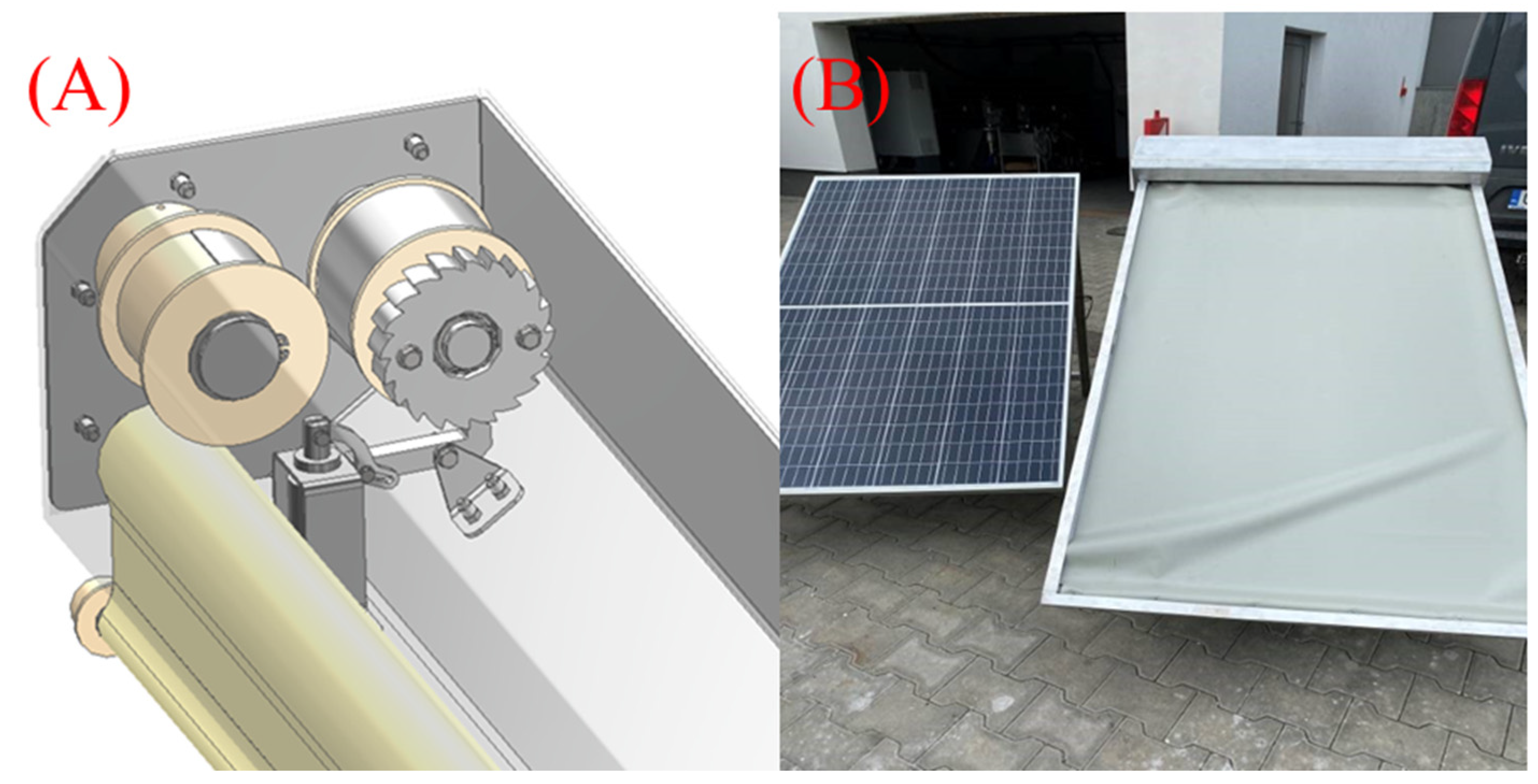
2.1. A Blind Limiting UV Radiation Access to PV Panels

The primary issue associated with PV systems is the inability to disconnect them on the DC side during maintenance work or in emergency situations such as a building fire. In contrast to typical electric power generators, PV modules cannot be switched off in a simple way. The voltage occurs continuously in the output of PV panels, which is a consequence of their construction (a serial connection of numerous p-n junctions) [43]. Photons, which are a quantum of electromagnetic radiation (including sunlight) are necessary to cause the photoelectric effect, which lead to electrical current generation [44]. The source of energy required to initiate the photoelectric effect is not only sunlight but also artificial lighting. Illuminating PV panels with floodlights or firelights allows for them to generate electric current even at night. In response to the above issue, a shutter (blind) was proposed that can cover photovoltaic panels automatically or at the user’s request in order to limit the radiation absorbed by them (see Figure 2).
In terms of potential technical solutions, various methods of powering and controlling the aforementioned shutter system had to be considered. Due to technical complexity, significant cost increase, and issues with protection against electric shocks, it was decided to avoid electrical motors in this purpose. The optimal solution chosen was a system based on gravitational force, supported by a spring storage mechanism, which is rather simple in construction and provides a high reliability. Under normal operating conditions, the deploying mechanism is immobilized by a brake held by a solenoid. The loss of voltage associated with activating the fire alarm switch, emergency switch, or fire sensors causes the brake to release. The advantage of this solution is that the shutter operates even if the power supply cables are damaged by fire, as this will cause a voltage drop on the coil. Releasing the brake causes the tensioning roller to start rotating due to the mechanical energy stored in the spring. Simultaneously, this spring sets another roller in motion, responsible for winding up the cable that controls the deployment of the shutter material. The control of the shutter can be based on signals from various sources. The basic idea is to connect the shutters to elements of fire protection systems, such as fire alarm panels or manual call points, allowing for them to be activated in emergency situations. Signals from the inverter or charge controller can also be used for this purpose, which would automatically block the generation of current in case of their failure. Additionally, the shutters can be equipped with a local control system that enables covering the panels during maintenance or service work related to the PV installation or work being performed nearby. This would reduce the potential risk for workers operating facilities equipped with such installations.
Figure 3B shows the prototype of the mentioned blind, which consists of an aluminum frame attached to a PV panel and a cassette in which the roller shutter material is stored under normal conditions. The shutter is made of fireproof, insulating fabric that does not let sunlight through. This material is wound on a shaft with a guide roller on its ends that is designed to move freely around the device frame. The frame of the device also acts as a guide, which ensures the even unwinding of the shutter and prevents it from rolling up, e.g., due to the wind. The role of the mechanism responsible for the unwinding of the shutter is played by a mechanical energy storage based on a spring with a constant tension, shown in Figure 3A, which is activated by a relay. The described device has two main functions related to the fire of the PV installation. Firstly, it is responsible for limiting the access of sunlight to the PV panels, which results in limiting the photoelectric effect. As a result, the intensity of the current generated by the photovoltaic module drops to very low values. This method is known in the literature as a disruption technique and is widely used in the form of tarpaulins manually deployed by firefighters during a fire, which is associated with additional risks, e.g., electric shock due to contact of wet material with damaged live equipment [18]. The second task of the blind is to limit the spread of fire in the event that the panel catches fire. In such a case, the shutter could act as a fire blanket. The utilization of the automatic systems allows for achieving a reduction in PV installation power without endangering firefighters and makes it possible to suppress the fire in its early stage, thus limiting potential losses.

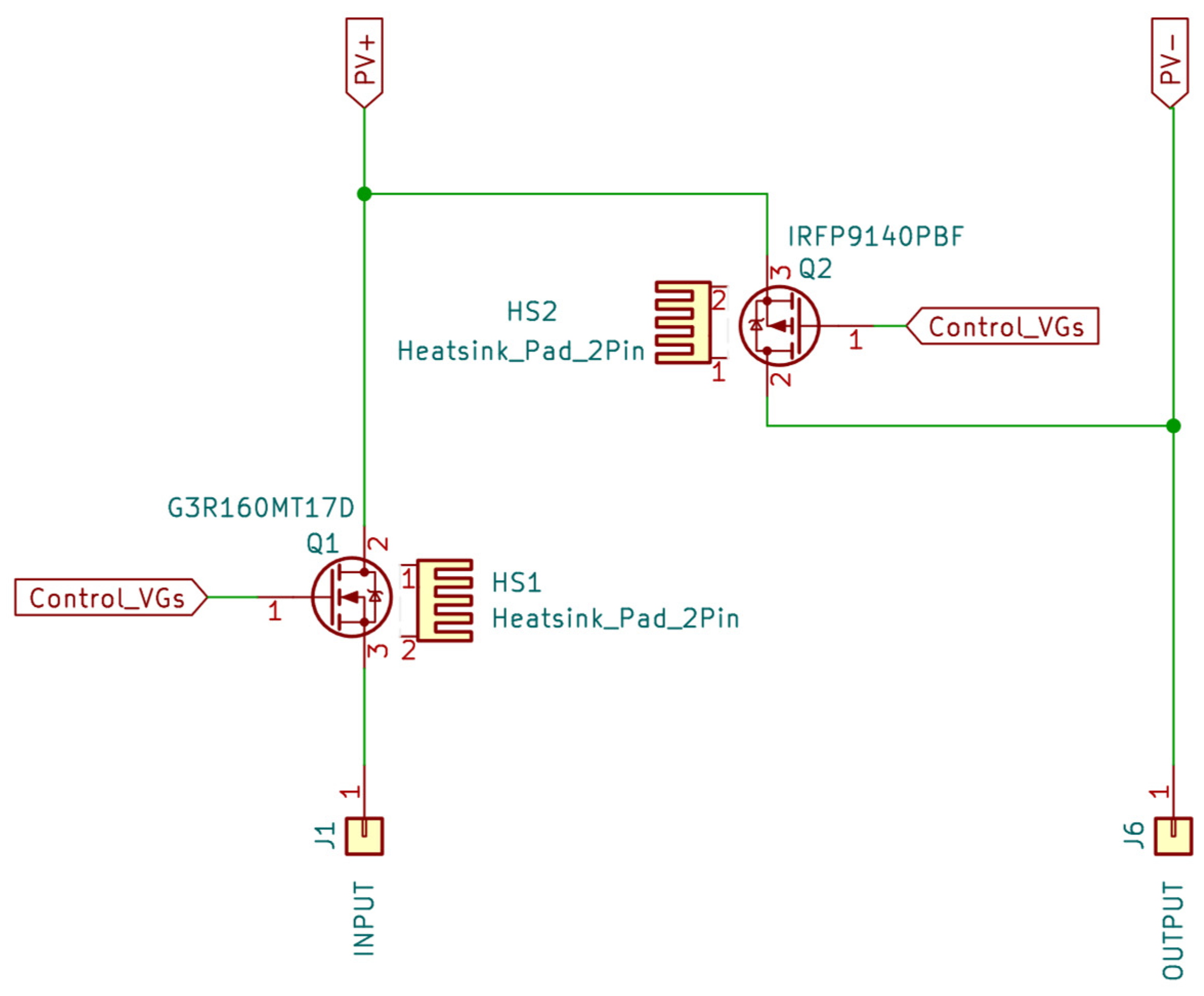
2.2. Limiting the Voltage of PV Panels Using a Safety Switching Device

Covering the PV panels limits the intensity of the generated electric current, which undoubtedly translates into the value of the expected shock current, but does not directly translate into a voltage drop to the safe value specified in the IEC 60364 standard (U = 60 V). The simplest solution to this problem is employing an electronic device that will force the output contacts of the photovoltaic panels to be shorted and thus prevent the generated electric current from being released outside the panels [45]. This article presents an extension of this conception as a safety switch, which is based on two functions: The first one involves short-circuiting individual panels in a chain using a signal from an external source, e.g., the building fire protection system. This allows for the voltage of this module to be reduced to almost zero. The second function of the system is to disconnect entire chains consisting of many PV modules. An additional function of the device is the ability to disconnect individual panels in order to maintain the continuity of the chain in the event of a failure of one of the panels. The operating principle of this innovative system is presented in Figure 4.
As in the case of the shutter described in Section 2.1, it was necessary to take into account various possibilities of powering the device and analyze the available control signals. As the optimal solution for the power supply, the voltage generated by the PV panels was utilized. This approach avoids the issues associated with running power cables or using batteries. When it comes to choosing the control method, it was decided to use the same signals that control the shutter. This allows for both devices to operate synergistically as part of a comprehensive photovoltaic system protection. This approach represents an innovation compared to existing market solutions and provides a higher level of protection than currently available systems.
A conception of a safety switching device is exhibited in Figure A1. The mentioned device has been designed in such a way that the loss of the control signal, e.g., due to burnout of wires, will cause the entire chain to be disconnected. This device is made based on MOSFET transistors, the parameters of which have been selected in such a way that it can work with both a single PV panel and a chain of series-connected modules.
The described apparatus combined with the shutter covering the photovoltaic panels is designed to enhance the safety of PV installations in normal as well as emergency conditions. This system reduces both the current intensity and the voltage generated by the PV installation, which limits the risk of electrocution and fire caused by an electric arc. Moreover, in the case of fire this system reduces its propagation.

3. Numerical Simulations of the Proposed System

Before the implementation of the proposed safety system for PV installations, numerical simulations were performed, aiming to demonstrate the validity of the assumptions made. For this purpose, it was decided to estimate the impact of individual system components on limiting the voltage and current generated by the PV installation and the ability of the shutter to reduce fire propagation.

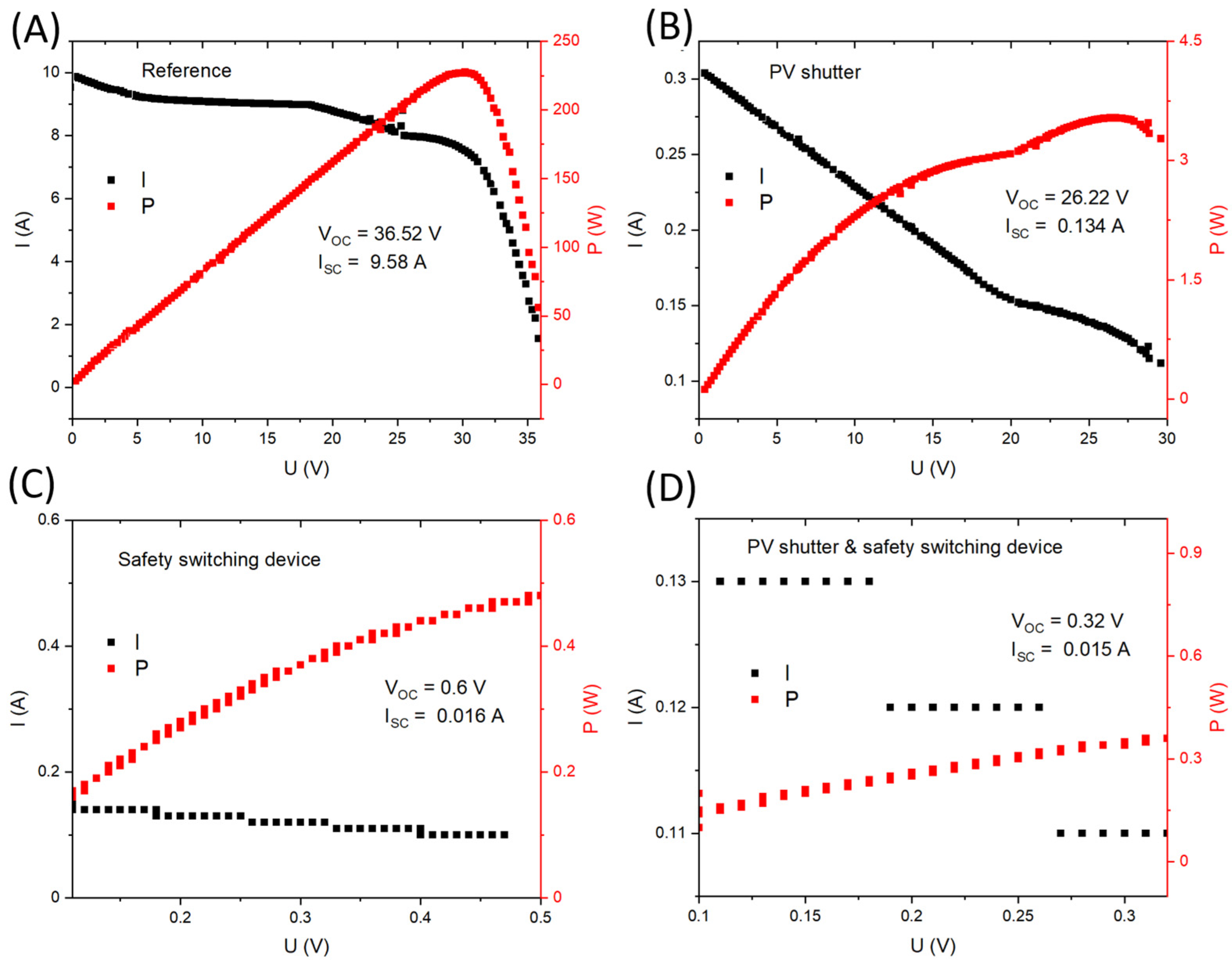
3.1. Numerical Simulations of the Touch Current

The problem of touch current (It) generated by PV systems [46] in emergency conditions is widely described in the literature [5,47,48]. Direct contact with damaged parts of PV installations or the use of conductive tools and extinguishing agents (e.g., water) when extinguishing a fire in a PV installation may cause permanent injuries or even death due to electric shock. A dangerous situation can also occur during periodic services of that kind of power generator, because PV modules in normal conditions continuously generate electric current. For this reason, it was decided to estimate the effectiveness of the proposed comprehensive system for protection of PV installations in limiting of the touch current. For this purpose, the MATLAB Simulink R2024b software [49] was used to simulate a PV installation based on a series connection of PV modules (Swiss Solar IBEX 120 MHC_EIGER 450 W, Zug, Switzerland). In the investigated case, the voltage of a single module was equal at Um = 49 V and the voltage of string was defined by number of PV modules (n) following the equation Us = Umn, where n = {1, 2, 4, 8, 12, 16, 20}. The results of performed numerical simulations are presented in Figure 5.
In the case of the reference, a typical linear dependence can be observed between It and the resultant resistance of a shocked person (sum body, shoe, and clothing resistance). It should be mentioned that It increases with the Us, whilst higher resistances corresponds to decreases of this parameter. The typical resistance of human body is 1 kΩ [50]; thus, for this case and Us = 49 V, the value of It is close to 50 mA, which is lower than the safety limit defined in IEC 60479-1:2018 standard as Is = 70 mA. Nonetheless, it is worth noting that for Us = 196 V (four series-connected PV modules), It is about 200 mA, which can be potentially dangerous due to ventricular fibrillation. The impact of the proposed PV shutter was simulated by reducing the value of irradiation to 15 W/m2, which is depicted in Figure 5B. The use of the shutter reduces the current output of the DC source, i.e., the PV installation. Consequently, this limits the maximum value of It to approximately 100 mA, regardless of the voltage Us. Thanks to this, in order to avoid the negative consequences of electric shock, it is sufficient to use personal protective equipment (e.g., footwear) that increases the overall resistance of a person to approximately 20 kΩ. The results presented in Figure 5C confirm the validity of using the safety switching device as a means of protection against electric shock. The reduction in the output voltage of a PV panel (or a chain of such panels) causes the expected shock current to drop almost to zero. The proposed apparatus effectively reduces the voltage regardless of the number of PV modules connected in series, which confirms its usefulness in real-world PV installations. Similar results were obtained in the case of the comprehensive safety system (Figure 5D). However, it should be noted that the synergy of both components of this system results in increased reliability and a reduction in the short-circuit current flowing through the abovementioned apparatus. Additionally, the use of the PV shutter provides extra protection against the spread of fire, as simulated in the following subsection.

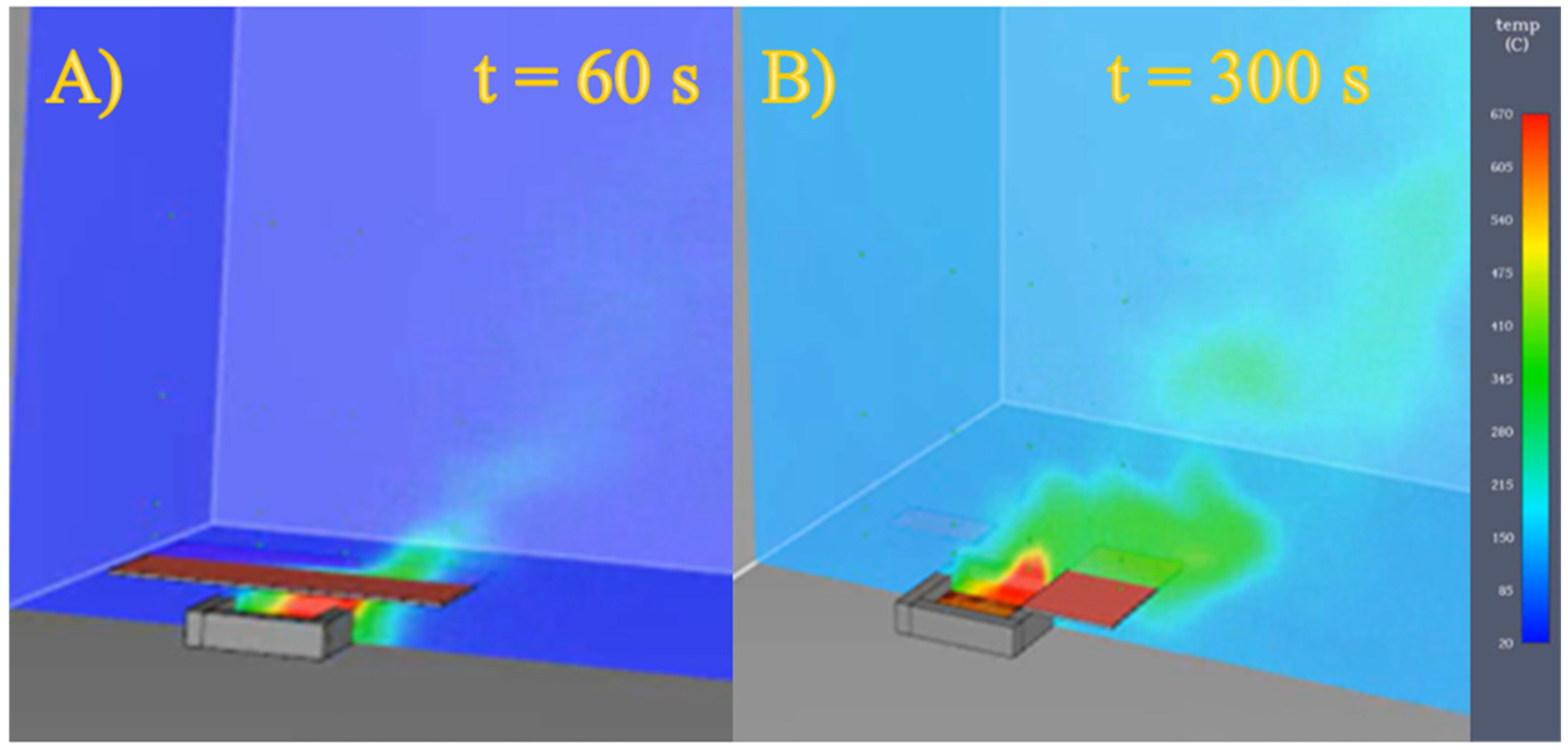
3.2. Numerical Simulations of the Fire Protection

The impact of the fire shutter on improving safety was estimated based on numerical simulations representing possible cases related to the burning of photovoltaic panels. For this purpose, specialist PyroSim 2020.1.0324 software was used to simulate fire development, which uses the computational fluid dynamics (CFD) method to model the flow of gases generated during combustion. The case with and without the fire shutter was analyzed, assuming the Swiss Solar IBEX 120 MHC_EIGER 450 W PV panel used in previous simulations as the research object. Figure 6 shows the temperature distribution around the unprotected PV module after 60 s and 300 s from the start of the fire. It is clearly visible that the flame quickly covers the entire PV panel, leading to its destruction. The temperature values increased approximately linearly with the duration of the combustion process. The highest temperature value was recorded directly above the central part of the PV panel and was Tmax = 550 °C after t = 300 s.
In the case of burning PV panel with a shutter, as shown in Figure 7, the temperature extreme also occurred directly above its surface; however, the highest recorded temperature did not exceed Tmax = 250 °C. In addition, the use of the mentioned shutter significantly reduced the flame height. The numerical simulations performed clearly indicate the positive effect of the shutter during the PV installation fire.

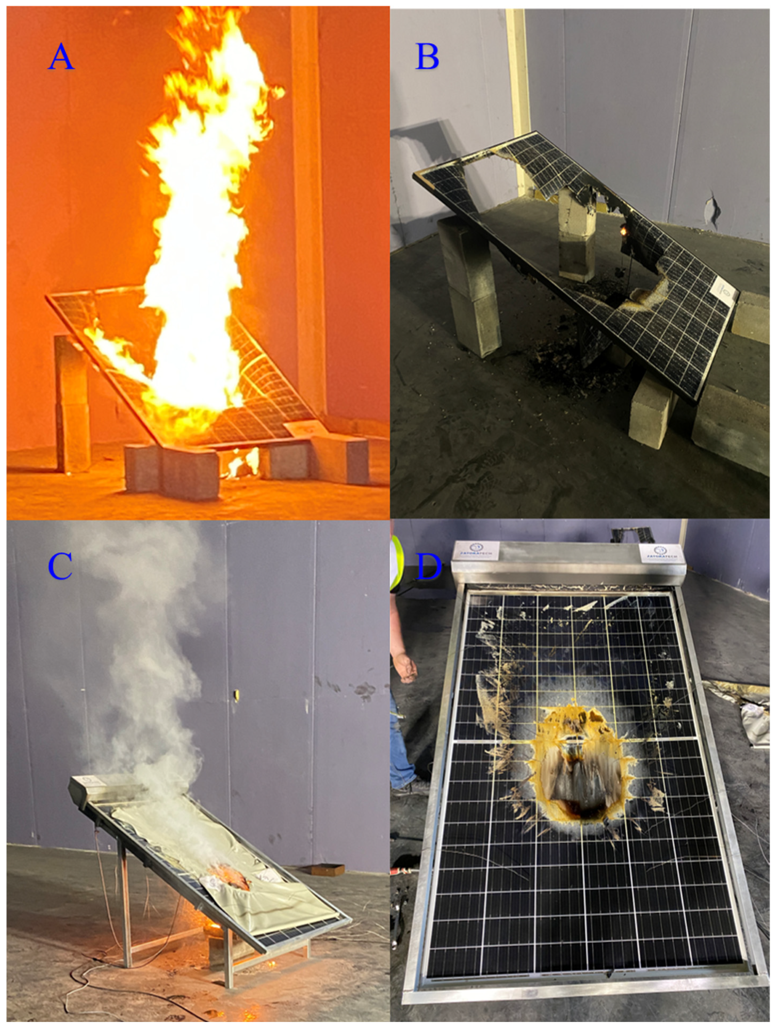
4. Experimental Verification of the Adopted Solutions

The actual effectiveness of the comprehensive safety system for PV installations was verified by conducting tests on a PV panel equipped with the mentioned system and its individual components. For comparison purposes, measurements were also taken on a reference panel with identical parameters, situated under the same lighting conditions. In order to investigate the impact of the abovementioned devices on the PV panel generation process, the I(U) characteristics were measured employing a PROVA 1011 analyzer equipped with an irradiance and temperature sensor. The panels used for the tests were manufactured by Solar Swiss and their basic parameters are gathered in Table 1 [51].
The obtained results, including the I(U) and P(U) graphs, are depicted in Figure 8. It can be observed that covering the panel surface with the shatter results in a significant reduction in short-circuit current (approximately 70 times), consequently limiting the power of the generated electric current (see Figure 8B). It is important to note the effect of shading the panel on the generation of output voltage—which continues even when the panel is completely covered. The influence of the safety switching device on the current and power dependence on the voltage of the PV panel is presented in Figure 8C. The attached characteristic shows a large (about 600 times) reduction in short-circuit current after the apparatus is activated. This device also causes the panel output power to drop by over 60 times to 0.5 Wp. The combined effect of the switching device and the shutter is shown in Figure 8D. In this case, it can be stated that the interaction of both systems causes an even greater decrease in the output voltage than the switching apparatus alone. The measured short-circuit currents in both cases are almost identical; however, the recorded peak power value is meaningfully lower. The observed step-like nature of the I(U) curve is most likely an artifact related to the measurement setup. By analyzing these figures, it is clear that the combination of the mentioned apparatus and the fire protection shade significantly enhances safety by drastically reducing both the current and voltage outputs of the PV panel, thus limiting the potential electrical hazards.
The experiments described above were supplemented by a study of the effect of the roller shutter on the spread of fire during the burning of a PV module. Solar Swiss model IBEX 120 MHC_EIGER PV panels were again used as the test object. Initially, reference tests were conducted on a PV panel without any protective measures. The burning procedure was carried out following the guidelines for the burning brand method, as described in the standard IEC 61730-2 [52]. The various stages of the experiment are illustrated in Figure 9A,B. Using ImageJ 1.54i image analysis software [53], it was estimated that approximately 70% of the panel surface was damaged. The experiment was then repeated for a PV panel covered with the protective screen. The results of this test are shown in Figure 9C,D. In this case, the damage to the panel was significantly reduced, affecting only about 15% of its total surface area. Furthermore, the screen significantly limited the height of the flame column, which is crucial for preventing the spread of fire. The obtained results confirmed the correctness of the numerical simulations presented in Section 2.

5. Economic Analysis of the Proposed System

In the context of the potential widespread adoption of the proposed comprehensive safety system for PV installations, the cost-effectiveness of the investment in this solution is of paramount importance. If the proposed solution turned out to be too expensive, its use would be economically unjustifiable. To assess the cost-effectiveness of the investment in the proposed system, relevant calculations were carried out using the specialized software program BlueSol 4.0 [54], which is designed for the comprehensive planning of solar systems. The advantage of this software is that it supports project planning from technical, optimization, and economic perspectives, allowing for an accurate representation of a given PV installation based on an integrated CAD system, a 3D visualization module, and real data on solar radiation and terrain topography. To conduct a thorough evaluation of the cost-effectiveness of the proposed safety system, specific assumptions and parameters were established for calculations. The PV installation in question is based on Solar Swiss photovoltaic modules, which were used in experiments described in Section 4. Each PV module is equipped with a shutter, and the switching apparatus secures individual strings of modules. The average cost of 1 Wp of a photovoltaic installation was determined based on [55] as USD 3, while costs of the shutter and the switching apparatus (in the case of long-run production) should be equal to USD 100 and 50, respectively. BlueSol software was utilized to design PV installations for various types of buildings, including a single-family house, a multi-family residential building, a school, and a photovoltaic farm. To ensure the reliability of the results, actual buildings located in northern Poland were selected. The software facilitated the selection of the optimal number of panels for each installation and proposed a method for connecting them into strings. Based on this, the maximum power output of the PV installation for each building was estimated, as well as the costs of installation. Subsequently, assuming the abovementioned safety system, the increase in installation costs associated with the use of PV shutters and switching apparatuses was calculated and the results are gathered in Table 2.
Analyzing the data presented in Table 2, it can be stated that the use of the proposed security system is associated with an increase in investment costs by approximately 25% of the value of the PV installation itself. The average cost of the described protection system can be estimated at about 740 USD/kWp. The given value may seem significant, but it is worth comparing it with the costs of installing other BoS elements, which were mentioned in the introduction to this article. Table 3 presents the cost of installation in terms of the generating capacity of the PV installation for selected systems described in the literature.
Comparing the collected data, it can be seen that the proposed comprehensive security system is cheaper than the AI-based solution proposed by F. Brito et al. [41]. Although PV shutters and safety switching devices are a significant cost-generating element in the case of investment in a PV installation, it is worth considering their use. When designing a PV installation on a building, it is necessary to estimate the potential losses associated with this investment (e.g., increased fire risk) and take appropriate preventive measures [10,15]. The conducted investigations clearly indicate that the mentioned system is characterized by high effectiveness in preventing the occurrence of fires and significantly affects the minimization of losses if such an event occurs. It can be especially important in the case of buildings of great historical and cultural value or facilities where many people can stay at the same time (e.g., large-scale stores, hospitals).

6. Conclusions

The comprehensive PV installation security system presented in this article is an innovative solution that decreases the risks associated with PV installations. The aforementioned system consists of roller shutters mounted on PV panels, which in an emergency limit irradiance and reduce fire propagation, and a safety switching device that allows for short-circuiting of individual PV panels and disconnection of the DC chain. The synergy of the presented solutions leads to a reduction in the voltage and current intensity generated by the PV system, which can be of great importance both in operating and emergency conditions. Both numerical simulations and conducted experimental studies confirm the effectiveness of the developed system. A roughly 70 times decrease in generated current was observed after application of the PV shutter, whilst the switching apparatus led to a drop in output voltage to almost zero. Moreover, the use of a PV shutter not only reduced the damage to PV modules (approximately 4.6 times lower destroyed area) but also resulted in a significant reduction of flame height, which may be important from the point of view of the spread of fire. Based on the calculations performed, it should also be assumed that the use of this system is justified from an economic point of view. Further investigations in this area should focus on combination of PV modules linked with an automatic self-cleaning mechanism similar to those described in a previous article [25]. This would lead to obtaining a multifunctional system that provides safety exploitation for PV installations and maintains high efficiency.

Author Contributions

K.S.: Investigation, Writing–original draft, Visualization. M.O.: Writing—review and editing, Investigation, Supervision, Data curation. M.A.: Writing—review and editing, Supervision. M.N.: Methodology, Investigation, Conceptualization, Formal analysis, Visualization. L.S.L.: Writing—original draft, Methodology, Investigation, Conceptualization, Visualization, Data curation, Formal analysis. K.B.: Writing—review and editing, Data curation; J.G.: Writing—review and editing, Methodology, Investigation, Validation, Visualization. All authors have read and agreed to the published version of the manuscript.

Funding

This research received no external funding.

Data Availability Statement

The original contributions presented in the study are included in the article, further inquiries can be directed to the corresponding author.

Acknowledgments

We are thankful to Michał Walkosz from the company STIGO for his help with numerical simulations in PyroSim 2020.1.0324.

Conflicts of Interest

The authors declare no conflict of interest.

Appendix A. Supplementary Data

The design of the safety switching device is illustrated in Figure A1. The device operates using a control signal, “Control_VGs”, which serves as the activation trigger for the safety system. The circuit incorporates two MOSFET transistors with different channel types: transistor Q1 is an n-type, while transistor Q2 is a p-type. Under normal operating conditions, Q1 remains in a conducting state, allowing for current flow, while Q2 stays off. However, if the “Control_VGs” signal is lost—such as in the event of wire burnout—the safety mechanism is triggered. This results in Q2 turning on, effectively short-circuiting the photovoltaic panel, while Q1 simultaneously turns off, preventing current flow to the system input. The device is built using MOSFET transistors carefully selected to ensure compatibility with both individual photovoltaic panels and series-connected module chains. This design enhances system safety by enabling automatic disconnection and current interruption in emergency scenarios.
Figure A1. A circuit diagram of a safety switching device for PV installations. In normal operating conditions, transistor Q1 is in the conduction state and Q2 is in the cut-off state. Voltage decay on the VG_s line causes both transistors to switch to the opposite state.
Energies 18 01749 g0a1

References

  1. Rynska, E. Review of PV Solar Energy Development 2011–2021 in Central European Countries. Energies 2022, 15, 8307. [Google Scholar] [CrossRef]
  2. Cader, J.; Olczak, P.; Koneczna, R. Regional dependencies of interest in the ‘My Electricity’ photovoltaic subsidy program in Poland. Polityka Energetyczna–Energy Policy J. 2021, 24, 97–116. [Google Scholar] [CrossRef]
  3. Cui, Y.; Zhu, J.; Meng, F.; Zoras, S.; McKechnie, J.; Chu, J. Energy assessment and economic sensitivity analysis of a grid-connected photovoltaic system. Renew. Energy 2020, 150, 101–115. [Google Scholar] [CrossRef]
  4. Sanchez-Sutil, F.; Hernández, J.C.; Tobajas, C. Overview of electrical protection requirements for integration of a smart DC node with bidirectional electric vehicle charging stations into existing AC and DC railway grids. Electr. Power Syst. Res. 2015, 122, 104–118. [Google Scholar] [CrossRef]
  5. HernÁndez, J.C.; Vidal, P.G. Guidelines for Protection Against Electric Shock in PV Generators. IEEE Trans. Energy Convers. 2009, 24, 274–282. [Google Scholar] [CrossRef]
  6. Czapp, S.; Swisulski, D. LabVIEW-based intelligent system of protection against electric shock for photovoltaic installations. In Proceedings of the 2017 52nd International Universities Power Engineering Conference (UPEC), Heraklion, Greece, 28–31 August 2017; pp. 1–6. [Google Scholar] [CrossRef]
  7. Pons, E.; Tommasini, R. Lightning protection of PV systems. In Proceedings of the 2013 4th International Youth Conference on Energy (IYCE), Siófok Hungary, 6–8 June 2013; pp. 1–5. [Google Scholar]
  8. Christodoulou, C.A.; Ekonomou, L.; Gonos, I.F.; Papanikolaou, N.P. Lightning protection of PV systems. Energy Syst. 2016, 7, 469–482. [Google Scholar]
  9. Fallah, N.; Gomes, C.; Ab Kadir, M.Z.A.; Nourirad, G.; Baojahmadi, M.; Ahmed, R.J. Lightning protection techniques for roof-top PV systems. In Proceedings of the 2013 IEEE 7th International Power Engineering and Optimization Conference (PEOCO), Langkawi, Malaysia, 3–4 June 2013; pp. 417–421. [Google Scholar]
  10. Litzbarski, L.; Olesz, M.; Seklecki, K.; Nowak, M. Ryzyko strat odgromowych a systemy fotowoltaiczne. Przeglad Elektrotechniczny 2023, 1, 295–297. [Google Scholar]
  11. MFalvo, C.; Capparella, S. Safety issues in PV systems: Design choices for a secure fault detection and for preventing fire risk. Case Stud. Fire Saf. 2015, 3, 1–16. [Google Scholar] [CrossRef]
  12. Mazziotti, L.; Cancelliere, P.; Paduano, G.; Setti, P.; Sassi, S. Fire risk related to the use of PV systems in building facades. MATEC Web Conf. 2016, 46, 5001. [Google Scholar] [CrossRef]
  13. Wu, Z.; Hu, Y.; Wen, J.X.; Zhou, F.; Ye, X. A Review for Solar Panel Fire Accident Prevention in Large-Scale PV Applications. IEEE Access 2020, 8, 132466–132480. [Google Scholar] [CrossRef]
  14. Seklecki, K.; Litzbarski, L.; Wójcik, K.; Cieślikowska, Z.; Włas, M.; Grochowski, J. Instalacje fotowoltaiczne w budownictwie wielorodzinnym. Przeglad Elektrotechniczny 2024, 2024, 81–83. [Google Scholar] [CrossRef]
  15. Litzbarski, L.S.; Seklecki, K.; Adamowicz, M.; Grochowski, J. PV installations and the safety of residential buildings. Inżynieria Bezpieczeństwa Obiektów Antropog. 2023, 4, 1–10. [Google Scholar]
  16. Ong, N.A.F.M.N.; Tohir, M.Z.M.; Mutlak, M.M.; Sadiq, M.A.; Omar, R.; Said, M.S.M. BowTie analysis of rooftop grid-connected photovoltaic systems. Process. Saf. Prog. 2022, 41, S106–S117. [Google Scholar] [CrossRef]
  17. Backstrom, R.; Dini, D. Firefighter safety and photovoltaic installations research project. In Proceedings of the Reliability of Photovoltaic Cells, Modules, Components, and Systems V, San Diego, CA, USA, 12–16 August 2012; pp. 78–92. [Google Scholar]
  18. Ramali, M.R.; Ong, N.A.F.M.N.; Said, M.S.M.; Yusoff, H.M.; Baharudin, M.R.; Tharima, A.F.; Akashah, F.W.; Tohir, M.Z.M. A Review on Safety Practices for Firefighters During Photovoltaic (PV) Fire. Fire Technol. 2023, 59, 247–270. [Google Scholar] [CrossRef] [PubMed]
  19. Young-chan, O.; Kawshalya, R.; Jin, P.; Lim, H. Study on Fire Breakout Prevention of Solar Power System. Int. J. Energy Environ. Econ. 2020, 26, 31. [Google Scholar]
  20. Cancelliere, P.; Puccia, V.; Longobardo, G.; Liciotti, C.; Cardinali, M. Behavior of the Electrical Parameters of PV Modules Subject to a Flame Ignition. In Proceedings of the 28th European Photovoltaic Solar Energy Conference and Exhibition, Paris, France, 30 September–4 October 2013. [Google Scholar]
  21. Kiryu, K.; Tanaka, T.; Seki, K.; Satou, K. Verification of arc discharge phenomenon and connection reliability. In Proceedings of the 2019 IEEE Third International Conference on DC Microgrids (ICDCM), Matsue, Japan, 20–23 May 2019; pp. 1–6. [Google Scholar] [CrossRef]
  22. Baumgartner, F. 5-Photovoltaic (PV) balance of system components: Basics, performance. In The Performance of Photovoltaic (PV) Systems; Pearsall, N., Ed.; Woodhead Publishing: Cambridge, UK, 2017; pp. 135–181. [Google Scholar] [CrossRef]
  23. Kobrin, B. Self-Cleaning Technologies for Solar Panels; n-Tech Research Publication: Glen Allen, VA, USA, 2018. [Google Scholar]
  24. Hossain, M.S.; Pandey, A.K.; Rahim, N.A.; Selvaraj, J.; Tyagi, V.V.; Islam, M.M. Self-cleaning assisted photovoltaic system with thermal energy storage: Design and performance evaluation. Sol. Energy 2020, 206, 487–498. [Google Scholar] [CrossRef]
  25. Khan, M.U.; Abbas, M.; Khan, M.M.; Kousar, A.; Alam, M.; Massoud, Y.; Jafri, S.H.M. Modeling and design of low-cost automatic self cleaning mechanism for standalone micro PV systems. Sustain. Energy Technol. Assess. 2021, 43, 100922. [Google Scholar] [CrossRef]
  26. Styszko, K.; Jaszczur, M.; Teneta, J.; Hassan, Q.; Burzyńska, P.; Marcinek, E.; Łopian, N.; Samek, L. An analysis of the dust deposition on solar photovoltaic modules. Environ. Sci. Pollut. Res. 2019, 26, 8393–8401. [Google Scholar] [CrossRef]
  27. Klugmann-Radziemska, E.; Rudnicka, M. The Analysis of Working Parameters Decrease in Photovoltaic Modules as a Result of Dust Deposition. Energies 2020, 13, 4138. [Google Scholar] [CrossRef]
  28. Litzbarski, L.; Olesz, M.; Seklecki, K. Measurement practice of photovoltaic installations leading to the determination of the actual technical condition; [Praktyka wykonywania pomiarów instalacji fotowoltaicznych prowadząca do określenia rzeczywistego stanu technicznego]. Przeglad Elektrotechniczny 2024, 2024, 84–86. [Google Scholar] [CrossRef]
  29. Simon, M.; Meyer, E.L. Detection and analysis of hot-spot formation in solar cells. Sol. Energy Mater. Sol. Cells 2010, 94, 106–113. [Google Scholar] [CrossRef]
  30. Rijvers, L.; Rindt, C.; de Keizer, C. Numerical Analysis of a Residential Energy System That Integrates Hybrid Solar Modules (PVT) with a Heat Pump. Energies 2022, 15, 96. [Google Scholar] [CrossRef]
  31. Ju, X.; Xu, C.; Liao, Z.; Du, X.; Wei, G.; Wang, Z.; Yang, Y. A review of concentrated photovoltaic-thermal (CPVT) hybrid solar systems with waste heat recovery (WHR). Sci. Bull. 2017, 62, 1388–1426. [Google Scholar] [CrossRef]
  32. Vittorini, D.; Castellucci, N.; Cipollone, R. Heat recovery potential and electrical performances in-field investigation on a hybrid PVT module. Appl. Energy 2017, 205, 44–56. [Google Scholar] [CrossRef]
  33. Dini, D.A.; Brazis, P.W.; Yen, K.-H. Development of Arc-Fault Circuit-Interrupter requirements for Photovoltaic systems. In Proceedings of the 2011 37th IEEE Photovoltaic Specialists Conference, Seattle, WA, USA, 19–24 June 2011; pp. 1790–1794. [Google Scholar]
  34. Ramos, F.; Neto, J.; Almeida, F.; Velázquez, S.; Lima, B. Compliance Analysis of Series Arc-fault in AFCI- Equipped Inverters in Accordance with IEC 63027. IEEE Lat. Am. Trans. 2024, 22, 761–770. [Google Scholar] [CrossRef]
  35. Bower, W.; Wiles, J. Investigation of ground-fault protection devices for photovoltaic power system applications. In Proceedings of the Conference Record of the Twenty-Eighth IEEE Photovoltaic Specialists Conference—2000 (Cat. No.00CH37036), Anchorage, AK, USA, 15–22 September 2000; pp. 1378–1383. [Google Scholar] [CrossRef]
  36. Zetawi, E.A.; Abdulhadi, E.O.; Shahroury, F.R.; Ahmad, H.H.; Akour, A. Components and Specification of Rapid Shutdown for Roof PV Systems. In Proceedings of the 2021 International Conference on Microelectronics (ICM), New Cairo City, Egypt, 19–22 December 2021; pp. 182–185. [Google Scholar] [CrossRef]
  37. Cordova, A.; Merz, C.; Bettenwort, G.; Hopf, M.; Knopf, H.; Laschinski, J. Rapid Shutdown with Panel Level Electronics—A suitable safety measure? In Proceedings of the 2017 IEEE 44th Photovoltaic Specialist Conference (PVSC), Washington, DC, USA, 25–30 June 2017; pp. 1965–1967. [Google Scholar] [CrossRef]
  38. Yalçın, C. Thermal imaging-based fault detection and energy efficiency analysis in a 1.6 MW photovoltaic system in Bağyurdu OIZ, Türkiye. Energy Storage Convers. 2025, 3, 1984. [Google Scholar] [CrossRef]
  39. Kandeal, A.; Elkadeem, M.; Thakur, A.K.; Abdelaziz, G.B.; Sathyamurthy, R.; Kabeel, A.; Yang, N.; Sharshir, S.W. Infrared thermography-based condition monitoring of solar photovoltaic systems: A mini review of recent advances. Sol. Energy 2021, 223, 33–43. [Google Scholar] [CrossRef]
  40. Ohuchi, T.; Ishikawa, N.; Kozawa, Y. Improvement of the fire-proofing and fire-resistance properties of PV modules for building’s exterior walls. In Proceedings of the Conference Record of the Twenty-Eighth IEEE Photovoltaic Specialists Conference—2000 (Cat. No.00CH37036), Anchorage, AK, USA, 15–22 September 2000; pp. 1533–1538. [Google Scholar] [CrossRef]
  41. Brito, M.d.F.; de Lima, L.C.; Batista, N.E. Batista Use of artificial intelligence in fire safety in solar photovoltaic systems. Res. Soc. Dev. 2023, 12, e106121444567. [Google Scholar] [CrossRef]
  42. Zhang, W.; Xu, P.; Wang, Y.; Li, D.; Liu, B. A DC arc detection method for photovoltaic (PV) systems. Results Eng. 2024, 21, 101807. [Google Scholar] [CrossRef]
  43. Kitai, A. Principles of Solar Cells, LEDs and Diodes: The Role of the PN Junction; John Wiley & Sons: Hoboken, NJ, USA, 2011. [Google Scholar]
  44. Abdelhady, S.; Abd-Elhady, M.S.; Fouad, M.M. An Understanding of the Operation of Silicon Photovoltaic Panels. Energy Procedia 2017, 113, 466–475. [Google Scholar] [CrossRef]
  45. Koźbiał, T. Generatory fotowoltaiczne w kontekście doboru elementów składowych oraz ochrony przeciwpożarowej. Przegląd Elektrotechniczny 2019, 96, 208–212. [Google Scholar] [CrossRef]
  46. IEC 60990; Methods of Measurement of Touch Current and Protective Conductor Current. British Standard: London, UK, 2016.
  47. Czapp, S.; Seklecki, K.; Litzbarski, L.; Olesz, M. Zagrożenie porażeniem podczas gaszenia pożaru w budynkach z fotowoltaicznymi źródłami energii. Przegląd Elektrotechniczny 2024, 66–72. [Google Scholar] [CrossRef]
  48. Czapp, S. Residual current devices in installations with PV energy sources. Przegląd Elektrotechniczny 2022, 98, 100–104. [Google Scholar]
  49. Tsai, H.-L.; Tu, C.-S.; Su, Y.-J. Development of generalized photovoltaic model using MATLAB/SIMULINK. In Proceedings of the World Congress on Engineering and Computer Science, San Francisco, CA, USA, 22–24 October 2008; pp. 1–6. [Google Scholar]
  50. Chinen, K.; Kinjo, I.; Zamami, A.; Irei, K.; Nagayama, K. New equivalent-electrical circuit model and a practical measurement method for human body impedance. Bio-Med. Mater. Eng. 2015, 26, S779–S786. [Google Scholar] [CrossRef]
  51. Solar Swiss. Available online: https://www.swissenergy-solar.ch/product/ibex-120mhc-eiger-450-460-full-black-en/ (accessed on 7 March 2025).
  52. IEC 61730-2; Photovoltaic (PV) Module Safety Qualification—Part 2: Requirements for Testing. IECEE: Geneva, Switzerland, 2023.
  53. Abràmoff, M.D.; Magalhães, P.J.; Ram, S.J. Image processing with ImageJ. Biophotonics Int. 2004, 11, 36–42. [Google Scholar]
  54. Kut, P.; Nowak, K. Design of Photovoltaic Systems using Computer Software. J. Ecol. Eng. 2019, 20, 72–78. [Google Scholar] [CrossRef]
  55. Forbes. Available online: https://www.forbes.com/home-improvement/solar/cost-of-solar-panels/ (accessed on 7 March 2025).
Figure 1. Number of publications about the issue of PV safety according to “Scopus” database.
Energies 18 01749 g001
Figure 2. Conception of PV blind limiting irradiation: normal conditions (A,C) and emergency ones (B,D).
Energies 18 01749 g002
Figure 3. PV blind limiting irradiation: a concept of a spring storage mechanism (A), a prototype of the blind (B).
Energies 18 01749 g003
Figure 4. The operating principle of a safety switching device in normal (A) and emergency (B) conditions.
Energies 18 01749 g004
Figure 5. Touch current generated by PV systems with different output voltages as a function of resistance: reference case (A), impact of PV shutter (B), impact of safety switching device (C), and impact of a comprehensive safety system (D).
Energies 18 01749 g005
Figure 6. The temperature distribution around the unprotected PV module after 60 s (A) and 300 s (B).
Energies 18 01749 g006
Figure 7. Temperature distribution around PV module with shutter after 60 s (A) and 300 s (B).
Energies 18 01749 g007
Figure 8. The I(U) and P(U) characteristics for the reference PV panel (A), the PV panel covered with the shutter (B), the PV panel connected to the safety switching device (C), and the PV panel protected by a comprehensive safety system (D).
Energies 18 01749 g008
Figure 9. Testing PV modules employing the burning brand method without (A,B) and with (C,D) the safety blind.
Energies 18 01749 g009
Table 1. Basic parameters of PV panels used in the investigations based on [51].
ParameterTitle 2
ModelIBEX 120
MHC_EIGER
Maximum power (Pmax)450 W
Open circuit voltage (Voc)49.03 V
Short-circuit current (Isc)11.04 A
Voltage at Pmax (Vmp)41.40 V
Current at Pmax (Imp)10.87 A
Module efficiency20.85%
Table 2. The impact of a comprehensive safety system on the total cost of PV installations.
Power of PV System (kWp)Number of PV PanelsNumber of StringsCost of PV Installation (USD)Cost of Safety System (USD)Total Cost (USD)
Single-family house1395239,000.009600.0048,600.00
Multi-family residential building412996123,000.0030,200.00153,200.00
School building322236960966,000.00239,900.001,205,900.00
PV farm112882931203,384,000.00835,300.004,219,300.00
Table 3. The cost of installation of selected BoS equipment.
BoS ComponentCost [$/Wp]Ref.
Robotic cleaning system10–12[23]
Arc fault circuit interrupter0.947[41]
Comprehensive safety system0.739This article
Automatic self-cleaning mechanism (ASCM)0.189[25]
CPVT system with active cooling and a storage tank0.067[31]
Disclaimer/Publisher’s Note: The statements, opinions and data contained in all publications are solely those of the individual author(s) and contributor(s) and not of MDPI and/or the editor(s). MDPI and/or the editor(s) disclaim responsibility for any injury to people or property resulting from any ideas, methods, instructions or products referred to in the content.

