Article

Research and Application of Drilling Fluid Cooling System for Dry Hot Rock

1
Institute of Exploration Techniques, Chinese Academy of Geological Sciences, Langfang 065000, China
2
School of Engineering and Technology, China University of Geosciences (Beijing), Beijing 100083, China
*
Author to whom correspondence should be addressed.
Energies 2025, 18(7), 1736; https://doi.org/10.3390/en18071736
Submission received: 9 March 2025 / Revised: 24 March 2025 / Accepted: 27 March 2025 / Published: 31 March 2025

Abstract

:
The drilling fluid cooling system is a key technology for reducing wellbore temperatures, improving the working environment of downhole equipment, and ensuring safe and efficient drilling in high-temperature wells. Based on the existing drilling fluid cooling system, this article designs and develops a closed drilling fluid cooling system according to the working environment and cooling requirements of the GH-02 dry hot rock trial production well in the Gonghe Basin, Qinghai Province. The system mainly includes a cascade cooling module, a convective heat exchange module, and a monitoring and control module. Based on the formation conditions and drilling design of the GH-02 well, a transient temperature prediction model for wellbore circulation is established to provide a basis for the design of the cooling system. Under the conditions of a drilling fluid displacement of 30 L/s and a bottomhole circulation temperature not exceeding 105 °C, the maximum allowable inlet temperature of the drilling fluid is 55.6 °C, and the outlet temperature of the drilling fluid is 69.2 °C. The heat exchange of the drilling fluid circulation is not less than 1785 kW. Considering the heat transfer efficiency and reserve coefficient, the heat transfer area of the spiral plate heat exchanger calculated using the average temperature difference method is not less than 75 m2. By applying this drilling fluid cooling system in the 3055 m~4013 m section of well GH-02, the inlet temperature is controlled at 45 °C~55 °C, and the measured bottomhole circulation temperature remains below 105 °C. After adopting the drilling fluid cooling system, the performance of the drilling fluid is stable during the drilling process, downhole tools such as the drill bits, screws, and MWD work normally, and the failure rate of the mud pump and logging instruments is significantly reduced. The drilling fluid cooling system effectively maintains the safe and efficient operation of the drilling system, which has been promoted and applied in shale oil wells in Dagang Oilfield.

1. Introduction

The majority of geothermal energy in the world exists in formations that are buried thousands of meters deep, have temperatures exceeding 200 °C, and do not contain water or only contain a small amount of water. These are what people call hot dry rock (HDR) geothermal resources [1]. As a renewable carbon-free clean energy source, dry hot rock geothermal resources have outstanding advantages such as large reserves, wide distribution, and good thermal continuity. Meanwhile, HDR is also internationally recognized as a strategic alternative energy with good development prospects [2,3,4]. In order to promote the commercial development of hot dry rock in China, the China Geological Survey organized relevant organizations to implement a hot dry rock trial production and power generation project in the Gonghe Basin of Qinghai Province from 2019 to 2022. Currently, multiple directional wells with design depths exceeding 4000 m and bottomhole temperatures of 210 °C have been deployed for trial production [5]. The high-temperature environment underground brings high risks and high costs to drilling operations, specifically manifested as follows: (1) As the temperature of the drilling fluid increases, drilling operators may suffer from high-temperature burns; (2) The rubber seals of the well control equipment face the risk of high-temperature failure [6]; (3) The accelerated degradation of the drilling fluid treatment agents makes the mud performance prone to failure, further causing instability of the wellbore and posing potential accidents. At the same time, it also increases the difficulty and cost of drilling fluid maintenance; (4) The accelerated wear of the surface equipment, especially the pistons and cylinder liners of the mud pumps, under high-temperature conditions increases the non-production time significantly, thereby reducing the continuity of the drilling operations; (5) The high temperature underground poses extreme challenges to the temperature resistance performance of downhole tools and instruments such as drill bits, screws, MWD, LWD, RSS, etc. This can lead to unstable instrument signals, shorten the lifespans of the downhole tools, and significantly increase the drilling cycles and costs [7].
To address the issue of high temperatures at the downhole, the first consideration is to apply high-temperature resistant materials and insulation technology to the production and manufacturing of the drilling fluids and downhole tools in order to improve the temperature resistance of the drilling system itself, as in the 300 °C directional drilling system developed by Baker Hughes [8].
Secondly, another consideration can be to control the wellbore temperature within an acceptable temperature range, thereby improving the working environment of the drilling fluid and downhole equipment. There are currently several ways to use this method: (1) Natural cooling: increasing the volume of the drilling fluid cooling pool or the length of the circulation pipeline enables sufficient heat exchange between the drilling fluid and the natural environment; (2) Surface cooling of drilling fluid: generally, a drilling fluid cooling system is used to actively cool the drilling fluid and reduce the temperature of the drilling fluid entering the wellbore [9,10]; (3) Thermal insulated drill pipe: using a pipe string with a thermal insulation function reduces the heat loss during the flow of the drilling fluid along the pipe string, so that the drilling fluid still has a low temperature after reaching the bottom of the wellbore in order to ensure the cooling demand for the downhole drilling equipment [11,12]; (4) Phase change cooling of drilling fluid material: adding a certain amount of phase change material to the drilling fluid uses the latent heat of the phase change to achieve the purpose of cooling [13]. In engineering practice, the cooling capacity of the natural environment is limited except in winter, and the thermal insulation drill pipe and drilling fluid phase change cooling technology have not yet been commercially applied on a large scale. Therefore, the surface drilling fluid cooling system has become the most direct and effective means to reduce the wellbore circulation temperature.
The research on drilling fluid cooling technology began with the development of the Geysers geothermal field in northern San Francisco, CA, USA. Currently, Drill Cool, M-I SWACO, and NOV in the United States, FPT in Singapore, and TES in the Netherlands have successively developed series of drilling fluid cooling equipment which have been widely used in DHR development. Drill Cool has developed three series of products: the FRESHWATER GEO-COLLER series (Figure 1) uses evaporative cooling for direct cooling, which is consistent with the principle of closed cooling towers; the DRY AIR GEO-COLLER series uses a compressor to forcibly cool the air and employs a gas–liquid plate heat exchanger [14]; the GCFX GEO-CHILLER series uses an air-cooled chiller to mechanically cool the cooling medium, and achieves convective heat exchange between the cooling medium and drilling fluid through a wide gap plate heat exchanger. The TUNDRA from NOV Corporation™ MAX Mud Chiller cooling equipment (Figure 2) adopts both air-cooled mechanical refrigeration and liquid–liquid heat exchange refrigeration, and the heat exchanger uses titanium plate heat exchangers, which can achieve one-click operation and automated operation.
China’s research on drilling fluid cooling technology and equipment began relatively late. Prior to 2018, Jilin University and the Institute of Exploration Techniques developed various specifications and models of drilling fluid and mud cooling systems, including coaxial casing cooling systems and finned tube cooling systems. These systems were able to dynamically stabilize the inlet temperature of the drilling fluid below 0 °C, and they effectively supported the exploration and trial production of the terrestrial natural gas hydrate layer, which accumulates theoretical and practical experience for the development of high-temperature drilling fluid cooling equipment [15]. In recent years, with the continuous increase in drilling depth and the widespread application of tools and instruments such as LWD, VDS, and RSS, the oil and gas drilling and geothermal drilling industries have also developed and applied high-temperature drilling fluid cooling equipment. Baoji Petroleum Machinery Corporation has developed the ZLQ030-75 high-temperature drilling fluid cooling device, which uses a square counter-current open cooling tower as the cooling medium’s heat dissipation component and a stainless steel flat plate heat exchanger. It has the characteristics of a modular structure design and constant-temperature automatic control. This set of equipment has been applied on-site in three shale oil horizontal wells in Dagang Oilfield (Figure 3), and can reduce the inlet temperature of the drilling fluid from 52–54 °C to around 35 °C [16,17,18]. The JW-GCY-1 drilling fluid cooling system developed by the China Petroleum Engineering Technology Research Institute adopts heat pipe exchanger technology and cooling tower evaporation heat dissipation technology, which can reduce the inlet temperature of the drilling fluid by about 30 °C and the bottomhole temperature by 5–8 °C [19].
After more than 40 years of development, various cooling methods, heat exchange modes, and structural forms of the drilling fluid cooling system have been developed in the industry. At the same time, the degree of efficiency, automation, modularity, and integration is increasing. Drilling fluid cooling equipment has been widely used in the construction of HTHP (high-temperature and high-pressure) wells and geothermal wells, and has achieved ideal application results. Based on a thorough investigation of the current development status of the drilling fluid cooling system, this article designs and develops a drilling fluid cooling system according to the cooling requirements of the well GH-02 drilling operation conducted by the Exploration Technology Research Institute of the Chinese Academy of Geological Sciences in the Gonghe Basin, Qinghai, and this system has achieved ideal application results in the Gonghe dry hot rock trial production well in Qinghai.

2. Method of Design of Drilling Fluid Cooling System for GH-02 Well

2.1. Overall Design of System Components

Based on the working environment of the equipment, this article designs a drilling fluid cooling system based on a heat exchanger with evaporative cooling as the main method, air cooling as the auxiliary method, and mechanical refrigeration to increase efficiency, as shown in Figure 4. The system mainly includes a coolant cooling module, a convective heat exchange module, a monitoring and control module, etc.
The coolant cooling module mainly includes cooling tower, chiller, circulating pump units, water tanks, etc. The coolant can be selected from the water or ethylene glycol aqueous solutions commonly used in industrial refrigeration according to the ambient temperature. Meanwhile, using a counter-current closed cooling tower can effectively reduce the evaporation loss of cooling water. The cooling module adopts a cascade cooling mode, mainly based on evaporative cooling of the cooling tower, which can meet conventional needs. If the ambient temperature is low, the spray pump of the cooling tower can be turned off, and the air-cooling mode can be used. If the ambient temperature is too high and the evaporative cooling capacity is insufficient or a lower inlet temperature is required, the mechanical refrigeration of the chiller can be turned on for secondary cooling.
The convective heat transfer module mainly includes the heat exchanger, coolant circulation pumps, drilling fluid circulation pumps, etc. The heat exchanger is the core component for achieving full-process counter-current heat transfer between the drilling fluid and the coolant. After comprehensive comparative research, a stainless steel spiral plate heat exchanger (structural principle shown in Figure 5) is selected. This type of heat exchanger has the advantages of a large heat transfer area per unit volume and high heat transfer efficiency, and the drilling fluid is not prone to adhesion and scaling. At the same time, the stainless steel material has good corrosion resistance to the organic salt drilling fluid, which can ensure long-term efficient heat transfer.
The monitoring and control module mainly includes temperature and flow monitoring units, coolant cooling control units, and convective heat transfer control units. The temperature and flow monitoring unit mainly collects and records key parameters such as the temperature and flow of the coolant and drilling fluid to monitor the operating status of the cooling system and the efficiency of the heat exchanger. The temperature control unit can automatically switch between cooling modes such as air cooling, evaporative cooling, and mechanical cooling based on the set coolant temperature and ambient temperature, achieving efficient and low-consumption cooling. For example, under normal working conditions (an ambient temperature of approximately 0–35 °C), the system defaults to evaporative cooling; when the ambient temperature is 0 °C, the system automatically chooses air cooling to meet the cooling needs of the drilling fluid, but if the ambient temperature is too high, such as exceeding 35 °C, the system activates mechanical refrigeration to increase efficiency. The convective heat transfer control unit can control the start of the coolant circulation pump and drilling fluid circulation pump based on the set temperature of the drilling fluid entering the well, dynamically stabilizing the temperature of the drilling fluid at a low temperature. The entire operation of the drilling fluid cooling system can achieve one-click constant-temperature automation control, without the need for manual operation.

2.2. Calculation of Circulating Heating Power of Drilling Fluid

The temperature change of the drilling fluid in the wellbore is dynamic, so in the design process of the drilling fluid cooling system, a numerical simulation method is first used to predict the temperature of the wellbore. To simplify the numerical modeling process, the following assumptions are first made [20]:
(1)
The drilling fluid is an incompressible and uniform medium, and its thermal and physical parameters do not change with temperature during the circulation process;
(2)
The surrounding rock is an isotropic homogeneous medium, and its thermal and physical properties do not change with temperature or pressure;
(3)
Ignoring the radial temperature gradient of the drilling fluid inside the wellbore, the temperature of the drilling fluid inside the wellbore is continuous in the z-direction;
(4)
Only the heat transfer in the r-direction of the surrounding rock is considered.
For vertical wells with no severe leakage in the formation and no long-term shutdown of the pumps, according to the law of conservation of energy and the Fourier heat transfer equation, the heat transfer equation between the drilling fluid and the surrounding rock in the wellbore is established.
The heat transfer equation of the drilling fluid in the drill pipe is as follows:
c 1 ρ 1 A p T p t = v p c 1 ρ 1 A p T p t + U p a T a T p
The heat transfer equation of the drilling fluid in the annulus is as follows:
c 1 ρ 1 A a T a t = v a c 1 ρ 1 A a T a t + U p a T p T a + U a r T f T a
The heat transfer equation of the surrounding rock is as follows:
c r ρ r T r t = r λ r T r r + 1 r λ r T r r
In Equations (1)–(3), ρf and ρr are the density of the drilling fluid and the surrounding rock, respectively, g/m3; Cf and Cr are the specific heat of the drilling fluid and the surrounding rock, respectively, J/(kg·°C); Tp and Ta are the temperatures of the drilling fluid in the drill pipe and in the annulus, respectively, °C; Tr is the temperature of formation, °C; Ap and Aa are the area of the inner cavity of the drill pipe and the annulus, respectively, m2; vp and va are the velocity of the flow of drilling fluid in the drill pipe and the annulus, respectively, m/s; Upa is the total heat transfer coefficient between the drilling fluid on the inner and outer walls of the drill pipe, W/(m·°C); Uar is the total heat transfer coefficient between the annular drilling fluid and the surrounding rock, W/(m·°C); λr is the thermal conductivity of the surrounding rock, W/(m·°C); r and z are the radial and axial dimensions of the wellbore, respectively, m; and t is the time, s.
The calculation method for the total heat transfer coefficient can be based on the formulas provided in the references [21]:
U p a 1 = 1 π d p h p + 1 2 π λ p ln D p d p + 1 π D p h a
U a r 1 = 1 π D a h a + i = 1 n 1 2 π λ c ln D c d c + i = 1 m 1 2 π λ c e m ln D c e m d c e m
In Equations (4) and (5), dp and Dp are the inner and outer diameters of the drill pipe, respectively, m; Da is the outer diameter of annulus, m; dc and Dc are the inner and outer diameters of the tubing, respectively, m; dcem and Dcem are the inner and outer diameters of the cement sheath, respectively, m; λp, λc, and λcem are the thermal conductivity coefficients of the drill pipe, casing, and cement sheath, respectively, W/(m·°C); and hp and ha are the convective heat transfer coefficients of the drilling fluid in the drill pipe and the annulus, respectively, W/(m2·°C).
The design depth of the GH-02 trial production well is about 4000 m, and the design of the wellbore structure is shown in Table 1.
By logging other dry hot rock trial wells in the Gonghe Basin of Qinghai Province, the geotemperature distribution in the Gonghe Basin area is shown in Figure 6.
Using the PDE module of COMSOL for numerical modeling and the geometric model and mesh as shown in Figure 7, the geometric model is divided into a total of 250 × 75 = 17,850 grids. In this model, the following is true:
  • When only considering the heat transfer in the r-direction, this means that there is no heat flux at the upper and lower boundaries of the geometric model, and therefore the upper and lower boundaries are adiabatic boundaries;
  • The temperature of the surrounding rock far away from the wellbore has not been disturbed, which means that the right boundary temperature of the geometric model is still equal to the initial geotemperature;
  • The left boundary is a coupled thermal boundary. This indicates that the left boundary represents both the temperature field of the drilling fluid inside the wellbore (Tp and Ta) and the temperature field of the surrounding rock boundary (Tr). The heat transfer between Tp, Ta, and Tr is determined by the total heat transfer coefficient and the temperature difference;
  • The wellhead drilling fluid is injected at a certain temperature. At the bottom of the well, the temperature in the drill pipe is equal to the temperature of the annulus.
  • The initial values of all temperature physical fields are equal to the initial geotemperature.
The MWD/LWD instrument used has a temperature resistance of 150 °C. At the same time, considering the static heating of the drilling fluid during the mud pump shutdown period, 30% of the heating space is reserved. Therefore, the design is based on the bottomhole circulation temperature not exceeding 105 °C. Based on the drilling technology, the design displacement of the high-temperature well section is 30 L/s so that both the rotation speed of the screw and the upward movement of rock debris can be ensured. Setting the calculation time step to 0.25 h, after using COMSOL Multiphysics 6.0 for numerical solution, the temperature distribution of the drilling fluid in the wellbore after stable circulation at different inlet temperatures can be seen in Figure 8. The bottomhole temperature and outlet temperature after stable circulation when the drilling fluid inlet temperature ranges from 40 °C to 60 °C can be seen in Figure 9. It can be seen that when the circulating temperature of the drilling fluid at the bottom of the well is 105 °C, the maximum allowable inlet temperature is 55.6 °C, the outlet temperature is 69.2 °C, and the temperature difference between the inlet and outlet is 13.6 °C.
The heating power of the drilling fluid wellbore circulation is calculated according to Equation (6):
W 1 = c 1 ρ 1 Q 1 Δ t 1
In Equation (6), W1′ is the heating power of the drilling fluid wellbore circulation, kW; Q1′ is the flow rate of the drilling fluid, L/s; and Δt1′ is the temperature difference of the drilling fluid outlet and inlet, °C.
According to the drilling design, a composite organic salt drilling fluid system is used in the high-temperature wellbore section, and its thermal and physical parameters are shown in Table 2. By substituting the relevant parameters into Equation (6), W1′ = 1785 kW.

2.3. Calculation of Heat Exchange Area of Heat Exchanger

In fact, since the numerical model does not consider the pump shutdown process during drilling and tripping, the calculated drilling fluid temperature results of the model should be smaller than the actual logging values. Therefore, a certain amount of redundancy needs to be retained when designing the key parameters of the drilling fluid cooling system. At the same time, according to the standards of China’s oil and gas drilling industry and considering the more severe high-temperature environment, 50% of the reserve power is reserved (taking a safety factor of 1.5), so the actual required drilling fluid cooling power is 2678 kW. To meet the cooling requirements of the cold and hot mixing of drilling fluid, the circulating flow rate of the drilling fluid is generally selected as 80% of the drilling displacement, which is 24 L/s. The inlet temperature of the heat exchanger drilling fluid can be calculated based on the outlet temperature of the drilling fluid at 69.2 °C, and the outlet temperature of the heat exchanger drilling fluid can be calculated as 48.8 °C. Considering the spray-cooling mode, the working area environment temperature of 35 °C and a humidity of 50% are selected for calculation, and the cooling limit of the refrigerant is equal to the wet bulb temperature of 26.15 °C. Conservatively calculated, the inlet temperature of the heat exchanger refrigerant is taken as 28.0 °C; therefore, the outlet temperature of the heat exchanger refrigerant can be obtained as 36.0 °C. The thickness of the heat exchanger plate δ = 4 mm, and the thermal conductivity coefficient of the plate λ = 16.2 W/(m·°C). The basic parameters for calculating the heat transfer areas of other heat exchangers are shown in Table 2.
Using the average temperature difference method to design and calculate the spiral plate heat exchanger, the steps are as follows:
(1) Equivalent diameter of circulation channel De:
Generally, the flow velocity of the medium in the channel of a spiral plate heat exchanger is 0.8 m/s to 2 m/s. To avoid scaling of the drilling fluid, a higher circulation flow rate of 2 m/s is selected for the calculation. The equivalent diameter De can be calculated by Equation (7):
D e = 4 Q 1 π v 1 = 174.85 mm
(2) Average temperature difference of heat exchange plates ΔTm:
Δ T m = T 11 T 22 T 12 T 21 ln T 11 T 22 ln T 12 T 21 = 54.6   ° C
(3) Reynolds number Re, Planck constant Pr, and Nusselt number Nu:
Re 1 , 2 = v 1 , 2 D e γ 1 , 2 = 3.1 × 10 4 Re 1 6.4 × 10 4 Re 2
Pr 1 , 2 = μ 1 , 2 c 1 , 2 λ 1 , 2 = 78.60 Pr 1 7.19 Pr 2
Nu 1 , 2 = 0.023 × Re 1 , 2 n Pr 1 , 2 m
In Equation (11), n = 0.8; the drilling fluid is cooled by the refrigerant, and therefore, m = 0.3 is taken for drilling fluid and m = 0.4 is taken for refrigerant. It can be calculated that Nu1 = 333.78 and Nu2 = 2236.95.
(4) Convection heat transfer coefficient h, heat transfer coefficient K, and heat transfer area A:
h 1 , 2 = λ 1 , 2 Nu 1 , 2 D e
K = 1 1 h 1 + δ λ + 1 h 2
A = 1.5 × W 1 K Δ t m
By Equations (12)–(14), the heat exchange area A can be obtained as 60 m2; according to the regulations for the use of heat exchangers and considering the impact of scaling and other factors on heat transfer efficiency in the heat exchangers, the heat exchange efficiency of the heat exchanger is considered to be 80%, so the actual processing area is not less than 75 m2. During on-site drilling operations, in order to prevent a decrease in the heat transfer efficiency after on-site use, the heat exchanger can be cleaned with high-temperature steam and then blown with high-pressure air to reduce the dirt attached to the inner wall.

3. Field Application and Result Analysis

3.1. Application of Dry Hot Rock Trial Production Wells

The drilling fluid cooling system designed in this article was applied in the GH-02 dry hot rock trial production well in the Gonghe Basin, Qinghai Province, as shown in Figure 10. The drilling fluid cooling system was activated at 3055 m in well GH-02, and the inlet temperature of the drilling fluid was controlled at 45 °C to 55 °C. As shown in Figure 11, the inlet and outlet temperatures, as well as the bottomhole circulation temperature of the 2817 m to 4013 m well section, were significantly reduced after the cooling system was activated. The bottomhole circulation temperature of the entire well section did not exceed 105 °C, which met the design requirements. At the same time, during the GH-02 well logging operation of the Φ215.9 mm open hole, circulation cooling was carried out. The cooling system controlled the inlet temperature of the drilling fluid to be no higher than 45 °C. After sufficient cooling, the drilling tool was lifted and logging was conducted. The natural gamma spectroscopy, array acoustic, acoustic imaging, electrical imaging, remote detection, and other logging instruments were successfully lowered to the bottom of the well, and the bottomhole temperature did not exceed the tolerance limit of the instruments during the logging process.
Compared with the GH-01 well completed in this region in 2019, the results after using the drilling fluid cooling system in the GH-02 well are as follows: (1) the frequency of instrument signal loss caused by the high temperature in the MWD with a temperature resistance of 150 °C decreased from 3/14 to 0/19; (2) the lifespan of the screw increased from 90 h to 130 h; (3) the consumption of the drilling fluid treatment agent decreased from about 2 tons per ton to about 1 ton per ton, and there was no emulsification or agglomeration phenomenon in the mud returned from the wellhead; and (4) the service life of the drilling pump cylinder liners and pistons also increased from 70 h to around 100 h. This indicates that during the operation of the drilling fluid cooling system, the MWD signal was stable, the life of the drill bit and screw was not significantly reduced, the rheological properties of the drilling fluid were stable, and the failure rate of the mud pump was significantly reduced. In addition, the GH-05 well completed by the end of 2022 also used this drilling fluid cooling system.
After obtaining the logging data of the GH-02 well, we also conducted numerical modeling for this drilling stage and plotted the predicted values and logging values together in Figure 11. After activating the drilling fluid cooling system, the predicted values of the model were indeed smaller than the logging results, and the maximum error of the model (about 7%) occurred after drilling to 3400 m. Overall, the model accuracy is relatively ideal, which in turn indicates that the design process of the drilling fluid system is reasonable.

3.2. Promotion and Application in Shale Oil Wells

In July and August 2022, the shale oil horizontal well group of Platform 5 in the Cangdong area of Dagang Oilfield used open drilling fluid cooling equipment in the early stage, which caused a large amount of water in the drilling fluid to evaporate, further leading to a significant increase in the density and viscosity of the drilling fluid and a decrease in the rheological properties, posing a significant safety hazard to the drilling operations. Starting from a depth of 4537 m, the drilling fluid cooling system developed in this article was used (Figure 12). When the ambient temperature exceeded 40 °C, the inlet temperature decreased from 70 °C~80 °C to 45 °C~60 °C, and the bottomhole circulation temperature remained stable at 112 °C to 120 °C, which met the temperature resistance requirements of LWD. There were no abnormal signal situations caused by the high bottomhole circulation temperature.
In terms of cost, based on the experience of the GH-01 well, if a total of 4000 m of insulated drill pipes is used, a one-time investment of over 3 million yuan is required, and the service life of the insulated drill pipes generally does not exceed 5 years. According to the budget report for the drilling phase of Dagang Oilfield, it is estimated that this drilling fluid cooling system cost a total of 1.5 million yuan from production to deployment in Dagang Oilfield, with an operating cost of about 2000 yuan per day. If properly maintained, the drilling fluid cooling system is expected to serve for up to 10 years. Obviously, for large-scale commercial drilling operations and development, using drilling fluid cooling systems can achieve better economic benefits.

4. Conclusions

(1)
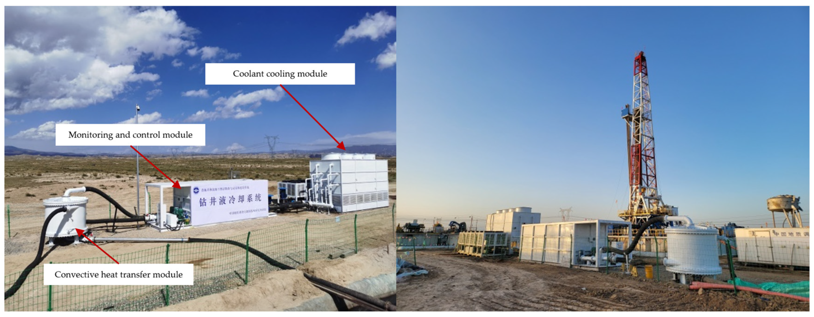
This article designs and develops a closed drilling fluid cooling system, which mainly includes a coolant cooling module, a convective heat exchange module, and a monitoring and control module. The coolant cooling module adopts a cascade cooling mode, with evaporative cooling as the main method and forced cooling to increase efficiency. The wide gap stainless steel spiral plate heat exchanger is preferred, and can achieve one-click constant-temperature automatic operation.
(2)
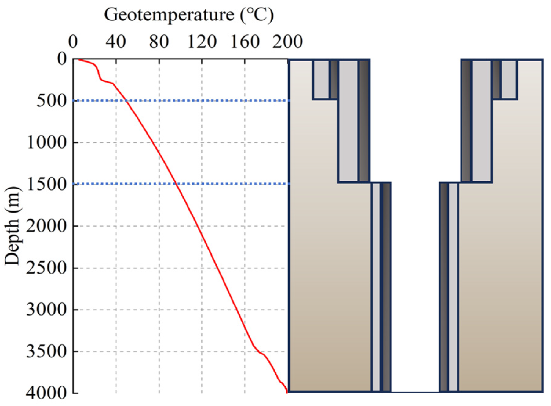
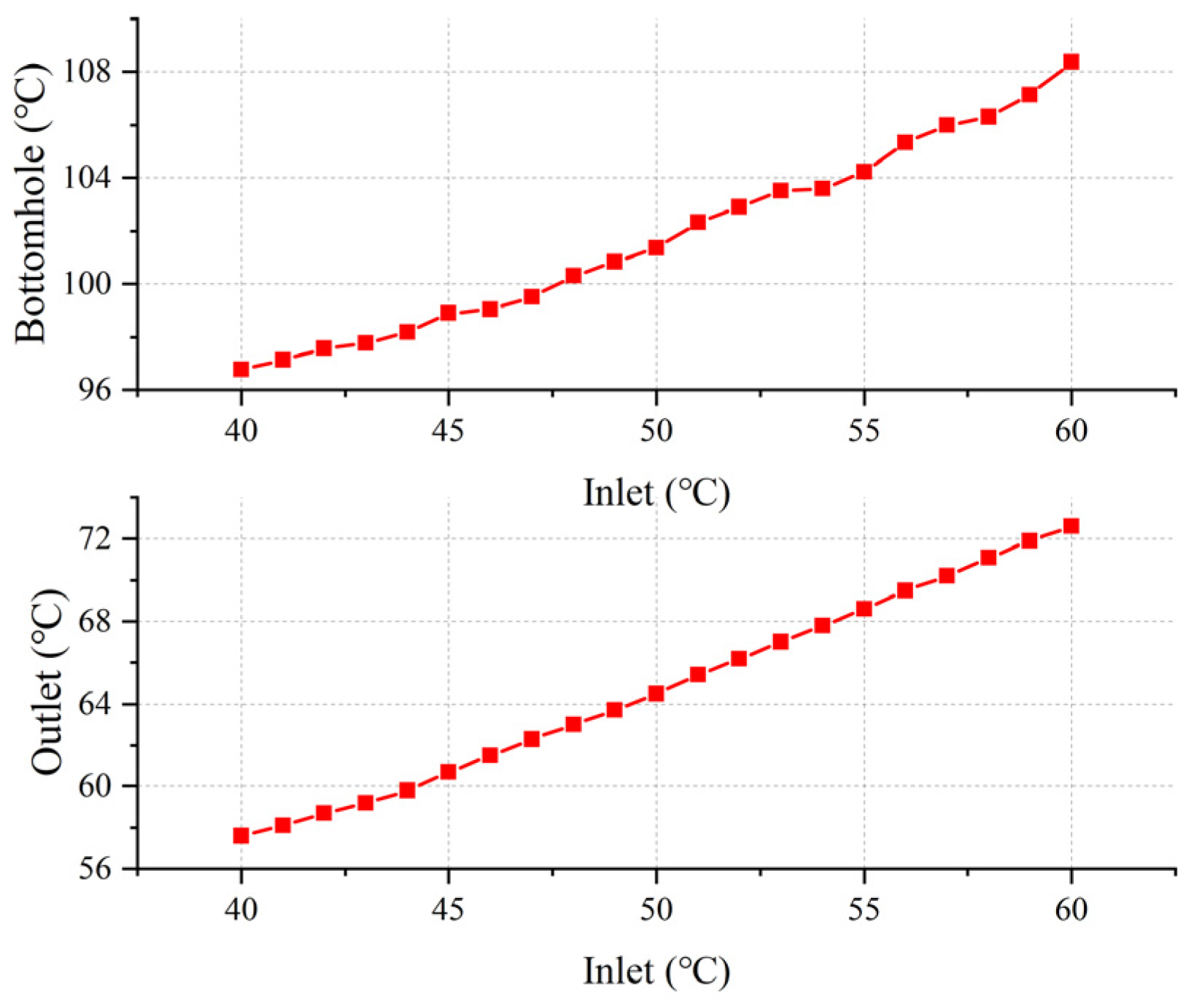
A transient temperature prediction model for the wellbore circulation is established based on the formation conditions and drilling design of the dry hot rock trial production well. Under the conditions of a drilling fluid displacement of 30 L/s and a bottomhole circulation temperature not exceeding 105 °C, the inlet and outlet temperatures of the drilling fluid are calculated to be 55.6 °C and 69.2 °C, respectively, and the circulating heat transfer is not less than 1785 kW. By selecting a reserve coefficient of 1.5 and a heat transfer efficiency of 80%, the heat transfer area of the spiral plate heat exchanger is calculated to be no less than 75 m2.
(3)
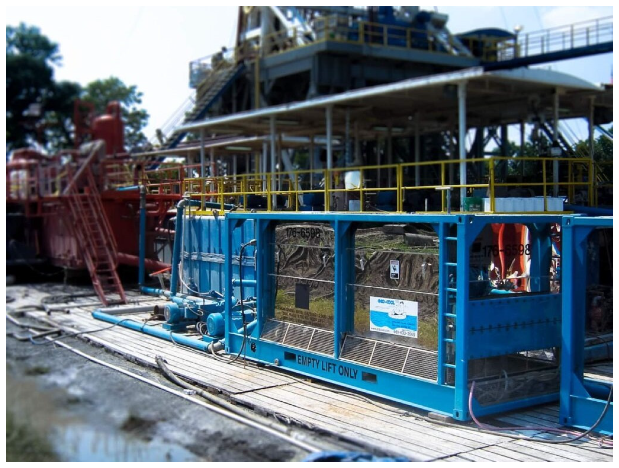
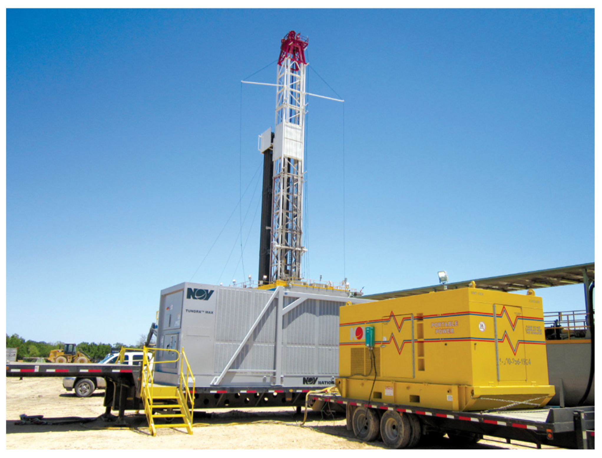
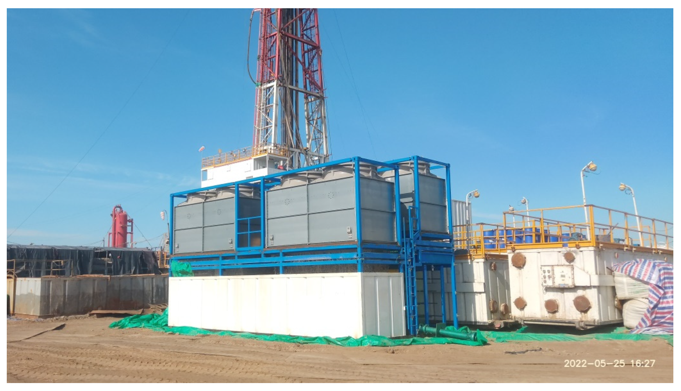
The drilling fluid cooling system designed in this article has been applied to the GH-02 dry hot rock trial production well and the shale oil well in Dagang Oilfield, and has achieved ideal application results. During the operation of the drilling fluid cooling equipment, the rheological properties of the drilling fluid are stable, and the evaporation rate is significantly reduced. At the same time, the failure rate of the drilling mud pumps significantly decreases, and the performance and service life of downhole tools such as the drill bits, screws, and MWD are stable. The imaging logging instruments are smoothly deployed, and the drilling system operates safely and efficiently.

Author Contributions

Conceptualization, H.Z. and K.L.; methodology, K.L.; software, Z.W.; validation, S.S. and Z.W.; formal analysis, K.L.; investigation, K.L.; resources, H.Z. and B.L.; data curation, H.Z.; writing—original draft preparation, K.L.; writing—review and editing, K.L.; visualization, Z.W.; supervision, S.S.; project administration, H.Z.; funding acquisition, H.Z. All authors have read and agreed to the published version of the manuscript.

Funding

National Science and Technology Major Project of the Ministry of Science and Technology of China (No. 2024ZD1000803); National Public Welfare Geological Survey Project (No. DD20240121).

Data Availability Statement

The authors confirm that the publicly available data is already included in the study.

Conflicts of Interest

The authors declare no conflict of interest.

References

  1. Duchane, D.; Brown, D. Hot dry rock (HDR) geothermal energy research and development at Fenton Hill, New Mexico. Geo-Heat Cent. Q. Bull. 2002, 23, 13–19. [Google Scholar]
  2. Chen, Z.; Wang, X.; Peng, B.; Zhang, H.; Li, Z.; Gong, H. Research Status and Progress on Technologies for Exploration of Dry Hot Rock Resources in China. J. Phys. Conf. Ser. 2024, 2913, 012002. [Google Scholar] [CrossRef]
  3. Zhang, J.; Liu, Y.; Lv, J. Investigation of heat extraction performance of supercritical CO2 in 2D self-affine rough intersecting fracture. Geoenergy Sci. Eng. 2024, 243, 213352. [Google Scholar]
  4. Zhang, J.; Liu, Y.; Lv, J.; Gao, W. The flow and heat transfer characteristics of supercritical mixed-phase CO2 and N2 in a 3D self-affine rough fracture. Energy 2024, 303, 131967. [Google Scholar]
  5. Wen, D.; Zhang, E.; Wang, G. Progress and Prospect of Hot Dry Rock Exploration and Development. Hydrogeol. Eng. Geol. 2023, 50, 1–13. [Google Scholar]
  6. Pan, D.; Wang, D.; Huang, J.; Zhang, W.; Zhao, Z.; He, Y. Case Analysis of DST Tools Low-Frequency Failures in HTHP Deep Well. Drill. Prod. Technol. 2023, 46, 165. [Google Scholar]
  7. Zhang, K.; Zhang, J.; Dai, W. Drilling technology for deep & ultra-deep well in West China. Drill. Prod. Technol. 2010, 33, 36–40. [Google Scholar]
  8. Hou, B.; Liu, W.; Han, L.; Liu, A. Research and application of 300 °C directional drilling system. China Pet. Mach. 2018, 46, 1–9. [Google Scholar]
  9. Guenot, A.; Maury, V. Practical advantages of mud cooling systems for drilling. SPE Drill. Complet. 1995, 10, 42–48. [Google Scholar]
  10. Li, W.; Huo, H.; Liu, H.; Zhang, L.; Jin, N.; Liu, X.; Liu, C.; Jia, S. Design and Application of a Mud Cooling Method for Offshore High Temperature Wells. In Proceedings of the ISOPE International Ocean and Polar Engineering Conference, Rhodes, Greece, 16–21 June 2024; ISOPE: Mountain View, CA, USA, 2024; p. ISOPE-I-24-073. [Google Scholar]
  11. Finger, J.; Jacobson, R.; Whitlow, G.; Champness, T. Insulated Drill Pipe for High-Temperature Drilling; Sandia National Laboratories: Albuquerque, NM, USA, 2000.
  12. Kohei, A.; Naganawa, S.; Bjarkason, E.K. Application of Insulated Drill Pipe to Supercritical/Super-Hot Geothermal Well Drilling. In Proceedings of the International Conference on Offshore Mechanics and Arctic Engineering, Melbourne, Australia, 11–16 June 2023; American Society of Mechanical Engineers: New York, NY, USA, 2023; p. V009T11A042. [Google Scholar]
  13. Liu, J.; Chen, E.; Li, G.; Yuan, L. Experimental study of drilling fluid cooling in deep wells based on phase change heat storage. Pet. Drill. Tech. 2021, 49, 53–58. [Google Scholar]
  14. Khan, A.; Bradshaw, C.R. Quantitative comparison of the performance of vapor compression cycles with compressor vapor or liquid injection. Int. J. Refrig. 2023, 154, 386–394. [Google Scholar]
  15. Li, K.; Zhang, Y.; Sun, Y.; Guo, W.; Li, B. Research and optimization of mud cooling system in gas hydrate drilling. Drill. Prod. Technol. 2013, 36, 34–36. [Google Scholar]
  16. Xi, Q.; Peng, J.; Dai, Q.; Zhou, Q.; Tang, C.; Yang, Q. Development of ZLQ030-75 High Temperature Drilling Fluid Cooling Device. Oil Field Equip. 2023, 52, 53–58. [Google Scholar]
  17. Liu, W.; Sun, Y.; Guo, W.; Li, B.; Li, Z. Comparative Analysis and Research on Light Pipe and Threaded Pipe Type Heat Exchanger of Mud Refrigeration. Prospect. Eng. Geotech. Drill. Eng. 2013, 40, 5. [Google Scholar]
  18. Li, K.; Zhang, Y.; Wang, H.; Liang, J.; Li, X.; Wu, J.; Li, X. Design of Cooling System for Gas Hydrate Drilling Mud in Frozen Soil Region and the Calculation of Important Factors. Prospect. Eng. Geotech. Drill. Eng. 2014, 41, 45–48. [Google Scholar]
  19. Liang, X.; Zhao, C.; Zhao, X.; Zhang, Y.; Bai, Y.; Yang, M. Development of the Drilling Fluid Surface Cooling System Based on Heat Pipes. China Pet. Mach. 2023, 51, 24–32. [Google Scholar]
  20. Yang, M.; Tang, D.; Chen, Y.; Li, G.; Zhang, X.; Meng, Y. Determining initial formation temperature considering radial temperature gradient and axial thermal conduction of the wellbore fluid. Appl. Therm. Eng. 2019, 147, 876–885. [Google Scholar]
  21. Wang, X.; Wang, Z.; Deng, X.; Sun, B.; Zhao, Y.; Fu, W. Coupled thermal model of wellbore and permafrost in Arctic regions. Appl. Therm. Eng. 2017, 123, 1291–1299. [Google Scholar]
Figure 1. FRESHWATER GEO-COOLER cooling equipment.
Energies 18 01736 g001
Figure 2. TUNDRA MAX Mud Chiller cooling equipment.
Energies 18 01736 g002
Figure 3. Application of Type-ZLQ030-75 high-temperature drilling fluid cooling system.
Energies 18 01736 g003
Figure 4. Drilling fluid cooling system for well GH-02.
Energies 18 01736 g004
Figure 5. Structure and principle of spiral plate heat exchanger.
Energies 18 01736 g005
Figure 6. Geotemperature distribution and structure of well GH-02.
Energies 18 01736 g006
Figure 7. Geometric model and grids.
Energies 18 01736 g007
Figure 8. Temperature distribution of drilling fluid in wellbore after stable circulation at different inlet temperatures.
Energies 18 01736 g008
Figure 9. Predicted values of bottomhole temperature and outlet temperature.
Energies 18 01736 g009
Figure 10. Application of drilling fluid cooling system developed in this article in GH-02 well.
Energies 18 01736 g010
Figure 11. Logging and model prediction values of inlet and outlet temperatures and bottomhole circulating temperature in 2817 m~4013 m section of GH-02 well.
Energies 18 01736 g011
Figure 12. Drilling fluid cooling system was used in shale oil wells, Dagang Oilfield.
Energies 18 01736 g012
Table 1. Structure of well GH-02.
Diameter of Drill Bit
(mm)
Specification of Casing
(mm)
Depth
(m)
Cement Slurry Return Height
(m)
First layer444.5339.7 × 10.920–500500
Second layer311.2244.5 × 10.030–15001500
Third layer215.9177 × 11.511500–40002500
Table 2. Parameters required for calculation process.
ParameterSymbolUnitValue
Inlet temperatureDrilling fluidT11°C69.2
RefrigerantT21°C28.0
Outlet temperatureDrilling fluidT12°C48.8
RefrigerantT22°C42.4
Circulating flow rateDrilling fluidQ1m3/h86.4
RefrigerantQ2m3/h160
DensityDrilling fluidρ1g/cm31.33
Refrigerantρ2g/cm31.00
Specific heatDrilling fluidc1J/(kg·°C)3290
Refrigerantc2J/(kg·°C)4200
Thermal conductivityDrilling fluidλ1W/(m·°C)0.62
Refrigerantλ2W/(m·°C)0.59
Dynamic viscosityDrilling fluidμ1mPa·s15
Refrigerantμ2mPa·s1.01
Kinematic viscosityDrilling fluidγ1m2/s11.28 × 10−6
Refrigerantγ1m2/s1.01 × 10−6
Thickness of heat exchanger platesδmm4
Thermal conductivity of heat exchanger platesλW/(m·°C)16.2
Disclaimer/Publisher’s Note: The statements, opinions and data contained in all publications are solely those of the individual author(s) and contributor(s) and not of MDPI and/or the editor(s). MDPI and/or the editor(s) disclaim responsibility for any injury to people or property resulting from any ideas, methods, instructions or products referred to in the content.

