Article

Wide-Area Damping Control for Clustered Microgrids

by
Rossano Musca
1,*,
Eleonora Riva Sanseverino
1,
Josep M. Guerrero
2,3 and
Juan C. Vasquez
3
1
Engineering Department, University of Palermo, 90128 Palermo, Italy
2
Department of Electrical Engineering, Valladolid University, 47011 Valladolid, Spain
3
Center for Research on Microgrids (CROM), AAU Energy, Aalborg University, 9220 Aalborg, Denmark
*
Author to whom correspondence should be addressed.
Energies 2025, 18(7), 1632; https://doi.org/10.3390/en18071632
Submission received: 3 February 2025 / Revised: 15 March 2025 / Accepted: 21 March 2025 / Published: 25 March 2025

Abstract

:
The increasing integration of renewable energy sources and distributed generation has led to new challenges in maintaining power system stability. This work presents a novel approach to wide-area damping control (WADC) for clustered microgrids, addressing inter-area oscillations and enhancing system stability. The proposed methodology leverages wide-area measurements and clustering algorithms to coordinate microgrid participation in damping control. A specific WADC concept is first formulated, detailing the mathematical background and the emergence of damping couplings. A bio-inspired flocking algorithm is introduced to determine how the microgrids are clustered, coordinated, and controlled. For that, three particular principles of the flocking algorithm are discussed. The developed control strategy is applied to the IEEE 68-bus benchmark system, where microgrids serve as actuators of the WADC to stabilize the oscillations in the system. Simulation results demonstrate significant improvements in damping performance, achieving stable system dynamics with minimal impact on microgrid resources. The findings highlight the feasibility of integrating microgrids into wide-area control schemes, offering a scalable solution for modern power grids with high renewable penetration.

1. Introduction

The global demand for reliable, sustainable, and efficient energy systems has given rise to innovative solutions in power generation, distribution, and consumption. Among these, smart grids and microgrids stand out as transformative technologies, reshaping the way energy is managed and utilized. Smart grids represent an evolution of traditional electrical grids, integrating advanced digital technology to enhance the monitoring, control, and optimization of energy flows. These systems leverage data from interconnected sensors, smart meters, and automation tools to enable real-time decision-making, improve efficiency, and accommodate renewable energy sources such as solar and wind. By fostering two-way communication between utilities and consumers, smart grids empower users to make informed energy choices while reducing overall environmental impact. On the other hand, microgrids are localized energy systems that can operate independently or in conjunction with the main grid. These smaller-scale networks incorporate distributed energy resources, including renewable power generation, energy storage, and advanced control systems. Together, smart grids and microgrids represent a paradigm shift in energy infrastructure, offering solutions to modern challenges such as grid stability, energy security, and climate change mitigation. For gaining technical and economic advantages, microgrids can be generally clustered together, through the connection and the control of multiple microgrids within a certain range of distance. Clusters of microgrids can be determined by applying different kinds of algorithms, and they can also be conveniently regarded as smart grids under some conditions [1]. In the field of microgrid control, ref. [2] provides a comprehensive survey of planning and control methodologies for microgrids and networked microgrids. A review of control strategies for microgrid networks is discussed in [3]. The work in [4] discusses smart hierarchical controllers for frequency control in low-inertia systems. Different methodologies to identify low-frequency inter-area oscillations using smart grid models are described in [5,6]. Further aspects of load frequency control and stability analysis in microgrids are discussed in [7,8]. These works refer to microgrid control strategies based on local area control signals. Wide-area damping controls (WADC) and wide-area monitoring, protection, and control (WAMPAC) schemes are advanced control systems designed to enhance the stability and reliability of large-scale power grids. In modern power systems, increased penetration of renewable energy, interconnections between distant regions, and fluctuating loads can lead to low-frequency oscillations that jeopardize grid stability. WADCs address this challenge by leveraging wide-area measurement systems (WAMS) and phasor measurement units (PMUs) to collect real-time data across vast geographical areas. By analyzing these data, WADCs detect and mitigate oscillations, coordinating control actions such as adjustments to power system stabilizers (PSSs) of synchronous machines, flexible AC transmission systems (FACTS), and other grid elements. By providing a comprehensive view of system dynamics, WADCs enable coordinated decision-making and control actions to enhance grid performance. These controls play a critical role in maintaining system stability, enhancing resilience, and enabling the integration of diverse energy resources into the grid. In the field of WADC and inter-area oscillations, ref. [9] proposes a two-level wide-area control to tolerate communication failures, while in [10], a delay-dependent wide-area dynamic output feedback controller is introduced for the mitigation of inter-area oscillations. In these works, conventional actuators are always considered for the application of the WADC scheme.
Only a few works have addressed the combination of wide-area controls and microgrids. The work [11] presents a smart grid testbed for wide-area monitoring and control systems, aimed at testing and analyzing the performance and the security of wide-area applications. In [12], an adaptive wide-area control is proposed, considering time delays and conventional PSSs as actuators. The work [13] investigates the application of wide-area measurement and control for voltage assessment in hybrid AC/DC smart grids. A PMU-based distributed wide-area monitoring scheme for implementation in smart grids is presented in [14]. These related works focus on measurements, on monitoring, or on voltage aspects, while the possibility of frequency control through WADC with clustered microgrids as actuators is not addressed. In particular, no works specifically investigate the potential use of microgrids as actuators of a wide-area control for increasing the damping of the system, with the precise aim of containing the inter-area oscillations and thus enhancing the oscillatory stability.
This work addresses the identified research gap, with a twofold contribution: first, the development of a specific WADC for application to microgrids serving as actuators is proposed; then, a clustering method for the participation of microgrids in the illustrated WADC architecture is presented. The combined concepts of WADC and clustered microgrids are finally applied to a detailed case study, based on the IEEE 68-bus standard system. The results show that the proposed concept can provide a remarkable improvement in the dynamic characteristics of the system, allowing for increased integrations of renewable energy sources while also enhancing damping and oscillatory stability of the system. The remaining part of the article is organized as follows. The proposed WADC for damping inter-area oscillations is illustrated in Section 2, along with a comprehensive mathematical background. The proposed method of microgrid clustering for participation in WADC is described in Section 3, comparing with other existing methods. The case study is presented in Section 4, applying the proposed control concepts to the standard IEEE 68-bus system. Finally, Section 5 draws the conclusions of the work with final remarks.

2. Wide-Area Damping Control

The concept of centralized wide-area damping control is briefly revisited here, presenting the fundamental theory and characteristics of the control. The principle of the proposed control is essentially related to the transient power change Δ p i * given by
Δ p i * = K w i ω a v e ω i = K w i 1 N k = 1 N ω k ω i
where K w i is a proportional gain, ω i is the local frequency, and ω a v e is the system’s average frequency. In the standard formulation, ω a v e is computed according to the frequency measurements ω k obtained from a network of PMUs distributed across the systems. The measurements are sent to a phasor data concentrator (PDC), which computes the average values of all the received frequency measurements, acting as a central computation unit. The computed average frequency ω a v e is then transmitted to the local actuators of the system. According to the illustrated concept, the input signals of the WADC scheme are the measured frequencies in the system, while the output signal is the average value ω a v e of all the input frequencies. Since the underlying idea of the presented wide-area control is a transient change in the active power output, the actuation can be realized relying on different technologies, like the ones which can be typically found within a microgrid (Figure 1).
The main actuators discussed in [15] are sources interfaced through grid-following and grid-forming power converters. In the case of grid-following control, assuming the standard current vector control, the participation in the presented WADC would require the following modifications:
Δ p * = K w ω a v e ω P L L
p e r r = p * + Δ p * p m e a s
i P c m d = K P p e r r + K I p e r r d t
where ω P L L is the frequency acquired within the phase-locked loop (PLL); p * and p m e a s are active power set-point and measurement, respectively; K P and K I are proportional and integral gains; and i P c m d is the reference current component for active power control. In the case of grid-forming control, assuming the well known swing-based control, the participation in the presented WADC would require the following modifications:
Δ p * = K w ω a v e ω c m d
p e r r = p * + Δ p * p m e a s ω c m d ω r e f / R
ω c m d = ω r e f + 1 2 H p e r r d t
where ω c m d is the frequency determined within the synchronization loop; p * and p m e a s are active power set-point and measurement, respectively; H and R are gains corresponding to inertia constant and frequency droop of synchronous power plants; and ω r e f is the reference frequency equal to 1 per unit. Even if some elements and controls can be more suited for the actuation, the presented WADC is technology-agnostic and can be implemented with any element capable of adjusting their active power output over a very short transient. The preferable asset would be a battery energy storage system (BESS) controlled in grid-forming mode, since this asset can guarantee availability and performance. However, considering a cluster of heterogenous resources, the transient change in active power can be achieved with different elements and sophisticated coordination. This consideration introduces the opportunity of involving clusters of microgrids in the actuation of the wide-area control of the system. This will ultimately result in a change in the active power injections, which is expected to lead to a significant improvement in the dynamic characteristics of the power system. This aspect can be better illustrated with reference to the aggregated dynamics of power system areas. In this simplified representation, the higher-order dynamics of machines and controllers are neglected, loads are assumed to be elements with no dynamics, and transmission lines and cables are considered without losses. Despite the simplifying assumptions, the wide-area characteristics of the system can be effectively represented with the aggregated dynamics [15]. Following this approach, a given area i can be described by the following equation:
M i ω ˙ i = p i * p i D i ω i
where p i * is the active power reference, p i is the active power exchange, M i is the aggregated inertia, and D i is the aggregated damping coefficients of the area. Considering that p i can be expressed in terms of angles θ , and that the angle can be expressed in terms of frequency through θ ˙ = ω n ω , (9) can be arranged as follows:
M i θ ¨ i + D i θ ˙ i + ω n j = 1 N K i j ( θ i θ j ) = ω n p i *
where K i j are the synchronizing coefficients, given by [16]:
K i j = Y i j V i V j cos ( θ i 0 θ j 0 )
where V i and V i are the voltage magnitudes at the equivalent nodes of area i and area j, respectively; Y i j is the admittance (purely imaginary under the given assumptions) between area i and area j; and θ i 0 and θ j 0 are the initial steady-state values of the angles. In (9), the integer N denotes the number of areas in the system. The dynamics of the N areas of the system can be therefore described with a system of Equation (9). The equations are expressed in per-unit values of the apparent power size S r of the corresponding area, determined as sum of all the rated generation powers. Therefore, when building the system of equations, it is essential to include appropriate base changes to harmonize all equations on a common power base S b .
With the application of the presented WADC, (9) modifies with the inclusion of the injected power Δ p i * determined according to (1), leading to
M i θ ¨ i + D i θ ˙ i + ω n j = 1 N K i j ( θ i θ j ) ω n k = 1 W Δ p k = ω n p i *
where W denotes the group of actuators belonging to the area i. Since the area derives from the condition of coherency, the following approximation can be assumed for all actuators of the area:
ω a c t ω i
where ω a c t is the frequency acquired at the terminal of the actuator, corresponding f.i. to ω P L L in the case of grid-following converters and to ω c m d in the case of grid-forming converters. The single contributions of the actuators can be therefore added together with a total gain K w i , resulting in
M i θ ¨ i + D i θ ˙ i + ω n j = 1 N K i j ( θ i θ j ) + ω n K w i ( ω i ω a v e ) = ω n p i *
which can be also written as follows:
M i θ ¨ i + D i θ ˙ i + K w i N j = 1 N ( θ ˙ i θ ˙ j ) + ω n j = 1 N K i j ( θ i θ j ) = ω n p i *
Comparing (9) and (14), it can be easily observed that the application of the WADC modifies the coefficients of the damping matrix D . While in the power system without wide-area control the matrix D is diagonal, with the application of the WADC the matrix will also have off-diagonal elements, tending to dense patterns when several areas of the system are involved (Figure 2).
The additional terms in (14) can be regarded as damping couplings [15,17], and they are ultimately introduced by the transient changes in the active power injection, as established in the presented control.

3. Microgrid Clustering, Collaboration, and Control

The application of the presented wide-area control to microgrids distributed across the power system is applied with a comprehensive approach. The application considers not only how the microgrids are controlled, but also how they are clustered and how they are coordinated. This comprehensive approach is realized by relying on the principles of flocking algorithm.
The flocking algorithm is a bio-inspired computational method that simulates the collective behavior of decentralized systems. The denomination derives from the fact that the algorithm is particularly inspired by the natural movement of flocks of birds. Similar collective behaviors are also observed in schools of fish, or herds of animals. The method was first introduced by the seminal work in [18], demonstrating how simple local rules could relate to complex group behaviors. The rules of flocking algorithms can be summarized with the following three fundamental principles:
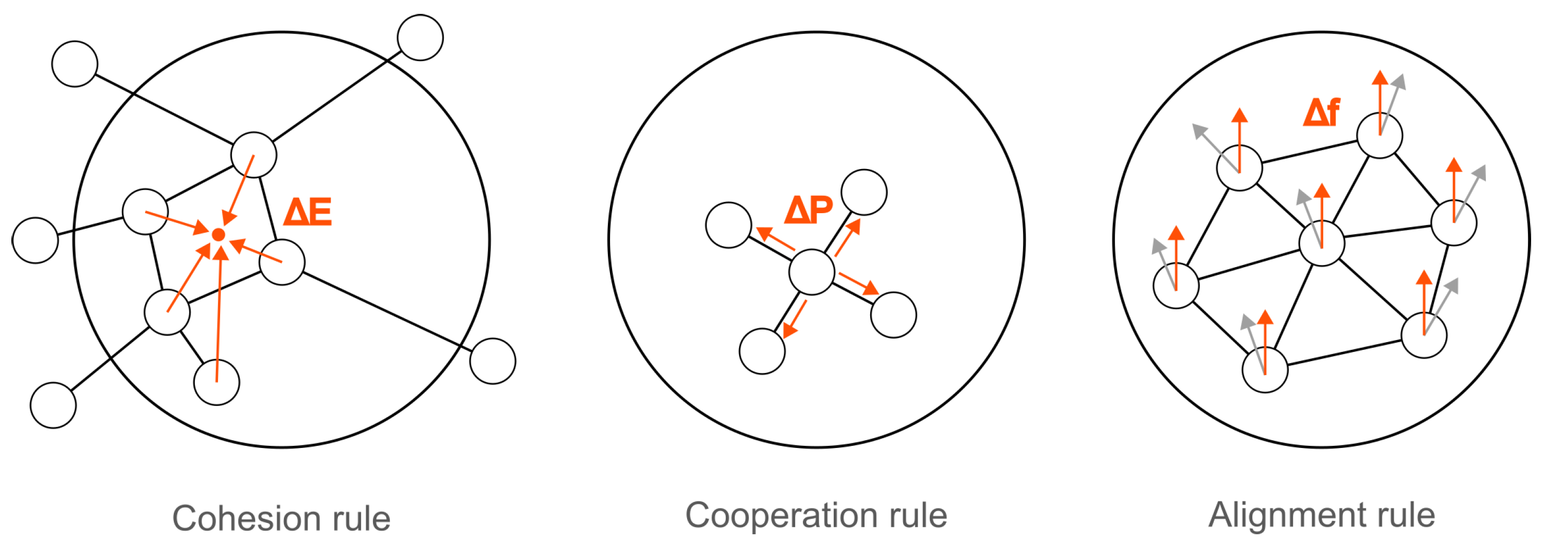
  • Cohesion: Agents are guided to move towards the average position of their neighbors. The aim of this principle is to form and maintain group unity.
  • Separation: Agents are guided to maintain a minimum distance from their neighbors. The aim of this principle it to avoid collisions or overlaps.
  • Alignment: Agents are guided to steer towards the average direction or velocity of their neighbors. The aim of this principle is to achieve a coordinated movement.
These principles allow individual agents to interact with their local environment while collectively exhibiting global behaviours, such as synchronized motion or dynamic formations.
The algorithm is typically applied to dynamic systems of n agents, where the position and velocity of the agents are described by a second-order motion dynamics [19,20]. In the analogy with the microgrids and the electric system, the position of the birds in the flock corresponds to the phase θ of the wide-area actuators, and the velocity of the birds corresponds to the frequency ω of the wide-area actuators. In fact, the same mathematical relation subsists between those quantities. It is easy to demonstrate that a formal analogy exists between multi-agents system described by second-order motion equations and the formulation given in (9) for electric power systems. The flocking algorithm has been selected among other possible clustering techniques because of its specific characteristics, which conveniently match the main requirements of the proposed application of wide-area damping control to microgrids. As discussed next, the three principles of the algorithm allow to address three fundamental aspects of the proposed control strategy.
The application of the flocking method to the case of microgrids and wide-area control is structured in three stages, according to the three general principles introduced before. The first stage is cohesion: this corresponds to the formation of microgrid clusters according to their relative position in the network, accounting both for electrical distances and center of inertia formed by synchronous machines. This ultimately results in guaranteeing a proper coherency in the electric system. The second stage is cooperation: this corresponds to the handling of the task assigned to the cluster, dividing the requested transient power injection according to the individual capabilities and characteristics. This ultimately results in guaranteeing proper coordination between microgrids. The third stage is alignment: this corresponds to the application of the presented wide-area control, relying on the differences computed with respect to the average frequency of the system. This ultimately results in guaranteeing the maximum possible alignment of the frequency in different parts of the system. The three parts of the proposed application to microgrids are illustrated in Figure 3, and they are described in detail in the following subsections.

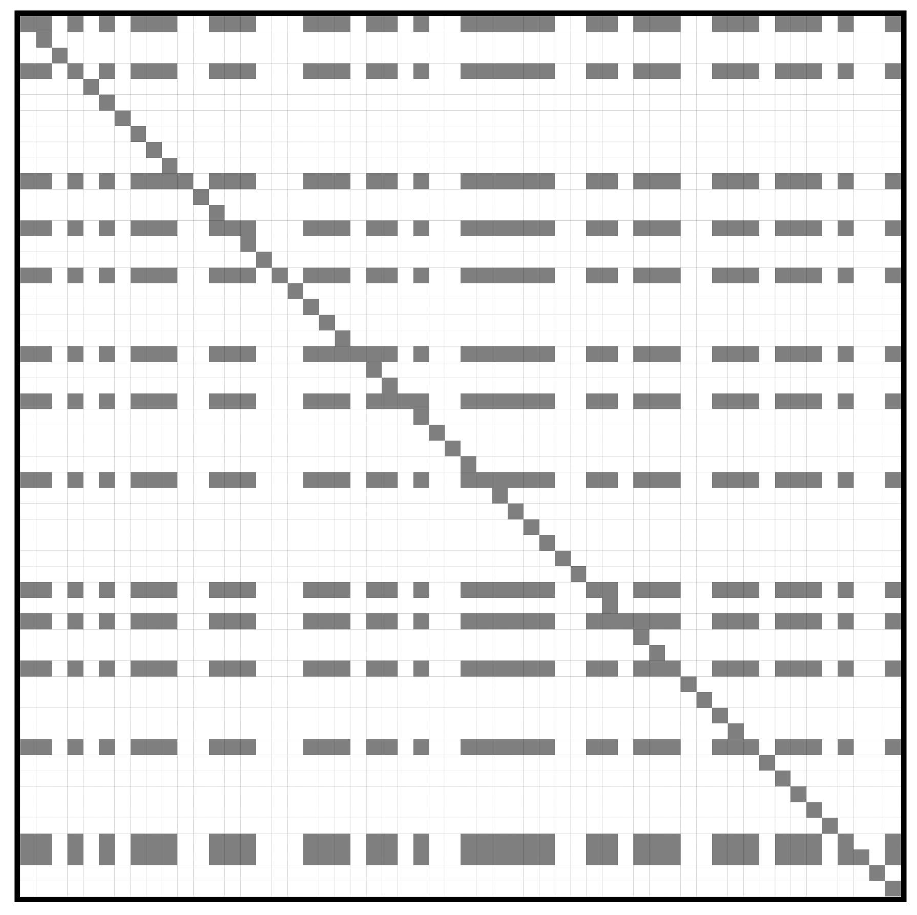
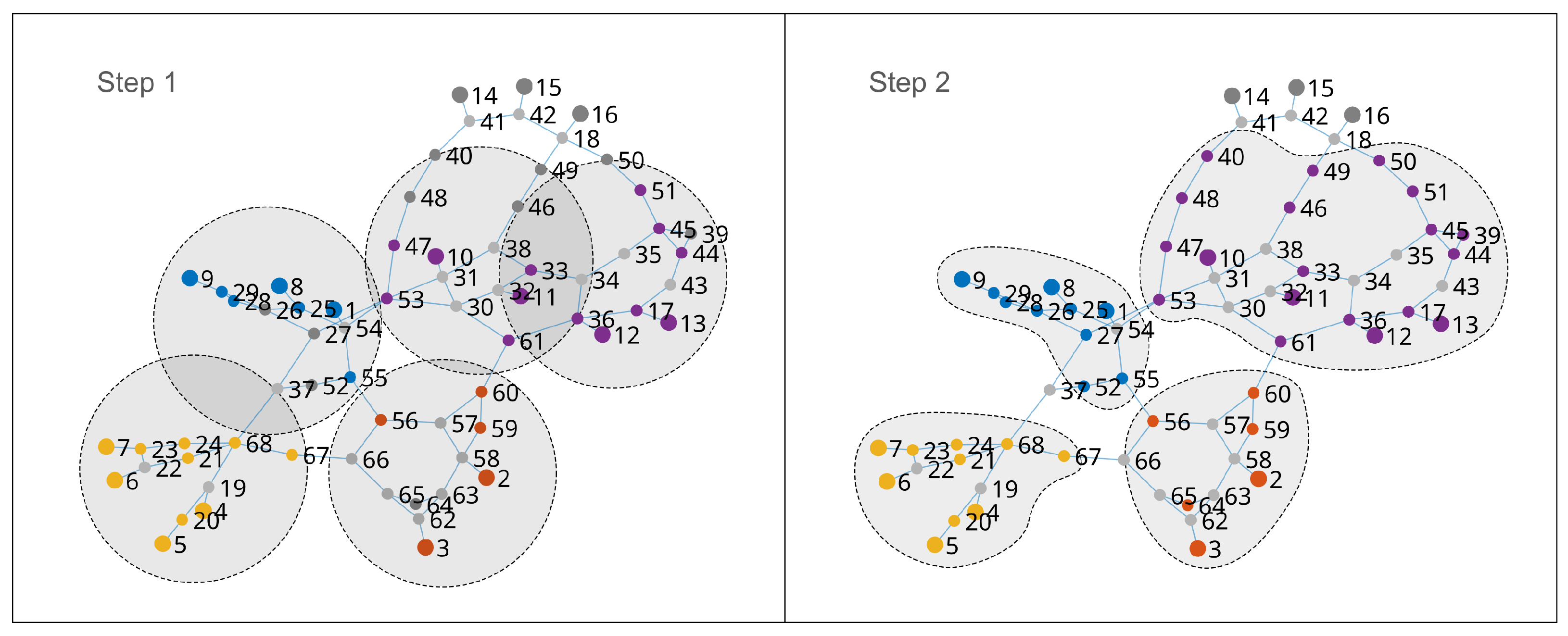
3.1. Cohesion: Microgrid Clustering

The principle of cohesion is applied here with the aim of identifying clusters of microgrids for participation in the wide-area control of the system. The formation of the clusters is made according to the following procedure. The electrical network is first converted to a graph representation. The network nodes are taken as vertices, while the lines and the transformers are taken as edges of the graph. The edges are weighted according to the impedance module of the branch. The nodes with generation and the those with one or more microgrids downstream are marked. For each node with generation, if a cluster is not yet assigned, a new cluster is created and assigned to the node. Then, a shortest path search based on Dijkstra’s algorithm is performed. In this way, all the nearest neighbor nodes within a given radius are found. The radius is determined proportionally to the strength of node, which is given in terms of energy E = H S , where S is the rated power and H is the inertia constant of the connected machines. During this first part of the algorithm, the nearest nodes with microgrids found within the searching radius are also assigned to the same cluster of the source node. Then, for each node with one or more microgrids downstream, a shortest path search based on Dijkstra’s algorithm is performed. In this case, the radius for finding nearest neighbor nodes starts with a given value r i t e r . The neighbor nodes found in the search are assigned to the same cluster of the source node. This second part of the algorithm is repeated with increasing values of the searching radius, until all the nodes with microgrids are assigned to a cluster. The described procedure is summarized in Algorithm 1.
This procedure ultimately leads to the organization of the microgrids into clusters for participation in wide-area control. The clustering is performed by taking into account the position of the microgrids through the electrical distances, which refer to the rated powers and inertia constants of synchronous machines as centers of attraction for the formation of the clusters. The application of this principle therefore ensures proper cohesion both between the microgrids of the same cluster and between the cluster and the other neighboring elements in the system.
It is worth noting that identification of the clusters can also be achieved according to time-varying procedures. A dynamic clustering of the microgrids would account for possible topology changes in the power system, leading to more accurate and consistent grouping results. This aspect could represent a topic for further investigation and development of the work.
Algorithm 1 Microgrid clustering for cohesion
Require:  G ( V , E ) , weighted graph                                                 ▹ Representation of the system
Require:  A V , set of nodes with generation
Require:  B V , set of nodes with microgrids
Ensure:  C l u s t e r s , dictionary of nodes to cluster
    1:
C l u s t e r s empty dictionary
    2:
C l u s t e r 0
    3:
for each i in A  do
    4:
      if  C l u s t e r s ( i ) > 0  then
    5:
            continue
    6:
       C l u s t e r C l u s t e r + 1
    7:
       C l u s t e r s ( i ) C l u s t e r
    8:
       S i rated power of i
    9:
       H i inertia constant of i
  10:
       r i radius proportional to H i S i
  11:
      Shortest path search with radius r i
  12:
       C nearest neighbours within r i
  13:
      for each j in C  do
  14:
            if  j A  then
  15:
                  C l u s t e r s ( j ) C l u s t e r                                       ▹ Group together nearby generation
  16:
            if  j B  then
  17:
                  C l u s t e r s ( j ) C l u s t e r                                       ▹ Group together nearby microgrids
  18:
i t e r 0
  19:
while  B contains unclustered nodes do
  20:
       r i t e r radius proportional to i t e r
  21:
      for each i in B  do
  22:
            Shortest path search with radius r i t e r
  23:
             C nearest neighbours within r i t e r
  24:
            for each j in C  do
  25:
                 if  j B  then
  26:
                        C l u s t e r s ( j ) C l u s t e r ( i )                       ▹ Group together discovered microgrids
  27:
       i t e r i t e r + 1
  28:
return  C l u s t e r s

3.2. Cooperation: Microgrid Collaboration

The principle of separation is applied here with the aim of distributing the total amount of transient power potentially required by the wide-area control among the microgrids of a same cluster. In this work, therefore, the separation is positively interpreted as a principle of cooperation. For a given cluster I , the required transient amount of active power Δ p * is divided among the microgrids according to their capabilities and characteristics. According to the principle of cooperation, the individual contribution Δ p k * of a given microgrid k of the cluster can be determined as follows:
Δ p k * = K k Δ p * k I
where K k represents the repartition coefficients. The determination of the coefficients K k can be made according to the relative size of each microgrid in the cluster and adapted according to the availability of resources within each microgrid for a given time schedule. For a given microgrid k, indicating the installed capacity with S k and resource availability with α k , the coefficient K k can be expressed as follows:
K k = α k S k S I k I
where S I is the sum of the installed capacity of all the microcrids in the cluster I . The parameter α k expresses the availability of the resources belonging to the microgrid for participation in the control. The availability varies with the considered time window and is a value between 0 and 1. The sum of all the coefficients K k of the cluster is therefore in the range 0 to 1. The determination of the coefficients K k can be also optimized according to additional economic and market considerations. This aspect is beyond the scope of this work and could represent a future research direction.

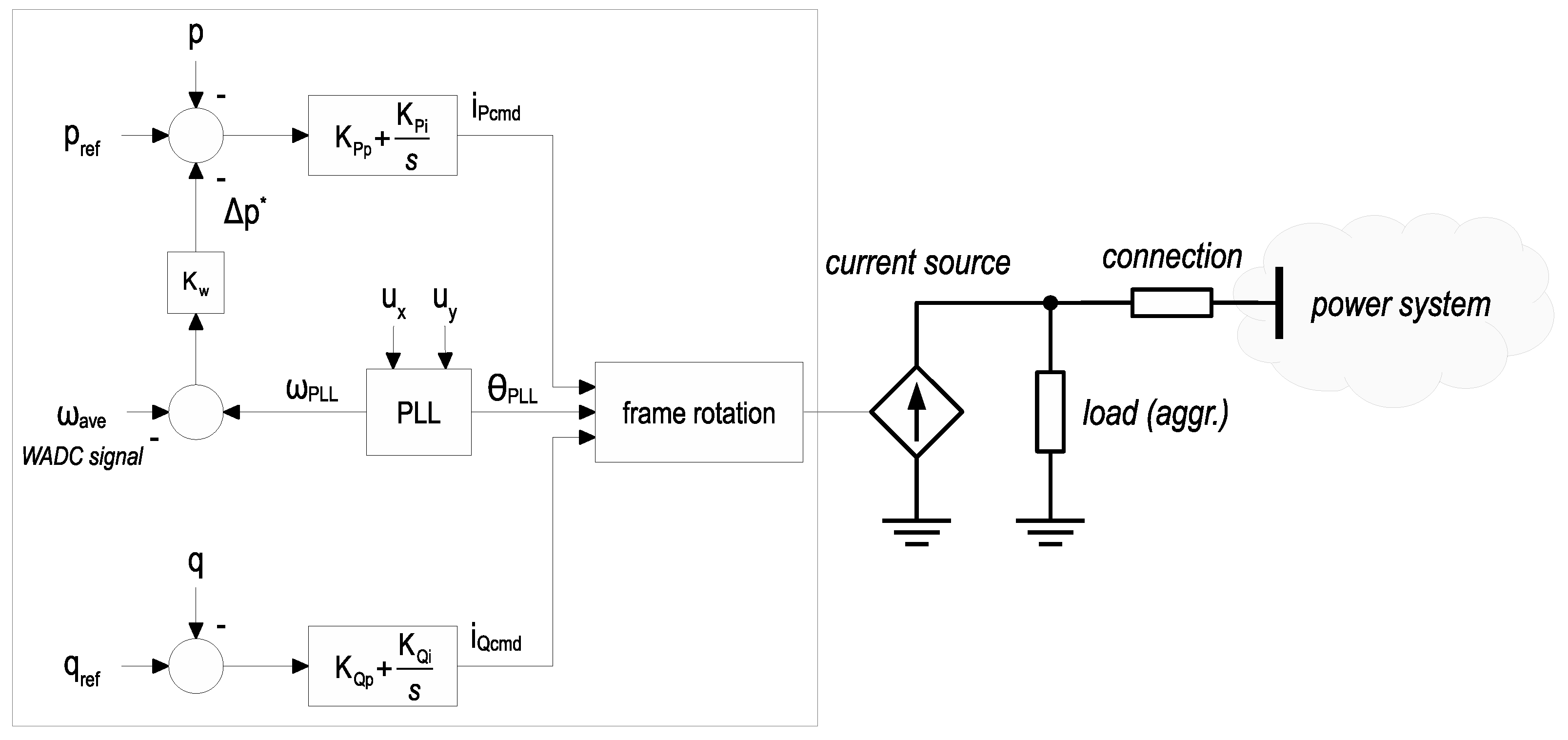
3.3. Alignment: Microgrids Control

The principle of alignment is achieved through the application of the wide-area control presented before. To demonstrate the alignment effect, it is possible to refer to two generic microgrids i and j of the same cluster. By applying (14) for the two microgrids, it is possible to write
M i ω ˙ i + D i ω i + K w ( ω i ω a v e ) + p i = p i *
M j ω ˙ j + D j ω + K w ( ω j ω a v e ) + p j = p j *
where the same gain K w has been assumed for sake of demonstration. Making the difference between (17) and (18), it leads to
M i ω ˙ i M j ω ˙ j + D i ω i D j ω j + K w ( ω i ω j ) + p i p j = p i * p j *
which can be also expressed in a more compact way as
M Δ ω ˙ = Δ p * Δ p D Δ ω K w Δ ω
under the assumption of comparable dynamics M and D in the two microgrids. Focusing on the last term in (20), which represents the contribution of the presented wide-area control, it can immediately be observed that the application of the control is opposite to the difference between the frequency of the two microgrids, pushing to have the same direction of frequency changes in both microgrids. Extending this consideration to all couples of microgrids in the cluster, it is possible to recognize that this control will ultimately bring the microgrids to be aligned with each other in terms of frequency deviations.
The control action can be performed by relying on the different resources and technologies available in the microgrid. The main actuators of the control are inverter-based resources, which are controlled in either grid-following or grid-forming mode. These resources can ensure a fast change in the active power, providing an effective transient support to the grid. The control action can be also performed by relying on the controllable loads of the microgrid. In this case, selected loads will modify their absorption during transient conditions, helping to reach the required change in the active power, as envisioned in the wide-area control architecture. A detailed discussion of strategies for executing control actions within single microgrids is a particular aspect that requires dedicated investigation and could represent a future research direction.

4. Case Study: IEEE 68-Bus System

4.1. Model Description

The IEEE 68-bus system was selected as a case study for the assessment of the proposed methodology. This system was selected as it is a well-known benchmark system that is widely used to analyze and test solutions concerning oscillatory stability, inter-area phenomena, and wide-area controls. The data of the system can be found in several works [21], making this benchmark system suitable for reproducibility and replicability. This system is a simplified model of the interconnected power grid that constitutes the electrical interconnection between the New England and New York areas. It consists of 68 buses and 16 synchronous machines, including 35 load buses with various static and dynamic load models. The elements of the system are distributed across five geographical areas. Two areas are represented in detail: the New England Transmission System (NETS) and the New York Power System (NYPS). The remaining three areas are represented with equivalent synchronous machines, which account for the power exchange between the neighboring areas.
The original IEEE 68-bus system was modified for the purposes of this study. In two detailed areas of the system, several microgrids were integrated, with a microgrid assigned to each node having a load consumption. This integration is based on the realistic consideration of having one or more microgrids downstream from the nodes that distribute power from the transmission level to the load centers. The installed capacity of the integrated microgrids is assumed to range from 10 to 30 MVA. In total, 35 microgrids were added to the network. The outline of the considered IEEE 68-bus system is shown in Figure 4. The circles represent microgrids, which have been modeled as groups of controlled resources. These resources are assumed to implement grid-following control, as this is the current standard for inverter-based resources. Based on the installed capacity and the availability of internal resources, each microgrid has the capability to provide a transient modification in active power when requested, thus participating in the wide-area control architecture. For this purpose, each microgrid has its own control center, which receives the reference average frequency ω a v e from the bulk system and, in turn, sends the local frequency measurements through the communication system. For the sake of preserving the original steady-state operating point of the benchmark system, the microgrids are assumed to initially provide no active or reactive power.
The model used to represent the microgrid is shown in Figure 5. The adopted control scheme is a conventional grid-following control. The outer loops control the active and reactive power, respectively. The active power control loop includes the application of the presented WADC, processing the difference between the remote signal ω a v e and the local frequency estimation ω P L L . The control includes the synchronization through a PLL. The implemented PLL is a conventional second-order synchronous reference frame (SRF) PLL, with the loop filter made by a PI controller and the virtual controlled oscillator made by a simple integrator. The block diagram is shown in Figure 6. According to the diagram, the local frequency ω P L L is determined within the PLL control per unit by dividing the output of the loop filter by the rated angular frequency ω n .
The application of the clustering algorithm for application of the cohesion principle gives the results shown in Figure 7. The different colors denote the clusters assigned by the cohesion principle. Given the size of the network, several nodes with one or more microgrids downstream are already clustered in the first step. The second step proceeds iteratively until all the nodes with microgrids have been clustered. The nodes corresponding to the three areas represented as equivalents are excluded from the procedure. The identified clusters for microgrid cohesion are summarized in Table 1. It can be noticed that all the microgrids of Area 2 (NYPS) have been grouped into one cluster, while the microgrids of Area 1 (NETS) have been divided between three clusters. This is related to the different topology and density of generation in the two areas.
For the application of the proposed wide-area control to clustered microgrids, the gain K w is set to 100 pu. For application of the cooperation rule, the parameters K k are assigned according to the installed capacities of the microgrids, while the parameters α k are assigned at the intervals 0.3 and 0.7, considering possible differences in the availability of the microgrids resources. The other parameters of the controlled sources that represent the microgrids are as follows: proportional and integral gain of the outer power control loops K p P = 1 pu, K i P = 10 pu; proportional and integral gain of the inner current control loops K p I = 1 pu, K i I = 100 pu; gains and time constant of the PLL control loop K p P L L = 60 pu, K i P L L = 900 pu, T f = 0.01 s.
The communication system is represented with delay blocks in the mathematical model of the power system. The delays are modeled with Padé rational approximation, using a strict second-order transfer function as described in [15,17]. With this approach, when the input varies from the steady-state value, the sudden initial change in the output is avoided. This initial change is typically exhibited by rational transfer functions with a numerator and denominator of the same order. The total round-trip delay is assumed to be randomly within the range of 300–400 ms.
For a comprehensive evaluation of the proposed method, the case study also includes the application of a conventional WADC scheme. In the conventional case, the actuation of the wide-area control is demanded to the synchronous machines of the power plants. Contrarily to the case of the proposed WADC with distributed microgrids, in the conventional case, the actuators are concentrated in a few locations within the system.

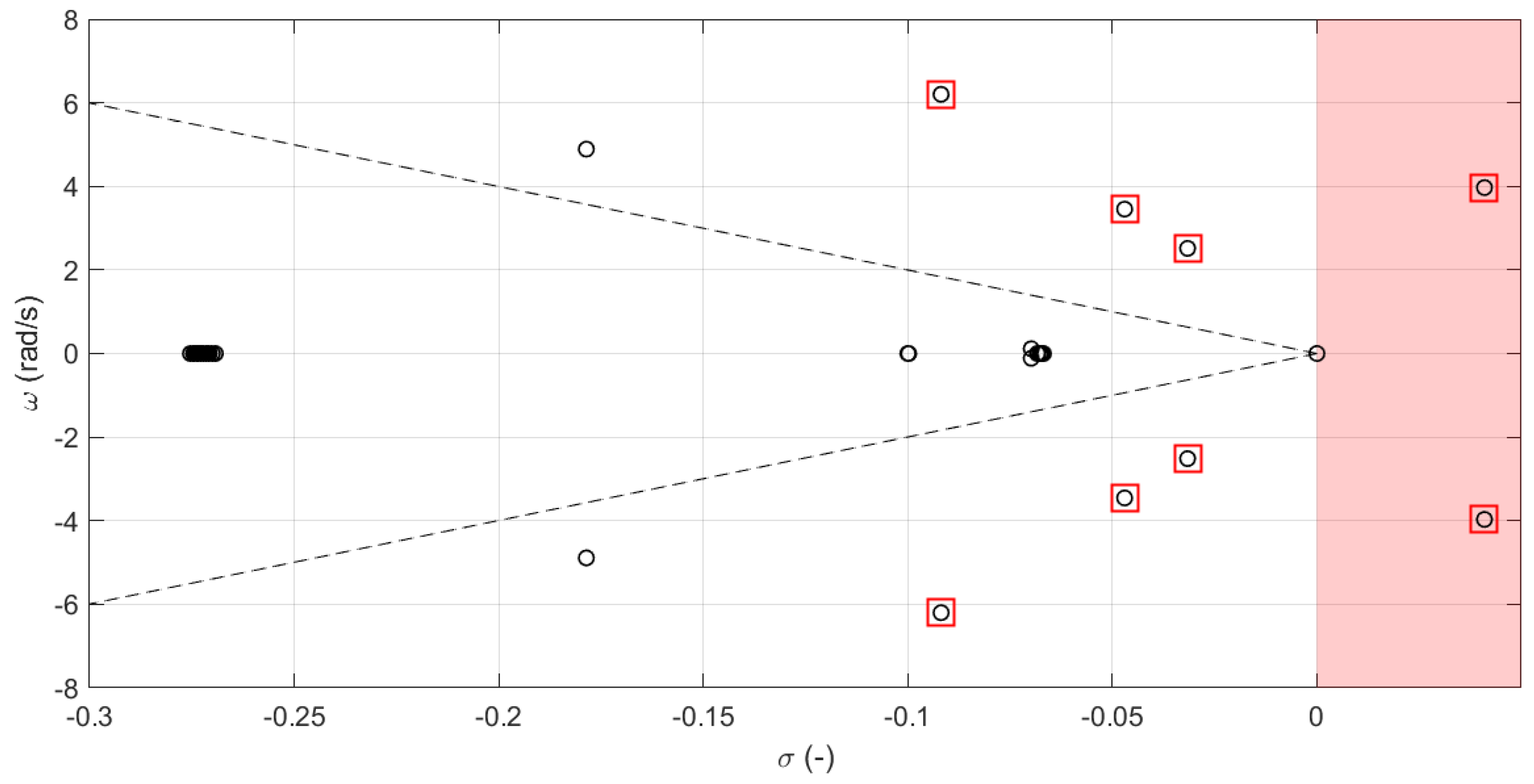
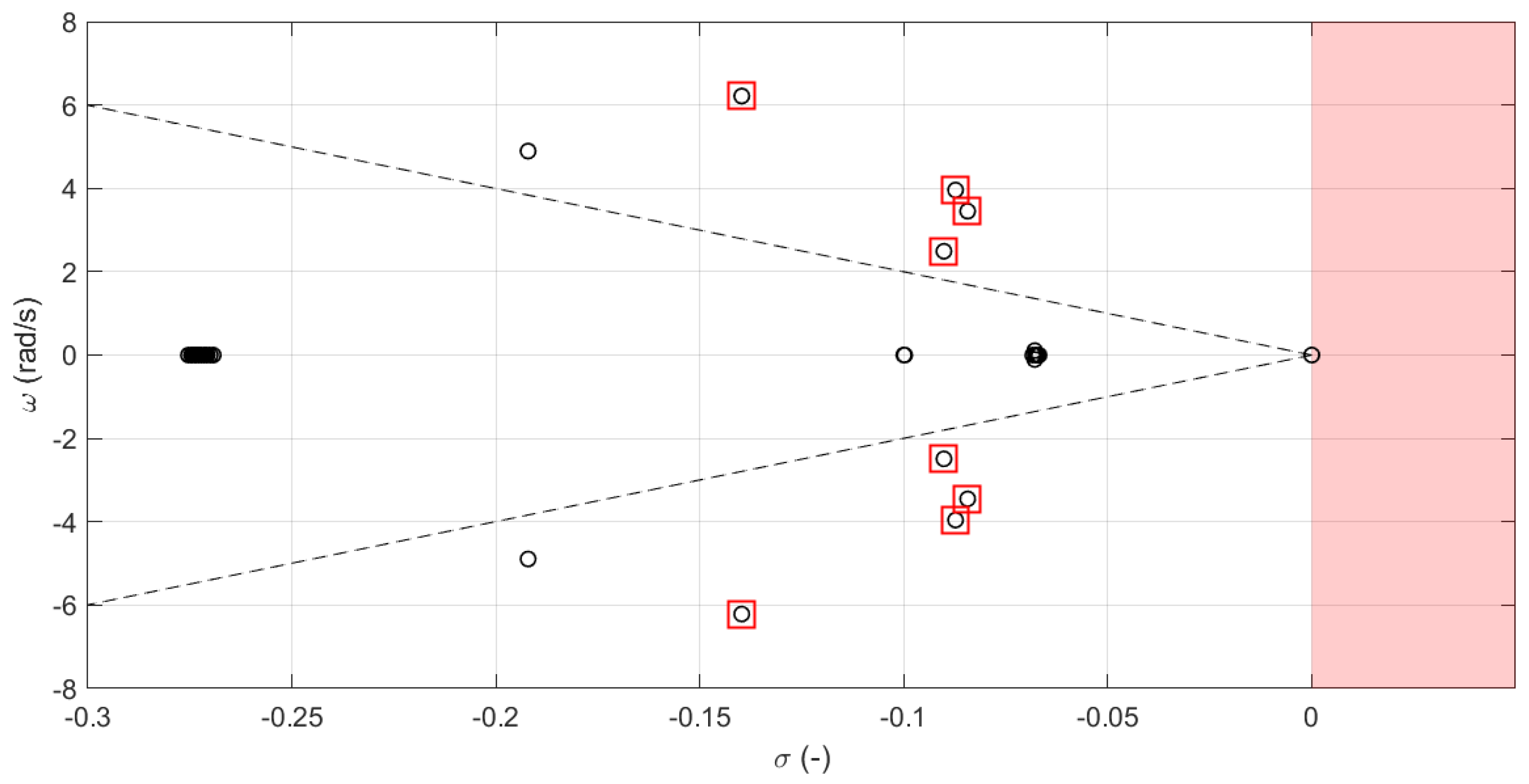
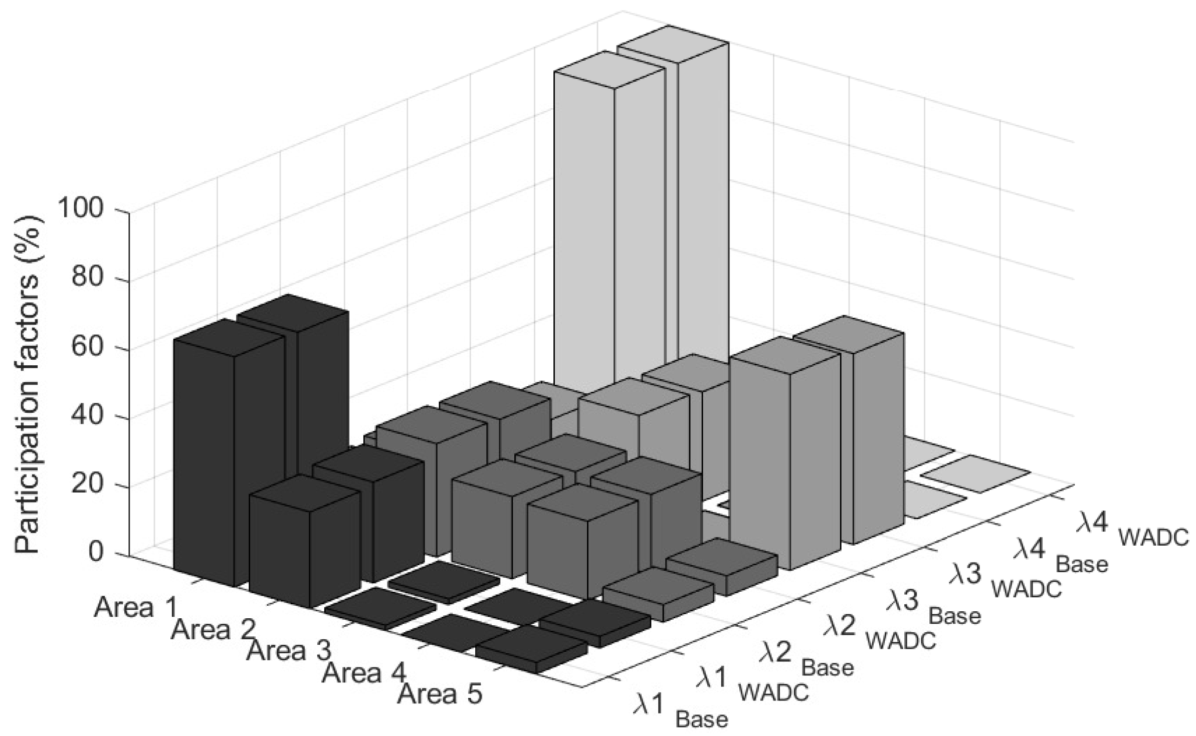
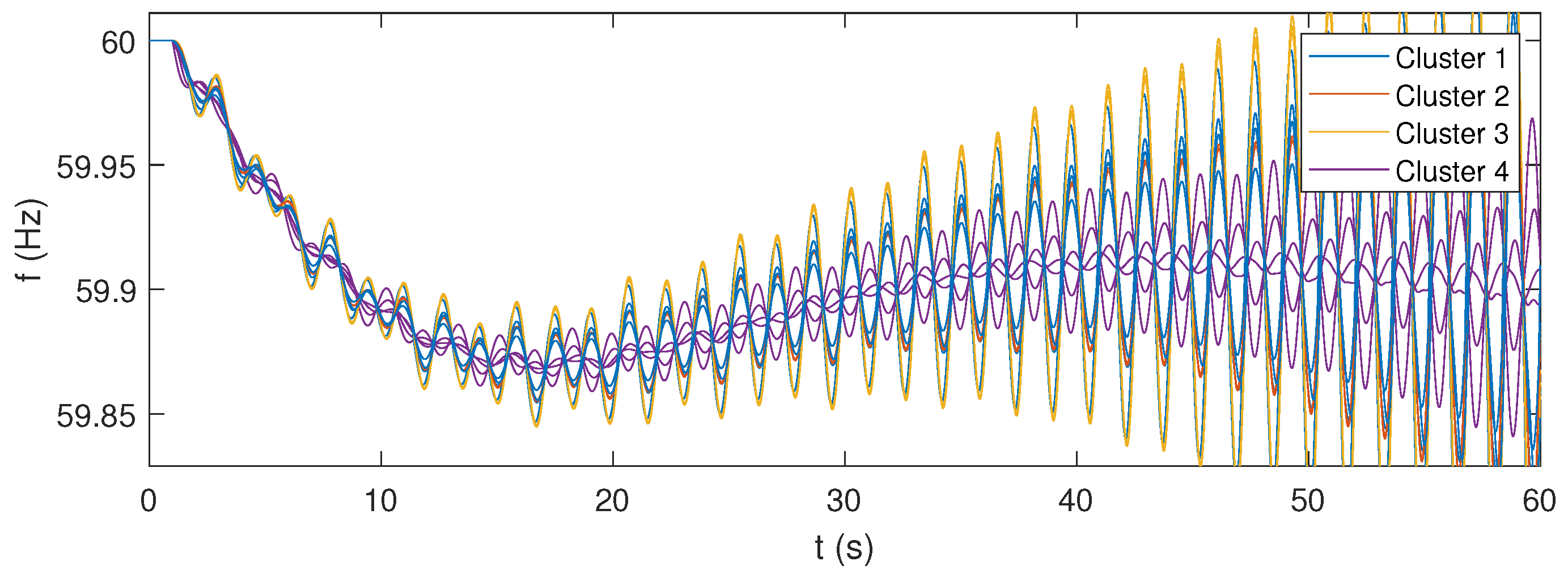
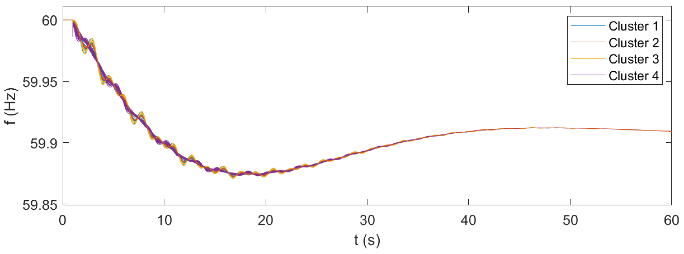
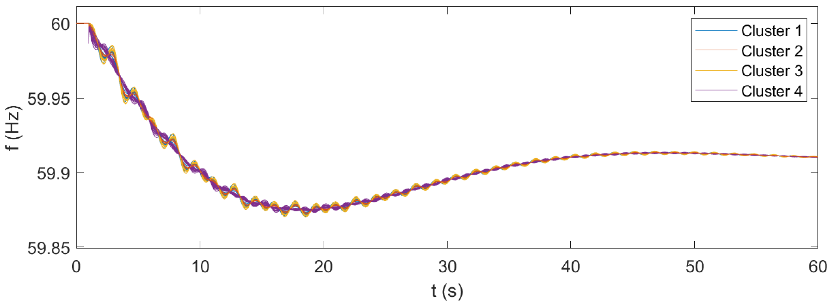
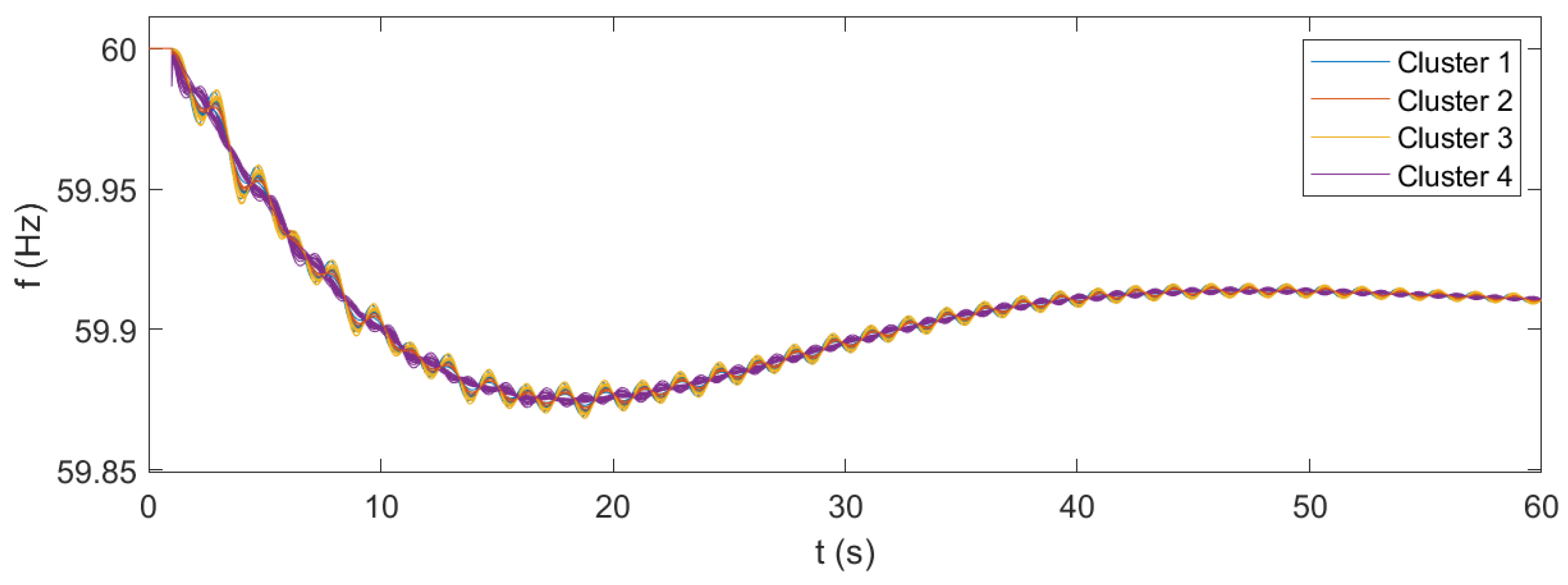
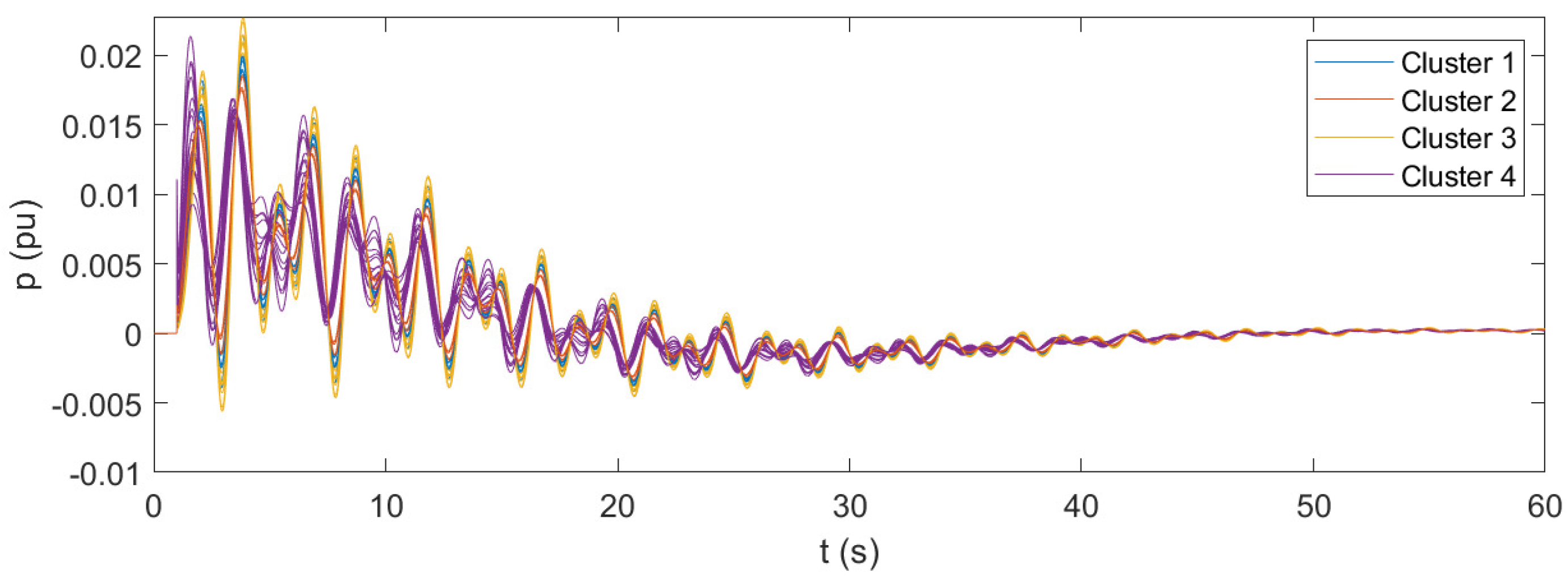
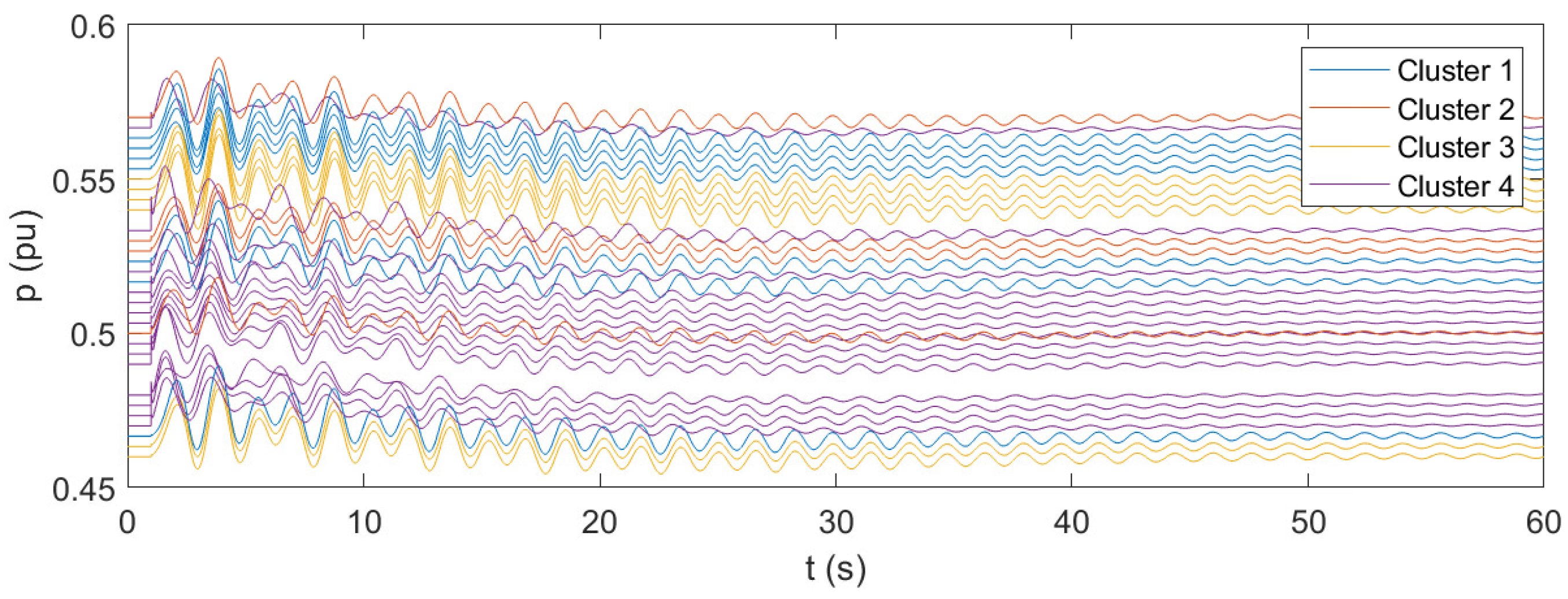
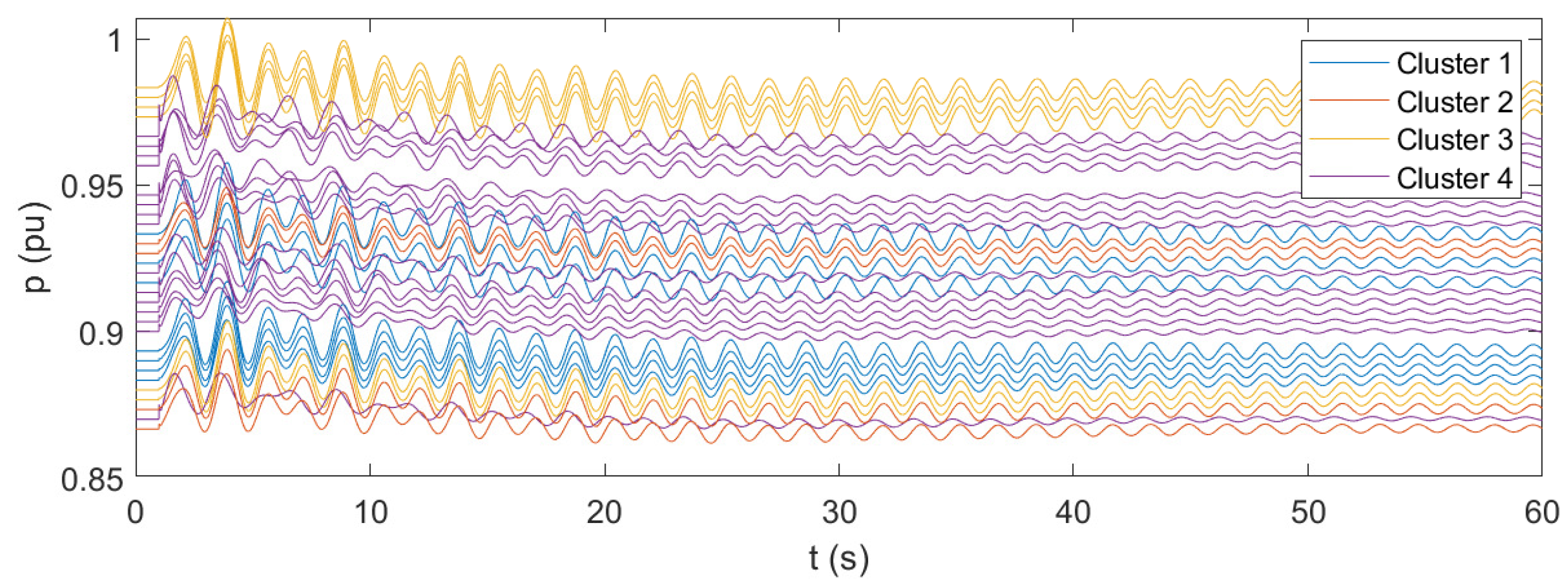
4.2. Simulation Results

The modified IEEE 68-bus benchmark system is studied through both modal analysis and time-domain simulations. The system is assumed to be under the operating conditions which critically lead to an instability phenomenon, as reported in [21]. For a more comprehensive analysis, three different operating points have been examined. In operating point #1, all microgrids are assumed to initially provide no active or reactive power. This case preserves then the original steady-state operating point of the benchmark system. In operating point #2, the microgrids are assumed to provide power corresponding to approximately half of their total capability. This case allows for checking the performance of the proposed control strategy under normally loaded conditions. In operating point #3, the microgrids are assumed to provide a significant amount of power, close to their total available capacity. This case allows for checking the feasibility of the proposed control strategy even during heavily loaded conditions.
The modal analysis is performed with a direct method, linearizing the mathematical system and then computing the eigenvalues of the state matrix. The results are shown in Figure 8 for the base case, in Figure 9 for the case of the conventional WADC, and in Figure 10 for the case of the WADC with microgrids as actuators. In the figures, the damping ratio limit of 5% is indicated with dashed lines, and the critical oscillation modes are marked with red boxes. The details of the identified modes are reported in Table 2. Between the two cases under comparison, the critical eigenvalues are associated through the participation factors, as shown in Figure 11. The participations have been aggregated per area. It can be easily observed that the associated eigenvalues have basically the same participating elements. In particular, λ 1 is an inter-area oscillation mode between Area 1 (NETS) and Area 2 (NYPS), λ 2 is a local oscillation mode within Area 1 (NEST), and λ 3 is an inter-area oscillation mode, mainly between Area 5 and Area 3 and with a small participation from Area 1. The eigenvalue λ 1 corresponds to the most critical mode, being the one with a positive real part in the base case.
According to [21], the IEEE 68-bus system exhibits a critical condition in its original configuration. A pair of complex conjugate eigenvalues is on the right-hand side of the plane, with a positive real part indicating the instability of the system. The frequency of the unstable mode is around 0.62 Hz. The application of a conventional WADC scheme can improve the dynamic performances of the system, as expected. The critical oscillation mode (eigenvalue λ 1 ) now has a positive damping ratio of 0.73%. The critical phenomenon of oscillatory instability is completely resolved. The inter-area mode at 0.63 Hz is on the left-hand side of the plane, and all the oscillation modes under examination show an increased damping ratio. When the proposed WADC with distributed microgrids as actuators is applied, the critical conditions of instability are completely resolved as well. In comparison with the conventional WADC, the proposed WADC with microgrids offers superior performances, as it can guarantee high values of damping in the system, especially for the most critical oscillation mode. It is worth observing that the participation of the microgrids in the wide-area control also contributes to enhancing the damping of oscillation modes involving external areas (eigenvalues λ 2 and λ 3 ). The application of the presented concept therefore plays a fundamental role in ensuring the stability of the system, with an overall improvement in the dynamic performance.
For the time-domain analysis, the IEEE-bus system is simulated for a power imbalance of 1000 MW in Area 2 (NYPS) at node 13. It is important to note that this work specifically addresses the slow electromechanical transients, which are typically caused by power imbalances in the system. However, severe faults and consequent phase jumps, transient stability aspects, and the potential negative impact of PLL are beyond the scope of this study. The time-domain simulation results are presented as frequency recordings at various system nodes. Figure 12 illustrates the results for the original case, while Figure 13, Figure 14 and Figure 15 correspond to the scenario where microgrids participate in the wide-area control, each corresponding to a different operating point. Additionally, for the microgrid WADC case, the active power of the microgrid resources is shown in Figure 16, Figure 17 and Figure 18, again for the three operating points, respectively. The active power values are expressed per unit of the respective microgrid’s installed capacity.
In accordance with the modal analysis, the results of the time-domain simulations of the original case show the instability of the system. The frequencies are subject to undamped oscillations, which progressively increase until the collapse of the system. In this case, the microgrids do not participate in the WADC of the system, and their active power output remains basically unchanged. The results of the time-domain simulations for the case of microgrids participating in the wide-area control confirm the fundamental support that can be achieved with the application of the proposed control architecture. The system is now stable and even has a proper damping level, as the oscillations following the disturbance are significantly contained in a few tens of seconds. The results show that the proposed microgrid WADC can provide a fundamental improvement in the stability of the system under various operating conditions. From the results, it can be also seen that the identified clusters of microgrids indeed correspond to coherent groups of resources. Even during the most critical instants of the transient, the variations Δ f of the frequencies exhibit excellent cohesion within the clusters. The additional results given in terms of active power allow for further observations: From the case corresponding to the operating point #1, where all microgrids are initially in idle mode with no provision of power, it can be seen that transient active power variations reach a maximum of about 2% of the installed capacity. This generation effort appears to be feasible in terms of the energy commitment of the resources. Additionally, the maximum values are reached for a very limited time interval, going below 0.5% of the capacity within a few seconds. The results of the system in operating point #2 show that the performance of the proposed control under normally loaded conditions are completely feasible and acceptable. In this case, where microgrids provide about half of their total power capability, the transient oscillations in the active power output rapidly fade out, reaching a steady-state condition in a few tens of seconds. From the case corresponding to operating point #3, where the microgrids provide close to their maximum available capacity, it can be observed that the transient response of the microgrids’ resources is affected by prolonged oscillations, lasting for several tens of seconds. This observation can be related to the fact that, in this operating point, the transmission lines of the system are stressed by significant power flows, resulting in worsened transient performances. The observed oscillations are not critical to the system’s stability but highlight the need for thorough assessment when operating the system under heavily loaded conditions. The results for operating point #3 also confirm that the generation sources of the microgrids can handle the transient effort required for WADC participation, even under heavily loaded conditions. These results suggest that the application of the presented WADC with microgrids as actuators can be reasonably achieved with limited effort provided by the physical resources available within the microgrid. In turn, the application of the control concept provides fundamental support to the stability of the system. However, attention should be paid to the operating point of the system, especially in case of heavily loaded conditions, since there is the possibility of sustained oscillations in the power output of the microgrid resources.

5. Conclusions

The work has introduced a novel wide-area control approach designed specifically for clustered microgrids. The proposed method addresses a critical gap by integrating microgrid assets into the stability-enhancing mechanisms of modern power systems with wide-area control architectures. By leveraging principles from flocking algorithms, the methodology ensures effective clustering, collaboration, and alignment among microgrids, enabling cohesive and coordinated control actions. The efficacy of the proposed WADC architecture is demonstrated through its application to the IEEE 68-bus standard system. The results show significant improvements in the system’s stability and in the damping of oscillations, providing fundamental support even under critical operating conditions. In particular, the inclusion of microgrids in the WADC enhanced the damping ratio of critical oscillation modes and reduced the oscillatory instability observed in the original conditions of the testing system. For the critical mode of the system, the damping ratio changes from the negative value of −1.03% in the base case to the positive value of 2.21% in the case with WADC microgrids. The damping ratios of other oscillation modes of the system are also improved, changing from values of around 1% to values of up to 3.6%. The presented research offers several opportunities for further development and investigation. Future works could extend the research by exploring the opportunity of time-varying clustering techniques for the cohesion of microgrids, the optimization of cooperation coefficients, including economic aspects, and more advanced control strategies applied to the resources of the microgrid. Further relevant aspects, such as designing a method with objective functions, could also be the focus of additional investigations. Moreover, the real-world implementation of the proposed WADC architecture with microgrids as actuators will surely pose several challenges. The realization of a robust, widespread, secure, and reliable communication infrastructure is a main aspect to address. Aspects such as cyber-security, possible loss or corruption of data packets, and time-varying latencies are fundamental points to carefully examine. At the same time, given their significance, all these aspects represent the opportunity for further specific research. Overall, the findings of this study underscore the potential of combining wide-area control with clustered microgrids to achieve coordinated and stable power systems. The analysis of different operating conditions shows that the proposed WADC control with microgrids is feasible with minimal resource commitment. Under low and normal loading conditions, transient power variations are limited and quickly stabilize. However, in the case of heavily loaded conditions and high power flows on the transmission network, prolonged oscillations might occur, highlighting the need for a thorough evaluation under different operating conditions to ensure optimal performance. The results also show that the proposed wide-area control with microgrids outperforms the conventional scheme, especially in terms of damping of the most critical oscillation modes.

Author Contributions

Conceptualization, R.M.; methodology, R.M.; validation, R.M. and J.C.V.; formal analysis, R.M.; writing—original draft preparation, R.M.; writing—review and editing, E.R.S. and J.C.V.; supervision, E.R.S. and J.M.G. All authors have read and agreed to the published version of the manuscript.

Funding

This research received no external funding.

Data Availability Statement

The raw data supporting the conclusions of this article will be made available by the authors on request.

Conflicts of Interest

The authors declare no conflicts of interest.

References

  1. Guerrero, J.M.; Vasquez, J.C.; Matas, J.; de Vicuna, L.G.; Castilla, M. Hierarchical Control of Droop-Controlled AC and DC Microgrids—A General Approach Toward Standardization. IEEE Trans. Ind. Electron. 2011, 58, 158–172. [Google Scholar] [CrossRef]
  2. Al-Saadi, M.; Al-Greer, M.; Short, M. Strategies for Controlling Microgrid Networks with Energy Storage Systems: A Review. Energies 2021, 14, 7234. [Google Scholar] [CrossRef]
  3. Mannini, R.; Eynard, J.; Grieu, S. A Survey of Recent Advances in the Smart Management of Microgrids and Networked Microgrids. Energies 2022, 15, 7009. [Google Scholar] [CrossRef]
  4. Patsalides, M.; Papadimitriou, C.N.; Efthymiou, V.; Ciavarella, R.; Di Somma, M.; Wakszyńska, A.; Kosmecki, M.; Graditi, G.; Valenti, M. Frequency Stability Evaluation in Low Inertia Systems Utilizing Smart Hierarchical Controllers. Energies 2020, 13, 3506. [Google Scholar] [CrossRef]
  5. Zuhaib, M.; Rihan, M.; Gupta, S.; Sufyan, M.A.A. Identification and suppression of low-frequency oscillations using PMU measurements based power system model in smart grid. Sci. Rep. 2025, 15, 3822. [Google Scholar] [CrossRef]
  6. Sahoo, M.; Rai, S. A method for detection of Low Frequency Oscillatory modes in power system for wide area monitoring system. Comput. Electr. Eng. 2025, 123, 110172. [Google Scholar] [CrossRef]
  7. Jeyaraj, T.; Ponnusamy, A.; Selvaraj, D. Hybrid renewable energy systems stability analysis through future advancement technique: A review. Appl. Energy 2025, 383, 125355. [Google Scholar] [CrossRef]
  8. Abouzeid, S.I.; Chen, Y.; Zaery, M.; Abido, M.A.; Raza, A.; Abdelhameed, E.H. Load frequency control based on reinforcement learning for microgrids under false data attacks. Comput. Electr. Eng. 2025, 123, 110093. [Google Scholar] [CrossRef]
  9. Bento, M.E.C. Wide-Area Measurement-Based Two-Level Control Design to Tolerate Permanent Communication Failures. Energies 2023, 16, 5646. [Google Scholar] [CrossRef]
  10. Sun, M.; Guo, Y.; Song, S. The Delay-Dependent DOFC for Damping Inter-Area Low-Frequency Oscillations in an Interconnected Power System Considering Packet Loss of Wide-Area Signals. Energies 2021, 14, 5892. [Google Scholar] [CrossRef]
  11. St. Leger, A.; Spruce, J.; Banwell, T.; Collins, M. Smart grid testbed for Wide-Area Monitoring and Control systems. In Proceedings of the 2016 IEEE/PES Transmission and Distribution Conference and Exposition (T&D), Dallas, TX, USA, 3–5 May 2016; pp. 1–5. [Google Scholar] [CrossRef]
  12. Cai, G.; Yang, D.; Liu, C. Adaptive Wide-Area Damping Control Scheme for Smart Grids with Consideration of Signal Time Delay. Energies 2013, 6, 4841–4858. [Google Scholar] [CrossRef]
  13. Mohamed, A.; Ghareeb, A.; Youssef, T.; Mohammed, O.A. Wide area monitoring and control for voltage assessment in smart grids with distributed generation. In Proceedings of the 2013 IEEE PES Innovative Smart Grid Technologies Conference (ISGT), Washington, DC, USA, 24–27 February 2013; pp. 1–6. [Google Scholar] [CrossRef]
  14. Sufyan, M.A.A.; Zuhaib, M.; Anees, M.A.; Khair, A.; Rihan, M. Implementation of PMU-Based Distributed Wide Area Monitoring in Smart Grid. IEEE Access 2021, 9, 140768–140778. [Google Scholar] [CrossRef]
  15. Ippolito, M.G.; Musca, R. A novel wide-area control for general application to inverter-based resources in power systems. Int. J. Electr. Power Energy Syst. 2024, 160, 110086. [Google Scholar] [CrossRef]
  16. Kundur, P.; Balu, N.J.; Lauby, M.G. Power System Stability and Control; McGraw-Hill: New York, NY, USA, 1994. [Google Scholar]
  17. Musca, R.; Riva Sanseverino, E.; Zizzo, G.; Giannuzzi, G.; Pisani, C. Wide-Synchronization Control for Power Systems with Grid-Forming Converters. IEEE Trans. Power Syst. 2024, 39, 4998–5007. [Google Scholar] [CrossRef]
  18. Reynolds, C.W. Flocks, herds and schools: A distributed behavioral model. In Proceedings of the Proceedings of the 14th Annual Conference on Computer Graphics and Interactive Techniques, New York, NY, USA, 27–31 July 1987; pp. 25–34. [Google Scholar] [CrossRef]
  19. Luo, X.; Li, S.; Guan, X. Flocking algorithm with multi-target tracking for multi-agent systems. Pattern Recognit. Lett. 2010, 31, 800–805. [Google Scholar] [CrossRef]
  20. Housheng Su, X.W.; Chen, G. A connectivity-preserving flocking algorithm for multi-agent systems based only on position measurements. Int. J. Control. 2009, 82, 1334–1343. [Google Scholar] [CrossRef]
  21. Benchmark Systems for Small-Signal Stability Analysis and Control; Technical Report, IEEE Power and Energy Society; IEEE Power System Dynamic Performance Committee: Piscataway, NJ, USA, 2015.
Figure 1. Microgrid schematization with power and communication systems interaction.
Energies 18 01632 g001
Figure 2. Damping matrix D with WADC application.
Energies 18 01632 g002
Figure 3. Flocking principles applied to microgrids for wide-area control.
Energies 18 01632 g003
Figure 4. Modified IEEE 68-bus benchmark system with microgrids integration.
Energies 18 01632 g004
Figure 5. Block diagram of the microgrid control and representation.
Energies 18 01632 g005
Figure 6. Block diagram of the PLL used within the microgrid control.
Energies 18 01632 g006
Figure 7. Clustering two-step procedure applied to the IEEE 68-bus system.
Energies 18 01632 g007
Figure 8. Oscillation modes of the system—original case.
Energies 18 01632 g008
Figure 9. Oscillation modes of the system—with conventional WADC.
Energies 18 01632 g009
Figure 10. Oscillation modes of the system—with microgrid WADC.
Energies 18 01632 g010
Figure 11. Participation factors of the identified critical oscillation modes.
Energies 18 01632 g011
Figure 12. Frequency of the system—original case.
Energies 18 01632 g012
Figure 13. Frequency of the system—with microgrid WADC (operating point #1).
Energies 18 01632 g013
Figure 14. Frequency of the system—with microgrid WADC (operating point #2).
Energies 18 01632 g014
Figure 15. Frequency of the system—with microgrid WADC (operating point #3).
Energies 18 01632 g015
Figure 16. Power of the sources—with microgrid WADC (operating point #1).
Energies 18 01632 g016
Figure 17. Power of the sources—with microgrid WADC (operating point #2).
Energies 18 01632 g017
Figure 18. Power of the sources—with microgrid WADC (operating point #3).
Energies 18 01632 g018
Table 1. Clusters for microgrid cohesion.
ClusterNodes (Generation)Nodes (Microgrids)
# 11, 8, 925, 26, 27, 28, 29, 52, 55
# 22, 356, 59, 60, 64
# 34, 5, 6, 720, 21, 23, 24, 67, 68
# 410, 11, 12, 1317, 33, 36, 39, 40, 44, 45, 46, 47, 48, 49, 50, 51, 53, 61
Table 2. Results of the modal analysis.
Base case
IDEigenvalueDamping ratio (%)Natural frequency (Hz)
λ 1 0.0409 ± i 3.9692 1.03 0.63
λ 2 0.0316 ± i 2.5152 1.260.40
λ 3 0.0470 ± i 3.4553 1.360.55
λ 4 0.0919 ± i 6.2008 1.480.99
WADC conventional
IDEigenvalueDamping ratio (%)Natural frequency (Hz)
λ 1 0.0288 ± i 3.9561 0.730.63
λ 2 0.0545 ± i 2.4988 2.180.39
λ 3 0.0618 ± i 3.4517 1.790.55
λ 4 0.1244 ± i 6.2082 2.000.99
WADC microgrids
IDEigenvalueDamping ratio (%)Natural frequency (Hz)
λ 1 0.0873 ± i 3.9584 2.210.63
λ 2 0.0902 ± i 2.4905 3.620.39
λ 3 0.0843 ± i 3.4509 2.440.55
λ 4 0.1397 ± i 6.2141 2.250.99
Disclaimer/Publisher’s Note: The statements, opinions and data contained in all publications are solely those of the individual author(s) and contributor(s) and not of MDPI and/or the editor(s). MDPI and/or the editor(s) disclaim responsibility for any injury to people or property resulting from any ideas, methods, instructions or products referred to in the content.

