Abstract
With the increasing prevalence of renewable energy, microgrids play a crucial role in enhancing distributed energy efficiency and system flexibility. However, the intermittent and unpredictable nature of renewable energy generation presents significant challenges for microgrid restoration and stable operation. Black-start technology, a key method for autonomous power restoration, is essential for ensuring reliable microgrid operation. Grid-forming virtual synchronous generators (VSGs), with inherent inertia support and regulation capabilities, autonomously establish the voltage, meeting the power supply demands of black-start processes. However, during the pre-synchronization of multiple distributed energy resources in black-start scenarios, rapid phase-angle adjustments can cause frequency fluctuations due to the coupling between the frequency and phase angle. This coupling often leads to frequency overshoot and decreased system stability. To address this challenge, this paper proposes an enhanced parallel restoration strategy for a multi-source black start. Optimizing phase-angle control reduces the dependency on phase-locked loops (PLLs), mitigates phase-angle difference jumps, and accelerates the pre-synchronization process. Furthermore, a linear active disturbance rejection controller (LADRC) dynamically compensates for frequency fluctuations, effectively decoupling the frequency from the phase angle. This approach improves synchronization accuracy and enhances parallel reliability among multiple distributed energy resources (DERs). Simulation results show that the proposed method suppresses frequency overshoot and system disturbances during a multi-source black start, significantly enhancing microgrid restoration capability and operational stability.
1. Introduction
The ongoing global energy transition and the widespread integration of renewable energy sources have profoundly impacted the operations of traditional power grids. Renewable energy sources such as photovoltaic (PV) and wind power, due to their inherent intermittency and variability, pose significant challenges to the stability and reliability of power systems [1,2]. In this context, microgrids have emerged as a key solution for integrating distributed energy sources, offering controllability and flexibility to address the challenges posed by renewable energy grid integration. However, traditional grid-following inverters face difficulties in adapting to systems with a growing share of renewable energy, leading to the development of grid-forming VSG technology. A VSG improves the dynamic response and operational stability of microgrids by emulating the inertia and regulatory characteristics of synchronous generators [3,4]. As power systems expand, microgrid structures and operations are becoming more complex and variable, which increases the risk of localized failures that could escalate into widespread outages or even system collapse. Microgrids must independently restore power supplies through black-start technology. VSG-based grid control strategies offer frequency and voltage support, making them ideal for the short-term voltage requirements of black-start operations. Consequently, VSG-based black-start strategies can quickly establish voltage and frequency references after a power system failure, ensuring reliable startup conditions for other devices [5,6].
In [7,8], VSG control strategies for single inverters are primarily explored, though these are often limited by capacity constraints. To enhance system capacity, a control strategy for multi-machine energy storage systems is proposed in [9]. While standalone photovoltaic systems lack black-start capability, integrating them with energy storage systems improves black-start efficiency. However, maintaining the stability of the photovoltaic system requires a high level of precision and reliability [10]. In [11,12], a sequential recovery black-start strategy is proposed, where a designated black-start microsource first establishes the system frequency and voltage before gradually synchronizing additional microsources. This approach ensures high startup reliability and a relatively simple control system structure. However, its main limitation is the underutilization of black-start capabilities, as only one microsource is designated for the black start, which limits improvements in the reliability of the microgrid power supply. Furthermore, sequential recovery requires the startup of each microsource followed by grid connection, leading to excessive time consumption that conflicts with the rapid startup demands of black-start processes [13].
In contrast, Ref. [14] proposes a parallel restoration strategy designed to achieve faster grid restoration. This approach enables multiple black-start-capable microsources to start simultaneously, forming several small subsystems. It offers rapid restoration and operational flexibility and aligns with the structural characteristics of microgrids, facilitating the swift re-establishment of power supply across the entire system. However, in parallel systems, even minor mismatches before synchronization can lead to significant disturbances [15]. Achieving simultaneous grid connection of multiple small subsystems before parallelization presents greater challenges and is more vulnerable to disturbances. In [16], the causes of oscillations induced by micro-power control mode transitions during black-start operations are investigated, and a smooth switching control method based on controller state tracking is proposed. This method enables seamless mode switching by refining the implementation of the control strategy, facilitating the rapid black start of the microgrid. However, this approach has limitations in achieving precise parallel synchronization, resulting in significant disturbances during parallel connection. Ref. [17] describes a method to synchronize microsources through power control loops; however, the synchronization time is relatively long. In [18,19,20], pre-synchronization is employed before the parallel connection of multiple microsources to eliminate amplitude and phase-angle differences in their output voltages. This approach effectively mitigates the risk of black-start failure caused by current surges resulting from amplitude or phase mismatches during parallel connection. However, it overlooks the coupling between the frequency and phase angle during pre-synchronization, making the system prone to frequency perturbations due to rapid phase-angle changes, which can significantly impact the overall parallel black-start system [21]. With the advancement of artificial intelligence algorithms, integrating intelligent algorithms with proportional–integral–derivative (PID) control has proven highly effective in addressing challenges related to strong coupling and nonlinearity in control systems [22,23]. For instance, Ref. [24] proposes an intelligent learning PID control algorithm that adapts and optimizes PID parameters to manage strong coupling between the frequency and phase angle. While this approach enhances system robustness and stability, it also presents challenges such as increased design complexity and longer computation times. Ref. [25] introduces a model predictive control (MPC)-based VSG strategy that analyzes the coupling mechanism between the frequency and phase angle. By incorporating frequency variations to adaptively adjust the weighting coefficients of MPC and dynamically modifying the power reference value of the VSG, this strategy alleviates the synchronization impact caused by frequency–phase-angle coupling to some extent. However, it faces challenges in solving the constrained optimization problems inherent to the MPC framework.
Compared with existing studies, this paper addresses several limitations in multi-machine black-start pre-synchronization strategies. While the methods in [16,17] rely heavily on multiple PLLs and suffer from phase-angle jumps, this study improves the traditional phase-angle difference measurement, reducing PLL usage and eliminating sudden phase-angle changes, thus accelerating the pre-synchronization process. Furthermore, unlike [18,19,20], which overlook the frequency overshoot caused by the coupling between the phase angle and frequency during rapid phase adjustments, this research integrates a LADRC to dynamically adjust the frequency in response to phase-angle fluctuations. By leveraging the LADRC’s strong disturbance rejection and fast dynamic response, the proposed method effectively suppresses frequency overshoot and mitigates adverse coupling effects. In contrast to the complex objective functions used in [24,25] to model frequency and phase-angle differences, the proposed approach adopts a more streamlined control algorithm, enhancing system robustness and simplifying implementation.
Building on these insights, this paper proposes an enhanced phase-angle control strategy combined with a LADRC to improve pre-synchronization accuracy and system stability. The key contributions are as follows:
- (1)
- Enhanced phase-angle measurement: By refining the phase-angle difference calculation, the proposed method reduces PLL dependence and eliminates phase-angle jumps, accelerating pre-synchronization.
- (2)
- Frequency–phase-angle decoupling: The integration of the LADRC mitigates the coupling effect between the frequency and phase angle, effectively suppressing frequency overshoot and ensuring smoother dynamic responses.
- (3)
- Improved system robustness: The simplified control strategy avoids complex objective functions, striking a balance between synchronization speed and system stability.
Ultimately, this strategy enhances synchronization accuracy among black-start microsources, reduces disturbances during parallel grid connection, and strengthens the microgrid’s recovery capability, offering a practical solution to the challenges of multi-machine black start.
2. Multi-VSG Black-Start Strategy
2.1. Comparison of Grid Recovery Strategies
Orphaned grid black start refers to the independent operation of a power system initiated by self-starting units, without the support of an external grid. The process involves progressively restoring the system by gradually expanding the recovery scope until full restoration is achieved. This typically occurs after an initial startup or following a complete shutdown due to faults.
The black-start process consists of three main stages [26]: the startup of black-start microsources, grid restoration, and load casting. Among these, grid restoration is a critical component, typically classified into two types, serial and parallel restoration, as summarized in Table 1.

Table 1.
Comparison of grid recovery strategies.
In microgrid black-start restoration, serial recovery begins with a single black-start microsource to establish the reference voltage, followed by the sequential synchronization of other microsources. This method is simple but slower, making it challenging to meet fast power supply demands. In contrast, parallel recovery activates multiple microsources simultaneously under a load, with subsystems pre-synchronized for stable operation, accelerating recovery. However, pre-synchronizing multiple subsystems is more complex, and small deviations can significantly affect stability, increasing synchronization performance requirements. Therefore, improving the pre-synchronization performance of multiple black-start microsources is indispensable for faster grid recovery and ensuring system safety.
To meet the isolated microgrid black-start requirements, multiple black-start microsources are precisely controlled by VSGs, providing stable frequency and voltage support. Additionally, the black-start microsource VSG’s DC side employs a photovoltaic energy storage strategy, ensuring sufficient capacity and effectively stabilizing the DC bus voltage.
2.2. Multi-VSG Black-Start Control
2.2.1. VSG Networking/Parallel Modeling
The block diagram of the VSG control structure is shown in Figure 1. Udc is the DC-side voltage; L, RL and LC, C are the filter impedance and filter capacitance, respectively; Ui (i = a, b, c) is the three-phase output voltage of the inverter side; i (i = a, b, c) is the output current of the inverter; and Lg and Rg constitute the grid impedance.
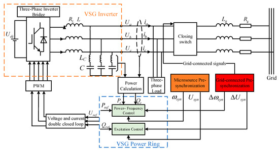
Figure 1.
VSG control schematic diagram.
The VSG Power Ring mainly contains active and reactive loops, which simulate the primary voltage regulation and primary frequency regulation characteristics of synchronous generators, respectively. In VSG active-frequency control, virtual inertia and damping are implemented to emulate the external characteristics of synchronous generators, offering voltage and frequency support to the system.
- (1)
- Active-Frequency Control:
The active-frequency control equation for the VSG is expressed as follows [27]:
The VSG governing equation is
In the above equation, J represents the virtual inertia, and D denotes the damping coefficient. Te and Tm correspond to the electromagnetic and mechanical torques, respectively, while Pm and Pe refer to the mechanical and electromagnetic power. ωn is the rated angular velocity, and ω is the actual angular velocity. θ is the power angle. The active power reference is denoted by Pref, and Kp represents the droop coefficient. Figure 2 illustrates the block diagram of the power–frequency control system.
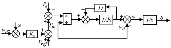
Figure 2.
Power–frequency control block diagram.
However, the change in frequency affects the terminal voltage of the generator through electromagnetic coupling, so it is necessary to further introduce the voltage-reactive power equation to regulate the excitation voltage so as to maintain the voltage stability of the system. The voltage-reactive power equation regulates the terminal voltage and reactive power by controlling the excitation voltage to ensure that the system voltage is stabilized while the frequency is regulated.
- (2)
- Voltage-Reactive Control:
The reactive power-voltage equation for VSG is
The reactive power reference is denoted by Qref. U0 and Un represent the rated and actual voltages, respectively, while Ku and Kq denote the droop and integration coefficients, respectively. Figure 3 illustrates the block diagram of the excitation control system.
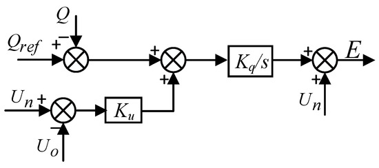
Figure 3.
Excitation control block diagram.
The desired voltage is achieved by adjusting the voltage amplitude and phase through the active and reactive power control loops, respectively. The output is then processed via a voltage–current dual closed-loop system to generate the final PWM waveform.
During grid restoration, pre-synchronization among black-start microsources generates the frequency perturbation ωsyn and voltage perturbation Usyn required for frequency and excitation control, enabling voltage synchronization between microsources and ultimately forming a parallel network. Following the islanded black start, the synchronized microsource voltages are further aligned with the grid voltage by generating additional frequency perturbation Δωsyn and voltage perturbation ΔUsyn through pre-synchronization. These perturbations are superimposed onto the active and reactive power loops.
Therefore, in order to improve the black-start capability, the analysis of the pre-synchronization mechanism between black-start microsources is essential.
2.2.2. Multi-Machine Pre-Synchronized Phase-Angle Control Strategy
If three photovoltaic energy storage VSGs are used as black-start microsources, VSG1 is designated as the main reference power supply to establish the reference voltage. Before synchronization, the other two VSGs must align their output voltages with VSG1 to avoid impacts during system integration that could disrupt the black-start process. Due to parallel recovery, the three black-start microsource VSGs operate independently before being integrated in parallel. VSG2 and VSG3 are synchronized with VSG1 individually, with each synchronization process occurring independently. The overall system microsource synchronization can be compared to the pre-synchronization process of a single machine.
In islanded operation, differences in angular frequency, phase angle, and amplitude may exist between the output voltages of VSGi (i = 2, 3), Vabci, and the output voltage of VSG1, Vg. These differences can cause an instantaneous voltage disparity at the common coupling point (PCC), with a peak value approximated at 2 U. The voltage difference is calculated as follows [28]:
The deviations in the components of the two voltages are governed by nonlinear control, resulting in a complex process due to the coupling between the frequency and phase angle. In contrast, amplitude control is linear. Thus, the critical aspect of pre-synchronization is managing the coupling between the frequency and phase angle.
During multi-machine pre-synchronization, the output voltage of VSGi synchronously tracks the voltage of VSG1. The voltage vector diagram illustrating this tracking process is shown in Figure 4.
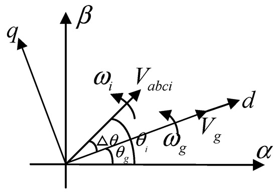
Figure 4.
A vector diagram of the pre-synchronization process.
As shown in the figure, the two voltages rotate at their respective angular frequencies, causing a time-varying Δθ. If Δθ can be constrained within an allowable range and the linear adjustment of the amplitude is appropriately performed, the two vectors can coincide, achieving pre-synchronization [18,19,20]. The block diagram is shown in Figure 5.
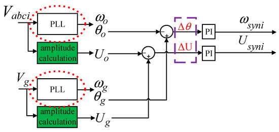
Figure 5.
The frequency and phase angle are adjusted at the same time.
Using a conventional PLL to obtain the phase angle presents challenges. Not only is the PLL complex to control, but it also causes Δθ jumps when directly extracting Δθ. The voltage phase varies from 0 to 2π, with a discontinuity from 2π back to 0 in each cycle. For example, in Figure 6, at time t1, θg reaches a maximum of 2π and then jumps to 0 at the next moment. However, due to the lag of θi, it has not yet reached its peak, causing to decrease by 2π, and thus, Δθ becomes Δθ−2π between t1 and t2.
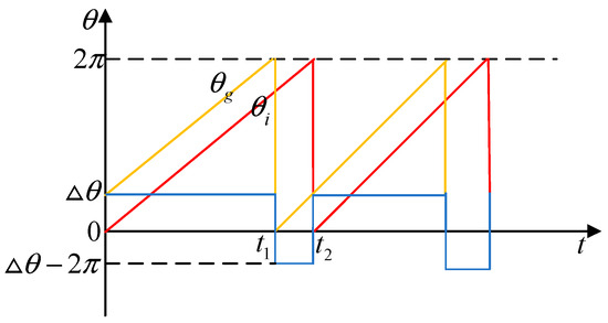
Figure 6.
Phase-angle difference jump mechanism.
Jumps in the sign of Δθ alter the original adjustment trend and prolong the synchronization adjustment time. Thus, the impact of Δθ jumps can be eliminated by enhancing the phase-angle controller.
To address the over-reliance on the PLL and Δθ, the conventional phase-angle difference acquisition method has been improved, and a new phase-angle control variable has been introduced.
Since sin(Δθ ± 2π) = sinΔθ, when Δθ increases or decreases by 2π, sinΔθ remains continuous without any sign jumps.
To verify the feasibility of this scheme, the approximation scheme errors and impacts are analyzed. Using the Taylor expansion, sinΔθ can be expressed as follows:
The approximation error E is given by
For small Δθ, the higher-order terms can be neglected, making the substitution sinΔθ ≈ Δθ valid. However, as Δθ increases, the nonlinear terms introduce a compression effect, causing the input to the controller to shrink. This shows that when Δθ is small, the difference between sinΔθ and Δθ mainly comes from the cubic nonlinear term. The characteristics of this error are as follows:
- (1)
- Negligible for small angles (e.g., <10°);
- (2)
- Rapidly increasing for larger angles (e.g., >30°), following a cubic relationship.
The PI controller takes sinΔθ as input and outputs the frequency compensation Δω:
Introducing the error E, we obtain
Breaking it down into the traditional method and the error contribution,
The frequency compensation error is
By substituting ,
Assuming Δθ changes linearly over a short period,
The integral becomes
The final error expression is
This indicates that the instantaneous error term is proportional to the cube of Δθ. Accumulated Error Term: The error accumulation is more pronounced as time grows linearly and Δθ increases.
Integrating Δωerror,
From the above equation, we can see that the first-order term increases linearly with time, affecting the transient response, and the second-order term shows that synchronization errors accumulate at an accelerating rate over time.
Let us compute the instantaneous and cumulative errors for two cases.
When Δθ = 10° (0.1745 rad), t = 0.1 s,
When Δθ = 30°(0.5236 rad), t = 0.1 s,
From the above error results, we know that the approximation sinΔθ ≈ Δθ is highly accurate for angles smaller than 10°, with minimal impact on synchronization. When Δθ exceeds 30°, the cubic nonlinear term causes rapid error growth, leading to frequency compensation deviations and accumulated synchronization errors.
To avoid the impact of Δθ sign jumps on the pre-synchronization control process, pre-synchronization control can also be implemented by replacing sinΔθ with Δθ. The specific formula is
The schematic diagram is illustrated in Figure 7.
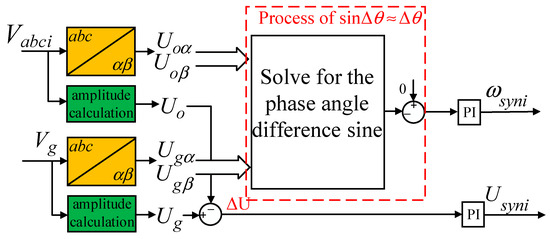
Figure 7.
Improved phase-angle pre-synchronization control strategy.
Although the improved phase-angle control method significantly accelerates pre-synchronization, it overlooks the coupling between the frequency and phase angle.
For VSGi (i = 2, 3), the relationship between the frequency and phase angle is described by
This equation indicates that frequency changes directly affect the phase-angle difference. The output active power Pei of VSGi is related to the phase-angle difference by
Rapid changes in cause fluctuations in Pei, which in turn affect the frequency dynamics of VSGi:
In a discrete period Ts, the relationship between the phase angle and angular frequency can be expressed as follows:
Thus, from the above frequency–phase-angle coupling relationship, it follows that when sinΔθ ≈ Δθ rapidly converges to zero, it induces rapid frequency fluctuations, leading to frequency overruns. During the parallel black start of multiple machines, unresolved frequency disturbances can cause significant impacts at the moment of gate closure and paralleling. In severe cases, this may lead to a black-start failure of the microgrid.
2.2.3. LADRC Adaptive Adjustment
Traditional PI controllers struggle to handle nonlinear control issues, such as frequency and phase-angle adjustments. Therefore, LADRC control is introduced due to its strong immunity and fast dynamic response, enabling rapid adjustments to suppress frequency fluctuations, thus minimizing overshoot or deviation.
The second-order LADRC consists of a linear extended state observer (LESO) and linear state error feedback (LSEF). The entire LADRC is integrated into the active loop of VSGi (i = 2, 3) to regulate the output frequency. The frequency output dynamics can be modeled as a second-order linear system. In traditional VSG power–frequency control, the nominal angular frequency ωn serves as the reference frequency. The power–frequency control loop of the VSG adjusts the power compensation based on the deviation between the nominal angular frequency and the actual output angular frequency, thereby regulating the system frequency. However, this control method, relying on a fixed reference frequency, exhibits a limited ability to suppress external disturbances, especially under large disturbances. Since ωn remains constant, frequency deviations may accumulate over time.
To address this issue, the LADRC is introduced to replace the fixed nominal angular frequency ωn as the dynamic reference, forming a closed-loop connection with the system’s output frequency. Specifically, the LESO in the LADRC continuously observes the total disturbance within the system, including unmodeled dynamics and external disturbances, dynamically estimating the frequency state and its variation. Simultaneously, linear state error feedback (LSEF) calculates the frequency deviation and, combined with the observed disturbance, generates a dynamic compensation signal, u. This compensation signal adaptively corrects frequency deviations and rapidly mitigates the impact of disturbances, ensuring the dynamic stability of the frequency. Figure 8 shows the block diagram of LADRC-VSG adaptive control.
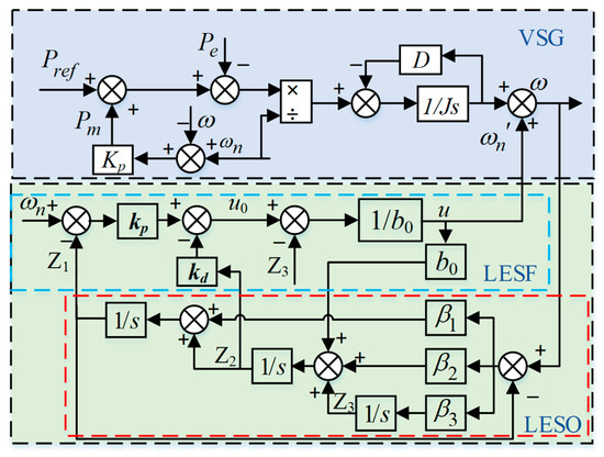
Figure 8.
Block diagram of LADRC-VSG adaptive control.
The reference frequency ωn represents the original expected value. The system output corresponds to the actual frequency. b0 denotes the system gain.
The second-order LADRC system comprises the LESO and LSEF [29]. Consider a linear second-order single-input, single-output system object as follows:
In the equation, u and ω represent the system’s input and output, respectively. r denotes the external disturbance, a1 and a2 are the system parameters, and b is the system gain, approximated as b ≈ b0, where b0 is the nominal value. Defining x1 = ω, x2 = ω, and x3 = f(ωn,,r) = −a1 − a2ω + r + (b − b0)u as the total disturbance, which accounts for internal system uncertainties and external disturbances, this leads to the equation of state as follows:
In the equation, x1 and x2 represent the state variables of the system.
During the pre-synchronization of the three VSG black-start microsources, VSG1 serves as the reference power supply, and VSGi (i = 2, 3) is synchronized with VSG1 using independent LADRC frequency control.
It should be noted in particular that, before the closing of the gate, VSGi (i = 2, 3) has only independent coupling with VSG1, and at this time, there is no direct coupling between VSGi (i = 2, 3) and VSG1, and thus, the total perturbation x3 mainly originates from the following:
- (1)
- VSG1’s own frequency perturbation d1(t).
The output frequency of VSG1 may fluctuate slightly due to external perturbations or self-regulation. This affects the pre-synchronization process of VSGi (i = 2, 3), causing them to require additional frequency adjustment to match VSG1.
- (2)
- Frequency overshoot due to frequency–phase-angle coupling during pre-synchronization of VSGi (i = 2, 3) and VSG1.
Due to the inherent coupling between the frequency and phase angle, VSGi (i = 2, 3) may experience transient frequency overshoot during frequency adjustment. This overshoot depends on the control strategy for pre-synchronization and the LADRC control parameters. According to the kinetic equation, x3 can be decomposed into the following three parts.
Here, is the frequency perturbation caused by the rapid phase angle, since VSGi (i = 2, 3) needs to adjust the phase angle gradually to match VSG1, and reflects the rapid change in the phase angle during the adjustment process. is the frequency shift caused by the accumulation of phase-angle deviations, which causes a steady-state error in the frequency if there is a persistent deviation of the phase angle of VSGi (i = 2, 3) from that of VSG1. d1(t) denotes the self-wavering fluctuation of VSG1, and small perturbations of VSG1 will be transmitted through the synchronization process of VSGi (i = 2, 3) and cause the control system to be inaccurate. d1(t) denotes the frequency shift caused by the phase-angle deviation. Due to self-fluctuations, small perturbations of VSG1 will be transmitted through the VSGi (i = 2, 3) synchronization process and lead to additional adjustments in the control system.
The LESO primarily estimates the system’s state (frequency), its rate of change, and external disturbances. The mathematical formulation of a LESO for a second-order system is as follows:
Z1, Z2, and Z3 represent the current frequency estimate, the rate of change in frequency, and the total disturbance observation, respectively. β1, β2, and β3 are the observer gains, responsible for adjusting the observer’s sensitivity to states and the speed of response. As can be seen, when Z1 can accurately track the output ω, the error ω − Z1 will converge to 0, and thus, Z3 ≈ 0. During the dynamic response process, Z3 will be continuously updated to reflect the real-time total perturbation x3 of the system; i.e., Z3 is actually an online estimate of x3 in real time, which is used for the estimation of the frequency–phase-angle coupling, as well as the total perturbation triggered by the uncertain fluctuations within VSG1 itself, and finally, the effect of Z3 is reflected in the control input u, which is adjusted in real time by PD control.
Linear state error feedback (LSEF) is responsible for regulating the system’s control input via state feedback to achieve frequency regulation. Based on the LADRC control strategy, the input u guides the frequency toward the target value while suppressing overshoot. This process can be mathematically expressed as follows:
where kp and kd are the pending parameters of the PD controller, and kp and kd can be expressed as follows:
where ωc is the controller bandwidth; ξ is the damping ratio. The characteristic equation of the LESO can be expressed as follows:
where the complex frequency s = jw. Choosing the ideal characteristic equation λ(s) = (s + ω0)3, we have
where ω0 is the observer bandwidth.
According to Figure 8, the closed-loop transfer function is deduced as follows:
Among them,
Therefore, in order to determine the system’s PD gain coefficient, this study thoroughly investigates the impact of the ωc parameter on system performance.
As can be seen from Figure 9, with the increase in ωc, since the closed-loop poles gradually move away from the imaginary axis, the response speed of the system also increases accordingly. At the same time, the damping of the system does not exhibit a monotonic characteristic. When ωc is at its minimum value, the system damping reaches its maximum. Therefore, ωc should not be set too large; otherwise, it will lead to excessive overshoot. As shown in Figure 10, with the increase in ωc, the phase margin in the middle- and low-frequency bands increases, the dynamic performance of the system is improved, and the disturbance is well suppressed. Therefore, the value of ωc can be increased within a certain range until the system noise reaches its minimum, which helps enhance the system’s anti-interference capability. Once the parameter ωc is determined within the specified range according to the system stability requirements, the specific values of the proportional gain Kp and the derivative gain Kd can be accurately determined by virtue of the established relationship between ωc and the gain coefficients of the PD controller.
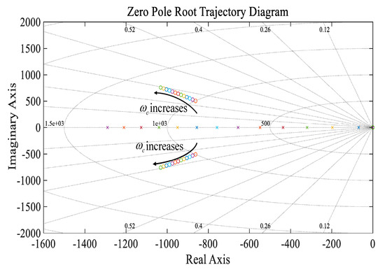
Figure 9.
The root locus diagram of E(s)/X(s) when ωc increases.
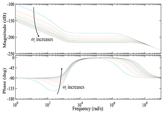
Figure 10.
The Bode diagram of F(s)/X(s) when ωc increases.
3. Microgrid Black-Start Process
Figure 11 illustrates the overall control block diagram for the black-start process. The main line parameters are mentioned in Figure 3. Uxi (x = a, b, c; I =a, b, c) denotes the three-phase output voltage on the inverter side, and ixi (x = a, b, c; i = a, b, c) is the inverter’s output current. VSGi (i = 2, 3) incorporates LADRC-based frequency modulation and an improved phase-angle control pre-synchronization strategy. The parameters ωsyn1, Usyn1, ωsyn2, and Usyn2 represent frequency and voltage compensation, respectively, to achieve synchronization with VSG1. Finally, Δωsyn and ΔUsyn provide frequency and voltage compensation during integration with the main grid.
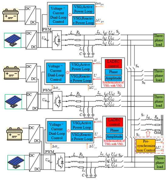
Figure 11.
Overall black-start control block diagram.
Figure 12 illustrates specific implementation details of the control schematic block diagram in Figure 11. It is roughly divided into four links: Microsource Initiation, Parallel Network Operation, Load Shedding, and Pre-synchronized Grid Connection.
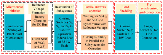
Figure 12.
A detailed diagram of the control principle.
4. Discussion of Black-Start Performance Analysis
To evaluate the effectiveness of the proposed multi-machine black-start strategy, a simulation model was developed in Simulink. The model verified the strategy’s capability to rapidly restore the voltage. The simulation involved three photovoltaic-storage VSGs with equal initial capacities before the black start was completed. Following grid connection, the capacities were adjusted to a 4:2:1 ratio. A parallel recovery strategy was implemented, with a total simulation time of 2 s. Loads were introduced at 0.1 s intervals, switches were closed for parallel operation at 0.4 s, and the remaining load was connected at 0.5 s. The system simulation parameters for each VSGi (i = 1, 2, 3) are detailed in Table 2.
Table 2.
Simulation parameters.
4.1. Traditional Phase-Angle Control for Multi-Machine Black Start
The traditional pre-synchronization control method is first applied to the multi-machine black-start process to verify the zero-start voltage boost. Figure 13 and Figure 14 show the A-phase AC bus voltage and current established by the three VSGs. During the voltage buildup of VSG2 and VSG3, voltage distortion occurs under traditional phase-angle control. Once stability is achieved, the voltage quality meets the required standards. To prevent system shutdown from excessive load at the early stage of the black start, a load is introduced at 0.1 s. Although the synchronization of the microsources is relatively slow, they eventually achieve parallel operation. Current generation begins at 0.1 s, with distortion observed during the parallel connection, and increases after 0.5 s as the load switches. Following the islanded black start, the system transitions to grid-connected operation, resulting in current variations due to capacity changes. As shown in Figure 15, voltage synchronization is completed at approximately 0.985 s, validating the effectiveness of the zero-start voltage boost in the black-start simulation.
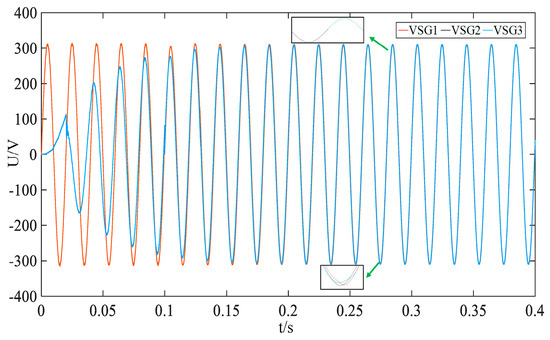
Figure 13.
Black-start microsource A-phase voltage under conventional phase-angle control.
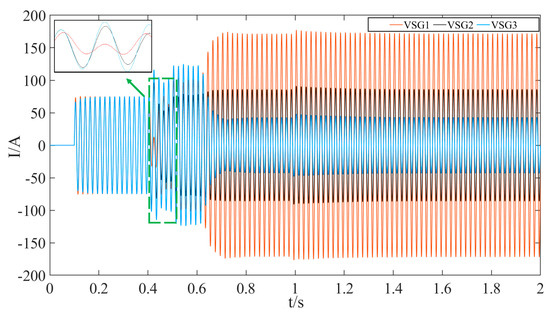
Figure 14.
Black-start microsource A-phase current under conventional phase-angle control.
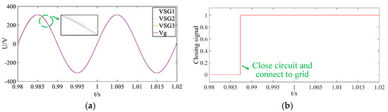
Figure 15.
Voltage synchronization for black-start islanding and grid connection under traditional phase-angle control: (a) grid voltage synchronization; (b) grid-connected closing signal.
Figure 16 and Figure 17 illustrate the frequency and power waveforms during the black-start process. Owing to the limitations of traditional phase-angle control in pre-synchronization, both frequency and power experience noticeable fluctuations immediately after the parallel connection at 0.4 s. Nevertheless, the system gradually stabilizes, ultimately achieving a steady-state operation.
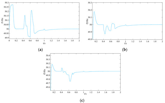
Figure 16.
Black-start microsource frequency waveform under conventional phase-angle control: (a) main reference microsource VSG1 frequency; (b) microsource VSG2 frequency; (c) microsource VSG3 frequency.
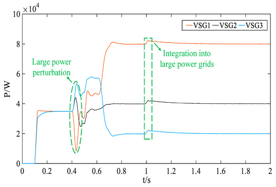
Figure 17.
Black-start microsource power waveform under conventional phase-angle control.
4.2. Improved Phase-Angle Control for Multi-Machine Black Start
Compared with the conventional phase-angle control strategy, the improved phase-angle control further enhances the black-start capability by improving the pre-synchronization performance among multiple black-start microsources.
Figure 18 shows that with improved phase-angle control during pre-synchronization, the three microsources achieve rapid synchronization, minimizing disturbances during grid connection. After load switching at 0.5 s, the current increases, and grid integration is completed at approximately 0.8 s, with fluctuations due to capacity changes, as illustrated in Figure 19. Compared to traditional methods, both voltage and current performance are notably enhanced. Figure 20 further demonstrates that the islanded black-start system achieves faster grid connection than the conventional phase-angle control approach.
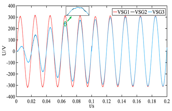
Figure 18.
Black-start microsource A-phase voltage under improved phase-angle control.
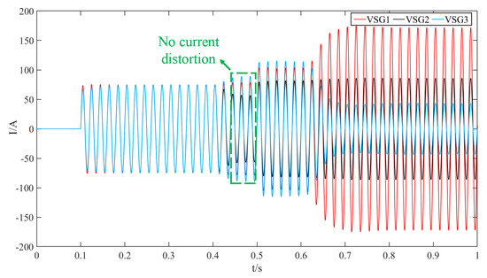
Figure 19.
Black-start microsource A-phase current with improved phase-angle control.
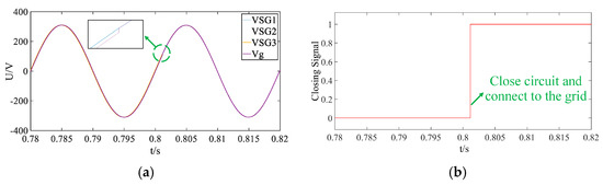
Figure 20.
Voltage synchronization for black-start islanding and grid connection under improved phase-angle control: (a) grid voltage synchronization; (b) grid-connected closing signal.
While the improved phase-angle control during pre-synchronization accelerates synchronization and enhances voltage and current quality in the black-start process, the rapid adjustment of phase angles in VSG2, VSG3, and the main microsource induces frequency overshoot during their parallel connection due to the coupling between the frequency and phase-angle. As shown in Figure 21, the main reference source experiences minimal disturbance at the moment of synchronization. However, Figure 22 reveals significant power fluctuations when VSG2 and VSG3 are connected in parallel, which, if left unregulated, could result in black-start failure.
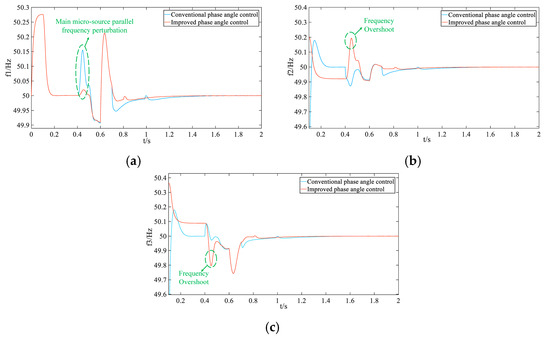
Figure 21.
Comparison of black-start microsource frequency waveforms before and after improved phase-angle control: (a) main reference microsource VSG1 frequency; (b) microsource VSG2 frequency; (c) microsource VSG3 frequency.
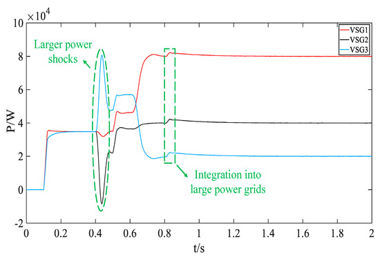
Figure 22.
Black-start microsource power waveform with improved phase-angle control.
4.3. LADRC Decoupled Control of Multi-Machine Black Start
This study aims to enhance the voltage and current quality during the black-start process while preventing black-start failure due to the frequency overshoot of microsources in the pre-synchronization process with improved phase-angle control. The proposed solution addresses the issue of frequency overshoot caused by rapid changes in the phase-angle difference during the synchronous parallel connection of VSG2 and VSG3 with the main reference microsource, VSG1, by introducing LADRC control. The frequencies of VSG2 and VSG3 are reduced as the total system perturbation is adaptively adjusted. Once the perturbation is reduced, the overall system disturbance decreases, and the frequency of the main reference source, VSG1, is improved when the three VSGs are synchronized in parallel. Figure 23 compares the microsource frequency waveforms under LADRC decoupling control and improved phase-angle control. After achieving stable frequency control, the phase-angle control of the micro-source synchronization becomes smoother and more controllable, leading to faster stabilization. Figure 24 illustrates the phase-angle difference control compared to the improved phase-angle control.
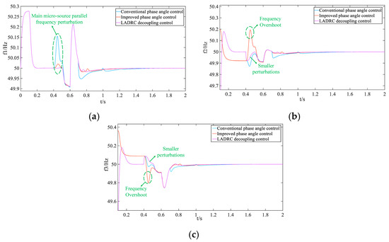
Figure 23.
Comparison of black-start microsource frequency waveforms before and after LADRC decoupling control: (a) main reference microsource VSG1 frequency; (b) microsource VSG2 frequency; (c) microsource VSG3 frequency.
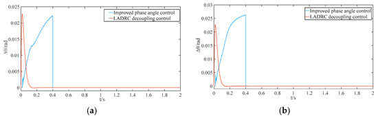
Figure 24.
Comparison of phase differences before and after LADCRC decoupling control: (a) phase difference between VSG2 and main reference power supply; (b) phase difference between VSG3 and main reference power supply.
If the frequency and phase angle are not promptly controlled during the parallel networking of black-start microsources, instantaneous power fluctuations can severely impact black-start performance. Figure 25 compares the output power under LADRC decoupling control, which mitigates the coupling effect between the frequency and phase angle, resulting in smoother instantaneous power synchronization. This accelerates and stabilizes parallel recovery, enhancing system robustness. As shown in Figure 26, the system connects to the grid approximately 0.75 s after completing the islanded black start, boosting system capacity and reducing the risk of prolonged island operation.
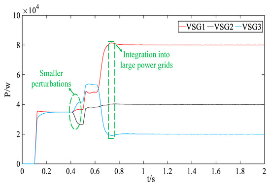
Figure 25.
Black-start microsource power waveform with LADRC decoupling control.
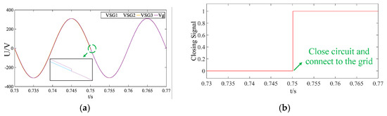
Figure 26.
Voltage synchronization for black-start islanding and grid connection under LADRC decoupling control: (a) grid voltage synchronization; (b) grid-connected closing signal.
4.4. Engineering Realization Discussion
Although the LADRC decoupling control strategy proposed in this paper effectively suppresses the frequency–phase-angle coupling problem during the VSG black-start microsource pre-synchronization process in theory and through simulation, it may still face the following challenges in practical microgrid applications:
- (1)
- Computational Latency and Complexity: The LADRC relies on a LESO for the real-time observation and compensation of the system frequency and disturbances. However, in practical microgrids, constrained by hardware computational capabilities and high-speed data sampling conditions, a high-order LESO may introduce computational delays, thereby compromising frequency compensation effectiveness. To address this, reduced-order extended state observers (RESOs) can be adopted to simplify computational complexity, while distributed control strategies can be integrated to alleviate central control burdens and reduce data processing and transmission delays, thereby enhancing the timeliness of compensation signals.
- (2)
- Hardware Implementation and Communication Architecture Compatibility: VSGs are typically distributed across various nodes in a microgrid, requiring the frequency, phase angle, and other data to be transmitted via communication links to a central controller or among themselves. However, issues such as communication delays and packet loss may cause dynamic compensation signals from the LADRC to lag or fail, adversely affecting pre-synchronization performance. Therefore, in engineering implementations, it is essential to optimize hardware architecture and communication protocols, such as adopting edge computing-based LADRC control units to reduce reliance on remote data, ensuring real-time and stable regulation capabilities of compensation signals.
5. Conclusions
This paper presents an enhanced pre-synchronization strategy integrating optimized phase-angle control with LADRC adaptive regulation to improve synchronization accuracy and reliability in multi-microsource parallel recovery during a black start. By minimizing PLL dependency and avoiding phase-angle jumps, the approach accelerates synchronization while introducing a LADRC for the real-time compensation of frequency fluctuations. This suppresses frequency overshoot from frequency–phase-angle coupling, enabling precise and coordinated optimization of both parameters. Finally, a comparison of the voltage and current quality generated by the three strategies during the black-start process, along with the frequency characteristics of the parallel networking process of black-start microsources, demonstrates that the proposed strategy effectively reduces the impacts of parallel connection, improves synchronization performance, and enhances the resilience of the microgrid during the black-start process.
However, practical implementation necessitates addressing computational latency and communication architecture compatibility. Future research could optimize LESO computational complexity by introducing reduced-order observers (RESOs), leverage distributed control and edge computing to minimize latency, and enhance communication link robustness to improve microgrid dynamic stability.
Author Contributions
Z.R. developed the methodology, contributed to the design of the control strategy, and implemented the simulation model. S.D. collected and analyzed the data. All authors discussed the results, reviewed the manuscript, and approved the final version for publication. All authors have read and agreed to the published version of the manuscript.
Funding
This work was funded by the 2022 Jiangsu Carbon Peak and Neutrality Technology Innovation Special Fund (Industrial Foresight and Key Core Technology Research) “Research and Development of Key Technologies for Grid Integration Operation and Control of Renewable Energy Sources” (grant Number: BE2022003-3).
Data Availability Statement
The original contributions presented in the study are included in the article. Further inquiries can be directed to the corresponding author.
Conflicts of Interest
Author Yizhi Chen was employed by the company NARI Technology Development Co., Ltd. The remaining authors declare that the research was conducted in the absence of any commercial or financial relationships that could be construed as a potential conflict of interest.
References
- Qu, Q.; Xiang, X.; Lei, J.; Li, W.; He, X. Transient Stability Analysis for Paralleled System of Virtual Synchronous Generators Based on Damping Energy Visualization and Approximation. IEEE Trans. Power Electron. 2024, 39, 15785–15799. [Google Scholar] [CrossRef]
- Zhang, Q.; Li, Y.; Ding, Z.; Xie, W.; Li, C. Self-Adaptive Secondary Frequency Regulation Strategy of Micro-Grid with Multiple Virtual Synchronous Generators. IEEE Trans. Ind. Appl. 2020, 56, 6007–6018. [Google Scholar] [CrossRef]
- Du, W.; Fu, Q.; Wang, H.F. Power System Small-Signal Angular Stability Affected by Virtual Synchronous Generators. IEEE Trans. Power Syst. 2019, 34, 3209–3219. [Google Scholar] [CrossRef]
- Yang, Z.; Zhan, M.; Liu, D.; Ye, C.; Cao, K.; Cheng, S. Small-Signal Synchronous Stability of a New-Generation Power System With 100% Renewable Energy. IEEE Trans. Power Syst. 2023, 38, 4269–4280. [Google Scholar] [CrossRef]
- Chen, M.; Zhou, D.; Blaabjerg, F. Modelling, Implementation, and Assessment of Virtual Synchronous Generator in Power Systems. J. Mod. Power Syst. Clean Energy 2020, 8, 399–411. [Google Scholar] [CrossRef]
- Cheng, H.; Huang, W.; Shen, C.; Peng, Y.; Shuai, Z.; Shen, Z.J. Transient Voltage Stability of Paralleled Synchronous and Virtual Synchronous Generators with Induction Motor Loads. IEEE Trans. Smart Grid 2021, 12, 4983–4999. [Google Scholar] [CrossRef]
- Liu, J.; Miura, Y.; Bevrani, H.; Ise, T. A Unified Modeling Method of Virtual Synchronous Generator for Multi-Operation-Mode Analyses. IEEE J. Emerg. Sel. Top. Power Electron. 2021, 9, 2394–2409. [Google Scholar] [CrossRef]
- Behera, S.K.; Panda, A.K.; Venkata Ramana, N.N. An Adaptive Control Approach for Improved Power Quality and Power Ripple Mitigation in a Self-Synchronized Grid-Tied VSG. IEEE Trans. Ind. Electron. 2024, 72, 3664–3675. [Google Scholar] [CrossRef]
- Zhou, J.; Sun, H.; Xu, Y.; Han, R.; Yi, Z.; Wang, L.; Guerrero, J.M. Distributed Power Sharing Control for Islanded Single-/Three-Phase Microgrids with Admissible Voltage and Energy Storage Constraints. IEEE Trans. Smart Grid 2021, 12, 2760–2775. [Google Scholar] [CrossRef]
- Wang, J.; Zhang, X.; Li, M. Transient Stability Analysis and Improvement of Multiparalleled Virtual Synchronous Generators Grid-Connected System. IEEE J. Emerg. Sel. Top. Power Electron. 2024, 12, 4094–4105. [Google Scholar] [CrossRef]
- Peña Asensio, A.; Arnaltes Gómez, S.; Rodriguez-Amenedo, J.L. Black-start capability of PV power plants through a grid-forming control based on reactive power synchronization. Int. J. Electr. Power Energy Syst. 2023, 146, 108730. [Google Scholar] [CrossRef]
- Asensio, A.P.; Gómez, S.A.; Rodriguez-Amenedo, J.L.; Cardiel-Álvarez, M.Á. Decentralized Frequency Control for Black Start of Full-Converter Wind Turbines. IEEE Trans. Energy Convers. 2021, 36, 480–487. [Google Scholar] [CrossRef]
- Citro, C.; Al-Numay, M.; Siano, P. Extensive assessment of virtual synchronous generators in intentional island mode. Int. J. Electr. Power Energy Syst. 2024, 157, 109853. [Google Scholar] [CrossRef]
- Wang, D.J.; Gu, X.P.; Zhou, G.Q.; Li, S.Y.; Liang, H.P. Decision-making optimization of power system extended black-start coordinating unit restoration with load restoration. Int. Trans. Electr. Energy Syst. 2017, 27, e2367. [Google Scholar] [CrossRef]
- Cheng, H.; Shuai, Z.; Shen, C.; Liu, X.; Li, Z.; Shen, Z.J. Transient Angle Stability of Paralleled Synchronous and Virtual Synchronous Generators in Islanded Microgrids. IEEE Trans. Power Electron. 2020, 35, 8751–8765. [Google Scholar] [CrossRef]
- Shi, K.; Song, W.; Xu, P.; Liu, R.; Fang, Z.; Ji, Y. Low-Voltage Ride-Through Control Strategy for a Virtual Synchronous Generator Based on Smooth Switching. IEEE Access 2018, 6, 2703–2711. [Google Scholar] [CrossRef]
- Asensio, A.P.; Gómez, S.A.; Rodriguez-Amenedo, J.L.; Cardiel-Álvarez, M.Á. Reactive Power Synchronization Method for Voltage-Sourced Converters. IEEE Trans. Sustain. Energy 2019, 10, 1430–1438. [Google Scholar] [CrossRef]
- Shi, K.; Song, W.; Ge, H.; Xu, P.; Yang, Y.; Blaabjerg, F. Transient Analysis of Microgrids with Parallel Synchronous Generators and Virtual Synchronous Generators. IEEE Trans. Energy Convers. 2020, 35, 95–105. [Google Scholar] [CrossRef]
- Liu, J.; Hossain, M.J.; Lu, J.; Rafi, F.H.M.; Li, H. A hybrid AC/DC microgrid control system based on a virtual synchronous generator for smooth transient performances. Electr. Power Syst. Res. 2018, 162, 169–182. [Google Scholar] [CrossRef]
- Imran, R.M.; Wang, S. Enhanced Two-Stage Hierarchical Control for a Dual Mode WECS-Based Microgrid. Energies 2018, 11, 1270. [Google Scholar] [CrossRef]
- Ramezani, M.; Li, S.; Musavi, F.; Golestan, S. Seamless Transition of Synchronous Inverters Using Synchronizing Virtual Torque and Flux Linkage. IEEE Trans. Ind. Electron. 2020, 67, 319–328. [Google Scholar] [CrossRef]
- Wei, H.; Tao, H.; Duan, F.; Zhang, Y.; Li, Y.; Luo, Z. Sensorless current model control for permanent magnet synchronous motor based on IPID with two-dimensional cloud model online optimisation. IET Power Electron. 2019, 12, 983–993. [Google Scholar] [CrossRef]
- Won, D.; Kim, W.; Tomizuka, M. High-Gain-Observer-Based Integral Sliding Mode Control for Position Tracking of Electrohydraulic Servo Systems. IEEE/ASME Trans. Mechatron. 2017, 22, 2695–2704. [Google Scholar] [CrossRef]
- Zhang, S.; Chi, R. Model-free adaptive PID control for nonlinear discrete-time systems. Trans. Inst. Meas. Control 2020, 42, 014233121989664. [Google Scholar] [CrossRef]
- Ouyang, D.; Weng, J.; Chen, M.; Wang, J.; Wang, Z. Sensitivities of lithium-ion batteries with different capacities to overcharge/over-discharge. J. Energy Storage 2022, 52, 104997. [Google Scholar] [CrossRef]
- Sun, L.; Lin, Z.; Xu, Y.; Wen, F.; Zhang, C.; Xue, Y. Optimal Skeleton-Network Restoration Considering Generator Start-Up Sequence and Load Pickup. IEEE Trans. Smart Grid 2019, 10, 3174–3185. [Google Scholar] [CrossRef]
- Hou, X.; Sun, Y.; Zhang, X.; Lu, J.; Wang, P.; Guerrero, J.M. Improvement of Frequency Regulation in VSG-Based AC Microgrid Via Adaptive Virtual Inertia. IEEE Trans. Power Electron. 2020, 35, 1589–1602. [Google Scholar] [CrossRef]
- Zhong, Q.C.; Nguyen, P.L.; Ma, Z.; Sheng, W. Self-Synchronized Synchronverters: Inverters Without a Dedicated Synchronization Unit. IEEE Trans. Power Electron. 2014, 29, 617–630. [Google Scholar] [CrossRef]
- Xu, H.; Gao, M.; Ge, P.; Hu, J. Linear Active Disturbance Rejection Control and Stability Analysis for Modular Multilevel Converters Under Weak Grid. J. Mod. Power Syst. Clean Energy 2023, 11, 2028–2042. [Google Scholar] [CrossRef]
Disclaimer/Publisher’s Note: The statements, opinions and data contained in all publications are solely those of the individual author(s) and contributor(s) and not of MDPI and/or the editor(s). MDPI and/or the editor(s) disclaim responsibility for any injury to people or property resulting from any ideas, methods, instructions or products referred to in the content. |
© 2025 by the authors. Licensee MDPI, Basel, Switzerland. This article is an open access article distributed under the terms and conditions of the Creative Commons Attribution (CC BY) license (https://creativecommons.org/licenses/by/4.0/).