Review

Advances in the Research of Superconducting Dynamic Synchronous Condenser Technology

by
Xin Chen
1,2,3,
Lei Wang
1,2,3,*,
Shixian Liu
1,2,3,
Cong Wang
1,3,
Jianhua Liu
1,2,3 and
Qiuliang Wang
1,2,3
1
Institute of Electrical Engineering, Chinese Academy of Sciences, Beijing 100049, China
2
University of Chinese Academy of Sciences, Haidian District, Beijing 100049, China
3
Key Laboratory of Applied Superconductivity, Chinese Academy of Sciences, Beijing 100190, China
*
Author to whom correspondence should be addressed.
Energies 2025, 18(6), 1480; https://doi.org/10.3390/en18061480
Submission received: 5 January 2025 / Revised: 8 February 2025 / Accepted: 10 February 2025 / Published: 17 March 2025
(This article belongs to the Section F3: Power Electronics)

Abstract

:
Superconducting dynamic synchronous condensers (SDSCs) exhibit significant potential for replacing traditional dynamic synchronous condensers (DSCs) due to their powerful reactive power output capability and low thermal losses, which are attributed to their large short-circuit capacity, high air-gap magnetic density, and low synchronous reactance. This study comprehensively reviews the development trajectory and current research status of SDSC, both domestically and internationally, and conducts an in-depth analysis of their advantages. Based on this, this paper highlights three typical cases of SDSC and summarizes the key technologies of SDSC from the perspectives of the excitation winding, stator structure, rotor magnet, and cooling system. Finally, it proposes that cooling and insulation technology, quench issues of AC windings under magnetic fields, and torque tube transmission technology will be the key technical challenges for future research and resolution in SDSC.

1. Introduction

As the construction of new power systems accelerates, the issue of local weak grids caused by the rapid development of high-proportion new energy sources has become increasingly prominent, leading to problems such as unstable grid-supporting voltages and insufficient rotational inertia [1]. Large electrical equipment, including generators and DSCs, are critical for ensuring the stable operation of large power grids. However, conventional condenser technology has reached engineering limits in terms of efficiency, power density, and grid-supporting performance, making it difficult to meet the higher requirements of new power systems. Superconducting technology, which can significantly surpass the performance limits of electrical equipment, represents an important development direction in the field of condensers. As the “security guard” of the power system [2], DSCs primarily regulate reactive power in the power system to enhance stability and optimize power supply quality. However, due to their high losses and complex operation and maintenance requirements, they are increasingly unable to meet the demand for reactive power compensation in large power grids. Therefore, research on new DSCs [3] has garnered significant attention.

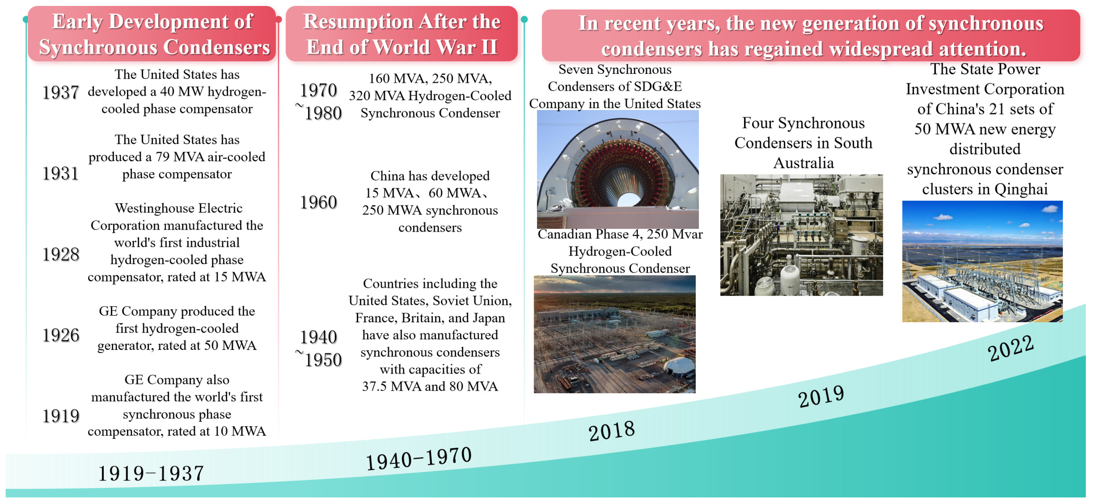
1.1. The Development Process of Traditional DSCs

DSCs, also known as synchronous compensators [4], are essentially a special form of synchronous generators. The internal structure of a synchronous condenser is largely similar to that of a conventional synchronous motor. In contrast, the rotor shaft of a synchronous condenser is relatively slender and does not need to withstand mechanical loads. The operating principle of a synchronous condenser primarily involves regulating the excitation current to control reactive power [5]. Specifically, when operating in under-excitation mode, the synchronous condenser delivers reactive power to the grid; conversely, in over-excitation mode, it absorbs reactive power from the grid. Unlike traditional power electronic reactive compensation devices, DSCs can effectively enhance grid kinetic support through their rotational inertia, providing crucial short-term inertial support to the power system. This characteristic places them in a key position for improving the stability of large-scale power systems.
The development and research of DSCs began in the early 20th century [5], with their earliest widespread application in large power systems in the United States and Europe. Figure 1 outlines the evolutionary process of DSCs. In the 1950s, as the scale of power systems expanded and industrial demands grew, the power density and response speed of condensers gradually improved, making them one of the core equipment for reactive power compensation and voltage regulation in power grids. During this period, technological advancements primarily focused on enhancing the stability and adaptability of DSCs to meet the needs of high-load grid environments. However, traditional condensers were energy-intensive.
By the 1980s, advancements in power electronics led to the development and maturation of static var compensators (SVCs) and static synchronous compensators (STATCOMs). These static reactive power compensation devices, characterized by their small footprint, fast response, and flexible control, rapidly gained popularity in power systems worldwide and to some extent replaced early mechanical condenser units. While static compensators effectively regulate reactive power, they lack the rotational inertia support provided by DSCs.
With the integration of large-scale wind and solar power generation, which has reduced grid system inertia and led to frequency fluctuations, traditional DSCs have regained attention. In the late 20th century, they underwent another round of technological innovation to meet the high demands for system stability in modern grids.
Although modern DSCs excel in reactive power regulation and grid support, their inherent mechanical structures and excitation methods still present certain limitations. Additionally, higher energy consumption and frequent maintenance requirements further constrain their application potential in sustainable power systems. In recent years, SDSCs have gradually become a focal point of research, with the expectation that superconducting properties can enhance the power density and operational efficiency of condensers, reduce energy consumption, and improve transient response capabilities. In this context, the development of SDSCs is not only a complement to traditional technologies but also a significant driver for the transformation of power systems towards higher efficiency and lower carbon emissions.

1.2. Overview of SDSCs

SDSCs replace the traditional copper winding of the rotor excitation in conventional condensers with superconducting coils. In a low-temperature environment, the superconducting magnet composed of superconducting coils can significantly reduce thermal losses, enhancing the overall operational efficiency, power density, reactive power regulation range, and response speed of the condenser, thereby providing superior transient inertia support for the power system.
The core structure of the superconducting synchronous condenser includes a non-magnetic tooth conventional high-voltage stator, a superconducting rotor, a cooling system, and auxiliary control devices, as shown in Figure 2. Compared to traditional condensers, the excitation winding in the rotor of the superconducting condenser uses high-temperature or low-temperature superconducting materials, and is equipped with a cryogenic cooling system to maintain the superconducting state, thereby maximizing its current-carrying capacity and operational efficiency. Additionally, the superconducting condenser employs a non-magnetic tooth stator and high-voltage insulated winding design, effectively reducing iron losses and weight, and enabling direct grid connection without the need for a step-up transformer.
In the structural design, the rotor components of the superconducting phase shifter are encapsulated within a vacuum cylinder chamber. This vacuum chamber not only serves as an electromagnetic shield, blocking magnetic harmonics from the stator, but also enhances the heat dissipation efficiency of the cooling medium to some extent. The superconducting magnet in the rotor is typically excited by an external power source via slip rings and current leads. To both support the superconducting magnet and transmit mechanical torque, two torque tubes made of glass fiber epoxy resin with high strength and low thermal conductivity are installed at both ends of the shaft. The structure of a typical high-temperature superconducting (HTS) dynastic synchronous condenser (DSC) is shown in Figure 3.

1.3. Comparison Between Conventional and Superconducting Condensers

Depending on the application scenarios, traditional DSC, bi-axis excitation DSC, and SDSC each have their own advantages. Conventional DSCs, due to their mature technology and low cost, are widely used in substations and traditional power grids, capable of meeting basic reactive power compensation needs. In regions with a high proportion of renewable energy generation, bi-axis excitation DSCs, as an improved type of equipment, enhance the range of reactive power regulation and response speed by adding bi-axis excitation functionality. As the scale of power grids expands and the proportion of renewable energy increases, the energy efficiency issues and response speed limitations of traditional condensers have become increasingly evident. SDSCs, with their high power density, high system efficiency, rapid response, low energy consumption, and simplified cooling requirements, are particularly suitable for dynamic demand scenarios such as ultra-high voltage transmission and renewable energy grid integration.
Additionally, their low-carbon and environmentally friendly characteristics, along with efficient operation, align with the requirements of sustainable development, making them a forward-looking alternative to traditional condensers. In scenarios involving large-scale renewable energy integration, ultra-high voltage direct current transmission, and smart grid systems, the reactive power compensation capabilities and instantaneous response characteristics of superconducting condensers can significantly enhance grid stability and efficiency, providing a more sustainable technical alternative for modern power systems. The classification and comparison of the advantages of DSC are shown in Table 1. Under the same power density, the volume and mass of HTS motors are only 50% and 33% of those of conventional motors, respectively [12].
Although SDSCs possess significant technical advantages, their promotion still faces challenges such as the complexity of manufacturing technology and cooling system design. In the future, with advancements in superconducting technology, superconducting condensers are expected to be widely adopted in power systems, providing effective support for enhancing grid stability and efficiency.

2. Development Progress of SDSCs

Japan, the United States, the European Union, and several other countries and organizations have conducted in-depth research and development in the field of SDSCs, achieving significant results. The development process is illustrated in Figure 4.

2.1. Research Progress in Europe and America

The global exploration of SDSCs began in the 1970s. Japan made significant progress in the research of SDSCs. In 1977, Mitsubishi Electric Corporation and Fuji Electric Co., Ltd. jointly developed a 30 Mvar low-temperature superconducting (LTS) synchronous dynastic condenser (DSC), which was one of the highest power-rated superconducting machines in the world at that time [17,18]. In 1982, a 20 MVA, 3000 rpm superconducting generator was experimentally operated in the mode of a synchronous condenser in the Russian power grid, with the excitation winding composed of low-temperature superconductors Nb-Ti, demonstrating significant advantages over traditional reactive power compensation. Additionally, the Japanese Super-GM research group began developing a 70 MW superconducting generator based on NbTi LTS materials in 1988. After 12 years of continuous experimentation, the group completed the testing of the superconducting generator in the synchronous condenser mode in 1999. This research achieved important breakthroughs in cryogenic cooling technology and the application of high-power superconducting materials, laying a solid foundation for subsequent research on HTS technology [19]. In 2003, American Superconductor Corporation (AMSC) successfully designed and developed an 8 Mvar, 1800 r/min HTS DSC, which was demonstrated in the Tennessee Valley Authority (TVA) grid in Tennessee [20]. This condenser was the world’s first HTS DSC, and the success of the project not only validated the feasibility of HTS materials in practical power systems but also demonstrated the application value of superconducting condensers in reactive power compensation and grid stability [20,21,22]. The AMSC project incorporated advanced cooling technologies, enabling the superconducting magnet to maintain a low temperature during operation and achieve efficient reactive power regulation, marking a milestone in the application of superconducting motor technology.
European countries have also actively engaged in research related to superconducting phase shifters. The EU-funded BEST PATHS project is dedicated to applying HTS motors in high-voltage transmission systems, with a focus on breakthroughs in the durability of superconducting materials and the miniaturization design of cryogenic cooling systems. Switzerland’s Bruker Corporation has made significant progress in the cooling and material improvements of superconducting motors, while German research teams have achieved advancements in efficient cooling systems and electromagnetic shielding for LTS technology. These projects further promote the potential application of superconducting phase shifters in European power systems.

2.2. Research Progress in China

In contrast, research in the field of superconducting phase shifters in China started relatively later, but has seen rapid development in recent years due to policy support and technological investment. In 2007, under the funding of the National “863” Plan Innovation Project, the 712 Research Institute of China Shipbuilding Industry Corporation (CSIC) successfully developed a 100 kW HTS motor prototype, which first filled the technological gap in the field of HTS motors in China. In 2012, the institute further developed a 1000 kW HTS motor, the largest superconducting motor in terms of single-machine capacity in China at that time, demonstrating advancements in superconducting materials and cooling systems in China [23]. The physical prototypes of the two HTS motors are shown in Figure 5. This laid a theoretical and practical foundation for subsequent research on superconducting phase shifters.
In recent years, Chinese power companies and research institutions have begun to focus on the development and application of superconducting phase shifters. In 2018, China Southern Power Grid Company Limited initiated the development of a 10 Mvar HTS DSC. After continuous experimentation and improvements, the company successfully developed a 300 kvar HTS phase shifter prototype in 2020, which was jointly tested and validated with the State Key Laboratory of Tribology at Tsinghua University [24,25]. In 2024, the Institute of Electrical Engineering, Chinese Academy of Sciences, officially commenced research on a 15 Mvar/35 kV direct-connected HTS DSC without a step-up transformer [26,27]. These research achievements not only enhance China’s innovative capabilities in superconducting technology but also provide new technical options for high-proportion new energy integration and ultra-high voltage transmission systems.
Given the strict confidentiality surrounding the specific structural design and operational data of superconducting synchronous motors, the development of superconducting phase shifters, as a special form of superconducting synchronous motors, has been relatively slow. To conduct a systematic analysis of the system structure of superconducting phase shifters, this paper will focus on three core components: the stator structure, superconducting rotor magnets, and cooling systems [28,29,30], and summarize the key technologies of superconducting phase shifters. Considering that the 15 Mvar HTS phase shifter being developed by the Institute of Electrical Engineering, Chinese Academy of Sciences, lacks publicly available information, it will not be described in detail here. Therefore, the following sections will primarily summarize publicly available information on current engineering practice cases of superconducting phase shifters, including the 30 Mvar LTS DSC jointly developed by Mitsubishi Electric Corporation and Fuji Electric, the 300 kvar superconducting synchronous phase shifter prototype from China Southern Power Grid Company Limited in China, and the 8 Mvar HTS DSC in the United States, in order to provide valuable references and insights for the research and development of superconducting phase shifters.

3. Overall Design and Excitation Winding
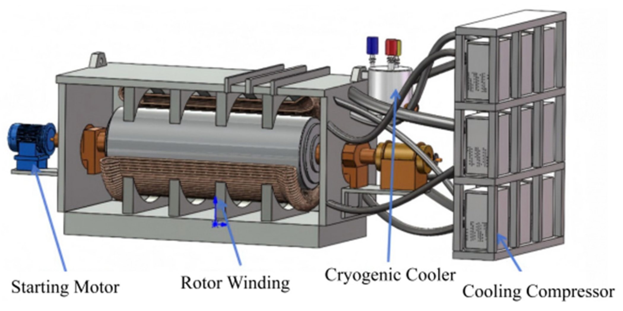
3.1. Overall Design

Table 2 lists the basic parameters of the 300 kVar HTS DSC prototype and the 10 MVA HTS DSC from China, as well as the 8 MVar HTS DSC from the United States and the 30 MVar HTS DSC from Japan.

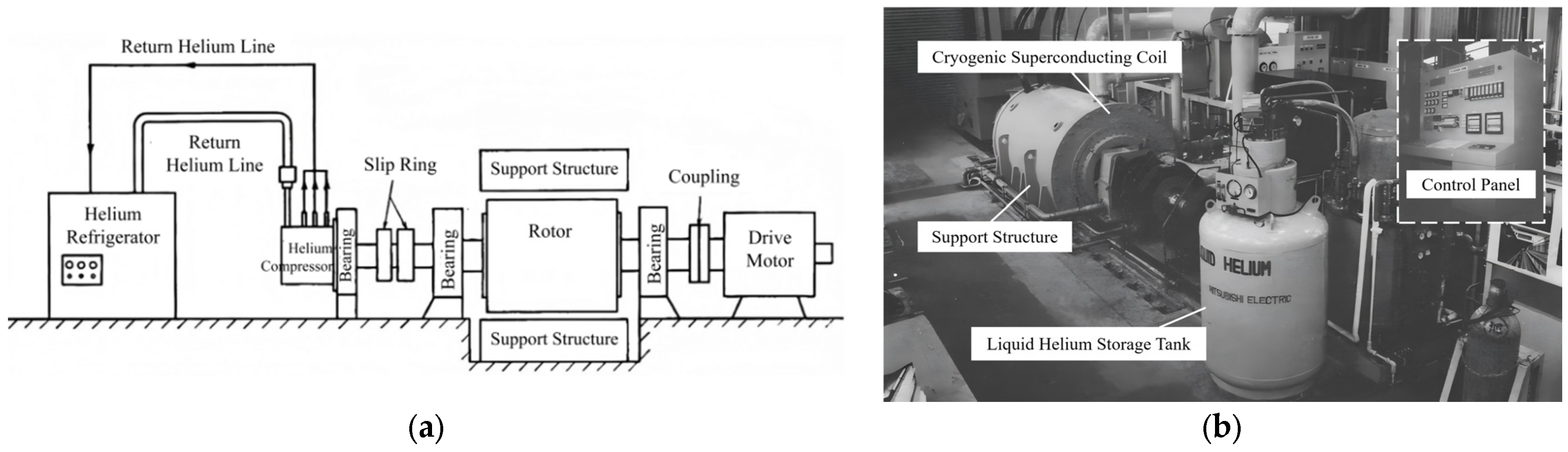
3.1.1. Japan 30 Mvar LTS DSC

The Japanese 30 Mvar LTS DSC has a rated capacity of 30 MVA, an operating voltage of 11 kV, and a rated current of 1575 A, with a power factor of 0 (operating purely in reactive power). The design speed is 3600 rpm with two poles, making it suitable for synchronous compensation needs in high-frequency grids. The coils are embedded in a titanium torque tube and secured with a slot wedge structure to withstand the high centrifugal and electromagnetic forces generated during rotation. The slot wedge fixation method draws from traditional rotating machinery designs, offering excellent mechanical strength and stability. The device integrates sequence control and feedback control systems to manage system startup, shutdown, and liquid helium supply. The feedback control includes regulation of helium pressure, liquid helium level, and vapor pressure to ensure a stable cooling process. The overall structural composition is shown in Figure 6a,b depicting the on-site installation photograph.

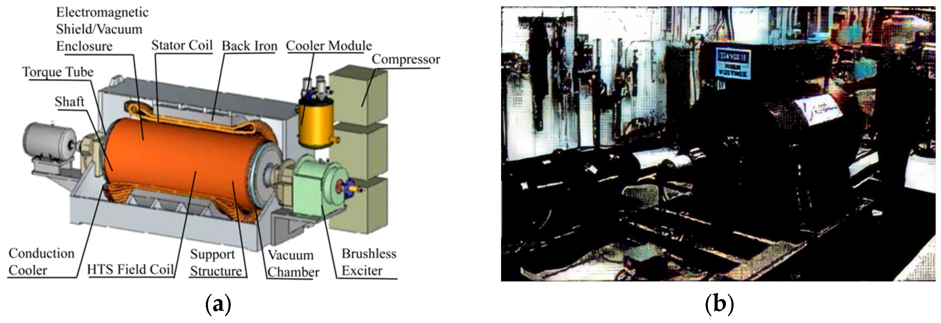
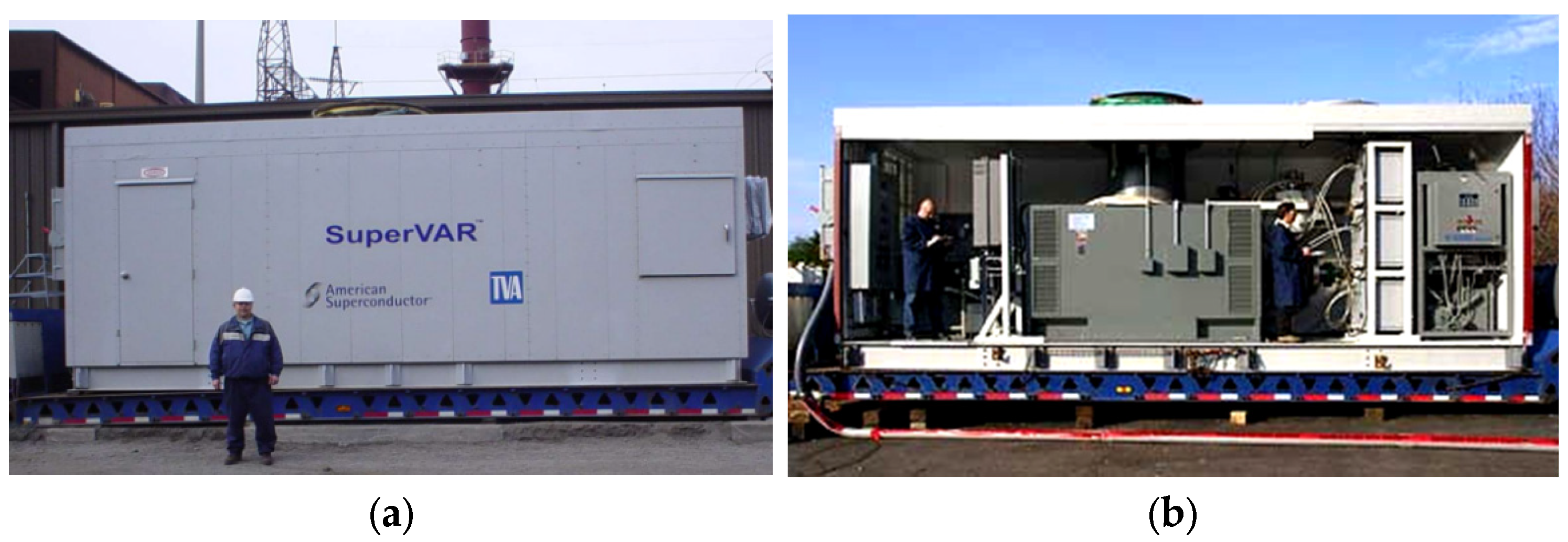
3.1.2. United States AMSC 8 Mvar HTS DSC

The overall structure of the 8 Mvar HTS DSC in the United States consists of key components such as electromagnetic shielding, vacuum housing, HTS coils, support structures, cooling systems, brushless exciter, starting motor, and control systems. The overall structure is illustrated in Figure 7a,b. Among these, the electromagnetic shielding and vacuum housing provide excellent electromagnetic isolation and a cryogenic vacuum environment for the superconducting coils, reducing interference from external magnetic fields and thermal conduction on the superconducting state. A brushless exciter is employed to supply a constant excitation current, avoiding wear and tear associated with traditional brush systems. The control system enables precise monitoring and regulation of the system’s temperature, pressure, and current, ensuring safe operation under various conditions.
The HTS DSC system achieves reactive power compensation and dynamic stability in the power system through the coordinated operation of the aforementioned structure, as illustrated in Figure 8. Initially, a three-phase auxiliary power supply provides foundational electrical support to various modules of the system. Through the monitoring and regulation of the control system, power with different voltages and frequencies is supplied to each subsystem. The control system dynamically adjusts the excitation current to control the magnetic fields of the stator and rotor, enabling the synchronous condenser to precisely provide reactive power and meet the dynamic compensation requirements of the power system. To ensure the superconducting characteristics of the superconducting coils during operation, the cooling system and refrigeration unit utilize helium circulation to maintain the superconducting coils at a low temperature, thereby reducing resistance losses and enhancing the overall efficiency of the system. Additionally, air and oil cooling systems manage the heat dissipation of the stator and rotor to ensure stable operation under high loads.

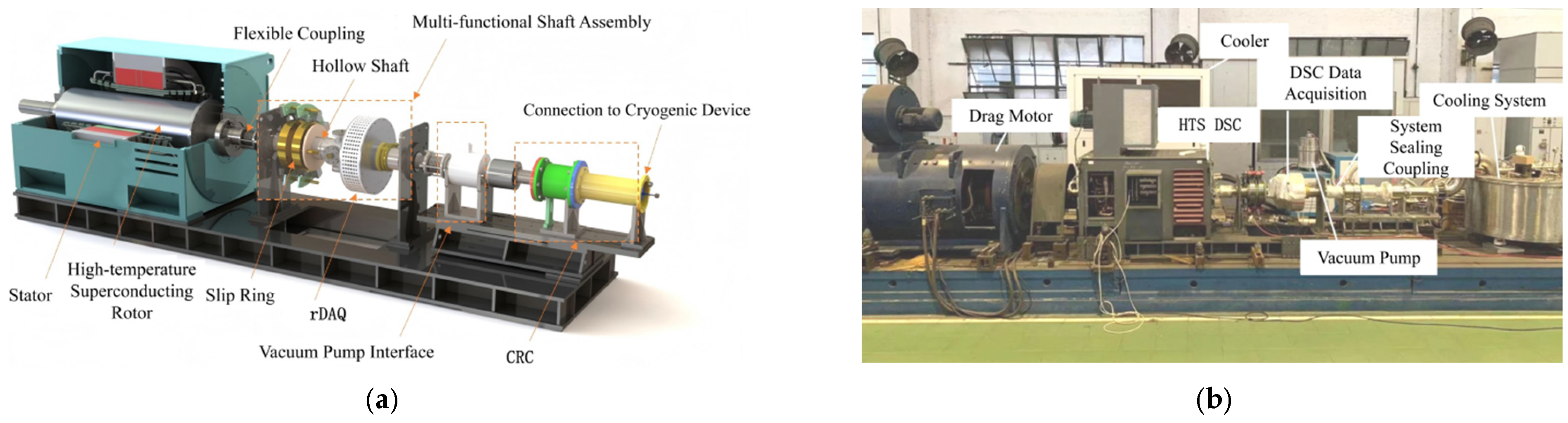
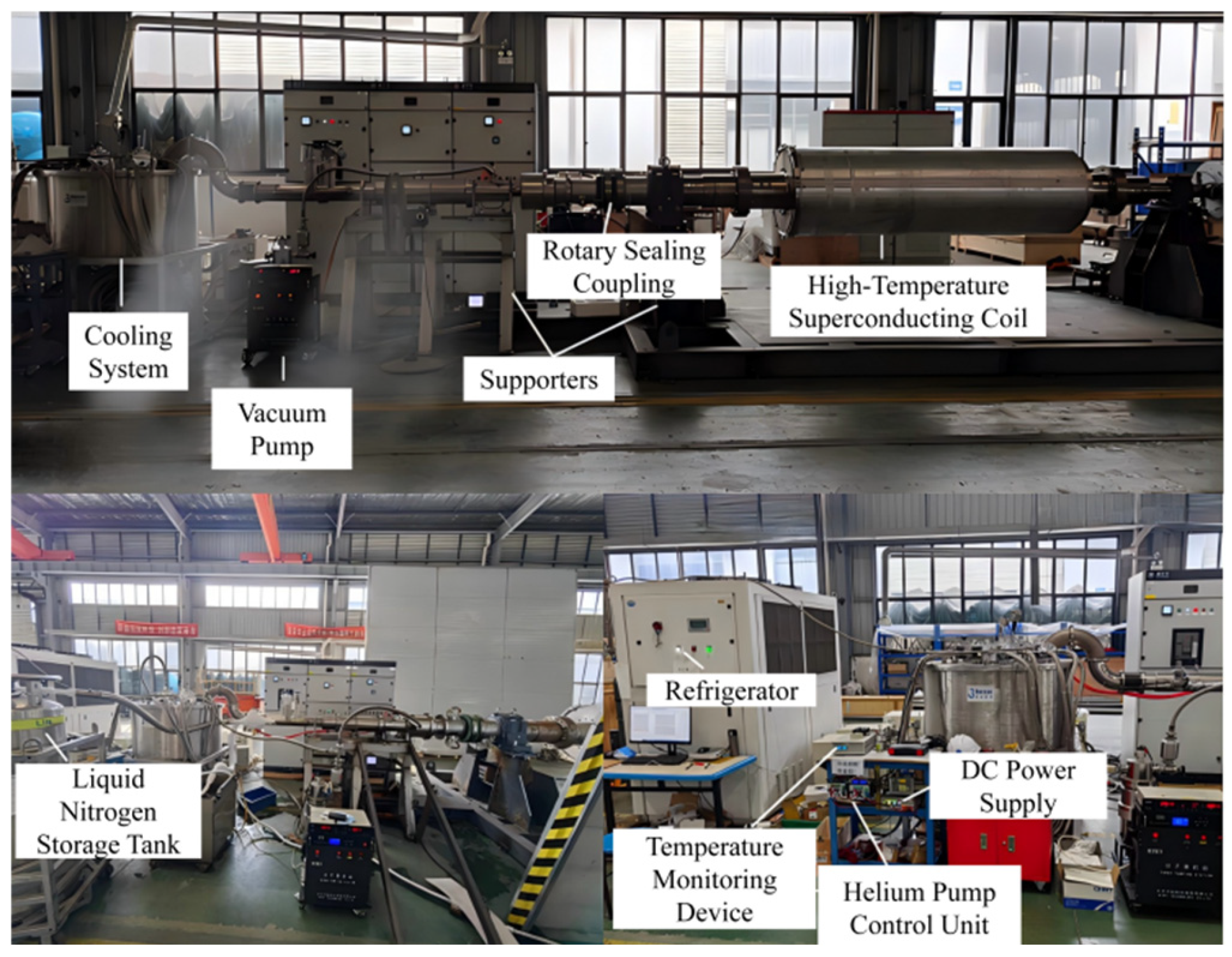
3.1.3. China Southern Power Grid HTS DSC

The 300 kvar HTS DSC prototype developed by China Southern Power Grid Company Limited has a schematic diagram of its overall design shown in Figure 9a. The main structure of the prototype is equipped with multifunctional components, special vacuum pump interfaces, a cryogenic rotary coupling (CRC), and a rotating data acquisition device (rDAQ). The cooling system has been successfully coupled and tested, with corresponding field test images shown in Figure 9b. The data obtained from this test will provide valuable support for the ongoing development of the 10 Mvar HTS DSC by China Southern Power Grid Company Limited. The 10 Mvar HTS DSC is currently undergoing mechanical assembly and commissioning, with the cooling system coupled with the superconducting rotor section. The test setup is illustrated in Figure 10.

3.2. Design and Control Strategy of Excitation Power Supply

The excitation system of superconducting motors can be classified into DC excitation systems, AC excitation systems, and static excitation systems based on the nature of the current output by the excitation power supply. In 2009, Wang Xianqin’s team from the 712 Research Institute of China Shipbuilding Industry Corporation [33] conducted in-depth research on strategies to enhance the air-gap magnetic density of HTS generators. Their research findings indicate that significant improvements in the air-gap magnetic density of superconducting motors can be achieved by carefully selecting superconducting tapes, optimizing the superconducting magnet structure, and assembling ferromagnetic materials on the rotor. Additionally, based on the overall electromagnetic design scheme for superconducting wind turbines proposed by the National 863 Project team, He Jie [34] proposed an optimization design method for superconducting excitation windings using a genetic algorithm in 2015. In 2013, Su Xiaolin [35] utilized optimized genetic algorithms and simulated annealing algorithms to optimize the structural parameters of superconducting excitation windings in HTS synchronous generators, significantly reducing the harmonic amplitudes of the no-load air-gap magnetic density.
To address the issue of unbalanced reactive power output in practical applications of SDSC, Shi Zhengjun et al. [36] proposed a specially designed excitation power supply device for SDSC aimed at suppressing excessive ripple in the excitation current. By optimizing the power supply design, this device effectively enhanced the response stability of the excitation system and reduced the interference of current fluctuations on reactive power output. Xue Manyu [37] took a 10 Mvar HTS DSC as the research object and proposed a new design concept for the excitation power supply system. On a small-scale experimental platform, an equivalent experiment was conducted using a 48.23 mH and 0.15 Ω inductor to replace the superconducting excitation inductor, verifying the operational performance and stability of the excitation system under actual engineering conditions. This provides important references for the engineering application of large-scale SDSC.

4. Stator Structure

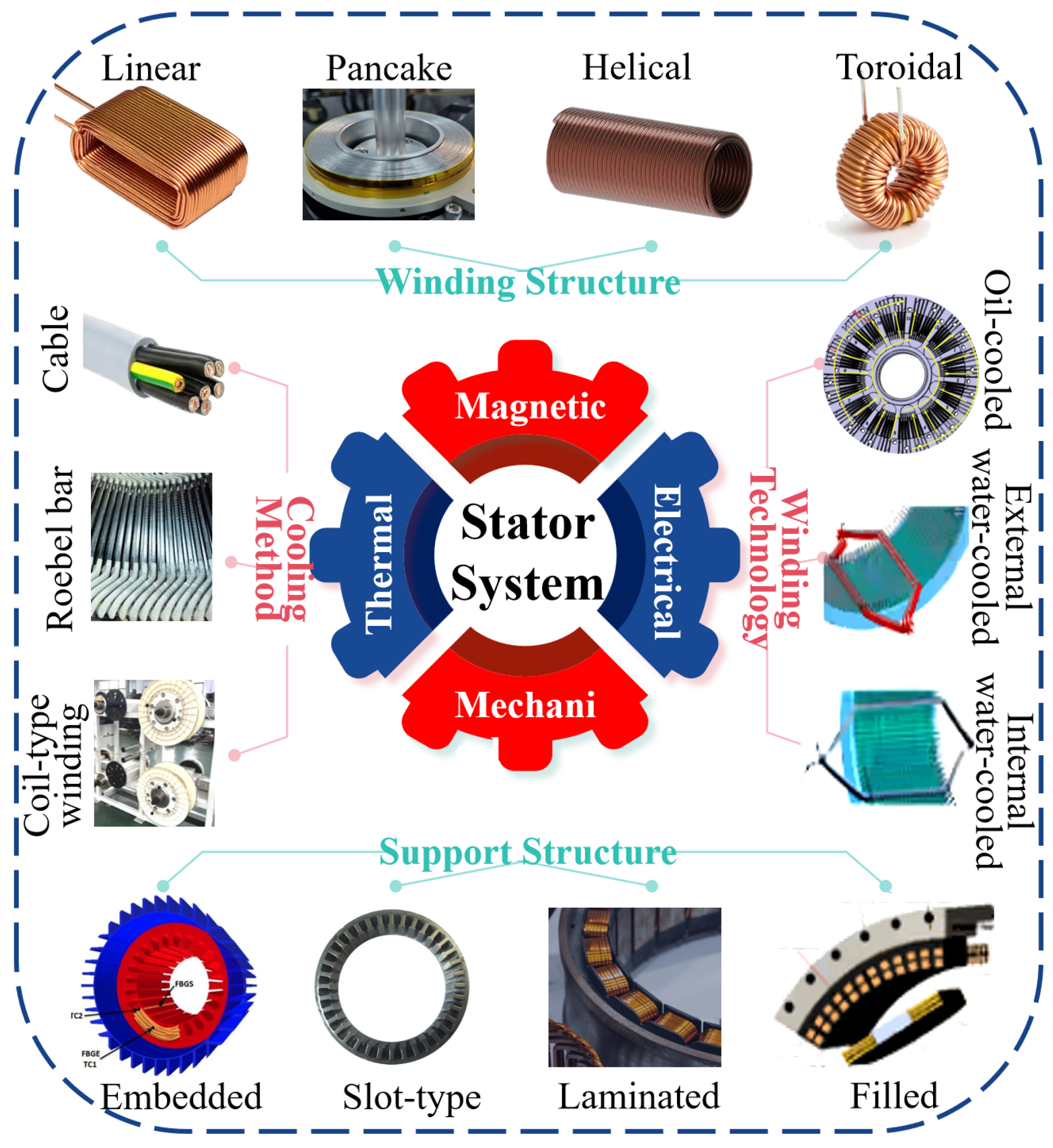
4.1. Overview of the Stator System

The design of the stator system plays a crucial role in the overall performance of SDSC. Figure 11 illustrates the selection of key factors in the design of the stator system, covering the winding structure, cooling method, support structure, and winding technology. The rational combination of these design factors ensures that the superconducting condenser maintains excellent performance under varying grid environments and load conditions. Currently, research on the stator system primarily focuses on the selection of magnetic materials and the enhancement of strong excitation capability to ensure stable electromagnetic performance under high power output conditions.

4.2. Structure of the Stator System

The design of the stator system requires a comprehensive consideration of material durability, electromagnetic performance, and heat dissipation efficiency. Current superconducting phase modulators typically employ a non-magnetic tooth design for the stator structure, optimizing the magnetic field distribution to prevent core magnetic saturation, which would otherwise lead to increased losses and localized overheating. Additionally, various superconducting materials are applied in the stator system to achieve high current density and low loss objectives.

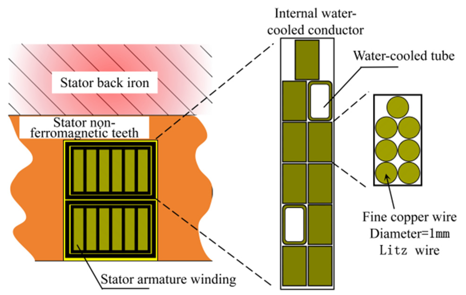
4.2.1. Non-Magnetic Tooth Design

Compared to traditional stator designs, the non-magnetic tooth design can avoid core saturation, reduce hysteresis losses, and enhance the electromagnetic efficiency of the motor. Taking the 10 Mvar HTS phase shifter of China Southern Power Grid as an example, the stator frequency is 50 Hz. The stator is equipped with a water-cooled winding, where the stator teeth and back iron are manufactured using non-metallic materials such as epoxy resin and laminated silicon steel sheets, respectively, to prevent excessive losses and overheating issues due to core saturation. This design effectively controls heat accumulation during full-load operation of the motor, thereby maintaining system stability. The slot configuration of the non-magnetic tooth stator and the cross section of the internal water-cooled conductor are shown in Figure 12.

4.2.2. Dual-Stator Design

The dual-stator design is primarily employed in SDSCs to enhance heat dissipation efficiency and current-carrying capacity. For instance, in 1977, the 30 Mvar LTS DSC developed jointly by Mitsubishi Electric and Fuji Electric adopted a dual-stator design. The dual stator consists of a gap armature with a supporting structure and an iron shielding component. The stator windings, arranged in two layers (i.e., the inner two layers and the outer two layers), are composed of diamond-shaped pancake coils wound in a lap configuration, as shown in Figure 13a. Adjacent coils form a series circuit, while coils on opposite sides form a parallel circuit. The cross-sectional structure of the coils is depicted in Figure 13b, which consists of numerous series-connected coil turns. The inner two layers contain 12 coil turns, while the outer two layers consist of 14 coil turns, each turn being made of twelve rectangular insulated twisted wires with dimensions of 1.4 × 5.0 mm. To reduce energy losses caused by circulating currents, each twisted wire at the transposition ends near two adjacent coils is transposed (rotated 180°). The advantage of the dual-stator design lies in its ability to distribute current loads, alleviating stress on individual stator coils, thereby enhancing the overall system reliability. Additionally, the dual-stator design increases the magnetic flux density, enabling the device to maintain stable output under high-power conditions.
Zhong Houhong’s team [38] proposed a method for estimating the enhanced excitation capability of the superconducting synchronous condenser’s stator winding. By inputting specific computational models and enhanced excitation parameters, and considering the influence of stator cooling water, this method enables automated calculation of the stator’s enhanced excitation capability. This approach helps improve the operational accuracy and stability of SDSCs, particularly in applications with high dynamic requirements, where it demonstrates significant advantages.

5. Rotor Systems

5.1. Overview of Superconducting Rotors

The rotor excitation winding is responsible for providing a stable and adjustable excitation current to the synchronous condenser, forming a magnetic field. It represents the collection of the required excitation current for synchronous generators and the corresponding supporting facilities. In the design of DSC employing superconducting technology, specific superconducting tapes are used to wind the excitation coils. These superconducting tapes exhibit a resistance approaching zero when they reach specific temperature thresholds, magnetic field strengths, and current conditions, thereby enabling the generation of a powerful magnetic field. In the traditional design of the stator−rotor structure of DSCs, copper windings are typically placed inside iron cores to enhance the magnetic field strength. However, the weight of the iron cores accounts for approximately 60% of the total weight of the condenser, and the hysteresis losses generated by them constitute about 80% of the total energy consumption of the condenser. Therefore, traditional DSCs suffer from issues such as excessive mass, high hysteresis losses, and relatively low motor efficiency. By introducing superconducting materials in the design of the excitation winding, the power density of the condenser is improved, significantly reducing its weight and volume. Moreover, this design approach results in a significantly reduced synchronous reactance compared to traditional DSC. Additionally, non-magnetic materials are used in the stator teeth, effectively reducing the noise level of the condenser and increasing the overall working efficiency to over 98% [39]. This innovative design is contrasted with traditional excitation windings and superconducting winding structures, as shown in Figure 14.

5.2. Typical Superconducting Rotor Structure
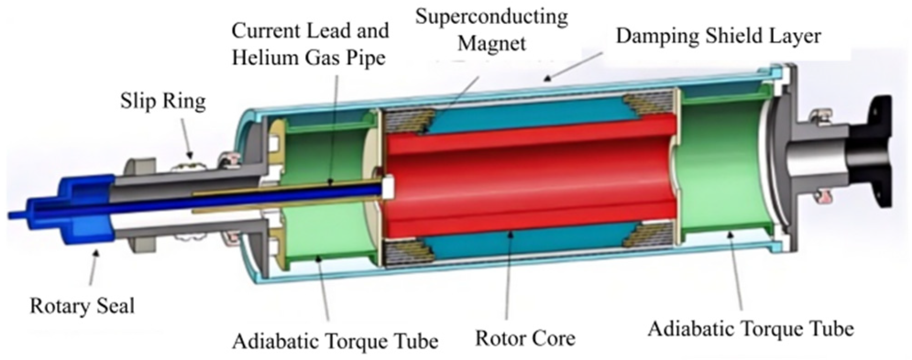
5.2.1. LTS Rotor

In the 30 Mvar LTS DSC jointly developed by Mitsubishi Electric and Fuji Electric in Japan, the design of the rotor involves key components such as adiabatic torque tubes, helium containers, electromagnetic and damping shields, and cryogenic superconducting magnets, as shown in Figure 15. Regarding rotor materials, pure titanium and titanium alloys were selected to meet the performance requirements of different components. The torque tube section is made of Ti-5Al-2.5Sn titanium alloy, the room temperature damper is made of Ti-6Al-4V titanium alloy, and other components of the rotor are made of pure titanium [17].
The rotor is made of titanium alloy (Ti-5Al-2.5Sn), which exhibits excellent low-temperature mechanical properties and a low coefficient of thermal expansion, meeting the strength requirements of the superconducting rotor. A physical image is shown in Figure 16. The central part of the rotor is designed with a “helium groove” structure with a diameter of 280 mm, used for liquid helium storage and low-temperature heat dissipation. Liquid helium is directly filled into the rotor groove, maintaining the superconducting coil at an operating temperature of 4.5 K to ensure its superconducting state. In the rotor structure, a vacuum insulation layer and a radiation shield are provided, and an external copper cryogenic damper (thickness 8 mm, outer diameter 634 mm, length 1980 mm) is installed to reduce heat transfer. Additionally, the lateral thermal shield layer is made of pure titanium discs with a thickness of 10 mm, which are cooled by helium to further reduce thermal intrusion.

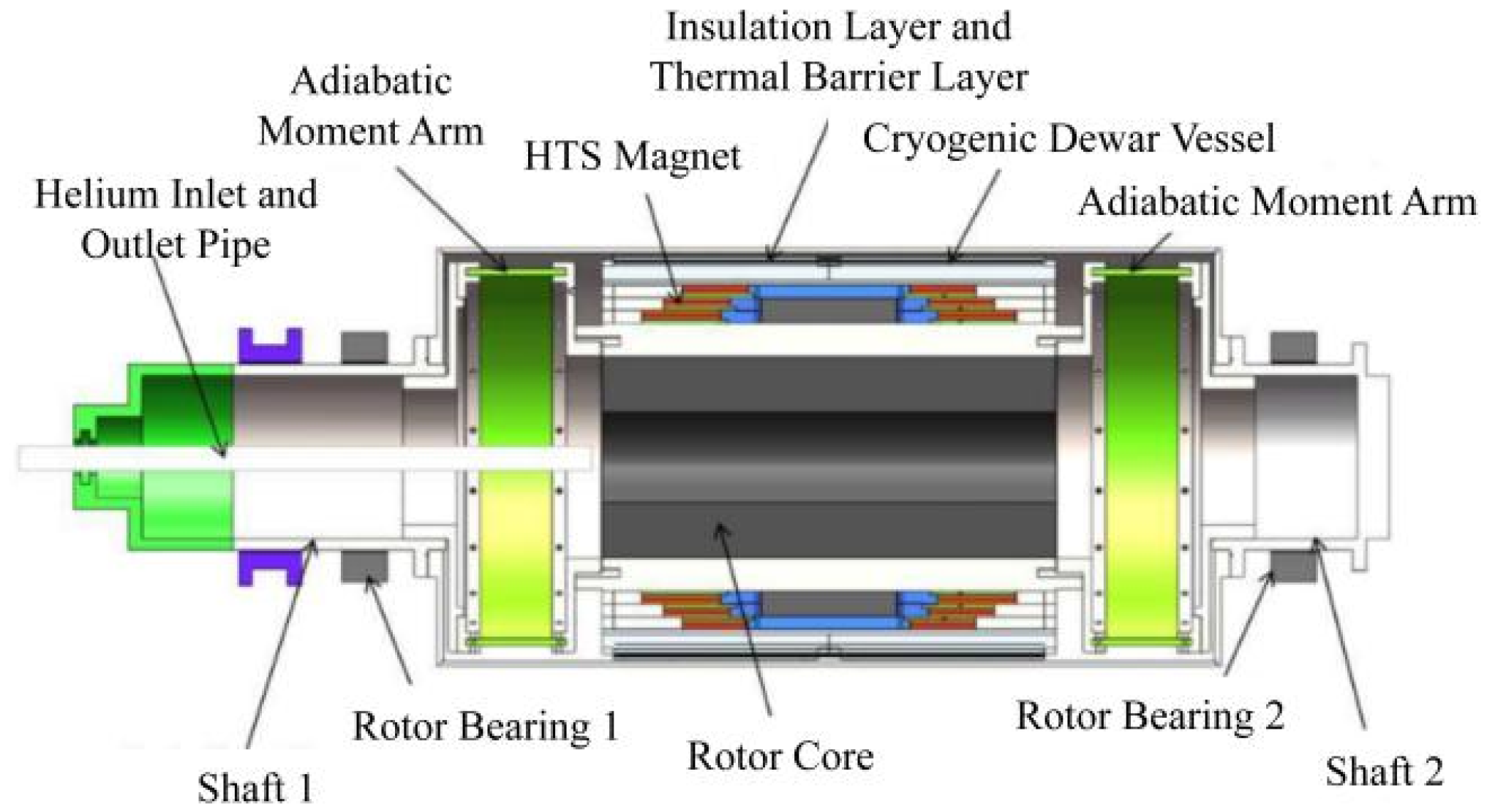
5.2.2. REBCO-Based HTS Rotor

The rotor of the 300 kvar HTS DSC prototype developed by China Southern Power Grid Company Limited consists of two REBCO (Rare Earth Barium Copper Oxide) coil assemblies, each containing four double-pancake-shaped REBCO coils of different sizes. The rotor cross section is shown in Figure 17. These coils are conduction-cooled through helium channels embedded within them. The main frame of the rotor is made of stainless steel 316L to prevent cold brittleness during rapid excitation and unexpected eddy current losses. The REBCO coils are mounted on the main frame and secured using six stainless steel 316L reinforcing rings. To transmit electromagnetic torque from the cryogenic REBCO coils to the room-temperature shaft while minimizing conductive heat leakage, two thin-walled cylindrical torque tubes made of G-10 glass fiber reinforced epoxy resin (GFRP) are used to support the cryogenic main frame. Between the reinforcing rings and dampers, multi-layer thermal insulation (MLI) is wrapped around the inner rotor to reduce radiation and residual gas conduction. Additionally, to ensure the thermal stability of the REBCO coils, two spiral heat exchangers are tightly installed at the cold end of the torque tubes, in addition to the cooling channels inside the coils, to absorb heat leakage from the torque tubes and current leads. The rotor structure of the 10 MVA HTS phase modifier is based on the 300 kvar prototype, and its sectional structure schematic is shown in Figure 18.

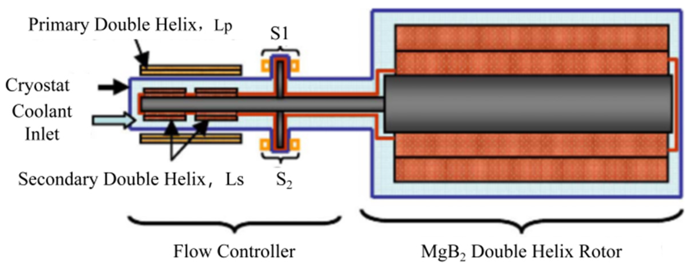
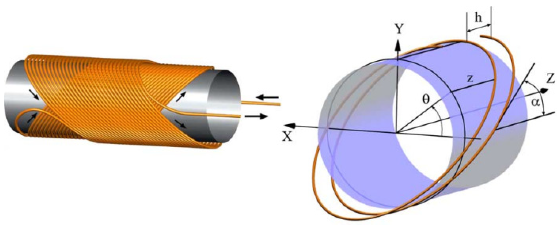
5.2.3. MgB2-Based Double-Helix Rotor

Sasha Ishmael et al. [40] proposed a rotor structure based on an 8 MVA, 3600 rpm, 2-pole superconducting motor, and synchronous condenser, utilizing MgB2 windings operating in a constant current mode. The arrangement of the flux pump and rotor coils is illustrated in Figure 19. The flux pump transformer (FPT) consists of a copper primary winding and two superconducting MgB2 secondary windings housed within a cryostat. The density of MgB2 is approximately half that of BSCOO and YBCO, which helps reduce the power-to-mass ratio of all coils. The aperture of the primary winding encompasses the extension of the rotor shaft around which the FPT secondary coils are wound. The HTS flux pump, made of MgB2, connects the secondary flux pump coils with the machine’s rotor in a persistent current loop.
Both the secondary FPT coils and the rotor are double-helix multilayer dipole coils. The double-helix excitation winding can withstand large Lorentz forces due to its self-stabilizing, solenoid winding configuration. The larger bending radius of the double-helix winding facilitates the winding of fragile HTS materials, simplifying the manufacturing process. This design approach allows for high rotor currents of several kA, which helps reduce rotor inductance and simplifies the quenching protection of the machine, as the hotspot temperature and peak voltage of the superconductor increase with inductance. The geometry is shown in Figure 20.

5.3. Typical Superconducting Rotor Magnet

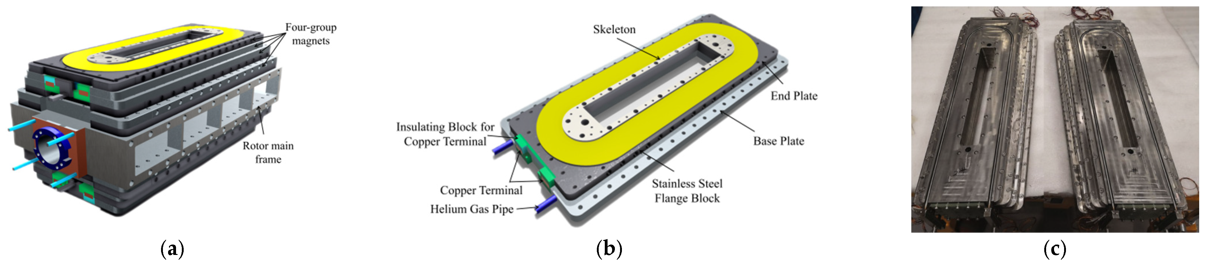
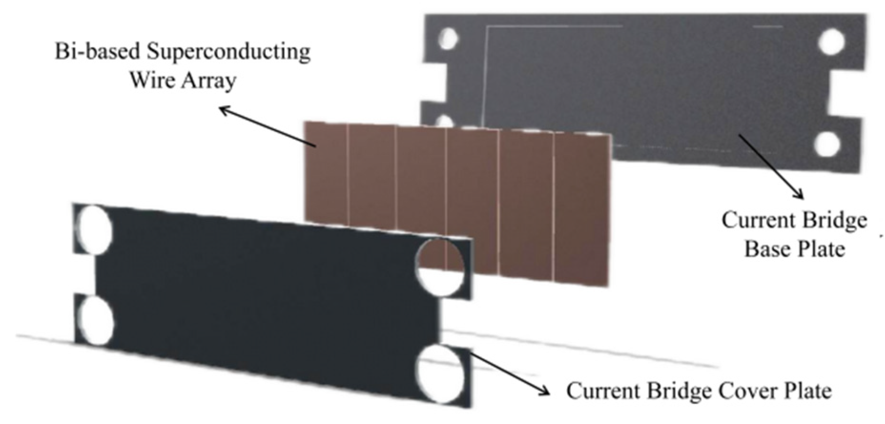
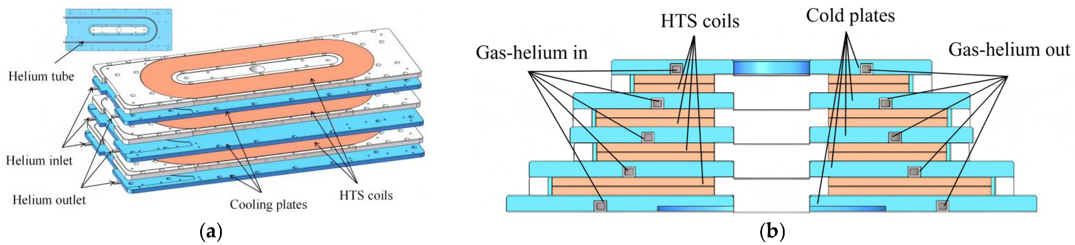
5.3.1. Pole Racetrack-Shaped Double-Pancake HTS Coils

The superconducting rotor magnet structure of the 300 kvar HTS DSC prototype machine of China Southern Power Grid, as described in reference [41], is shown in Figure 21a. The rotor magnet employs a two-pole structure, consisting of two sets of HTS magnets, with each set comprising four stacked racetrack-shaped double-pancake HTS coils. The prototype machine operates at a rated speed of 3000 r/min, with a normal working frequency ranging from 20 to 40 Hz. The rotor magnet is wound using REBCO HTS tapes, designed to operate at a temperature of 30 K, and is cooled via conductive cooling with cold helium gas, with the actual operating temperature maintained between 25 and 30 K. Excitation is achieved through current leads connected to slip rings.
Figure 21b illustrates the structure of the double-pancake coils that constitute the rotor magnet, each equipped with independent copper terminals, allowing for individual performance testing after the completion of a single coil. Embedded within the base plate are cryogenic helium gas circulation pipelines, and the rotor interior is maintained under vacuum to facilitate rapid overall cooling of the superconducting magnet by the cryogenic helium gas circulation [41]. To ensure magnet safety, the upper limit of the operating current is set at 333 A under a 0.9 operating factor at 30 K. When the operating current is 220 A, the operating factor of the rotor magnet is approximately 0.48. In a liquid nitrogen environment, the superconducting rotor magnet can safely conduct a current of 50 A. The current-carrying experiment results indicate that the resistance values of all joints inside the superconducting rotor magnet are less than [specific value], demonstrating excellent electrical conductivity and structural stability. The technical parameters of the 300 kvar HTS DSC and 10 Mvar are shown in Table 3.
To reduce the joint resistance of superconducting magnets, an enhanced superconducting current bridge joint structure was employed, as illustrated in Figure 22. The dominant conductor of the superconducting current bridge consists of a Bismuth Strontium Calcium Copper Oxygen (BSCCO) HTS tape array. Additionally, copper-made current bridge base and cover plates were designed to provide mechanical protection, with the entire assembly being sealed using tin soldering [41,42].

5.3.2. Winding-Reaction Method for LTS Magnet Coils

The superconducting field coils are constructed using NbTi and Nb3Sn superconducting materials, designed as eight coils in total, with two being Nb3Sn coils and the remaining six being NbTi coils. The Nb3Sn coils undergo a heat treatment process after winding—manufactured using the “Wind and React” method—to enhance mechanical strength and current-carrying capacity. Insulation is achieved through the helical winding of insulating tape, and the coils are directly cooled using liquid helium. During performance testing, the Nb3Sn coils were rated for an operating current of 770 A and withstood currents as high as 1007 A without degradation in rotary tests. The dimensions of the Nb3Sn coils are 0.66 m in length and 0.15 m in width, with an inductance of 13 mH, as shown in Figure 23. The NbTi conductors are also insulated using helical winding of insulating tape and directly cooled with liquid helium. Tests in liquid helium showed that the quench current of the NbTi coils is approximately 1000 A, which is 80% of the short sample critical current (Ic), sufficient to meet the requirement of their 770 A rated operating current. The NbTi coils have larger dimensions, measuring 1.322 m in length and 0.618 m in width, with an inductance of 1.94 H. The process parameters for Nb3Sn and NbTi are listed in Table 4.

5.3.3. Two Sets of HTS Magnets

The researchers at the Institute of Electrical Engineering, Chinese Academy of Sciences, pointed out in [26,27] that the combination of four magnetic pole windings forms a HTS magnet. The rotor cross section is shown in Figure 24. To ensure that the rotor windings remain below 30 K, the HTS magnet needs to be placed inside a cryostat, which is wrapped with multiple layers of insulation film. The cross section of this rotor structure is illustrated in Figure 2. Due to the rotor operating at a speed of 1500 rpm, the cryogenic windings inside the rotor must be connected to the 300 K cryostat in a stable manner. This connection must both limit heat conduction and support large torque transmission. Research has found that epoxy glass fiber, with an average thermal conductivity of 0.35 W/mK and a tensile strength limit of 53 kg/mm2, was selected as the primary torque transmission material.
The magnetic coil of the superconducting phase modulator consists of multiple racetrack-shaped double-pancake coils, which are stacked together in different numbers to form the magnetic pole, as shown in Figure 25a. Each magnetic pole contains four racetrack-shaped double-pancake coils, wound using 4.8 mm wide and 0.45 mm thick REBCO tapes, and encapsulated with a 75 μm copper layer and a 50 μm Kapton film to enhance mechanical strength and interlayer insulation. The coils are wound around a skeleton, fixed on a substrate, and secured by coil clamps, with cooling pipes installed around them for cooling. A physical image of the racetrack-shaped double-pancake coils wrapped and assembled with fastening tools is shown in Figure 25b.

5.4. Material Selection

The superconducting materials primarily used in the rotor magnets of SDSC include high-temperature superconductors such as REBCO and BSCCO, as well as low-temperature superconductors like Nb3Sn and NbTi. These materials, known for their mature and stable properties, have found relatively widespread applications in superconducting motors. The selection of superconducting materials should further balance cost and performance to enhance the feasibility of their application in large-scale power grids.
The superconducting rotor magnet of the 300 kvar HTS DSC prototype developed by the Southern Power Grid employs REBCO-coated conductors as the HTS tape for winding. The REBCO-coated conductor material possesses an exceptionally high critical current density, capable of operating within a relatively high-temperature range (30 K–77 K), and exhibits strong thermal stability, making it highly suitable for application in power grids with significant dynamic variations [43,44]. To enhance the current performance of the superconducting excitation winding under low temperature and high magnetic field conditions, C-276 Hastelloy is selected as the substrate for the REBCO-coated conductor, while the superconducting layer utilizes either “EuBCO + BaHfO3” or “YGdBCO” as the superconducting material [45]. The high mechanical strength and thermal resistance of these materials enable them to maintain stable output even under high dynamic loads.
The 30 Mvar cryogenic superconducting phase-shifting machine rotor magnet in Japan employs Nb3Sn material [46,47], renowned for its high mechanical strength and magnetic fatigue resistance, making it suitable for stable operation in extremely low-temperature environments (4.2 K–20 K). The material’s high magnetic conductivity and durability make it excel in scenarios requiring high stability in cryogenic, high-power grid applications. However, its drawbacks include higher costs for the cooling system and stringent requirements for maintaining low temperatures. The 8 Mvar HTS phase-shifting machine rotor magnet in the United States utilizes BSCCO material, a composite HTS material with high current density and low loss characteristics, suitable for medium to high-temperature ranges (20 K–50 K). Despite its greater brittleness, advancements in packaging technology have effectively enhanced the material’s durability, allowing it to maintain excellent electromagnetic performance under both low temperatures and high loads, providing technical support for reactive power compensation in high-frequency environments.

6. Cooling System

6.1. Overview of the Cooling System and Selection of Technical Solutions

The cooling system is the core guarantee for the stable operation of SDSC, especially in low-temperature environments, where the efficiency and stability of cooling technology determine the performance of superconducting materials. The system typically consists of key components such as a cryogenic system, a refrigeration system, and insulated torque tubes. The superconducting rotor magnet of HTS DSC generally operates at a temperature of around 20 K, which requires it to be housed in a cryogenic vacuum vessel to maintain a stable working condition. During the operation of the superconducting rotor, various heat loads are generated, including heat leakage and energy losses from the superconducting magnet itself, heat leakage caused by radiation or thermal conduction from the cooling system, and heat leakage and energy losses from the conductive wires [42]. Effective methods are needed to remove these heat loads from the cryogenic system. Currently, a widely used approach is to construct a refrigeration system based on the principle of regenerative refrigeration cycles to provide a stable low-temperature environment for the superconducting magnet [48]. Common cooling methods for superconducting magnets are shown in Table 5.
To ensure that the heat generated during the operation of superconducting magnets and other components is promptly dissipated, researchers, both domestically and internationally, have explored various cooling solutions. In engineering practice, rotational thermal management technology [49] and cold helium gas circulation cooling technology [56] are among the more commonly used cooling schemes. Dai Yijun et al. [55] conducted an in-depth analysis of the rotor cooling process in a 300 kW HTS motor rotor using the lumped parameter method based on a closed helium gas circulation cooling system. This successful effort reduced the rotor system temperature to approximately 25 K, achieving a significant technical breakthrough. Additionally, in response to the operating temperature design specifications for the superconducting magnet of the 10 Mvar HTS DSC in the Southern Power Grid, Shi Zhengjun et al. [57] designed a cryogenic thermal management system using circulating cold helium gas in a vacuum environment. This system was coupled with a 300 kvar HTS DSC prototype for testing. The test results indicated that the cryogenic thermal management system could stabilize the rotor temperature at 22.4 K, validating its effectiveness and stability in practical engineering applications. The team led by Wang Lei at the Institute of Electrical Engineering, Chinese Academy of Sciences [58], designed a cryogenic test fixture for a HTS phase shifter. This device allows for cryogenic testing of the racetrack-shaped HTS coils used in the phase shifter’s rotor magnet under various temperature conditions. This ensures that the superconducting phase shifter maintains its cryogenic performance across diverse operating environments, providing support for a wide range of application scenarios.

6.2. Innovation and Application of Efficient Cooling Technologies

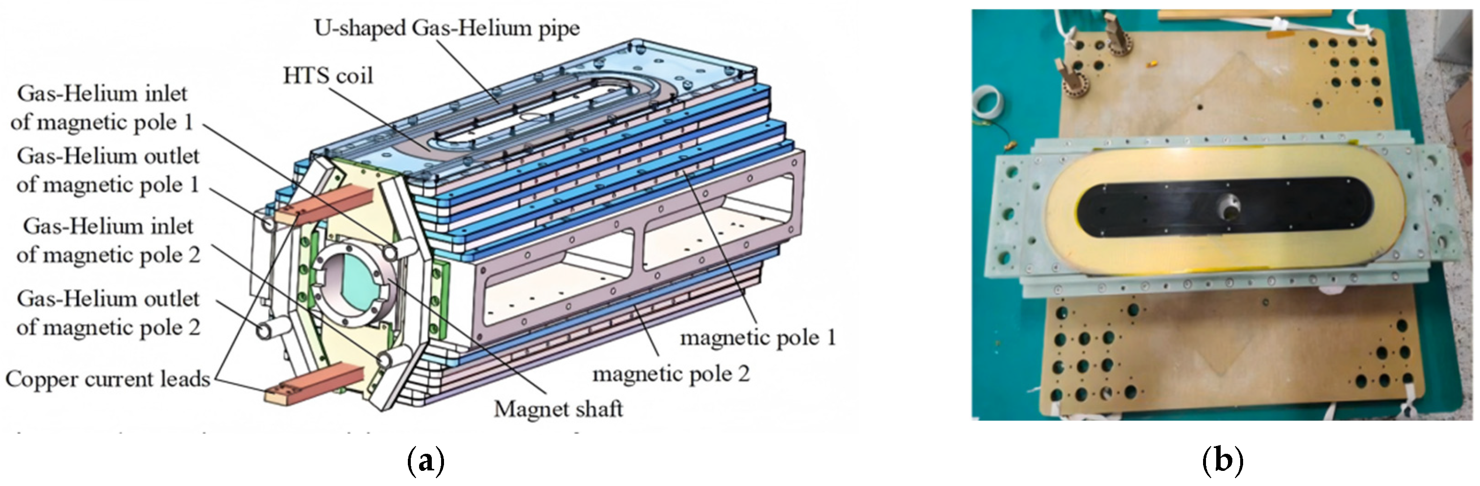
6.2.1. Helium Liquefaction Cooling

The cooling system of the 30 Mvar superconducting synchronous condenser developed through collaboration between Mitsubishi Electric and Fuji Electric includes core components such as the liquid helium circulation system, gas purification device, cryocooler, and compressor, as shown in Figure 26. In a cryogenic environment, the buffer pad employs a composite cylindrical structure made of copper and pure titanium, where the copper cylinder, serving as the inner structure of the conductive component, has an outer diameter of 604 mm, a length of 1951 mm, and a thickness of 8 mm. The pure titanium cylinder, applied to the outer side of the conductive component base, has an outer diameter of 634 mm, a length of 1980 mm, and a thickness of 15 mm. Additionally, all operating units and equipment are integrated into an integrated control panel, enabling remote monitoring of the entire cooling system.
The system employs a 30 L/h helium liquefier, which achieves liquefaction through a Claude cycle helium liquefier machine with a rated liquefaction capacity of 30 L/h, and uses liquid nitrogen (LN2) for precooling at the front stage. The liquefaction system includes four dry gas reciprocating expanders, seven aluminum plate-fin heat exchangers, and one spiral coaxial Joule−Thomson heat exchanger. The system is divided into two different temperature levels, each equipped with two expanders. This configuration ensures that the system maintains low temperatures while achieving high liquefaction efficiency. The compressor selected is an oil-free swash plate type, with a helium flow rate of 16 g/s and an operating pressure of 1.6 MPa. Additionally, the system is equipped with a 400 L liquid helium storage Dewar for storing and managing liquid helium. To maintain high GHe (gaseous helium) purity, the system includes a two-stage adsorption purification device, with one stage operating at room temperature and the other immersed in liquid nitrogen, ensuring that the helium remains at an extremely high purity during the cooling process. The GHe purity control includes a dew point below −80 °C and an oxygen concentration controlled to within 0.1 ppm.

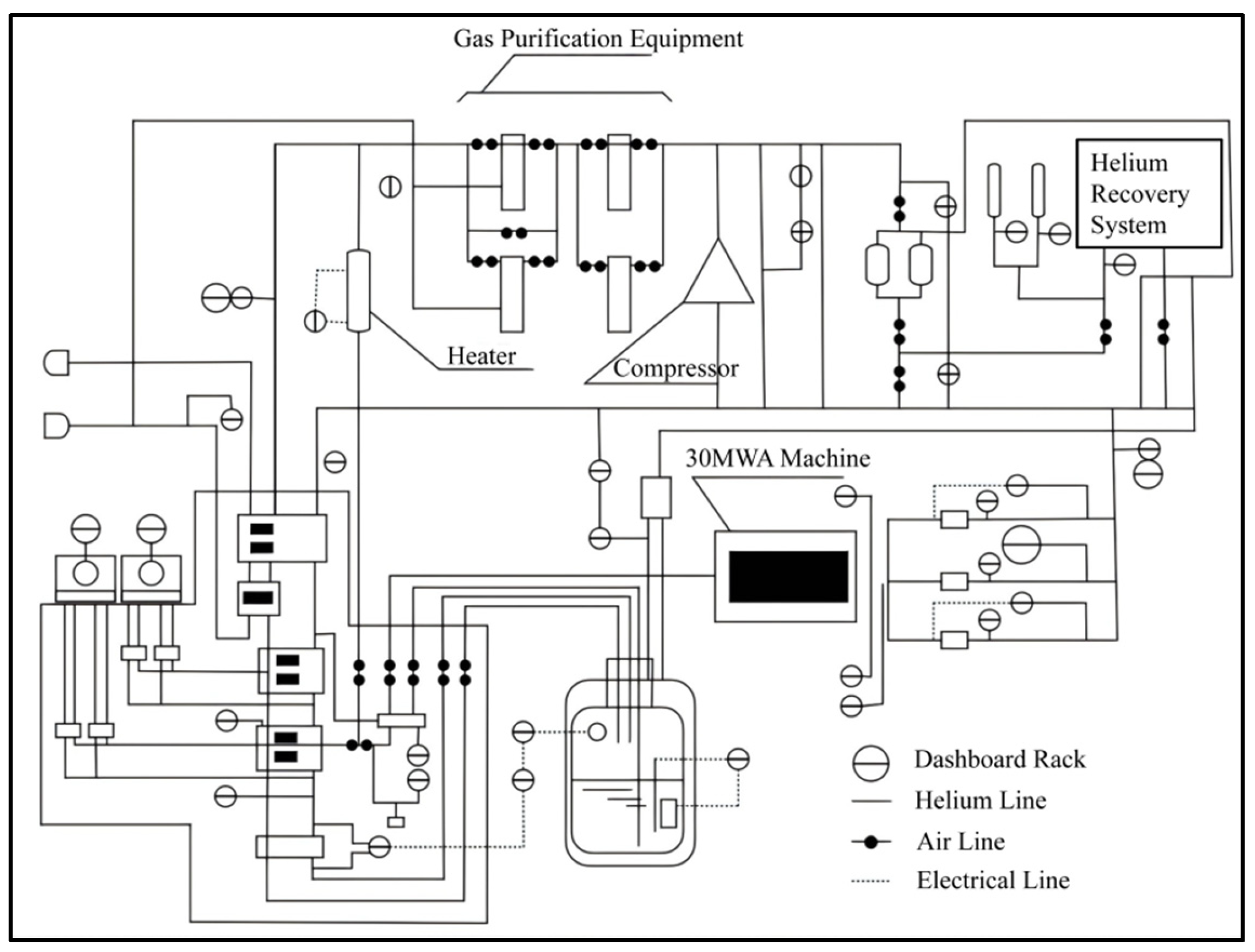
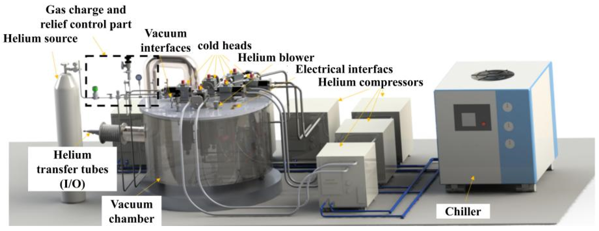
6.2.2. Cryogenic Helium Circulation Cooling System

The refrigeration equipment for the 8 Mvar HTS DSC manufactured by American Superconductor Corporation is shown in Figure 27. Here, the superconducting rotor magnet is independently cooled using a cryocooler subsystem [60,61], maintaining the magnet’s operating temperature between 35 and 40 K. This cryocooler module is installed within a stationary frame and utilizes injected gaseous helium or liquid neon as the cooling medium [20]. In contrast, the stator windings are designed with traditional copper windings. The entire cooling system employs a Gifford−McMahon (GM) cooler, capable of cooling the HTS magnet to 30 K.
China Southern Power Grid Company Limited has developed a cryogenic thermal management system using circulating cold helium gas as the medium [62]. Figure 28 illustrates the composition of the 10MVAHTS DSC cooling system, which is primarily divided into four main parts: the cooler [63], the cryogenic helium pump [64], the delivery pipeline [65], and the charging and discharging pipeline [66]. Three cryogenic coolers serve as the cold source, providing a cooling capacity of over 120 W at 20 K. The primary function of the cryogenic helium pump is to overcome the pressure drop of approximately 2.5 kPa generated by the circulating helium gas within the delivery pipeline and heat exchanger [67,68]. During static testing, the superconducting magnet was able to cool to about 26.2 K within five days [69]. Figure 28 shows the rotor cooling system of the 300 kvar HTS DSC prototype. In Figure 29, A represents three sets of SRDK-500B refrigerator heads and heat exchanger combinations, B is the helium storage tank, C is the cryogenic rotary coupling, D is the copper heat exchange disk, E is the HTS rotor, F is the DE heat exchanger, and DT-470 is a silicon crystal diode.
The Institute of Electrical Engineering, Chinese Academy of Sciences, pointed out in reference [27] that the operating temperature requirement for the internal winding of the phase shifter rotor is <30 K, with 20 K cold helium as the refrigerant. The condenser rotor has an outer diameter of <1000 mm. The design of the 15 MVAR HTS DSC rotor needs to meet all the above parameters. Cooling plates are placed between each winding layer to ensure uniform cooling of the windings. Helium pipes are arranged inside the cooling plates, through which helium flows to cool the windings before returning to the external cooling system. The helium cooling pipes are shown in Figure 30. To reduce thermal leakage, low thermal conductivity and high-strength insulating materials, such as epoxy fiberglass and insulating films, were chosen for the connection between the internal windings and the external casing. Simulation analysis results show that under a certain thermal load, the maximum temperature of the windings is 25.8 K, meeting the cryogenic environment required for superconducting coils.

7. Practical Application Cases

In October 2004, the world’s first HTS DSC was successfully installed in the TVA power grid. This grid primarily serves electric arc furnaces, which exhibit significant transient reactive power consumption during operation, providing an excellent testbed for reactive power compensation [20,70]. The basic technical parameters of the 8 Mvar HTS DSC in the United States are shown in Table 6. Based on the successful operation of the first HTS DSC, TVA further ordered five HTS DSCs with a rated capacity of 12 Mvar, marking HTS DSC as the first HTS commercial product capable of enhancing grid stability.
Figure 31a,b depict the overall appearance and internal structure of the 8 Mvar HTS DSC in the United States. The test results indicate that this 8 Mvar HTS DSC exhibits the following advantages:
(1)
When the motor operates at rated power, its transient dynamic voltage support and stability performance (including leading and lagging VARS) are excellent, making it suitable for various voltage regulation and power quality issues related to reactive compensation;
(2)
Compared to traditional DSC, this synchronous condenser significantly reduces operating costs, especially under partial load conditions, where motor losses are minimal. Additionally, the elimination of thermal cycling avoids the costs associated with rotor rewinding;
(3)
The harmonic levels generated by the condenser are extremely low, eliminating the need for additional filters;
(4)
The installation process is straightforward, as it is a pre-packaged, independent modular unit;
(5)
It can operate normally on the low-voltage side of transmission and distribution transformers, with a stator suitable for distribution-level voltages not exceeding 13.8 kV. In most applications, no additional step-up transformers are required.
However, in practical engineering, TVA and AMSC have jointly decided to terminate the order for five 12 Mvar high-temperature SDSCs, and AMSC subsequently suspended the development of its SuperVAR synchronous condenser product [71]. A major reason for this is the rise in the price of superconducting materials, which has made the technology less competitive compared to power electronic systems capable of providing the same reactive power compensation. Market demand is primarily focused on larger-capacity reactive power compensation equipment, which necessitates the development and testing of new, higher-capacity HTS DSCs. As the cost of HTS tapes and cryogenic cooling decreases, along with the optimization of manufacturing processes, HTS DSCs are likely to remain commercially viable products in the future.
The research on superconducting phase shifters dates back to the 1970s and has accumulated several decades of history. The current mainstream focus of research and application is primarily on HTS phase shifters. From the perspective of stability, the operating temperature of LTS materials in superconducting phase shifters is around 4 K, which is less than 6 K away from their critical temperature. As a result, they are prone to quenching when subjected to thermal disturbances. In contrast, HTS magnets in superconducting phase shifters operate at approximately 30 K, while the critical temperature of HTS materials is 77 K, providing a higher temperature margin. This makes HTS phase shifters significantly more stable than their low-temperature counterparts. For ultra-high voltage direct current (UHVDC) transmission systems and large direct-drive wind turbines, operational stability is a critical consideration. With the continuous advancement of superconducting power technologies and the gradual expansion of HTS materials in the market, it is expected that the cost of HTS materials will gradually decrease, making HTS phase shifters a crucial technological reserve.

8. Current Technical Challenges and Future Prospects

8.1. Electromagnetic Design and Manufacturing Process

Compared to conventional DSCs of the same capacity, SDSCs exhibit greater short-circuit capacity, higher power density, and operational efficiency. However, the internal flow field and heat transfer model of the HTS rotor magnet, as well as the distribution pattern of the transient temperature field at high rotational speeds, are highly complex. Additionally, the insulation theory foundation for non-magnetic, high-voltage direct-connected stator windings has not yet been established. Furthermore, most superconducting synchronous machines in operation domestically and internationally currently adopt a separate design approach, with the superconducting rotor and conventional stator being designed independently. This has led to vague and relatively isolated integrated design theories, resulting in a rough design process. Moreover, under grid-connected operating conditions, the transient mechanism of high-voltage direct-connected superconducting synchronous machines remains unclear. In the following research, the computational fluid dynamics (CFD) method combined with finite element analysis (FEA) can be considered to simulate and optimize the heat flow distribution and transient temperature field of the superconducting rotor. For example, a multi-physics coupling model is developed to simulate the heat transfer path of SDSC at high speed to optimize the cooling channel design.
The electromagnetic, structural, and thermal management systems of superconducting condensers are severely interdependent, necessitating a clear understanding of the coupling relationships and mutual constraints among multi-physics field parameters. Secondly, the excellent strong excitation capability and overload capacity of superconducting condensers rely on the reasonable design of transient performance parameters. Currently, there is no design method for transient performance parameters specifically tailored for superconducting motors. Additionally, there is a lack of numerical simulation models for large-capacity HTS DSC under high-speed rotation and complex grid fault electromagnetic environments. The design boundaries for superconducting synchronous motors are thus ambiguous. Furthermore, to balance power density with rotor dynamic balance design, challenges must be addressed in the topological design of superconducting rotors and the manufacturing processes under high rotational speeds. The spatial positioning of multiple magnetic elements in superconducting rotors is difficult to maintain with high precision, requiring effective mechanical assembly planning and processes for superconducting rotor magnets. Currently, superconducting rotors and conventional stators are usually designed separately, resulting in complex coupling relationships. In future research, joint optimization algorithms can be used to achieve collaborative optimization of superconductors and traditional components.

8.2. Cooling and Insulation Technology

The cooling system constitutes the core of the operational mechanism of superconducting phase shifters, with its primary responsibility being the precise control of the temperature of superconducting components, ensuring stable and reliable operation of the system in the superconducting state. Although current research and practice on the cooling systems of superconducting phase shifters are still in their infancy, drawing from the cooling system solutions for superconducting motors published by various research institutions, common cooling technologies include cold helium gas circulation cooling and rotational thermal management technologies. Based on the diverse requirements of superconducting phase shifters, such as capacity, motor structure, and rotational speed, cooling solutions encompass technologies like distributed rotary heat pipes, stratified open evaporative cooling, rotary pipe two-phase flow cooling, and immersion evaporative cooling. These novel cooling technologies for superconducting motors provide significant references and insights for the design and development of cooling systems for superconducting phase shifters.
During the design and selection phase of the superconducting synchronous condenser cooling system, the choice of appropriate thermal insulation materials is particularly critical. Due to the presence of a thermal gradient between the inner and outer parts of the cryostat of the device, thermal insulation materials must be used to prevent this thermal gradient from adversely affecting the operating temperature of the superconducting magnet. In the application of superconducting technology, common insulation methods include the microsphere insulation system (MIS) and the multilayer insulation (MLI). The insulation performance of these insulation systems at cryogenic temperatures, their aging performance under extremely low temperatures, and their tolerance to electrical, magnetic, thermal, and mechanical stresses are all crucial factors determining whether the superconducting synchronous condenser can operate normally.
Another cooling challenge is the rotary sealing problem. Since the rotor cooling system of the superconducting synchronous condenser requires a stable introduction of cold helium gas into the high-speed rotating rotor, it is necessary to ensure both the sealing integrity of the helium gas pipeline and the vacuum level inside the rotor during rotation. Typically, a cryogenic rotary seal joint is used to address this issue. This device ensures the effective transmission of cooling gas under high-speed rotation through a special sealing structure.

8.3. Quench Issues in Superconducting Magnets Under Alternating Current

In superconducting synchronous phase modulators, the superconducting rotor magnets experience AC losses when transmitting alternating currents, being subjected to alternating magnetic fields, or encountering electromagnetic disturbances. These AC losses occur within the superconductors. The superconducting magnets are prone to quenching in environments with alternating magnetic fields. Quenching refers to the transition of superconducting materials from a zero-resistance state to a normal state with resistance after exceeding the critical current density or experiencing excessive external magnetic fields. This process is accompanied by energy dissipation and temperature rise, which can lead to localized quenching diffusion and adversely affect the temperature control, stability of the cooling system, and overall safety of the equipment. The quenching issue is closely related to AC losses, particularly under conditions of high frequency and high current density, where the losses in the superconductors significantly increase, impacting system stability. The AC losses primarily include magnetization losses, self-field losses, eddy current losses, and coupling losses. Magnetization losses arise from the pinning and depinning motion of magnetic flux within the superconductors, while self-field losses are caused by the self-magnetic fields generated by the transmitted current. Under alternating magnetic fields, these losses lead to rapid temperature increases, raising the risk of quenching. Especially in composite multi-layer winding structures, electromagnetic induction-induced eddy currents and coupling losses between cables further exacerbate local temperature rises in the windings. The cumulative effect of these losses poses significant challenges to temperature control and stability in superconducting coils operating at high frequencies and high currents.
Currently, quench detection primarily relies on the monitoring of temperature, voltage, and pressure [72]. Temperature sensors are strategically placed at critical locations in the windings and support structures to capture real-time temperature rises, while voltage monitoring detects sudden voltage fluctuations in the superconducting coils to quickly identify quenches. Pressure sensors are used to monitor pressure fluctuations within the cooling system, reflecting potential disturbances in the coolant due to a quench. To reduce quench occurrences caused by AC losses, in-depth optimizations can be made in superconducting materials, winding structures, and control systems. On one hand, the critical current density and magnetic field resistance of the materials determine their quench resistance. Employing materials such as REBCO, which perform exceptionally well in high-frequency strong magnetic fields, can enhance the quench resistance of superconducting windings to some extent. On the other hand, optimizing the winding structure also helps reduce losses. Using distributed winding designs or laminated winding structures can decrease eddy current and coupling losses, thereby improving the thermal stability of the windings. Additionally, the introduction of intelligent control systems will support quench detection and cooling regulation. By employing AI-based predictive algorithms to monitor dynamic changes in temperature, voltage, and pressure in real time, the system can identify potential quench risks in advance and swiftly implement regulatory measures to prevent further impacts on the system from a quench.

8.4. Torque Tube Transmission Torque Technology

In SDSCs, the torque tube is used to connect the ambient-temperature end shaft to the high-temperature or LTS magnet, serving as an insulator, bearing the rotor’s weight, conducting heat leakage, and transmitting torque. In SDSCs, the superconducting magnet operates at extremely low temperatures below 77 K, while the external temperature is in the ambient range (approximately 300 K), resulting in a temperature difference exceeding 200 K. While the torque tube is tasked with bearing the electromagnetic torque of the superconducting rotor and supporting the superconducting magnet, it must also minimize heat leakage in the entire magnet system [73]. To achieve these objectives, the torque tube is typically made of high-strength, low-heat-leakage glass-fiber-reinforced composite materials. Therefore, the various properties of the torque tube, such as its thermal insulation performance, cold shrinkage performance, and mechanical properties, are particularly critical parameters in the design and practice of SDSCs, requiring in-depth analysis and research.
By addressing these challenges through targeted research efforts, the practical feasibility and commercial viability of SDSCs can be significantly enhanced. Future studies should focus on refining multi-physics models, developing more efficient cooling and insulation techniques, and implementing intelligent quench management systems. As the technology matures, these advancements will contribute to the large-scale deployment of SDSCs, offering improved grid stability and energy efficiency in modern power systems.

9. Conclusions

This paper provides a comprehensive analysis of SDSC technology, highlighting its main advantages, latest developments, and future challenges. It summarizes the latest research advancements in SDSCs from different countries and institutions, offering a global perspective on technological progress. The paper analyzes key enabling technologies such as high-temperature superconducting materials, innovative cooling systems, and advanced rotor designs that enhance the performance and reliability of SDSCs. It identifies technical challenges related to low-temperature cooling, quenching management, electromagnetic design, and mechanical stability that must be addressed for large-scale commercial deployment. From an industrial applications perspective, SDSC is expected to become the next-generation advanced technology supporting the country’s new energy power system, showing promising application prospects, particularly in regions with high renewable energy penetration.
Despite the significant advantages of superconducting dynamic reactive compensation (SDRC), there are still challenges that require further research and engineering optimization:
(1)
Cooling and insulation technology: developing efficient and low-cost low-temperature cooling solutions remains a critical barrier to widespread adoption.
(2)
Quenching and stability issues: understanding and mitigating the alternating current losses and quenching behavior of superconducting magnets under dynamic grid conditions are essential for improving long-term reliability.
(3)
Scalability and cost of manufacturing: the high cost of superconducting materials and the complexity of the manufacturing process currently limit large-scale commercialization.
(4)
Integration with modern power grids: further research on dynamic response, fault tolerance, and control strategies is needed to ensure seamless integration with high-voltage transmission networks.
Although superconducting synchronous compensators are still in the early stages of development, their role in future power systems will become increasingly critical as superconducting materials and cooling technologies continue to advance. In particular, the unique advantages of superconducting synchronous compensators will greatly promote the green, efficient, and stable development of power systems, especially in driving smart grid construction, enhancing renewable energy integration, and ensuring the safe operation of the grid.

Author Contributions

Formal analysis, S.L.; investigation, C.W. and S.L.; resources, L.W. and Q.W.; writing—original draft preparation, X.C.; writing—review and editing, X.C. and J.L.; visualization, X.C. All authors have read and agreed to the published version of the manuscript.

Funding

This research was funded by the National Natural Science Foundation of China (52277032); the Science and Technology Project of SGCC (5500-202319193A-1-1-ZN).

Conflicts of Interest

The authors declare no conflicts of interest.

Abbreviations

The following abbreviations are used in this manuscript:
SDSCSuperconducting Dynamic Synchronous Condensers
DSCDynamic Synchronous Condensers
ACAlternating Current
SVCsStatic Var Compensators
STATCOMsStatic Synchronous Compensators
HTSHigh-Temperature Superconducting
DSCDynastic Synchronous Condenser
LTSLow-temperature Superconducting
AMSCAmerican Superconductor Corporation
TVATennessee Valley Authority
CSICChina Shipbuilding Industry Corporation
CRCCryogenic Rotary Coupling
rDAQRotating Data Acquisition Device
DCDirect Current
REBCORare Earth Barium Copper Oxide
GFRPG-10 Glass Fiber Reinforced Epoxy Resin
FPTFlux Pump Transformer
MgB2Magnesium diboride
BSCOOBismuth Strontium Calcium Copper Oxygen
YBCOYttrium Barium Copper Oxide
NbTiNiobium Titanium
Nb3SnNiobium-Tin
LN2Liquid Nitrogen
GHeGaseous Helium
GMGifford-McMahon
UHVDCUltra-High Voltage Direct Current
CFDComputational Fluid Dynamics
FEAFinite Element Analysis
MISMicrosphere Insulation System
MLIMultilayer Insulation

References

  1. Liu, Z.; Qin, L.; Yang, S.; Zhou, B.; Wang, Q.; Zheng, J.; Liu, K. Review of Virtual Synchronous Control Method of Power Electronic Converter for Novel Power System. Power Syst. Technol. 2023, 47, 1–16. (In Chinese) [Google Scholar] [CrossRef]
  2. Guo, Q.; Li, Z. A Review of the Development of Synchronous Condenser. Proc. CSEE 2023, 43, 6050–6064. (In Chinese) [Google Scholar] [CrossRef]
  3. Cheng, M.; Tian, W.; Wang, W.; Wei, C. Key Technologies and Research Progress of New Synchronous Condensers. Electr. Power Eng. Technol. 2020, 39, 2–9. (In Chinese) [Google Scholar]
  4. Li, Y.; Cheng, H.; Fang, W.; Zhang, Y. Survey on the Application of Reactive Power Compensation Device in Power System. Guangdong Electr. Power 2016, 29, 87–92. (In Chinese) [Google Scholar]
  5. Dai, Q. Characteristics and Applications of Synchronous Condenser. Dongfang Electr. Rev. 2016, 30, 47–51. (In Chinese) [Google Scholar] [CrossRef]
  6. Dou, H.; Chen, J.; Zhang, K. Research and Analysis of New Energy in New Power System. J. Appl. Energy Technol. 2022, 4, 36–38. (In Chinese) [Google Scholar]
  7. Zhang, D.; Zhang, G.; Xu, L.; Gao, S. Development and Application of Condenser in Power System and Dynamic Characteristics. South. Energy Constr. 2024, 11, 31–41. (In Chinese) [Google Scholar] [CrossRef]
  8. Qiu, W.; He, J.; Fan, X.; Xu, T.; Yu, Z.; Zhang, J.; He, F.; Lan, H.; Ye, J.; Zhang, Y.; et al. A Review of Stabilization Measures to Deal with Large Disturbances in UHVDC. Power Syst. Technol. 2022, 46, 3049–3067. (In Chinese) [Google Scholar] [CrossRef]
  9. Wang, B. The World’s Largest New Energy Distributed Condenser Group Was Put into Operation in Qinghai. Energy Res. Inf. Technol. 2022, 38, 62. (In Chinese) [Google Scholar]
  10. Duan, X.; Shi, Z.; Song, M.; Mei, G.; Song, P. Application Prospects of the Superconducting Dynamic Synchronous Condenser. IEEE Trans. Appl. Supercond. 2022, 32, 5202405. [Google Scholar] [CrossRef]
  11. Chow, C.C.T.; Ainslie, M.D.; Chau, K.T. High Temperature Superconducting Rotating Electrical Machines: An overview. Energy Rep. 2023, 9, 1124–1156. [Google Scholar] [CrossRef]
  12. Song, D.; Yan, J.; Yang, W.; Zhang, Y.; Zhang, L.; Wang, X.; Liu, Y.; Li, Z.; Zhang, J.; Wang, Y.; et al. Research and Development of High-Temperature Superconducting Motor Technology for Electric Aviation. J. Aeronaut. Astronaut. 2023, 44, 135–160. (In Chinese) [Google Scholar]
  13. Kynev, S.; Pilz, G.; Schmitt, H. Comparison of Modern STATCOM and Synchronous Condenser for Power Transmission Systems. In Proceedings of the 2016 IEEE Electrical Power and Energy Conference (EPEC), Ottawa, ON, Canada, 12–14 October 2016; IEEE: New York, NY, USA, 2016; pp. 1–6. [Google Scholar]
  14. Teleke, S.; Abdulahovic, T.; Thiringer, T.; Svensson, J. Dynamic Performance Comparison of Synchronous Condenser and SVC. IEEE Trans. Power Deliv. 2008, 23, 1606–1612. [Google Scholar] [CrossRef]
  15. Kalsi, S.; Madura, D.; Howard, R.; Snitchler, G.; MacDonald, T.; Bradshaw, D.; Grant, I.; Ingram, M. Superconducting Dynamic Synchronous Condenser for Improved Grid Voltage Support. In Proceedings of the 2003 IEEE PES Transmission and Distribution Conference & Exposition, Dallas, TX, USA, 7–12 September 2003; IEEE: New York, NY, USA, 2003; pp. 742–747. [Google Scholar]
  16. Tian, Y. Analysis on the Research Status of Reactive Power Compensation Technology in Power Grid. J. Commun. Power Supply Technol. 2019, 36, 39–43. (In Chinese) [Google Scholar] [CrossRef]
  17. Nakamura, S.; Yamada, T.; Nomura, T.; Iwamoto, M.; Shindo, Y.; Nose, S.; Ishihara, A.; Fujino, H. 30 MVA Superconducting Synchronous Condenser: Design and Its Performance Test Results. IEEE Trans. Magn. 1985, 21, 783–790. [Google Scholar] [CrossRef]
  18. Kalsi, S.S.; Madura, D.; Snitchler, G.; Ross, M.; Voccio, J.; Ingram, M. Discussion of Test Results of a Superconductor Synchronous Condenser on a Utility Grid. IEEE Trans. Appl. Supercond. 2007, 17, 2026–2029. [Google Scholar] [CrossRef]
  19. Imai, Y.; Hasegawa, K.; Kanamori, Y.; Kusafuka, H.; Shibuya, M.; Nagamura, H.; Miyaike, K.; Hasegawa, H.; Nishijima, K. Field Test of a 70-MW-Class Superconducting Generator in the Mode of a Synchronous Condenser. Electr. Eng. Jpn. 2002, 141, 17–24. [Google Scholar] [CrossRef]
  20. Kalsi, S.S.; Madura, D.; MacDonald, T.; Ingram, M.; Grant, I. Operating Experience of a Superconductor Dynamic Synchronous Condenser. In Proceedings of the 2005/2006 IEEE PES Transmission and Distribution Conference and Exhibition, Dallas, TX, USA, 21–24 May 2006; IEEE: New York, NY, USA, 2006; pp. 899–902. [Google Scholar]
  21. Song, X.; Mijatovic, N.; Kellers, J.; Buhrer, C.; Rebsdorf, A.V.; Hansen, J.; Christensen, M.; Krause, J.; Wiezoreck, J.; Putz, H.; et al. A Full-Size High-Temperature Superconducting Coil Employed in a Wind Turbine Generator Setup. IEEE Trans. Appl. Supercond. 2017, 27, 5201105. [Google Scholar] [CrossRef]
  22. Sun, J.; Neumann, H.; Sanz, S.; Sarmiento, G.; Tropeano, M.; Marino, I.; Pujana, A.; Merino, J.M. Design and Construction of the Cryogenic Cooling System for the Rotating Magnetic Validator of the 10 MW SUPRAPOWER Offshore Superconducting Wind Turbine. IEEE Trans. Appl. Supercond. 2018, 28, 5201105. [Google Scholar] [CrossRef]
  23. Zheng, J. Analysis on the Research Status and Application Prospect of High-Temperature Superconducting Motor Technology. Adv. Mater. Ind. 2017, 8, 60–65. (In Chinese) [Google Scholar]
  24. Wu, Q.; Song, P.; Yan, Y.; Shi, Z.; Song, M.; Qu, T. Design and Testing of a Gas-Helium Conduction Cooled REBCO Magnet for a 300 kvar HTS Synchronous Condenser Prototype. IEEE Trans. Appl. Supercond. 2020, 30, 4900805. [Google Scholar] [CrossRef]
  25. Wu, Q.; Song, P.; Shi, Z.; Zhang, L.; Yan, Y.; Yang, Z.; Shao, L.; Qu, T. Development and Testing of a 300-kvar HTS Synchronous Condenser Prototype. IEEE Trans. Appl. Supercond. 2021, 31, 5201805. [Google Scholar] [CrossRef]
  26. Li, P.; Wang, C.; Ma, Z.; Wang, L. Calculation of AC Loss Using 2D Homogenization Method for HTS Synchronous Condenser Rotor and Validation. Phys. C Supercond. Its Appl. 2024, 625, 1354578. [Google Scholar] [CrossRef]
  27. Wu, H.; Wang, L.; Qu, H.; Wang, C.; Wang, L.; Wang, Q. Design and Analysis of Cryogenic System for the Rotor of a 15 Mvar HTS Synchronous Condenser. In Proceedings of the 2023 IEEE International Conference on Applied Superconductivity and Electromagnetic Devices (ASEMD), Tianjin, China, 27–29 October 2023; IEEE: New York, NY, USA, 2023; pp. 1–2. [Google Scholar]
  28. Shou, J.; Zhang, J.; Ma, J.; Fang, Y. Performance Analysis and Comparison of Different Damping Shielding Structures Based on 3D Superconducting Condenser Models. Micro Spec. Mot. 2023, 51, 7–14. (In Chinese) [Google Scholar] [CrossRef]
  29. Wang, L.; Li, G. Finite Element Analysis of Stator Coil Support Structure of Superconducting Condenser Based on ANSYS. Shanghai Large Medium-Sized Electr. Mach. 2021, 3, 9–11. (In Chinese) [Google Scholar] [CrossRef]
  30. Chubraeva, L.; Timofeev, S. Modern Reactive Power Generators. In Proceedings of the IOP Conference Series: Materials Science and Engineering, Yekaterinburg, Russia, 13–16 November 2017; IOP Publishing: Bristol, UK, 2018; Volume 313, p. 012006. [Google Scholar]
  31. Song, P.; Shi, Z.; Wu, Q.; Yang, Y.; Zhang, L.; Wu, B.; Song, M.; Qu, T. General Design of a 300-kvar HTS Synchronous Condenser Prototype. IEEE Trans. Appl. Supercond. 2020, 30, 5206905. [Google Scholar] [CrossRef]
  32. Shi, Z.; Song, P.; Song, M.; Mei, G.; Li, L.; Qu, T. Overall Electromagnetic Design of 10 MVAR Superconducting Synchronous Condenser. China South. Power Grid Technol. 2021, 15, 76–81. (In Chinese) [Google Scholar] [CrossRef]
  33. Wang, X.; Deng, S.; Niu, X. Research on Method for Improving the Magnetic Density of Air Gap of High-Temperature Superconducting Motor. Mar. Electr. Technol. 2009, 29, 33–37. (In Chinese) [Google Scholar]
  34. He, J. Design of Excitation Winding for High-Temperature Superconducting Offshore Wind Turbine. Master’s Thesis, Huazhong University of Science and Technology, Wuhan, China, 2015. (In Chinese). [Google Scholar]
  35. Su, X. Finite Element Study on Excitation Magnetic Field of Superconducting Generator. Master’s Thesis, North China Electric Power University, Beijing, China, 2013; pp. 33–37. (In Chinese). [Google Scholar]
  36. Shi, Z.; Mei, G.; Duan, X.; Meng, S. A Superconducting Synchronous Condenser Excitation Power Supply Device. Chinese Patent CN114597919A, 7 June 2022. (In Chinese). [Google Scholar]
  37. Xue, M. Research on Excitation Power System of Superconducting Condenser. Master’s Thesis, Huazhong University of Science and Technology, Wuhan, China, 2021. (In Chinese). [Google Scholar] [CrossRef]
  38. Zhong, H.; Xian, Z.; Shi, J.; Zhang, J. Calculation Method of Stator Winding Strong Excitation Capacity of Superconducting Condenser. Chinese Patent CN115238468A, 25 October 2022. (In Chinese). [Google Scholar]
  39. Liu, Z. Structural Optimization and Performance Analysis of Superconducting Excitation Synchronous Motor. Master’s Thesis, Harbin University of Science and Technology, Harbin, China, 2022. (In Chinese). [Google Scholar] [CrossRef]
  40. Ishmael, S.; Goodzeit, C.; Masson, P.; Meinke, R.; Sullivan, R. Flux Pump Excited Double-Helix Rotor for Use in Synchronous Machines. IEEE Trans Appl. Supercond. 2008, 18, 693–696. [Google Scholar] [CrossRef]
  41. Shi, Z.; Wu, Q.; Song, P.; Mei, G.; Song, M.; Qu, T. Design and Testing of Rotor Magnet for 300 kvar Superconducting Synchronous Condenser Prototype. Low Temp. Supercond. 2020, 48, 29–33. (In Chinese) [Google Scholar]
  42. Kalsi, S.S. Applications of High-Temperature Superconductors to Electric Power Equipment; John Wiley & Sons: Hoboken, NJ, USA, 2011. [Google Scholar]
  43. Park, S.; Kim, J.; Le, T.; Kim, H. Comparison of Superconducting Generator with 2G HTS and MgB2 Wires. Prog. Supercond. Cryogenics 2013, 15, 48–52. [Google Scholar] [CrossRef]
  44. Patel, A.; Baskys, A.; Mitchell-Williams, T.; McCaul, A.; Coniglio, W.; Hänisch, J.; Lao, M.; Glowacki, B.A. A Trapped Field of 17.7 T in a Stack of High-Temperature Superconducting Tape. Supercond. Sci. Technol. 2018, 31, 09LT01. [Google Scholar] [CrossRef]
  45. Zhao, Y.; Zhu, J.-M.; Jiang, G.-Y.; Chen, C.-S.; Wu, W.; Zhang, Z.-W.; Chen, S.K.; Hong, Y.M.; Hong, Z.-Y.; Jin, Z.-J.; et al. Progress in Fabrication of Second-Generation High-Temperature Superconducting Tape at Shanghai Superconductor Technology. Supercond. Sci. Technol. 2019, 32, 044004. [Google Scholar] [CrossRef]
  46. Yamada, T.; Iwamoto, M.; Nakamura, S.; Oishi, N.; Hashimoto, Y.; Okamoto, K. Nb₃Sn/NbTi Superconducting Windings for 30 MVA Synchronous Rotary Condenser. IEEE Trans. Magn. 1981, 17, 2194–2197. [Google Scholar] [CrossRef]
  47. Iwamoto, M.; Yoshimura, H.; Yamada, T.; Kodera, H.; Nakamura, S.; Fujino, H.; Ishihara, A.; Ueda, K.; Shindo, Y. Initial Cooling and Heat of Ingress of the Rotor of a 30 MVA Superconducting Synchronous Phase Regulator. Trans. Inst. Electr. Eng. Jpn. 1987, 107, 525–532. (In Japanese) [Google Scholar]
  48. Zhu, Z.; Qu, R.; Wang, J. Conceptual Design of the Cryostat for a Direct-Drive Superconducting Wind Generator. IEEE Trans. Appl. Supercond. 2013, 24, 5201304. [Google Scholar] [CrossRef]
  49. Trollier, T.; Tanchon, J.; Icart, Y.; Ravex, A.; Chassaing, C.; Butterworth, J.; Daniel, C.; Briet, R. 150K Pulse Tube Cooler for Micro-Satellites. Cryocoolers 2012, 17, 53–60. [Google Scholar]
  50. Michael, P.C.; Golfinopoulos, T.; Ihloff, E.; Zhukovsky, A.; Schweiger, S.; Fry, V.; O’Shea, C.; Watterson, A.; Nash, D.; Vieira, R.F.; et al. A 20-K, 600-W, Cryocooler-Based, Supercritical Helium Circulation System for the SPARC Toroidal Field Model Coil Program. IEEE Trans. Appl. Supercond. 2023, 34, 0600113. [Google Scholar] [CrossRef]
  51. Trollier, T.; Tanchon, J.; Icart, Y.; Ravex, A. High Capacity 30 K Remote Helium Cooling Loop. AIP Conf. Proc. 2014, 1573, 1461–1466. [Google Scholar]
  52. Wang, C.; Brown, E. A GM Cryocooler with Cold Helium Circulation for Remote Cooling. AIP Conf. Proc. 2014, 1573, 1149–1156. [Google Scholar]
  53. Ding, H.; Ding, X.; Jiang, C.; Teng, J.; Shi, J.; Chen, D.; Li, W.; Zhang, X.; Yan, S. 160W@20K Helium Circulation Cryogenic System. In Proceedings of the 8th National Conference on Cryogenic Engineering and the 2007 Annual Academic Exchange Meeting of the China Aerospace Cryogenic Information Network, Beijing, China, 2007. (In Chinese). [Google Scholar]
  54. Chen, B.; Gu, G. Research on Rotor Cooling Technology of High-Temperature Superconducting Motor. Trans. China Electrotech. Soc. 2011, 26, 143–151. (In Chinese) [Google Scholar] [CrossRef]
  55. Dai, Y.; Dong, Q.; Chen, W.; Zheng, J. Cooling Analysis of Rotor of High-Temperature Superconducting Motor Cooled by Cold Helium Closed Circulation. Low Temp. Supercond. 2019, 47, 12–16. (In Chinese) [Google Scholar] [CrossRef]
  56. Chen, B.; Gu, G.; Zhang, G. Review of Cooling Technology for High-Temperature Superconducting Motors. Cryogen. Eng. 2007, 5, 15–19+27. (In Chinese) [Google Scholar]
  57. Shi, Z.; Song, M.; Tan, J.; Song, P.; Xia, Y. Design and Experimental Study of Cryogenic System of Superconducting Synchronous Condenser. Chin. J. Low Temp. Phys. 2021, 43, 319–326. (In Chinese) [Google Scholar] [CrossRef]
  58. Li, P.; Wang, C.; Wu, H.; Wang, L.; Zhang, J. A Kind of Low-Temperature Test Tooling for High-Temperature Superconducting Condenser. Chinese Patent CN117491772A, 2 February 2024. (In Chinese). [Google Scholar]
  59. Yoshimura, H.; Kodera, I.; Ogino, O.; Nakamura, S. Cooldown of a 30 MVA Superconducting Synchronous Conductor. In Advances in Cryogenic Engineering: Volume 29; Springer: Boston, MA, USA, 1984; pp. 369–376. [Google Scholar]
  60. Trollier, T.; Tanchon, J.; Icart, Y.; Ravex, A. Remote Helium Cooling Loops for Laboratory Applications. Cryocoolers 2012, 17, 503–510. [Google Scholar]
  61. Trollier, T.; Ravex, A.; Tanchon, J.; Lacapere, J. 20 K Cryogenic Helium Forced Flow Circulation Loop. Cryocoolers 2016, 19, 547–556. [Google Scholar]
  62. Tan, J.; Xue, R.; Tan, H.; Zhang, T.; Zhao, Y.; Zhao, B.; Wu, S.; Zhai, Y.; Dang, H. Design and Experimental Investigations on the Helium Circulating Cooling System Operating at around 20 K for a 300-kvar Class HTS Dynamic Synchronous Condenser. IEEE Trans. Appl. Supercond. 2022, 32, 5400405. [Google Scholar] [CrossRef]
  63. Frank, M.; Frauenhofer, J.; Gromoll, B.; van Haßelt, P.; Nick, W.; Nerowski, G.; Neumüller, H.; Häfner, H.; Thummes, G. Thermosyphon Cooling System for the Siemens 400 kW HTS Synchronous Machine. AIP Conf. Proc. 2004, 710, 859–866. [Google Scholar]
  64. Chen, B.; Gu, G.-B.; Zhang, G.-Q.; Song, F.-C.; Zhao, C.-H. Analysis and Design of Cooling System in High-Temperature Superconducting Synchronous Machines. IEEE Trans. Appl. Supercond. 2007, 17, 1557–1560. [Google Scholar] [CrossRef]
  65. Sato, R.; Felder, B.; Miki, M.; Tsuzuki, K.; Hayakawa, H.; Izumi, M. Helium-Neon Gas Mixture Thermosyphon Cooling and Stability for Large Scale HTS Synchronous Motors. IEEE Trans. Appl. Supercond. 2013, 23, 5200704. [Google Scholar] [CrossRef]
  66. Felder, B.; Miki, M.; Tsuzuki, K.; Shinohara, N.; Hayakawa, H.; Izumi, M. A 100-W Grade Closed-Cycle Thermosyphon Cooling System Used in HTS Rotating Machines. AIP Conf. Proc. 2012, 1434, 417–424. [Google Scholar]
  67. Urbahn, J.A.; Ackermann, R.A.; Huang, X.; Laskaris, E.T.; Sivasubramaniam, K.; Steinbach, A. The Thermal Performance of a 1.5 MVA HTS Generator. AIP Conf. Proc. 2004, 710, 849–858. [Google Scholar]
  68. Kosuge, E.; Gocho, Y.; Okumura, K.; Yamaguchi, M.; Umemoto, K.; Aizawa, K.; Yokoyama, M.; Takao, S. Development of Helium Transfer Coupling of 1 MW-Class HTS Motor for Podded Ship Propulsion System. Proc. J. Phys. Conf. Ser. IOP Publ. 2010, 234, 032032. [Google Scholar] [CrossRef]
  69. Al-Mosawi, M.; Beduz, C.; Goddard, K.; Sykulski, J.; Yang, Y.; Xu, B.; Ship, K.; Stoll, R.; Stephen, N. Design of a 100 kVA High-Temperature Superconducting Demonstration Synchronous Generator. Phys. C Supercond. 2002, 372, 1539–1542. [Google Scholar] [CrossRef]
  70. Kalsi, S.; Madura, D.; Ross, M. Performance of Superconductor Dynamic Synchronous Condenser on an Electric Grid. In Proceedings of the 2005 IEEE PES Transmission & Distribution Conference & Exposition: Asia and Pacific, Dalian, China, 18 August 2005; IEEE: New York, NY, USA, 2005; pp. 1–5. [Google Scholar]
  71. Song, X.; Buhrer, C.; Brutsaert, P.; Ammar, A.; Krause, J.; Bergen, A.; Winkler, T.; Dhalle, M.; Hansen, J.; Rebsdorf, A.V.; et al. Ground Testing of the World’s First MW-Class Direct-Drive Superconducting Wind Turbine Generator. IEEE Trans. Energy Convers. 2019, 35, 757–764. [Google Scholar] [CrossRef]
  72. Tao, J.; Gu, G.; Lian, G.; Cheng, Y.; Wang, S. Applied to Superconducting Motor Rotor Microvolt DC Voltage Detection Technology Research. In Proceedings of the 2015 18th International Conference on Electrical Machines and Systems (ICEMS), Pattaya, Thailand, 25–28 October 2015; IEEE: New York, NY, USA, 2015; pp. 1108–1110. [Google Scholar]
  73. Zhang, Z.; Cheng, J. Heat Leakage Analysis of Adiabatic Moment Tube. South China Agric. Mach. 2021, 52, 43–44. (In Chinese) [Google Scholar]
Figure 1. Synchronize the development of the condenser [6,7,8,9].
Energies 18 01480 g001
Figure 2. SDSC system structure diagram.
Energies 18 01480 g002
Figure 3. HTS DSC structure [10,11].
Energies 18 01480 g003
Figure 4. The development process of superconducting condensers.
Energies 18 01480 g004
Figure 5. HTS motor prototype developed by 712 Research Institute of CSIC: (a) 100 kW prototype; (b) 1000 kW prototype.
Energies 18 01480 g005
Figure 6. Japan 30 Mvar LTS DSC installation general picture: (a) overall structure diagram; (b) physical installation photo.
Energies 18 01480 g006
Figure 7. Overall structure diagram of 8 Mvar HTS DSC in the United States: (a) structural diagram; (b) actual photograph.
Energies 18 01480 g007
Figure 8. HTS DSC support system.
Energies 18 01480 g008
Figure 9. The overall structure diagram of the 300 kvar HTS DSC prototype and the actual coupling experiment diagram: (a) overall structure schematic diagram; (b) field test coupling experiment diagram.
Energies 18 01480 g009
Figure 10. Diagram of experimental device for 10 MVA high-temperature superconducting modulator.
Energies 18 01480 g010
Figure 11. Overall design of stator system.
Energies 18 01480 g011
Figure 12. Schematic diagram of the groove structure of the non-magnetic tooth stator and the internal water-cooled conductor.
Energies 18 01480 g012
Figure 13. Stator cross section of Japan 30 Mvar superconducting synchronous condenser [17]: (a) longitudinal section; (b) transverse section.
Energies 18 01480 g013
Figure 14. Comparison of traditional excitation winding and superconducting winding structures: (a) conventional excitation winding; (b) superconducting excitation winding structure.
Energies 18 01480 g014
Figure 15. Cross section of superconducting rotor of 30 Mvar LTS DSC in Japan.
Energies 18 01480 g015
Figure 16. Image of superconducting rotor of 30 Mvar LTS DSC in Japan: (a) schematic diagram of the rotor profile; (b) photograph of the actual rotor.
Energies 18 01480 g016
Figure 17. The rotor section of Nanwei 300 kvar HTS superconducting synchronous condenser.
Energies 18 01480 g017
Figure 18. Rotor structure diagram.
Energies 18 01480 g018
Figure 19. Schematic view of flux pump and rotor coil configuration.
Energies 18 01480 g019
Figure 20. Double-helix coil concept.
Energies 18 01480 g020
Figure 21. Schematic diagram of superconducting rotor magnet structure for 300 kvar superconducting synchronous regulator in China: (a) rotor magnet structure; (b) single double-pancake coil structure; (c) photograph of REBCO coil assembly.
Energies 18 01480 g021
Figure 22. Enhanced superconducting current bridge structure.
Energies 18 01480 g022
Figure 23. Outer view of Nb3Sn coil (before heat treatment).
Energies 18 01480 g023
Figure 24. Rotor profile structure diagram [27].
Energies 18 01480 g024
Figure 25. Schematic diagram of rotor magnet structure [26]: (a) main component structure; (b) double-pie line coil physical diagram.
Energies 18 01480 g025
Figure 26. Structural diagram of the cold system of Japan 30 Mvar superconducting synchronous condenser [59].
Energies 18 01480 g026
Figure 27. Refrigerator for 8 Mvar HTS DSC in United States.
Energies 18 01480 g027
Figure 28. Schematic diagram of low-temperature cooling system of China’s 300 kvar HTS DSC.
Energies 18 01480 g028
Figure 29. Structural diagram of the low-temperature helium circulation system: (a) schematic diagram of cooling for HTS rotor; (b) low-temperature rotary coupler test photo and helium cooling pipeline layout diagram.
Energies 18 01480 g029
Figure 30. Helium cooling pipe layout: (a) internal heat dissipation pipeline design for rotors; (b) structural arrangement of HTS cryostat helium tube.
Energies 18 01480 g030
Figure 31. American 8 Mvar HTS DSC engineering practice: (a) overall appearance diagram; (b) internal structure diagram.
Energies 18 01480 g031
Table 1. Classification and advantage comparison of synchronous condenser [13,14,15,16].
CategoryTypeDamage RateResponse Time Cooling System RequirementsVolume/
Footprint
Technical Maturity and Maintenance RequirementsFeatures and AdvantagesApplication Scenarios
Conventional DSC300MVA Class1.40%3–6 sStandard air/water coolingLargeMature technology, low maintenanceMature technology, low costSubstations, traditional power grid scenarios
50MVA Class1.40%3–6 sStandard air/water coolingLargeMature technology, low maintenanceMature technology, low costSubstations, new energy stations
Co-axial GeneratorHigh>10 sAdditional cooling requirementsLargeMedium technology, moderate maintenanceHigh inertia, suitable for high inertia demandsHigh-ratio renewable energy regions
Medium-Frequency Generator + Co-axial GeneratorLow>10 sAdditional cooling requirementsLargeMedium technology, moderate maintenanceHigh investment, high lossesHigh-load fluctuation scenarios
Dual-Frequency Condenser + Co-axial Generator>4%5–10 sAdditional cooling requirementsLargeModerate technology, moderate maintenanceHigh fault tolerance, stable performanceMulti-level systems, grid restoration
Double-Shaft Excitation DSC1.50%3–6 sAir/water cooling, low-temp cooling systemsMediumComplex technology, moderate maintenanceDynamic response, suitable for adjustable scenariosHigh-ratio renewable energy regions, special power grid structures
SDSC1.20%1–2 sLow-temp cooling systemsSmallNew technology, high maintenanceSmall footprint, low losses, rapid electromagnetic responseRenewable energy integration and grid connection
Table 2. Summary of parameters comparison of SDSCs [31,32].
Unit/Item/ParameterChina Southern Power Grid Company LimitedUS AMSCJapan Mitsubishi and Fuji Electric
Rated Power Pn300 kVar HTS DSC10 MVA HTS DSC8 MVA HTS DSC10 MVA LTS DSC
Rated Voltage Un/kV197.31113.830 Mvar
Rated Current Ia, n/AI5252525-11 kV
Rated Speed n0/(r∙min−1)30001500-1575 A
Rated Frequency f/Hz5050-3600 RPM
No-Load Excitation Current If, 0/A240375--
Full-Load Excitation Current If, n/A277428-437 A
Air Gap Magnetic Flux Density B0/T0.71.4-742 A
Table 3. 300 kvar HTS DSC field winding parameter table.
Unit/Item/ParameterChina Southern Power Grid Company Limited
300 kVar HTS DSC10 MVA HTS DSC
Rotor Poles/Slots2/184/36
Rotor Core Outer Diameter rrbo/mm-225
Damper Screen Inner Diameter rdi/mm175370
Damper Screen Thickness hd/mm1020
Stator Inner Diameter rs/mm20400
Stator Back Iron Outer Diameter rsbo/mm380700
Stator Back Iron Length Ieff/mm300800
Table 4. Nb3Sn and NbTi process parameters table.
Superconducting MaterialNb3SnNbTi
Manufacturing Process1.6 × 3.2 mm-
Cross-Section2.7 μm1.6 × 3.2 mm
Filament Diameter29,85040 μm
Number of Filaments60 mm792
Torque79%25 mm
Copper PurityNb80%
Barrier>1000 A, 5T-
Critical Current1.6 × 3.2 mm>1400 A, 5T
InsulationSealed with S-glass tapePVF and semi-cured epoxy-impregnated Nomex tape
Table 5. Common cooling methods for superconducting magnets.
System Name/UsageCooling TemperatureCooling Capacity (Cooling Distance/Pipeline Length)Cooling MediumCooling PowerCooling Medium Flow RateCirculating Cooling Design/FeaturesTypical CaseReference
Micro-Satellite Platform 150 K Pulse Tube Cryocooler150–180 K2.5 WHelium11.3 W @ 150 K, 8.9 W @ 80 K-Coaxial cooling design, supports regenerative coolers and pulse tubesEnergies 18 01480 i001[49]
SPARC Tokamak SuperConducting Magnet Cryogenic System20 K600 WSuperfluid Helium (SHe)-70 g/sForced flow type, designed for 20 bar low hydraulic resistance
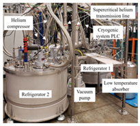
Energies 18 01480 i002[50]
Large-Capacity 30 K Helium Long-Distance Circulating Cooling System20–30 K30 W @ 20 K or 80 W @ 30 KHelium--Gifford-McMahon compressor, uses two copper heat exchangers and liquid helium cooling
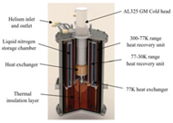
Energies 18 01480 i003[51]
GM Cryocooler Long-Distance Cooling System80 K50 W @ 4.1 kW or 70.5 W @ 6 kWHelium4.1 kW or 6 kW-Cryomech AL125 head, alternating vibration-to-direct flow circulation, 5 m vacuum thermal flexible line
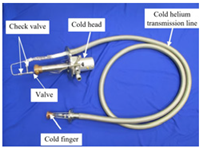
Energies 18 01480 i004[52]
160 W @ 20 K Helium Circulation Low-Temperature System20 K160 W @ 20 KHelium--8 GM cryocoolers, two helium pumps provide loop drive, fully insulated flexible connections-[53]
20 K Superconducting Magnet Circulation System20 K70–100 WHelium-10 g/sCryomech AL325 head, low-loss loop forced flow, 20 bar superfluid heliumEnergies 18 01480 i005[54]
Helium Gas Intercooler Circulation Loop Cooling System27 K100 W @ 27 KHelium-3 m3/h (helium pump flow)2 AL GM cryocoolers, helium pump operating speed 1800 rpm, pipeline length 78 mEnergies 18 01480 i006[55]
Table 6. United States 8 Mvar HTS DSC basic technical parameters table.
ItemParameterItemParameter
Rated Power Pn/Mvar8Field Short Circuit Time Constant τ s c /s0.05
Voltage Un/kV13.8
(Three-phase)
D-Axis Transient Open Circuit Time Constant τ d o /s860
Ambient Temperature T/°C−30~+40D-Axis Subtransient Open Circuit Time Constant τ d o /s0.02
Synchronous Reactance Xd/pu0.37Q-Axis Subtransient Open Circuit Time Constant τ q o /s0.04
Transient Reactance Xd′/pu0.21Field Resistance ra/pu0.007
Subtransient Reactance Xd″/pu0.13Inertia Constant/s1.4
Disclaimer/Publisher’s Note: The statements, opinions and data contained in all publications are solely those of the individual author(s) and contributor(s) and not of MDPI and/or the editor(s). MDPI and/or the editor(s) disclaim responsibility for any injury to people or property resulting from any ideas, methods, instructions or products referred to in the content.

