Article

Development of Efficient Cooling Regimes for the Lining of a Ferroalloy Production Casting Ladle

by
Nazgul Aripova
1,
Evgeniy Prikhodko
1,
Alexandr Nikiforov
1,
Akmaral Kinzhibekova
1,*,
Amangeldy Karmanov
1,
Alexandr Paramonov
2 and
Vladimir Ryndin
3
1
Department of Heat Power Engineering, Toraighyrov University, 64 Lomov Str., Pavlodar 140000, Kazakhstan
2
Department of Heat Power Engineering, Omsk State Technical University, 11 Prospect Mira, Omsk 644050, Russia
3
Department of Mechanics and Oil and Gas Engineering, Toraighyrov University, 64 Lomov Str., Pavlodar 140000, Kazakhstan
*
Author to whom correspondence should be addressed.
Energies 2025, 18(6), 1472; https://doi.org/10.3390/en18061472
Submission received: 11 February 2025 / Revised: 7 March 2025 / Accepted: 14 March 2025 / Published: 17 March 2025
(This article belongs to the Section J: Thermal Management)

Abstract

:
The refractory lining of high-temperature aggregates determines the duration of their operation before major repairs. The ability to retain technological material within the aggregate’s working area is the main factor for its continued operation. The analysis shows that the main reason for the destruction of the lining of ferroalloy production casting ladles is the occurrence of thermal stresses in the processes of heating and cooling the lining. When the stresses exceed the ultimate strength of the refractory material used, the material is destroyed. The greater the magnitude and duration of the excess thermal stresses, the faster the lining destruction occurs. Streamlining thermal regimes is the most low-cost and sufficiently effective way to increase the durability of linings. The development of lining heating and cooling regimes can be carried out on the basis of determining the thermal stress state by calculating the maximum permissible heating rates. The developed regimes allow for working at speeds at which the resulting stresses do not exceed the ultimate strength of the refractory materials. The aim of this study is to develop efficient cooling regimes for the lining of a ferroalloy production casting ladle from the standpoint of the resulting thermal stresses. A method for determining the thermal stresses in the lining has been developed and implemented using Microsoft Excel. This facilitates the use of the developed methodology in production without the need for special skills on the part of operating personnel. Using the developed methodology, the cooling schedules for the lining of ferroalloy production ladles were improved. To reduce temperature unevenness across the lining cross-section, a decision was made to initially heat the outer surface of the lining and cool the inner surface of the lining. Heating the outer surface can be achieved by using the heat of combustion of the ferroalloy gas or the heat of the exhaust gases from the stand for drying and heating casting ladles. Cooling the inner surface of the lining can be achieved by natural convection. The result of the development and implementation of an efficient cooling regime is a reduction in thermal stresses to the required level throughout almost the entire cooling process.

1. Introduction (Problem Statement)

The refractory lining of high-temperature aggregates determines the duration of their operation before major repairs. Such aggregates include casting ladles, tundish ladles, arc furnaces, rotary furnaces, etc. The ability to retain technological material within the aggregate’s working area is the main factor for its continued operation [1,2,3].
The destruction of the refractory lining of high-temperature aggregates may depend on a number of factors. The conducted studies allow us to identify the following conditions that affect the lining damage [4,5,6]:
-
The thermal stresses arising in the lining due to the presence of temperature differences across its cross-section;
-
The influence of demanding operating environments;
-
The mechanical impacts of the upper layers of the lining on the lower ones, as well as the mechanical impacts on the lining from the outside;
-
The dissolution of the lining in a high-temperature operating environment;
-
Other operational factors.
The analysis shows that the main reason for the destruction of the lining of ferroalloy production casting ladles is the occurrence of thermal stresses in the processes of heating and cooling the lining. When the stresses exceed the ultimate strength of the refractory material used, the material is destroyed. The greater the magnitude and duration of these excess thermal stresses, the faster the lining destruction occurs [7,8,9].
To determine the magnitude of thermal stresses in the lining, it is necessary to evaluate the temperature fields of the lining. The data on the temperature distribution in the lining are the basis for the calculation of thermal stresses. The assessment of the temperature fields of the lining is usually carried out on the basis of modeling.
Physical modeling allows us to reduce the scope of the work conducted in the research by using the different materials under study in one model [10].
The data obtained as a result of physical modeling have a fairly high accuracy. In addition, such studies give the advantage of being able to use experimental data for a number of other high-temperature aggregates [11,12]: oxygen converters, steel casting ladles, blast furnace chutes, etc.
Despite the above advantages, the physical modeling of linings has the following disadvantages:
-
The difficulty of taking into account the thermophysical and thermomechanical properties of the refractory lining materials, which change during operation;
-
The data obtained from physical modeling are not always correct due to the low reliability of the scale factor.
Mathematical modeling of the thermal state of linings is widely used for all high-temperature aggregates. Among the positive aspects of mathematical modeling, we can highlight the high accuracy of the results obtained and a wide range of software available for solving various problems [13,14].
Among the methods for calculating the temperature fields in linings, we can distinguish analytical methods [15,16,17] and numerical methods [7,18,19]. Analytical methods are relatively complex, and therefore numerical methods are more often used to calculate the temperature fields of the linings of high-temperature aggregates. The use of the finite element method (FEM) or the finite difference method (FDM) allows for obtaining the temperature distribution in the lining with a sufficiently high accuracy.
Evaluation of the thermal stresses in the lining of high-temperature aggregates is the initial stage for further improving the reliability of their operation. Based on the data on the duration and values of thermal stresses, a conclusion is made about the presence or absence of the destruction of refractories. The next step is to develop measures to eliminate the destructive effects of thermal stress on the lining.
Analysis of the literature shows that the following main methods are used to increase the durability of refractory linings:
-
The use of refractory materials with higher thermal strength characteristics;
-
Streamlining the lining design (including changing the thickness of the refractory layer);
-
Streamlining the thermal operating conditions for the linings of high-temperature aggregates.
To increase the durability of the refractory linings in areas where greater wear is recorded, refractories with improved properties are used [20,21,22,23].
The literature often describes the use of refractories with the addition of components based on zirconium oxide (ZrO2) [24,25]. This improves the thermomechanical properties of refractories and corrosion resistance and leads to an increase in the service life of refractories.
Replacing the refractory material is a fairly effective method, but it requires a significant amount of time (for selecting the material) and financial resources (for purchasing a more expensive material).
The shape of the formed refractories used in linings affects the durability of the lining [26]. In addition, designing linings with different thicknesses can result in an increased service life of the lining, provide cost-effective refractory configurations, improve the efficiency of high-temperature processes and save energy [27,28].
Replacing refractory materials or increasing the thickness of the lining leads to an increase in the mass of the lining. Moreover, increasing the thickness reduces the volume of the aggregate’s operating area and increases the warm-up time to avoid significant temperature differences across the section.
Streamlining thermal regimes is the most low-cost and sufficiently effective way to increase the durability of linings [3,29,30]. The development of heating regimes can be carried out on the basis of determining the thermo-stressed state by calculating the maximum permissible heating rates. The developed heating regimes allow for working at speeds at which the resulting stresses do not exceed the ultimate strength of the refractory materials. In addition, in several cases, the developed regimes reduce the time for heating or cooling the linings [31].
Similar developments are also being carried out for the cooling processes of high-temperature aggregate linings. Calculation of the permissible cooling rates is also important for extending the service life of the lining [32,33].
The use of data on changes in the thermophysical and thermomechanical properties of the refractory materials used allows us to increase the accuracy of the calculations performed. The study of changes in the properties of refractory materials during operation is usually carried out in laboratory conditions [34,35,36,37].
Thus, the development of efficient regimes of heating and cooling the linings of high-temperature aggregates is one of the effective and low-cost ways to increase the durability of linings. To improve the accuracy of the calculations, it is necessary to take into account changes in the thermophysical and thermomechanical properties of the refractory materials used.

2. Materials and Methods

Let us consider the process of cooling the lining of a ferroalloy production casting ladle. A casting ladle with a capacity of 40 tons has a lining that consists of two layers of chamotte bricks that are 160 mm thick. The lining made of chamotte bricks of the ShKU-32 brand (JSC “Borovichi Refractories Plant”, Borovichi, Russia) does not have a binding solution or heat-insulating filling.
The process of cooling the lining of the casting ladles is carried out under the conditions of natural convection of the smelting shop; no special equipment is used for cooling.
The first stage of developing efficient lining cooling regimes is the calculation of temperature fields across the cross-section of the lining. Based on the obtained temperature values, the thermal stresses in the lining are then calculated. The obtained thermal stress values are compared with the ultimate strength of the refractory materials used. Next, a conclusion is made about the cooling rate of the lining.
A mathematical description of the lining cooling process and a method for determining the thermal stresses are presented by the authors in [9].
In general, the process of non-stationary thermal conductivity in the lining is described by the Fourier’s heat equation:
ρ c T t = x λ T x + y λ T y + z λ T z + Q w x , y , z , T
where
ρ is the density of the material, kg/m3;
c is the specific heat capacity of the material, kJ/(kg·°C);
λ is the thermal conductivity coefficient of the material, kJ/(m·°C);
Qw is the wattage of the internal heat sources, W/m3.
Let us introduce the following assumptions:
-
The lining is homogeneous and isotropic;
-
The temperature field is one-dimensional;
-
There are no internal heat sources.
Taking into account the accepted assumptions, the mathematical formulation of the problem will have the following form:
T t = a 2 T x 2 ,       0 < x < H ,
where a is the thermal diffusivity coefficient, m2/s.
The mathematical model cannot be applied in the case of non-uniform temperature distribution along the height or circumference of the ladle. The above assumptions are also not applicable when refractory materials with anisotropic properties are used.
The initial conditions can be written as follows:
t = 0; T = f(x); 0 ≤ xH;
Based on the measured temperatures of the inner and outer surfaces of the lining, we will have the boundary condition of the first type:
x = 0; T = T1; t > 0;
x = H; T = Tn; t > 0
At the boundary of the two layers, there is a boundary condition of the fourth type:
T1(t, x*) = T2(t, x*),
λ · T 1 x x = x * = λ · T 2 x x = x *
The solution to this problem was carried out numerically on the basis of an implicit difference scheme [38], based on the application of the tridiagonal matrix algorithm under boundary conditions on the outer surface of the lining. This method has a number of advantages. Firstly, the calculation starts from the outer boundary, and therefore the computational process can be completed when the temperature at the outer boundary satisfies the given condition. The temperature of the outer surface of the ladle, obtained by measurements, is used as an external condition. Secondly, the implicit difference scheme is stable at any time and spatial step. In order to assess the adequacy of the developed mathematical model of the lining of the casting ladle, a comparison was made between the temperature values of the inner surface of the lining that were obtained as a result of the calculation and those that were measured during the cooling process. The measurements were carried out using a Kelvin Compact 1500/175 (JSC “EUROMIX”, Moscow, Russia) infrared pyrometer (temperature measurement range: up to 1500 °C; measurement error: 1%). The difference between the calculated and measured temperatures does not exceed 3%. The calculation of thermal stresses in the lining was carried out using Formula [9]:
σ = α E 1 v T y , t
This method of determining temperature stresses is relatively simple, which allows it to be implemented in the Microsoft Excel program. This facilitates the use of the developed methodology in production without the need for special skills on the part of operating personnel.
The calculation of thermal stresses showed that the cooling process is accompanied by the occurrence of thermal stresses, the magnitude of which exceeds the ultimate strength of the refractory materials used.
When the lining cools, the magnitude of thermal stresses changes across its thickness and over time. For the convenience of visual assessment of the obtained thermal stresses, three-dimensional graphs of the stress distribution across the thickness of the refractory were made (Figure 1 and Figure 2).
A significant temperature difference across the lining cross-section occurs due to the long period of time between the draining of the molten metal and the installation of the ladle for cooling. In the case under consideration, 40 min passed from the moment the melt was drained from the ladle until it was placed for cooling. The temperature of the inner surface of the lining at the start of cooling was 1250 °C; the temperature of the outer surface was 400 °C. Temperature measurements were taken in the zones of maximum temperature (at the level of 5–7 rows of lining masonry).
Figure 1 shows a graph of the distribution of thermal stresses in the lining of a casting ladle with refractories that have not been in operation. The following parameters were adopted for the calculations: time step—300 s; coordinate step—10 mm. The zones in which thermal stresses exceed the ultimate strength of the ShKU-32 chamotte (JSC “Borovichi Refractories Plant”, Borovichi, Russia) are marked in red. The red area at the top shows that at the initial stage of cooling (in the first 40 min), the compressive stresses exceed the ultimate compressive strength. This occurs directly on the inner surface of the lining at a depth of up to 20 mm. The maximum values of thermal compressive stresses are observed at the initial moment of cooling and are 1.27 times higher than the ultimate compressive strength of the ShKU-32 chamotte.
As can be seen from the graph, during the cooling process of the ladle, the zone of excess thermal tensile stresses is significantly larger than the zone of excess thermal compressive stresses. Tensile stresses exceeding 6 MPa act on the outer surface of the lining at a depth of up to 80 mm. The duration of action of these stresses was 250 min. The maximum value of thermal tensile stress occurred at the initial moment of cooling and exceeded the ultimate tensile strength by 4.4 times.
Similar results were obtained for refractories that have been in operation for three fuses (Figure 2). At the initial stage, the compressive stresses exceeded the ultimate strength of the refractories for 10 min on the inner surface of the lining at a depth of up to 20 mm. The maximum value of the thermal compressive stresses is 1.28 times higher than the ultimate compressive strength.
Excessive tensile stresses were observed over a significant period of time (250 min) on the outer surface of the lining at a depth of up to 50 mm. The maximum value of the arising thermal tensile stresses was recorded at the initial moment of cooling. The maximum stress value is 3.19 times higher than the ultimate tensile strength of the ShKU-32 chamotte.
The resulting thermal stresses are proportional to the significant temperature differences inside the lining, which correspond to its high cooling rates. For example, the period from 0:00 to 0:40 was characterized by a high cooling rate of the inner surface of the lining (about 150 °C/h), which was accompanied by significant thermal stresses. The further cooling process proceeds at lower speeds and with lower thermal stresses.
The second stage of developing efficient lining cooling regimes is the selection of temperatures for the cooling process. The developed methodology allows for obtaining the values of thermal stresses at a selected cooling rate and adjusting this rate if necessary. The developed cooling schedules for the lining of a ferroalloy production casting ladle must perform two main functions:
-
Firstly, minimizing the thermal stresses that arise in the lining during cooling;
-
Secondly, minimizing the cooling time.
To reduce temperature unevenness across the lining cross-section, a decision was made to heat the outer surface of the lining at the initial moment in time and cool the inner surface of the lining. Heating the outer surface can be achieved by using the heat of the combustion of the ferroalloy gas or the heat of the exhaust gases from the stand for drying and heating the casting ladles. Cooling the inner surface of the lining can be achieved by natural convection. To calculate the temperature fields, it was determined that heating the outer surface of the lining should be carried out by a gas with a temperature of 700 °C. This temperature was adopted as a result of calculations which showed that in order to reduce thermal tensile stresses at the initial stage of cooling, it is necessary to heat the outer wall of the lining.

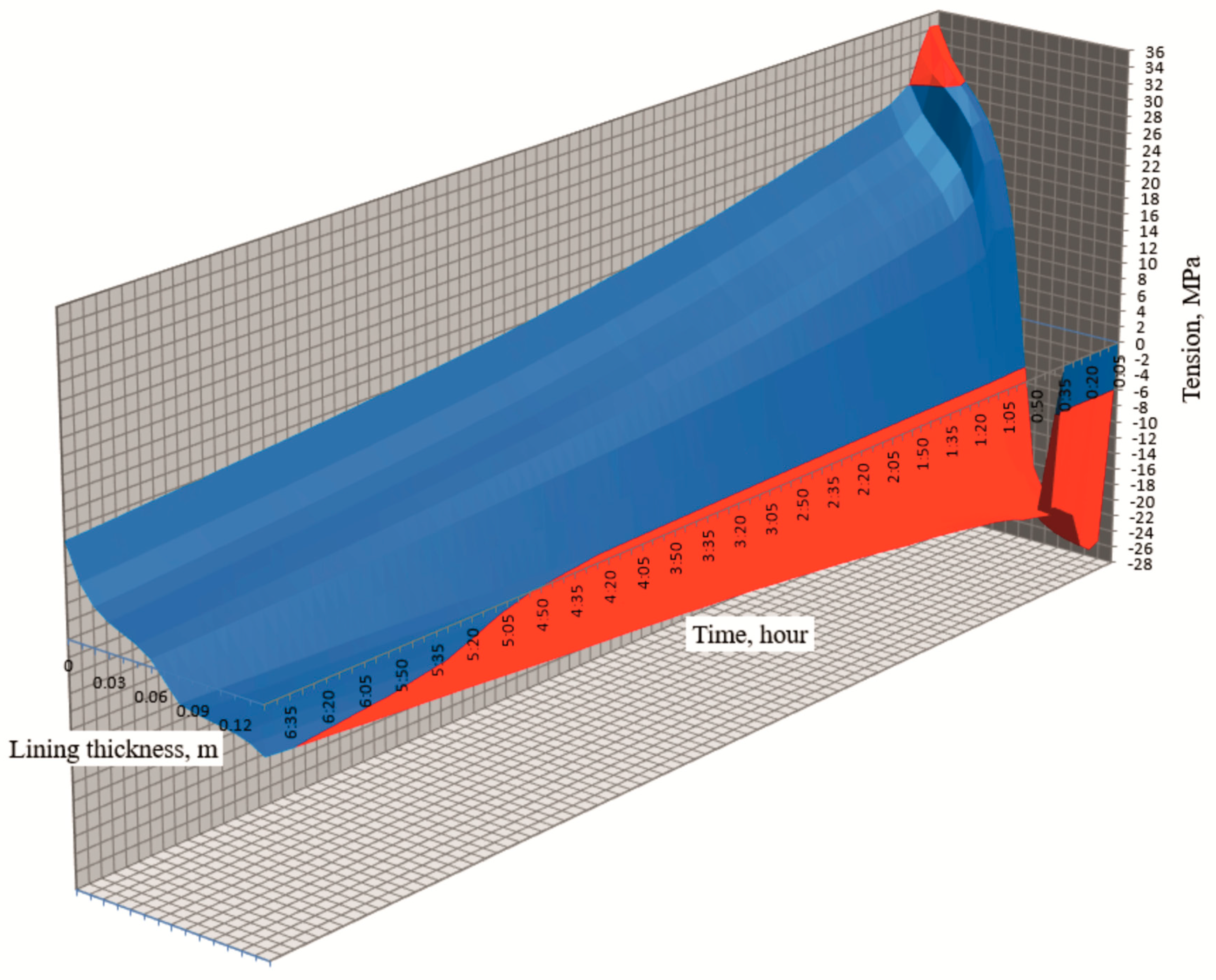
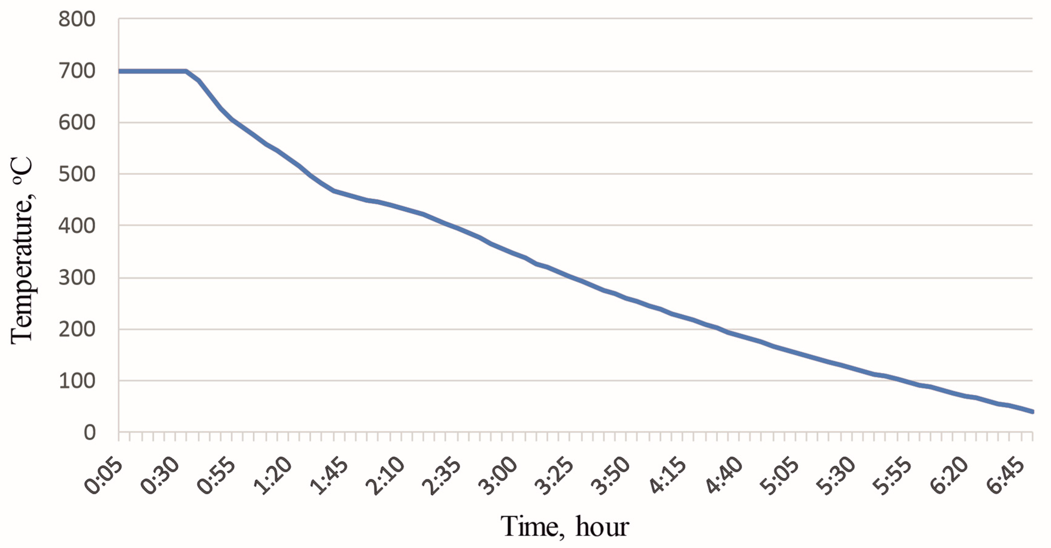
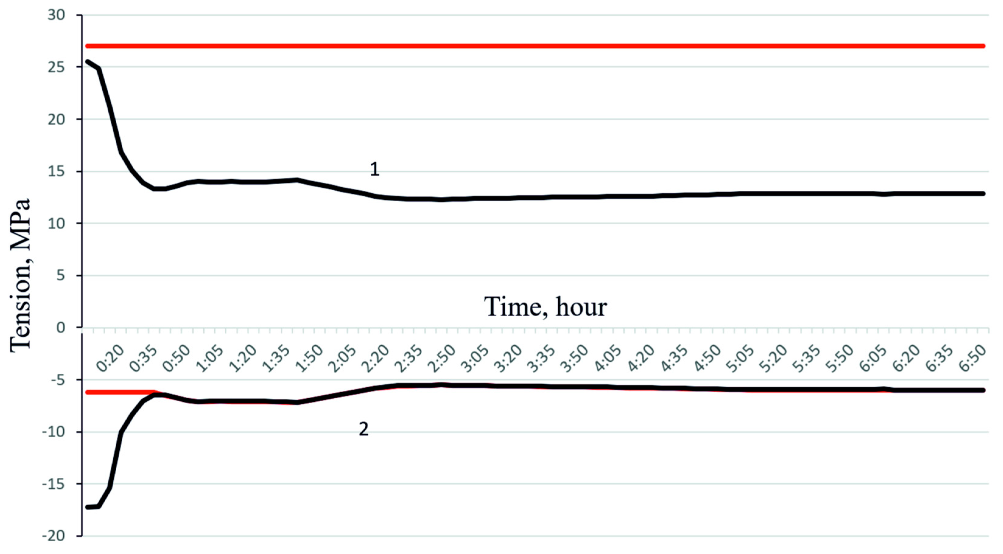
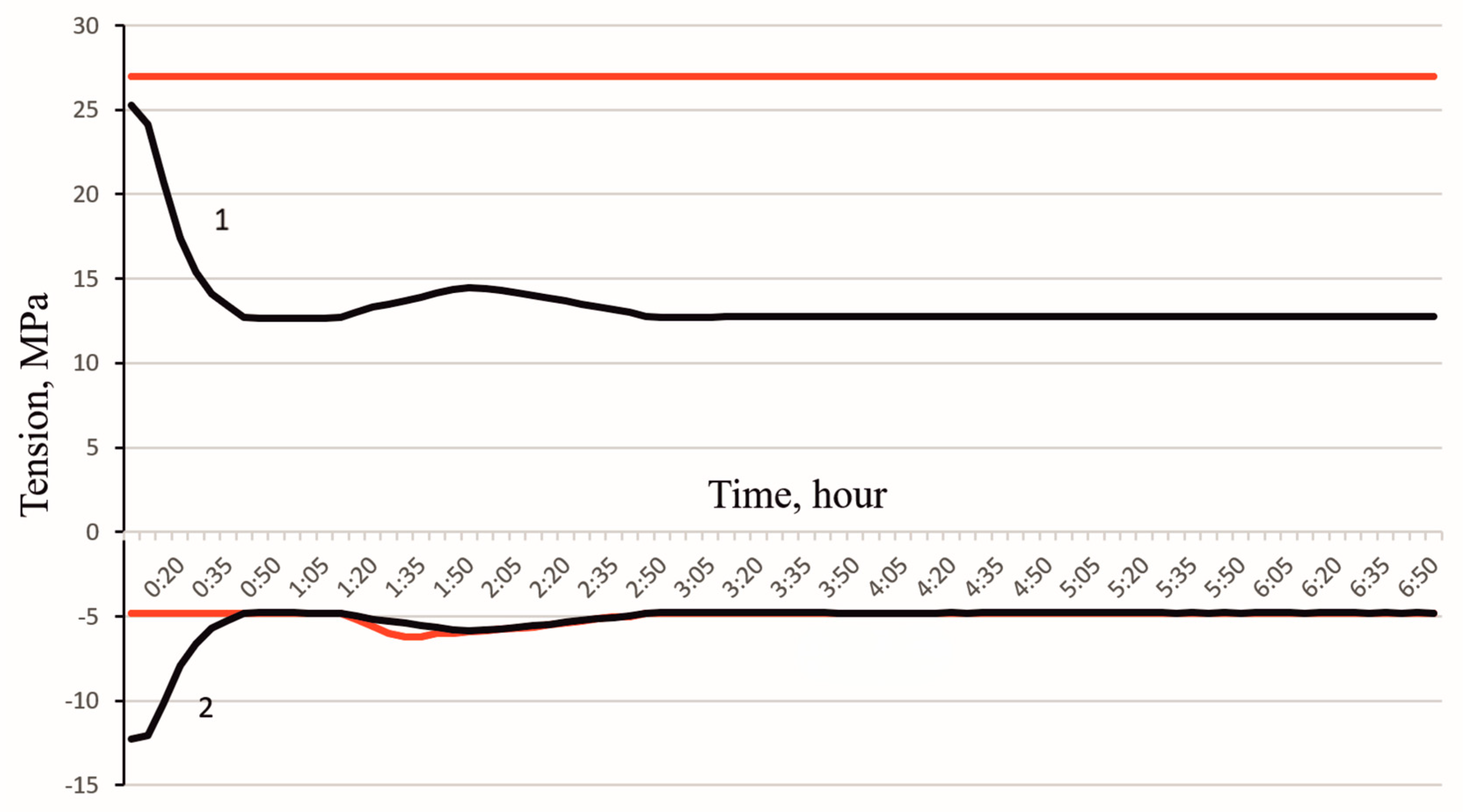
3. Results and Discussion

Figure 3 shows the developed cooling schedule for the lining of a casting ladle in the case of using new refractories. The horizontal axis represents the time elapsed since the start of cooling. The vertical axis shows the temperature of the inner surface of the lining.
The average rate of the temperature decrease was about 2 °C/min. The maximum cooling rate was 200 °C/h in the time interval from 0:40 to 1:40. The total cooling time of the casting ladle lining was reduced from 19 h 30 min to 6 h 50 min. The values of the thermal stresses that correspond to the developed lining cooling schedule are shown in Figure 4.
In Figure 4, the red lines correspond to the ultimate strength value of the chamotte refractory used. The upper red line at 27 MPa is the ultimate compressive strength of the refractory. The lower red line at 6 MPa is the ultimate tensile strength taking into account its temperature dependence at this stage of cooling [40].
Curve 1 shows the values of the thermal compressive stresses during the cooling process and curve 2 shows the values of the thermal tensile stresses during the cooling process.
A factor that determines the values of generated thermal stresses is the temperature difference across the thickness of the lining. As can be seen from the graph, excess thermal tensile stresses are observed in the first 40 min of cooling. During further cooling, the rate of temperature reduction is calculated in such a way that the resulting thermal tensile stresses do not exceed the ultimate strength of the ShKU-32 chamotte.
Similarly, a cooling schedule was developed for the lining of casting ladles with refractories that have been in operation for three fuses (Figure 5). The initial stage of the schedule also has a period during which it is necessary to heat the outer side of the lining to reduce thermal tensile stresses. The duration of this stage is 25 min.
The cooling graph in Figure 5 is similar in nature to the graph shown in Figure 3. Despite the different cooling rates in individual periods of the developed schedule, the total cooling time of the lining of the casting ladle also amounted to 6 h 50 min.
Figure 6 shows the values of thermal stresses that correspond to the developed schedule for cooling the lining with refractories that have been in operation for three fuses.
It should be noted that the time moment 01:15–01:45 is characterized by a slight decrease in the cooling rate. It should be noted that cooling does not occur at the maximum permissible speed. Reducing the speed in this period is necessary to maintain the average cooling rate. If the cooling process is carried out at the time 01:15–01:45 with maximum speeds, then in the future, it is necessary to carry out cooling with a slight decrease in speed. This is explained by the decrease in the ultimate tensile strength of chamotte at a given temperature. Thus, slowing down the cooling at the time point 01:15–01:45 allows cooling to be carried out at higher speeds and leads to time savings.
The developed cooling schedule for the lining of a casting ladle with refractories that have not been in operation allows for a reduction in the total cooling time from 19 h 30 min to 10 h 10 min.
The developed cooling schedule for the lining of casting ladles with refractories that have been in operation for three fuses also allows the total cooling time to be reduced to 9 h 50 min.

4. Conclusions and Future Research Direction

As a result of the conducted research, it was shown that with the existing cooling schedule of the lining of the casting ladle, excessive thermal stresses arise.
To develop an efficient cooling schedule, cooling rates were determined for the initial stage (up to 6 h 50 min). It is during this period of time that the thermal stresses that arise can have a destructive effect on the lining.
Uncontrolled cooling of the lining during transportation of the ladle to the cooling site over a period of 40 min leads to the occurrence of a significant temperature difference across its cross-section. To reduce temperature unevenness across the lining cross-section, it is proposed to heat the outer surface of the lining using the heat of the combustion of the ferroalloy gas and cool the inner surface of the lining using natural convection at the initial stage of the cooling process.
The result of developing and implementing an efficient cooling schedule is a reduction in thermal stresses to the required level throughout almost the entire cooling process (except for the first 25 min). It should be noted that in the first 25 min, the tensile stresses that arose (for refractories that have been in operation for three fuses) were reduced by more than 2.8 times.
The next stage of research will be the development of a design for a device for cooling ferroalloy production casting ladles. The device being developed must cool the lining of the ladles with control of the temperature of the inner and outer surfaces of the lining. The adjustment of the temperatures of the inner and outer surfaces of the lining will be carried out fully automatically by changing the flow rates of the gases that make up the cooling medium. It is proposed to use a mixture of air and combustion products of the ferroalloy gas as a cooling medium.

Author Contributions

Conceptualization, N.A. and E.P.; methodology, N.A., E.P. and A.N.; validation, N.A., E.P., A.N., A.P. and V.R.; formal analysis, A.N. and A.K. (Akmaral Kinzhibekova); investigation, E.P., A.K. (Amangeldy Karmanov) and A.P.; resources, N.A., A.P. and A.K. (Amangeldy Karmanov); data curation, E.P., N.A. and A.K. (Akmaral Kinzhibekova); writing—original draft preparation, N.A. and E.P.; writing—review and editing, A.N., A.K. (Akmaral Kinzhibekova), V.R. and A.P.; visualization, E.P. and N.A.; supervision, N.A., E.P. and A.N.; project administration, A.K. (Akmaral Kinzhibekova). All authors have read and agreed to the published version of the manuscript.

Funding

This research is funded by the Science Committee of the Ministry of Science and Higher Education of the Republic of Kazakhstan (Grant No. AP19675777).

Data Availability Statement

Data are contained within the article.

Conflicts of Interest

The authors declare no conflicts of interest.

References

  1. Guillin-Estrada, W.D.; Albuja, R.; Davila, I.B.; Rueda, B.S.; Corredor, L.; Gonzalez-Quiroga, A.; Maury, H. Transient operation effects on the thermal and mechanical response of a large-scale rotary kiln. Results Eng. 2022, 14, 100396. [Google Scholar] [CrossRef]
  2. Pagliosa, C.; Resende, C.; Da Luz, A.; Pandolfelli, V. Designing stronger and tougher MgO-C bricks for basic oxygen furnace (BOF). Refract. World Forum 2017, 9, 89–93. [Google Scholar]
  3. Kukartsev, V.A.; Kukartsev, V.V.; Tynchenko, V.S.; Kurashkin, S.O.; Sergienko, R.B.; Tynchenko, S.V.; Panfilov, I.A.; Eremeeva, S.V.; Panfilova, T.A. Study of the Influence of the Thermal Capacity of the Lining of Acid Melting Furnaces on Their Efficiency. Metals 2023, 13, 337. [Google Scholar] [CrossRef]
  4. Demeter, J.; Buľko, B.; Demeter, P.; Hrubovčáková, M. Evaluation of Factors Affecting the MgO–C Refractory Lining Degradation in a Basic Oxygen Furnace. Appl. Sci. 2023, 13, 12473. [Google Scholar] [CrossRef]
  5. Aripova, N.M.; Nikiforov, A.S.; Paramonov, A.M.; Prikhod’ko, E.V.; Kinzhibekova, A.K.; Karmanov, A.E. Assessment of Reliability and Technical Risks in the Operation of Heat Engineering Units. Refract. Ind. Ceram. 2023, 64, 206–213. [Google Scholar] [CrossRef]
  6. Santos, D.P.; Pelissari, P.I.G.; de Oliveira, B.S.; Leiva, D.R.; de Mello, R.F.; Pandolfelli, V.C. Materials selection of furnace linings with multi-component refractory ceramics based on an evolutionary screening procedure. Ceram. Int. 2020, 46, 4113–4125. [Google Scholar] [CrossRef]
  7. Fang, L.; Su, F.; Kang, Z.; Zhu, H. Finite element (FE) analysis of thermal stress in production process of multi-layer lining ladle. Case Stud. Therm. Eng. 2024, 57, 104307. [Google Scholar] [CrossRef]
  8. Wang, L.; Chen, L.; Yuan, F.; Zhao, L.; Li, Y.; Ma, J. Thermal Stress Analysis of Blast Furnace Hearth with Typical Erosion Based on Thermal Fluid-Solid Coupling. Processes 2023, 11, 531. [Google Scholar] [CrossRef]
  9. Prikhodko, E.; Nikiforov, A.; Kinzhibekova, A.; Aripova, N.; Karmanov, A.; Ryndin, V. Analysis of the Cooling Modes of the Lining of a Ferroalloy-Casting Ladle. Energies 2024, 17, 1229. [Google Scholar] [CrossRef]
  10. Akishev, A.K.; Fomenko, S.M.; Tolendiuly, S. Effect of Refractory Thermal Stresses and Parameters on Development of the Internal Temperature Field. Refract. Ind. Ceram. 2020, 60, 561–565. [Google Scholar] [CrossRef]
  11. Smirnov, A.N.; Smirnov, A.N.; Nemsadze, G.G.; Sharandin, K.N. Rotary Furnace for Comparative Evaluation of Heating Unit Refractory Object Erosion Resistance. Refract. Ind. Ceram. 2018, 59, 227–230. [Google Scholar] [CrossRef]
  12. Molchanov, L.; Golub, T.; Synehin, Y.; Semykin, S. Physical Model of Influence of CaO–FeO–SiO2 Powder Fraction on the Heat Transfer from Torch. Sci. Innov. 2022, 18, 64–71. [Google Scholar] [CrossRef]
  13. Istadi, I.; Bindar, Y. Improved cooler design of electric arc furnace refractory in mining industry using thermal analysis modeling and simulation. App. Therm. Eng. 2014, 73, 1129–1140. [Google Scholar] [CrossRef]
  14. Samadi, S.; Jin, S.; Gruber, D.; Harmuth, H. Thermomechanical finite element modeling of steel ladle containing alumina spinel refractory lining. Finite Elem. Anal. Des. 2022, 206, 103762. [Google Scholar] [CrossRef]
  15. Wang, X.; Zhang, W.; Li, Q.; Wei, Z.; Lei, W.; Zhang, L. An analytical method to estimate temperature distribution of typical radiant floor cooling systems with internal heat radiation. Energy Explor. Exploit. 2021, 39, 1283–1305. [Google Scholar] [CrossRef]
  16. Zhang, S.; Yue, Z.; Sun, T.; Zhang, J.; Huang, B. Analytical determination of the soil temperature distribution and freezing front position for linear arrangement of freezing pipes using the undetermined coefficient method. Cold Reg. Sci. Technol. 2021, 185, 103253. [Google Scholar] [CrossRef]
  17. Gao, S.; Tang, C.; Luo, W.; Han, J.; Teng, B. A New Analytical Model for Calculating Transient Temperature Response of Vertical Ground Heat Exchangers with a Single U-Shaped Tube. Energies 2020, 13, 2120. [Google Scholar] [CrossRef]
  18. Damhof, F.; Brekelmans, W.A.M.; Geers, M.G.D. Predictive FEM simulation of thermal shock damage in the refractory lining of steelmaking installations. J. Mater. Process. Technol. 2011, 211, 2091–2105. [Google Scholar] [CrossRef]
  19. Ali, M.; Sayet, T.; Gasser, A.; Blond, E. Transient Thermo-Mechanical Analysis of Steel Ladle Refractory Linings Using Mechanical Homogenization Approach. Ceramics 2020, 3, 171–189. [Google Scholar] [CrossRef]
  20. Peng, W.; Chen, Z.; Yan, W.; Schafföner, S.; Li, G.; Li, Y.; Jia, C. Advanced lightweight periclase-magnesium aluminate spinel refractories with high mechanical properties and high corrosion resistance. Constr. Build. Mater. 2021, 291, 123388. [Google Scholar] [CrossRef]
  21. Wu, G.; Yan, W.; Schafföner, S.; Dai, Y.; Han, B.; Li, T.; Ma, S.; Li, N.; Li, G. A comparative study on the microstructures and mechanical properties of a dense and a lightweight magnesia refractory. J. Alloys Compd. 2019, 796, 131–137. [Google Scholar] [CrossRef]
  22. Pereira, C.I.; Santos, M.F.; Angélico, R.A.; Moreira, M.H.; Braulio, M.; Iwanaga, T.; Pandolfelli, V.C. Insights into thermomechanical behavior and design parameters of alumina calciner refractory lining. Ceram. Int. 2024, 50, 44008–44016. [Google Scholar] [CrossRef]
  23. Slovikovskii, V.V.; Gulyaeva, A.V. Corrosion-Erosion-Resistant Carbon-Containing Refractories for Nonferrous Metallurgy Units. Refract. Ind. Ceram. 2016, 56, 490–493. [Google Scholar] [CrossRef]
  24. Ceylantekin, R.; Aksel, C. Improvements on corrosion behaviours of MgO–spinel composite refractories by addition of ZrSiO4. J. Eur. Ceram. Soc. 2012, 32, 727–736. [Google Scholar] [CrossRef]
  25. Chen, D.; Huang, A.; Gu, H.; Zhang, M.; Shao, Z. Corrosion of Al2O3–Cr2O3 refractory lining for high-temperature solid waste incinerator. Ceram. Int. 2015, 41, 14748–14753. [Google Scholar] [CrossRef]
  26. Aksel’rod, L.M.; Rodgol’ts, Y.S.; Paivin, A.A.; Kazakov, V.V.; Toporkova, T.I.; Rossikhina, G.S. Improving the Steel Ladle Lining at the Volzhskii Tube-Making Plant Joint-Stock Co. Refract. Ind. Ceram. 2004, 45, 150–153. [Google Scholar] [CrossRef]
  27. Hou, A.; Jin, S.; Harmuth, H.; Gruber, D. A Method for Steel Ladle Lining Optimization Applying Thermomechanical Modeling and Taguchi Approaches. JOM. 2018, 70, 2449–2456. [Google Scholar] [CrossRef]
  28. Kononov, V.A.; Kononov, N.V.; Skrobov, S.N.; Salomakhin, O.A. Improvement in the steel-pouring ladle lining life in open-hearth production of ZAO metallurgical plant Petrostal. Refract. Ind. Ceram. 2009, 50, 89–93. [Google Scholar] [CrossRef]
  29. Slovikovskii, V.V.; Gulyaeva, A.V. Effect of Heating Unit Lining Warm-Up Regimes and Refractory Storage Duration on Refractory Lining Life. Refract. Ind. Ceram. 2015, 56, 225–229. [Google Scholar] [CrossRef]
  30. Dai, Y.; Zhu, H.; Zhu, Q.; Wang, F.; Liao, N.; Li, Y.; Konietzky, H.; Aneziris, C.G. Impact of fast heating and cooling on the mechanical behaviour of alumina-magnesia refractory castables. Ceram. Int. 2023, 49, 36507–36515. [Google Scholar] [CrossRef]
  31. Prikhod’ko, E.V. Analysis of Methods for Heating the Lining of High-Temperature Units. Refract. Ind. Ceram. 2021, 62, 463–466. [Google Scholar] [CrossRef]
  32. Ramanenka, D.; Gustafsson, G.; Jonsén, P. Influence of heating and cooling rate on the stress state of the brick lining in a rotary kiln using finite element simulations. Eng. Fail. Anal. 2019, 105, 98–109. [Google Scholar] [CrossRef]
  33. Krasnyansky, M.V.; Katz, Y.L.; Bershitsky, I.M. Efficiency of electrically heating the lining of steel-pouring ladles. Metallurgist 2012, 56, 357–365. [Google Scholar] [CrossRef]
  34. Schmitt, N.; Berthaud, Y.; Hernandez, J.F.; Meunier, P.; Poirier, J. Damage of monolithic refractory linings in steel ladles during drying. Br. Ceram. Trans. 2004, 103, 121–133. [Google Scholar] [CrossRef]
  35. Oliveira, R.G.; Rodrigues, J.P.C.; Pereira, J.M. Numerical simulations on refractory linings for steel casting vessels. Fire Saf. J. 2023, 138, 103794. [Google Scholar] [CrossRef]
  36. Luz, A.P.; Souza, T.M.; Pagliosa, C.; Brito, M.A.M.; Pandolfelli, V.C. In situ hot elastic modulus evolution of MgO–C refractories containing Al, Si or Al–Mg antioxidants. Ceram. Int. 2016, 42, 9836–9843. [Google Scholar] [CrossRef]
  37. Nikiforov, A.S.; Prikhod’ko, E.V.; Kinzhibekova, A.K.; Karmanov, A.E. Investigation of the Dependence of Refractory Thermal Conductivity on Impregnation with a Corrosive Medium. Refract. Ind. Ceram. 2020, 60, 463–467. [Google Scholar] [CrossRef]
  38. Luo, B.; Li, G.; Kong, J.; Jiang, G.; Sun, Y.; Liu, Z.; Chang, W.; Liu, H. Simulation Analysis of Temperature Field and Its Influence Factors of the New Structure Ladle. Appl. Math. Inform. Sci. 2017, 11, 589–599. [Google Scholar] [CrossRef]
  39. Aripova, N.M. Increasing the Energy Efficiency of the Filling Buckets by Rationalizing the Cooling Modes of the Lining. Ph.D. Thesis, Toraighyrov University, Pavlodar, Kazakhstan, 19 June 2024. [Google Scholar]
  40. Prikhodko, E.; Nikiforov, A.; Kinzhibekova, A.; Paramonov, A.; Aripova, N.; Karmanov, A. Analysis of the Effect of Temperature on the Ultimate Strength of Refractory Materials. Energies 2023, 16, 6732. [Google Scholar] [CrossRef]
Figure 1. Distribution of thermal stresses in the lining of a casting ladle during its cooling (with refractories that have not been in operation).
Energies 18 01472 g001
Figure 2. Distribution of thermal stresses in the lining of a casting ladle during its cooling (with refractories that have been in operation for three fuses).
Energies 18 01472 g002
Figure 3. Cooling schedule of the lining of a casting ladle (with refractories that have not been in operation) [39].
Energies 18 01472 g003
Figure 4. Values of thermal stresses arising with the developed lining cooling schedule (with refractories that have not been in operation) [39].
Energies 18 01472 g004
Figure 5. Cooling schedule of the lining of the casting ladle (with refractories that have been in operation for three fuses) [39].
Energies 18 01472 g005
Figure 6. Values of thermal stresses arising from the developed lining cooling schedule (with refractories that have been in operation for three fuses) [39].
Energies 18 01472 g006
Disclaimer/Publisher’s Note: The statements, opinions and data contained in all publications are solely those of the individual author(s) and contributor(s) and not of MDPI and/or the editor(s). MDPI and/or the editor(s) disclaim responsibility for any injury to people or property resulting from any ideas, methods, instructions or products referred to in the content.

