
Investigation of Flow Characteristics in Rotating Distributary and Confluence Cavities


Abstract
1. Introduction
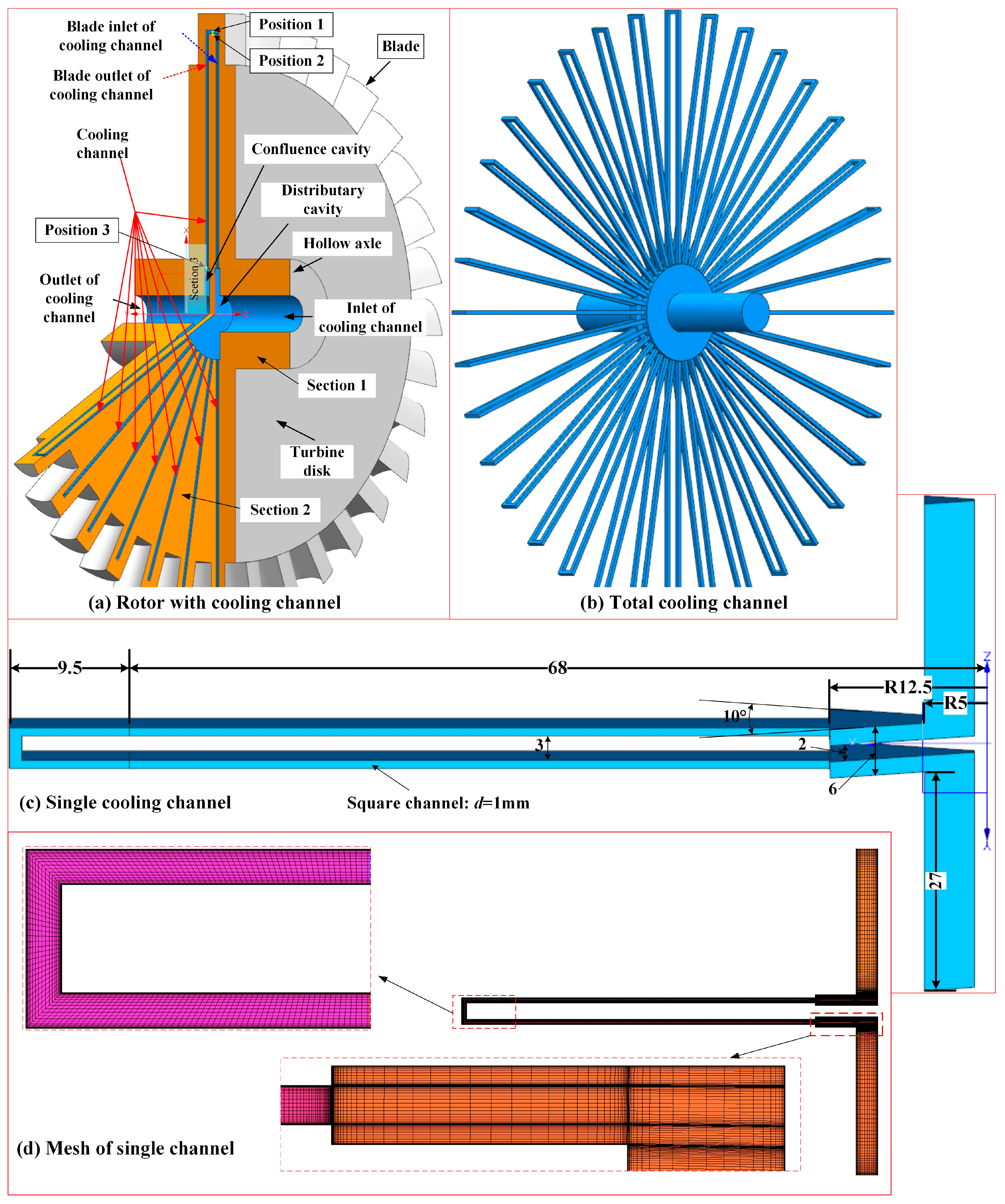
2. Physical Model
3. Numerical Details
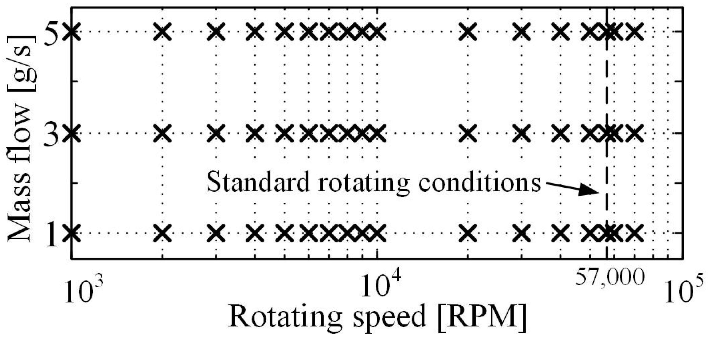
3.1. Summary of the Working Conditions
3.2. Physical Properties of the Working Fluid
3.3. Governing Equations
3.4. Boundary Conditions and CFD Configurations
3.5. CFD Model Validation
3.6. Grid Independence Verification
3.7. Uncertainty of the CFD Model and Sensitivity Analysis
4. Results and Discussion
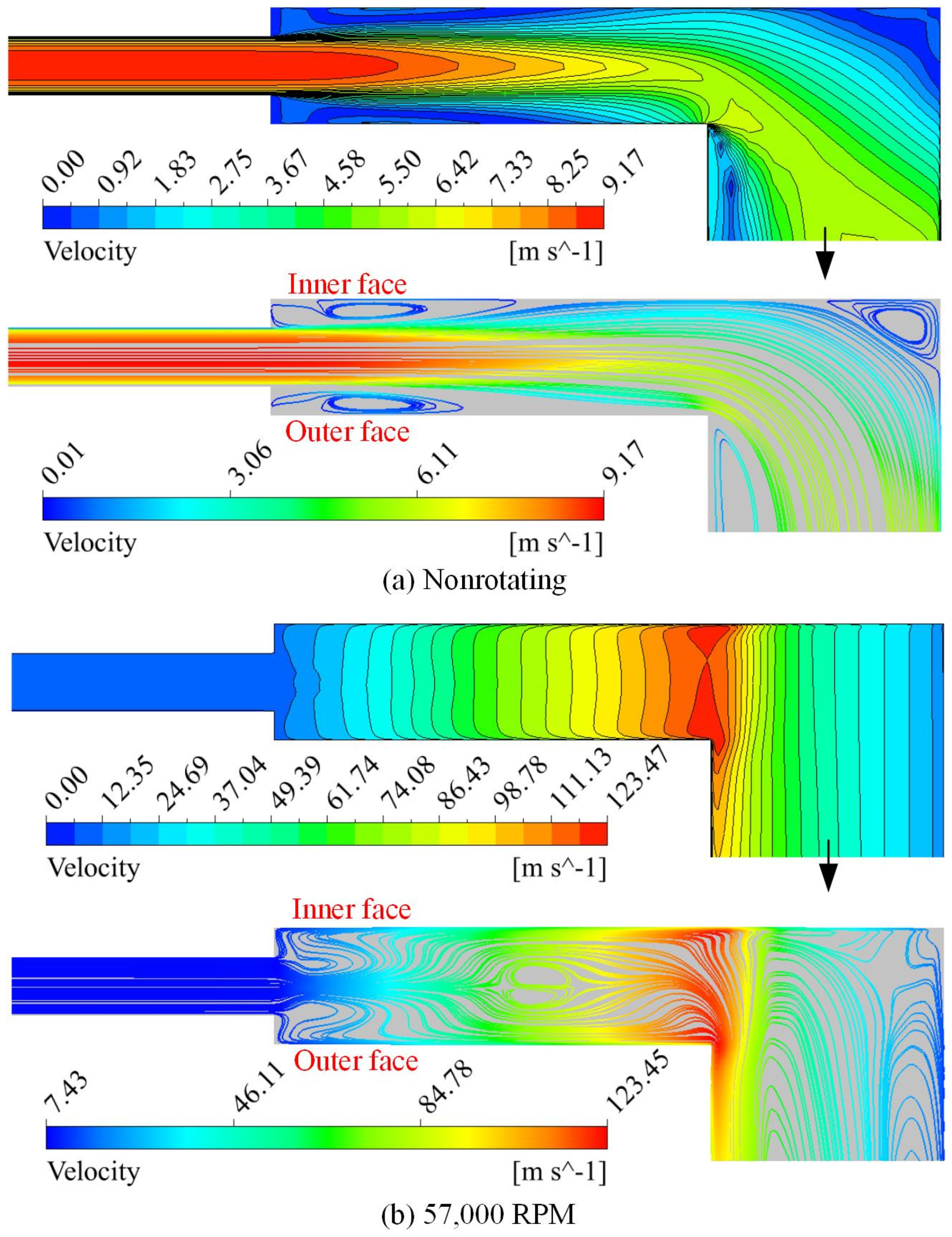
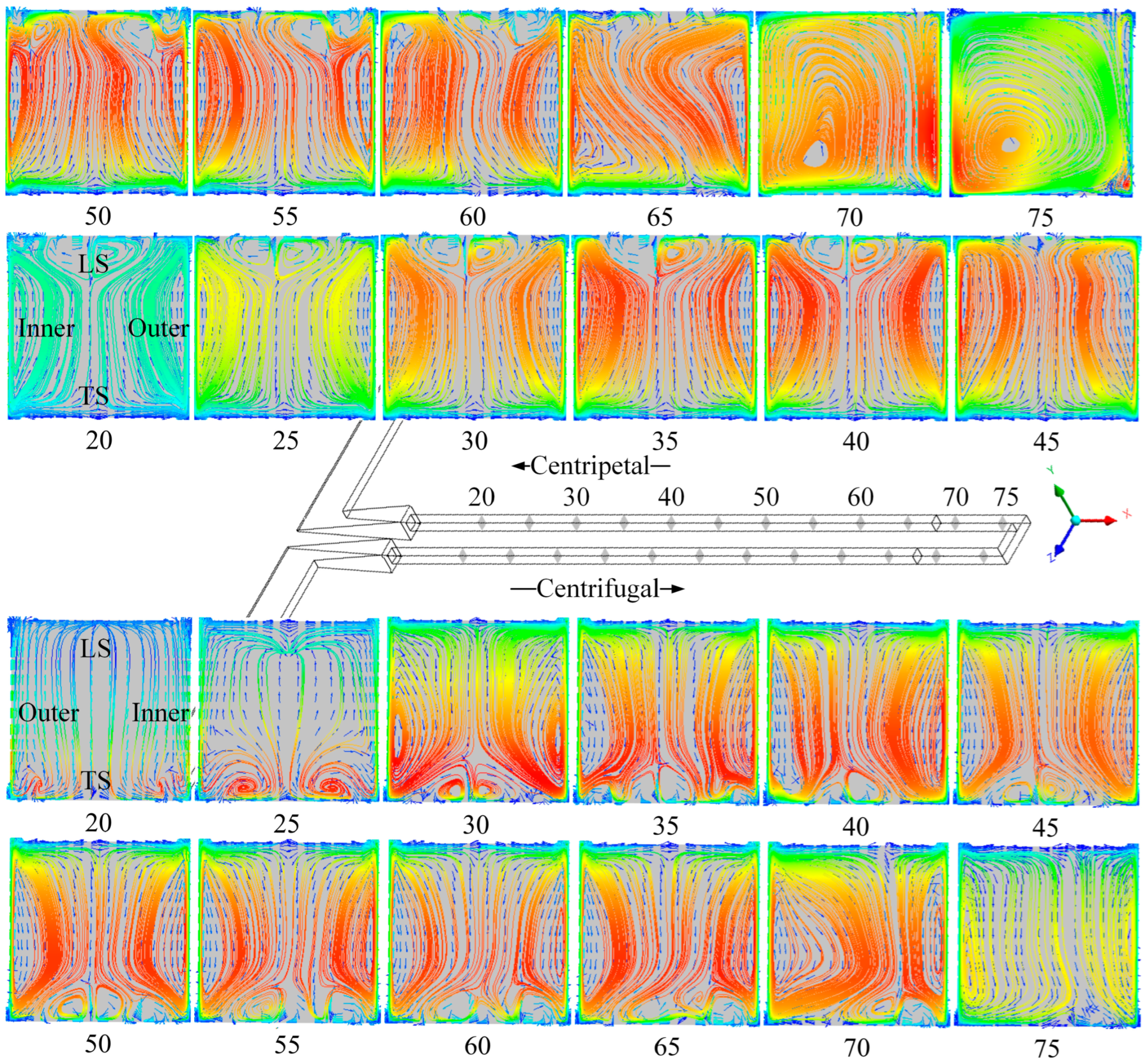
4.1. Flow Characteristics in the Distributary Cavity
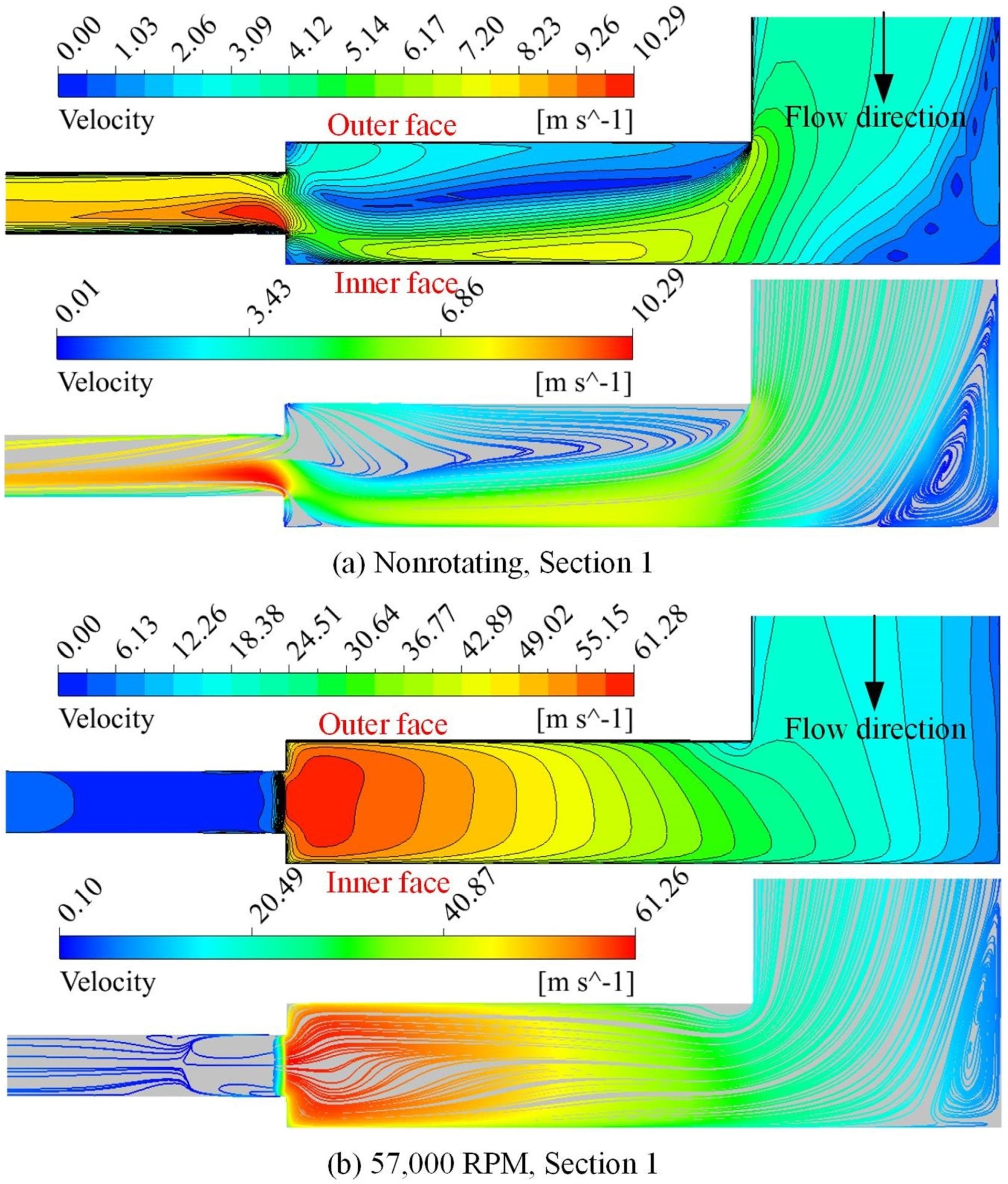
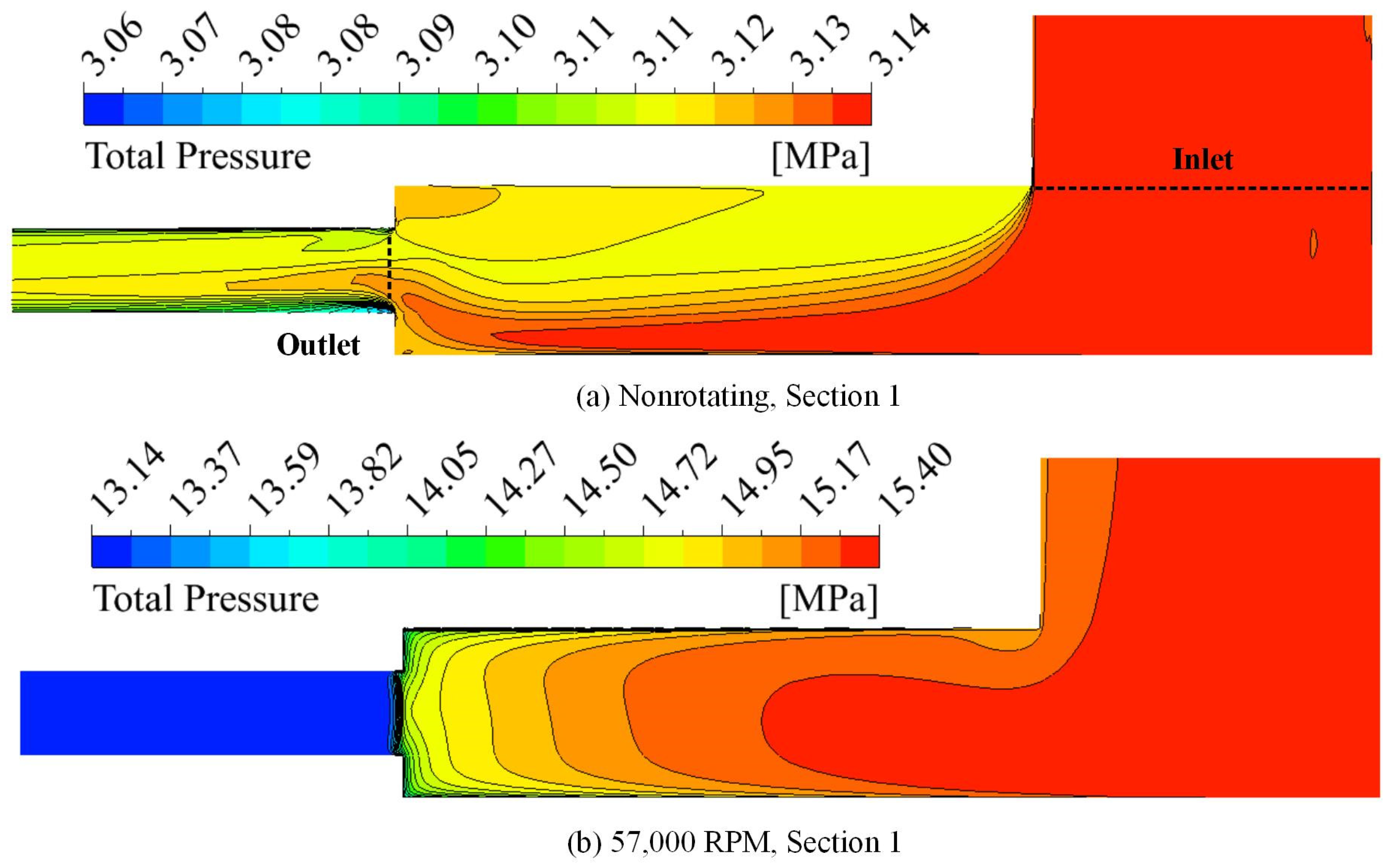
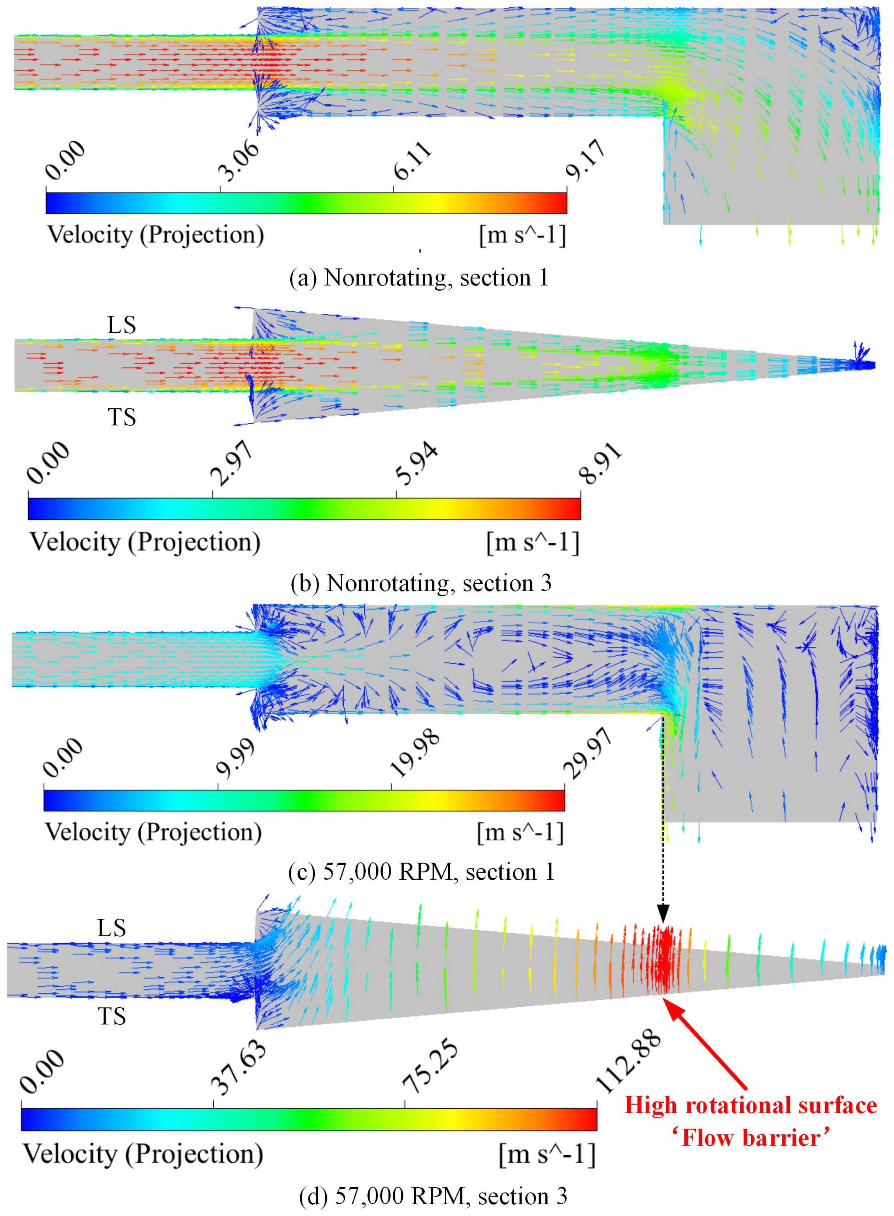
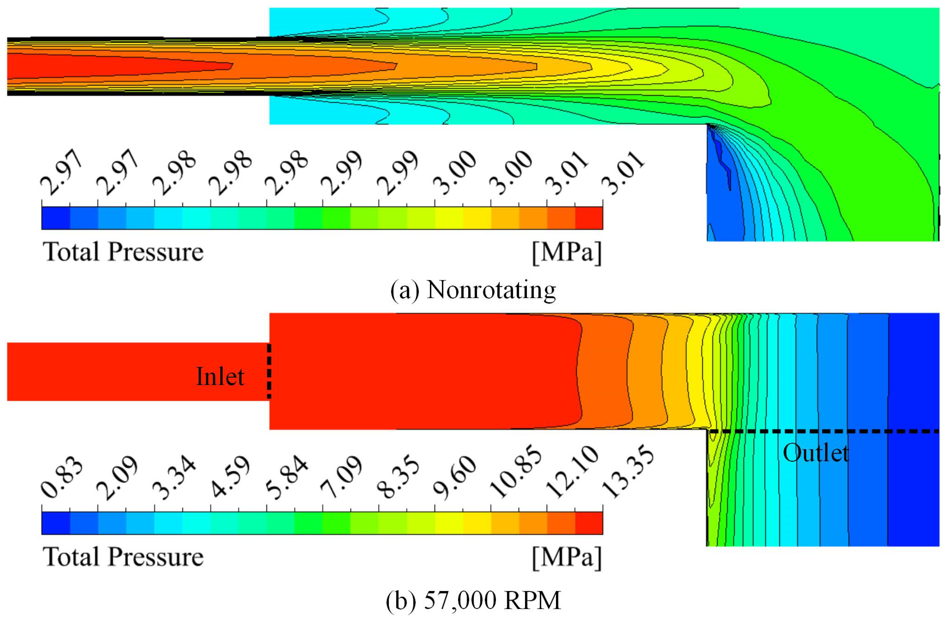
4.2. Flow Characteristics in the Confluence Cavity and the Phenomenon of the Flow Barrier
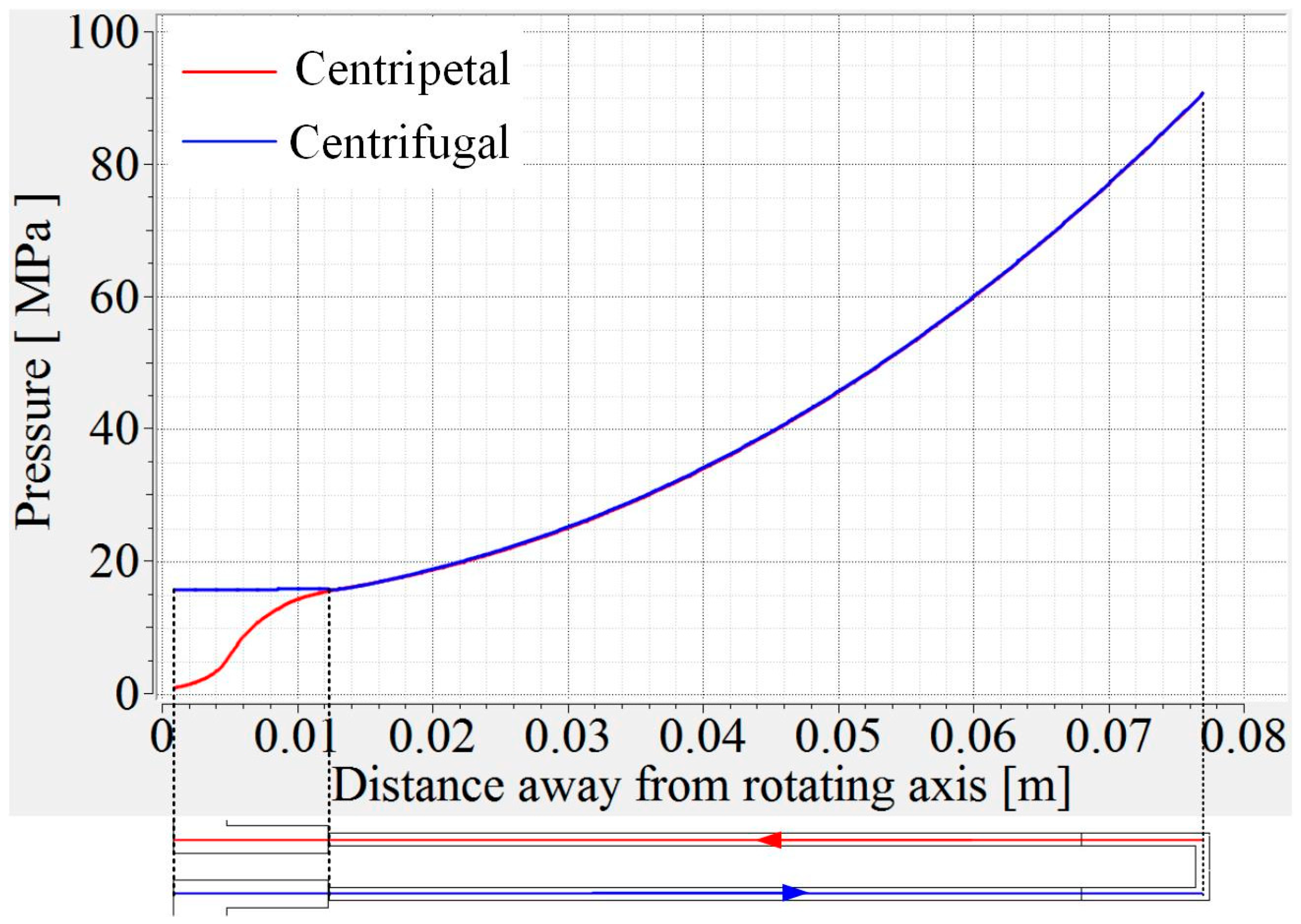
4.3. Variation of Vortexes in the Centrifugal and Centripetal Channels
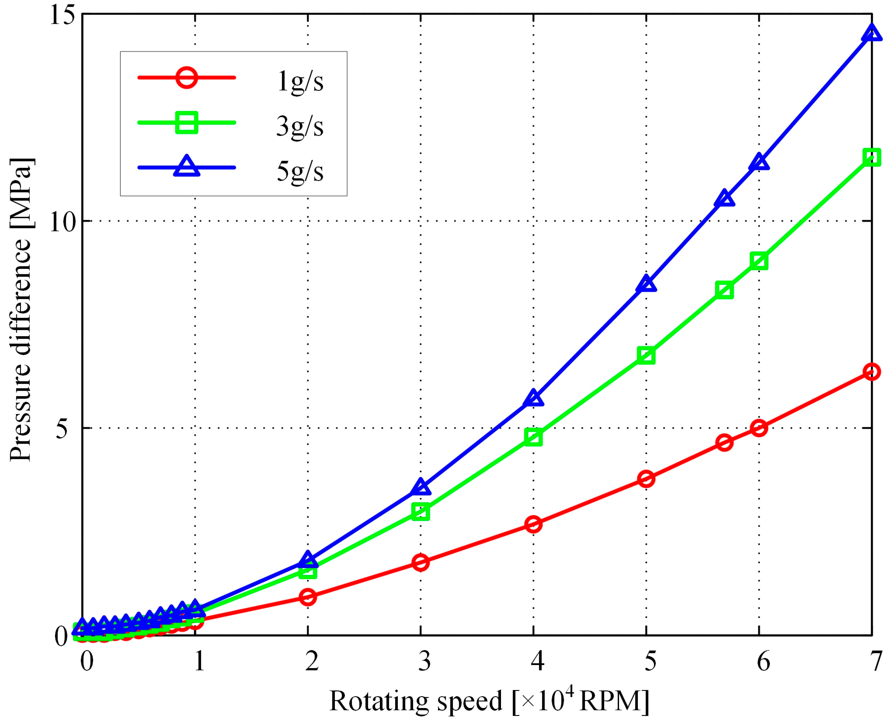
4.4. Effects of Rotation Speeds and Mass Flow Rates
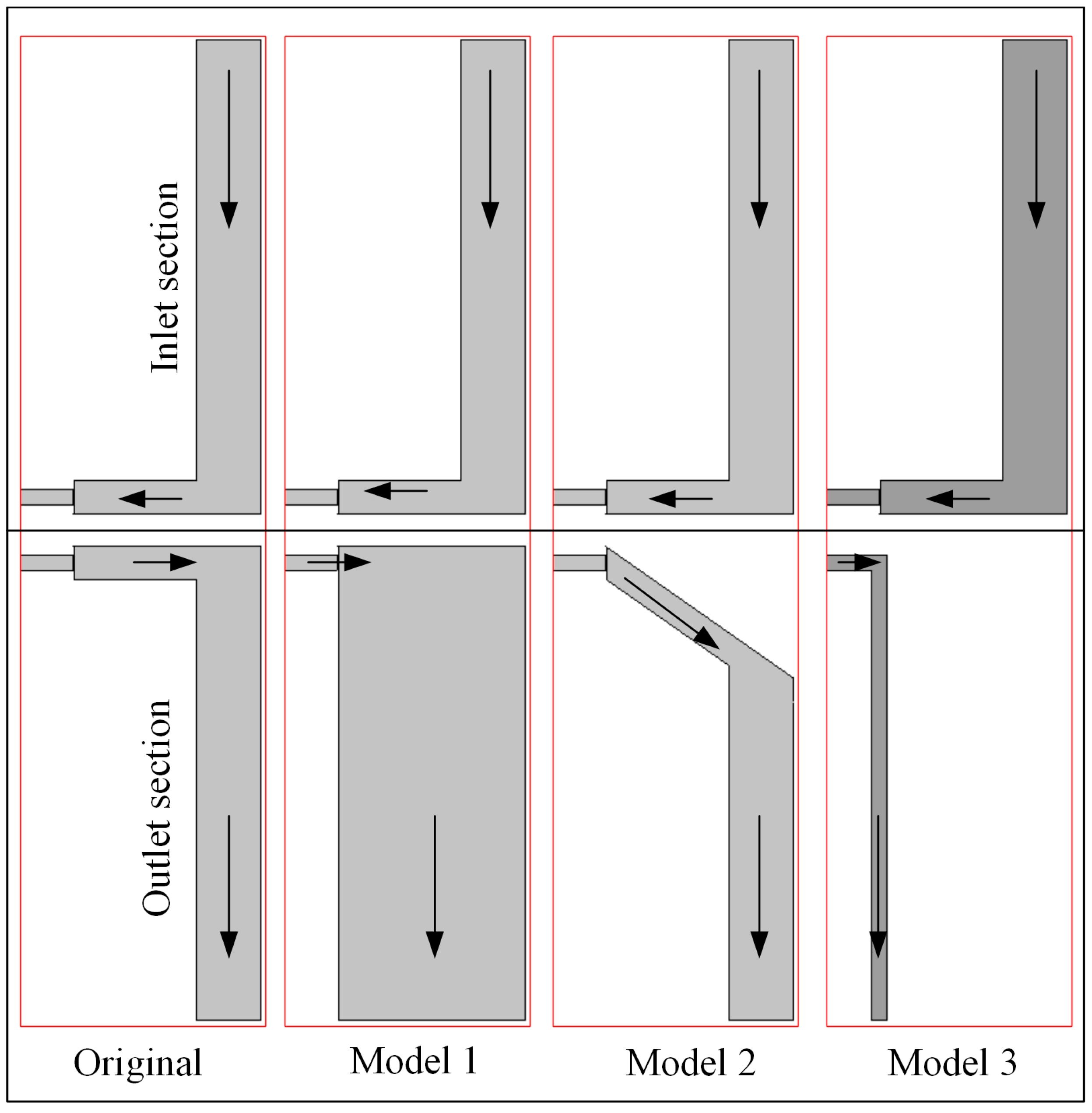
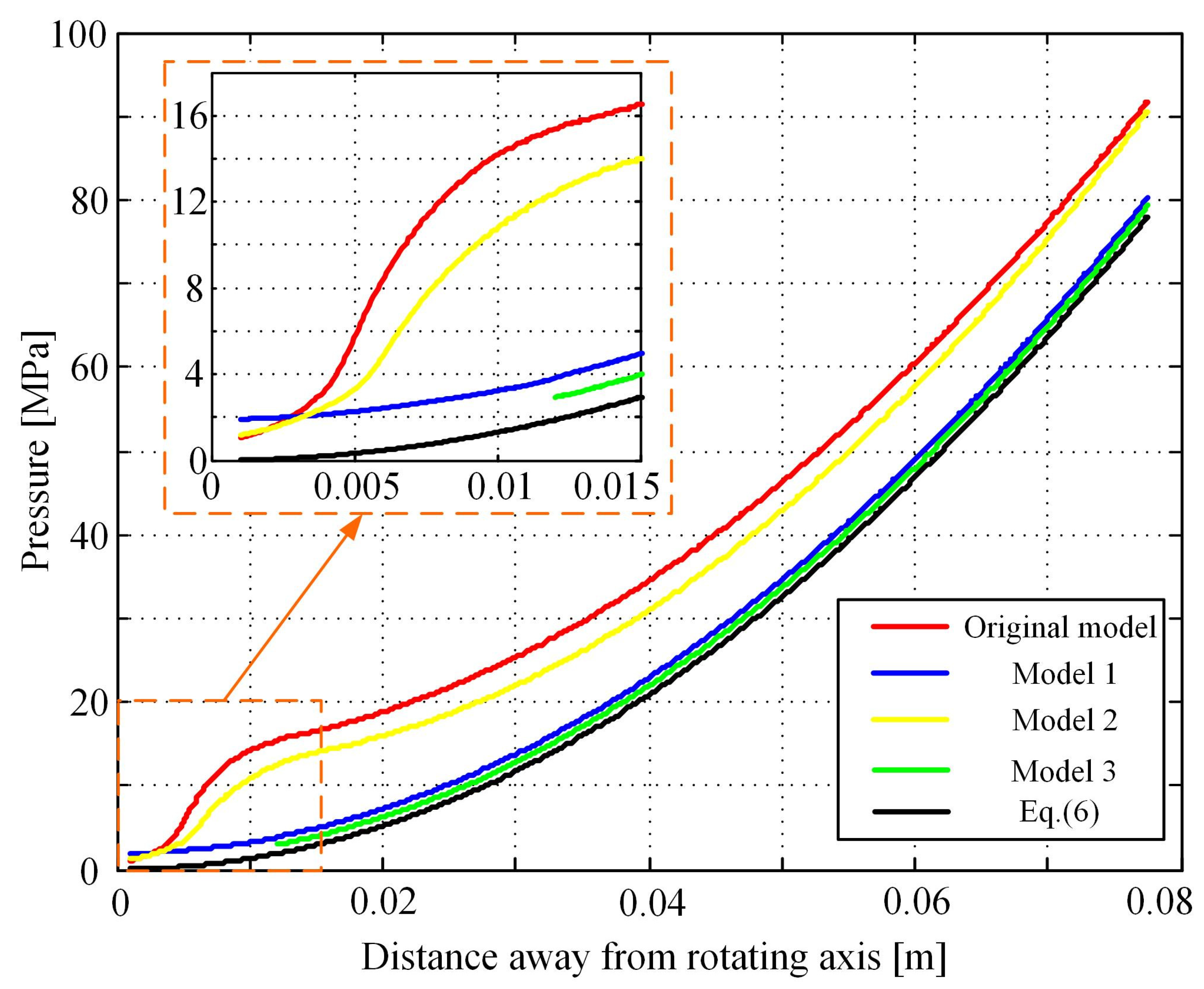
4.5. Structure Optimization for Eliminating the Flow Barrier Effect
5. Conclusions
- (1)
- The existing distributary and confluence cavities make the fuel’s rotating flow more complex and form a high-speed rotational flow. The rotational flow in the distributary cavity has a reverse rotating direction to the rotating channel, while the rotational flow in the confluence cavity has the same rotating direction as the rotating channel.
- (2)
- Under high rotation speed conditions, when the fluid flows from the confluence cavity to the axis center channel, a rotational flow with high rotational speed is formed, due to the combined effect of centrifugal force, inertia force, and the Coriolis force at the turning position. The fluid has to pass through a high rotational flow surface and overcome great flow resistance, which results in high pressure loss.
- (3)
- The pressure loss increases with the increase in rotating speed, and a high mass flow rate can result in obvious pressure loss. Modifying the outlet section structure can effectively eliminate the flow barrier effect. In this study, the optimal structure model 3 with a separated outlet channel shows the best performance with the smallest pressure loss.
Author Contributions
Funding
Data Availability Statement
Acknowledgments
Conflicts of Interest
Nomenclature
| d | hydraulic diameter [mm] |
| n | rotating speed [RPM] |
| p | pressure [Pa] |
| R | radial distance away from the rotating axis [m] |
| T | temperature [K] |
| Greek symbols | |
| ρ | density [kg/m3] |
| π | circular constant |
| Subscript | |
| SST | SST turbulence model |
| exp | experiment |
| Abbreviations | |
| CFD | computational fluid dynamics |
| SST | shear–stress–transport |
| LS | leading side |
| TS | trailing side |
References
- Chu, H.-C.; Chen, H.-C.; Han, J.-C. Numerical simulation of flow and heat transfer in rotating cooling passage with turning vane in hub region. J. Heat Transf. 2017, 140, 021701. [Google Scholar] [CrossRef]
- Xie, G.; Sunden, B. Conjugated analysis of heat transfer enhancement of an internal blade tip-wall with pin-fin arrays. J. Enhanc. Heat Transf. 2011, 18, 149–165. [Google Scholar] [CrossRef]
- Feng, Y.; Liu, S.; Qin, J.; Cao, Y.; Jiang, Y.; Zhang, S. Numerical study on the influence of turbulence on the pyrolysis of hydrocarbon fuel in mini-channel. Int. J. Heat Mass Transf. 2018, 119, 768–776. [Google Scholar] [CrossRef]
- Liu, S.; Feng, Y.; Cao, Y.; Gong, K.; Zhou, W.; Bao, W. Numerical simulation of supercritical catalytic steam reforming of aviation kerosene coupling with coking and heat transfer in mini-channel. Int. J. Therm. Sci. 2019, 137, 199–214. [Google Scholar] [CrossRef]
- Sun, F.; Li, Y.; Sunden, B.; Xie, G. The Behavior of Turbulent Heat Transfer Deterioration in Supercritical Hydrocarbon Fuel Flow Considering Thermal Resistance Distribution. Int. J. Therm. Sci. 2019, 141, 19–32. [Google Scholar] [CrossRef]
- Cong, T.; Zhang, R.; Wang, B.; Xiao, Y.; Gu, H. Single-phase flow in helical cruciform fuel assembly with conjugate heat transfer. Prog. Nucl. Energy 2022, 147, 104199. [Google Scholar] [CrossRef]
- Zhang, Y.; Cao, Y.; Feng, Y.; Xu, S.; Wang, J.; Qin, J. A new modeling method to estimate the heat transfer characteristics of supercritical aviation kerosene RP-3 with pyrolysis. Chem. Eng. Sci. 2023, 267, 118324. [Google Scholar] [CrossRef]
- Zhang, J.; Zhang, S.; Wang, C.; Tan, X. Recent advances in film cooling enhancement: A review. Chin. J. Aeronaut. 2020, 33, 1119–1136. [Google Scholar] [CrossRef]
- Jiang, P.; Lu, Z.; Guo, Y.; Zhu, Y. Experimental investigation of convective heat transfer of hydrocarbon fuels at supercritical pressures within rotating centrifugal channel. Appl. Therm. Eng. 2019, 147, 101–112. [Google Scholar] [CrossRef]
- Ibrahim, E.; Moawed, M.; Berbish, N.S. Heat transfer characteristics of rotating triangular thermosyphon. Heat Mass Transf. 2012, 48, 1539–1548. [Google Scholar] [CrossRef]
- Akhter, R.; Ali, M.M.; Alim, A. Magnetic field impact on double diffusive mixed convective hybrid-nanofluid flow and irreversibility in porous cavity with vertical wavy walls and rotating solid cylinder. Results Eng. 2023, 19, 101292. [Google Scholar] [CrossRef]
- Dong, M.; Huang, H. Hydrocarbon Fuel Flow and Heat Transfer Investigation in Rotating Channels. Energies 2023, 16, 5020. [Google Scholar] [CrossRef]
- Du, C.; Li, L.; Fan, X. Numerical study on vortex cooling flow and heat transfer behavior under rotating conditions. Int. J. Heat Mass Transf. 2017, 105, 638–647. [Google Scholar] [CrossRef]
- Sun, F.; Li, Y.; Manca, O.; Xie, G. An evaluation on the laminar effect of buoyancy-driven supercritical hydrocarbon fuel flow and heat transfer characteristics. Int. J. Heat Mass Transf. 2019, 142, 118414. [Google Scholar] [CrossRef]
- Nuntakulamarat, M.; Shiau, C.-C.; Han, J.-C. Heat transfer and pressure drop measurements in a high aspect ratio channel with circular pins and strip fins. J. Therm. Sci. Eng. Appl. 2020, 12, 031019. [Google Scholar] [CrossRef]
- Zhang, M.; Wang, N.; Han, J.-C. Internal heat transfer of film-cooled leading edge model with normal and tangential impinging jets. Int. J. Heat Mass Transf. 2019, 139, 193–204. [Google Scholar] [CrossRef]
- Huang, S.-C.; Wang, C.-C.; Liu, Y.-H. Heat transfer measurement in a rotating cooling channel with staggered and inline pin-fin arrays using liquid crystal and stroboscopy. Int. J. Heat Mass Transf. 2017, 115, 364–376. [Google Scholar] [CrossRef]
- Chia, K.-C.; Huang, S.-C.; Liu, Y.-H. Experimental investigation of heat transfer on the internal tip wall in a rotating two-pass rectangular channel. J. Therm. Sci. Eng. Appl. 2021, 13, 011025. [Google Scholar] [CrossRef]
- Huang, S.-C.; Liu, Y.-H. High rotation number effect on heat transfer in a leading edge cooling channel of gas turbine blades with three channel orientations. J. Therm. Sci. Eng. Appl. 2013, 5, 041003. [Google Scholar] [CrossRef]
- Lorenzon, A.; Casarsa, L. Validation of the transient liquid crystal thermography technique for heat transfer measurements on a rotating cooling passage. Energies 2020, 13, 4759. [Google Scholar] [CrossRef]
- Ekkad, S.V.; Singh, P. Detailed heat transfer measurements for rotating turbulent flows in gas turbine systems. Energies 2020, 14, 39. [Google Scholar] [CrossRef]
- Abdelmaksoud, R.; Wang, T. A Numerical investigation of air/mist cooling through a conjugate, rotating 3d gas turbine blade with internal, external, and tip cooling. J. Therm. Sci. Eng. Appl. 2021, 13, 021004. [Google Scholar] [CrossRef]
- Jiang, H.; Zhu, X.; Wang, D.; Huisman, S.G.; Sun, C. Supergravitational turbulent thermal convection. Sci. Adv. 2020, 6, eabb8676. [Google Scholar] [CrossRef] [PubMed]
- Jiang, H.; Wang, D.; Liu, S.; Sun, C. Experimental evidence for the existence of the ultimate regime in rapidly rotating turbulent thermal convection. Phys. Rev. Lett. 2022, 129, 204502. [Google Scholar] [CrossRef] [PubMed]
- Li, C.; Fang, X.; Luo, Z.; Dai, Q. Flow boiling heat transfer and pressure drop of R245fa inside horizontal 1.62 mm and 2.43 mm tubes under hypergravity. Int. J. Refrig. 2023, 148, 96–107. [Google Scholar] [CrossRef]
- Syaiful; Nabilah, H.; Utomo, M.T.S.; Suprihanto, A.; Soetanto, M.F. Numerical simulation of heat transfer enhancement from tubes surface to airflow using concave delta winglet vortex generators. Results Eng. 2022, 16, 100710. [Google Scholar] [CrossRef]
- Li, L.; Xu, P.; Li, Q.; Yin, Z.; Zheng, R.; Wu, J.; Bao, J.; Bai, W.; Qi, H.; Tan, D. Multi-field coupling particle flow dynamic behaviors of the microreactor and ultrasonic control method. Powder Technol. 2025, 454, 120731. [Google Scholar] [CrossRef]
- Zheng, G.; Xu, P.; Wang, T.; Yan, Q. Study on the bubble collapse characteristics and heat transfer mechanism of the microchannel reactor. Processes 2025, 13, 281. [Google Scholar] [CrossRef]
- Dong, A.; Yan, P.; Qian, X.; Han, W.; Wang, Q. Rotation effect on flow and heat transfer for high-temperature rotor blade in a heavy gas turbine. J. Therm. Sci. 2021, 30, 707–715. [Google Scholar] [CrossRef]
- Khattak, S.; Ahmed, M.; Abrar, M.N.; Uddin, S.; Sagheer, M.; Javeed, M.F. Numerical simulation of Cattaneo–Christov heat flux model in a porous media past a stretching sheet. Waves Random Complex Media 2025, 35, 1230–1249. [Google Scholar] [CrossRef]
- Shah, S.; Abrar, M.N.; Akhtar, K.; Khan, A.; Abdeljawad, T. Entropy formation analysis for magnetized UCM fluid over an exponentially stretching surface with PST and PSHF wall conditions. AIMS Math. 2023, 8, 11666–11683. [Google Scholar] [CrossRef]
- Zhang, Y.; Li, Z.; Li, L.; Wang, C.; Wu, J.; Xie, Y.; Yin, Z.; Tan, D. Deposition mechanism of microscopic impacting droplets on flexible porous substrates. Int. J. Mech. Sci. 2025, 288, 110050. [Google Scholar] [CrossRef]
- Tan, Y.; Ni, Y.; Xu, W.; Xie, Y.; Li, L.; Tan, D. Key technologies and development trends of the soft abrasive flow finishing method. J. Zhejiang Univ. A 2023, 24, 1043–1064. [Google Scholar] [CrossRef]
- Abrar, M.N.; Uddin, S.; Akhtar, K. Rheology of suspended hybrid nanoparticles in micro-rotating tangent hyperbolic fluid over a stretching surface. J. Central South Univ. 2023, 30, 1231–1245. [Google Scholar] [CrossRef]
- Khan, A.S.; Abrar, M.N.; Uddin, S.; Awais, M.; Usman, I. Entropy generation due to micro-rotating Casson’s nanofluid flow over a nonlinear stretching plate: Numerical treatment. Waves Random Complex Media 2022, 35, 1–16. [Google Scholar] [CrossRef]
- Sun, H.; Qin, J.; Huang, H.; Yan, P. Numerical simulation of flow and heat transfer in a square rotating u-duct using hydrocarbon fuel. J. Heat Transf. 2019, 141, 031701. [Google Scholar] [CrossRef]
- Sun, H.; Qin, J.; Li, H.; Huang, H.; Yan, P. Research of a combined power and cooling system based on fuel rotating cooling air turbine and organic Rankine cycle on hypersonic aircraft. Energy 2019, 189, 116183. [Google Scholar] [CrossRef]
- Sun, H.; Qin, J.; Huang, H.; Yan, P. Investigation of hydrocarbon fuel rotating flow considering the variation of physical properties. Int. J. Heat Mass Transf. 2019, 142, 118372. [Google Scholar] [CrossRef]
- Sun, H.; Gao, P.; Li, H.; Hou, F.; Yuan, P. Investigation of water phase change rotating cooling for high temperature turbine. Results Eng. 2024, 21, 101707. [Google Scholar] [CrossRef]
- Lemmon, E.W.; Bell, I.H.; Huber, M.L.; McLinden, M.O. NIST Standard Reference Database 23: Reference Fluid Thermodynamic and Transport Properties-REFPROP, Version 10.0; Standard Reference Data Program; National Institute of Standards and Technology: Gaithersburg, MD, USA, 2018. [Google Scholar]


| Parameter | Decane |
|---|---|
| Mole mass [g/mol] | 142 |
| Density [kg/m3] | 730.0 |
| Specific heat capacity [kJ/(kg·K)] | 2.39 |
| Thermal conductivity [W/(m·K)] | 0.14 |
| Dynamic viscosity [Pa·s] | 7.67 × 10⁻⁴ |
| Nodes | Position 1 | Position 2 | Position 3 | |
|---|---|---|---|---|
| Temperature [K] | Pressure [MPa] | Wall Heat Transfer Coefficient [W/(m2·K)] | Velocity [m/s] | |
| 680,952 | 359.48 | 91.00 | 70,499 | 52.73 |
| 820,232 | 359.65 | 90.78 | 70,507 | 52.85 |
| 910,232 | 359.66 | 90.79 | 70,504 | 52.86 |
| 1,000,232 | 359.63 | 90.78 | 70,502 | 52.85 |
| 1,116,232 | 359.63 | 90.79 | 70,499 | 52.86 |
| 1,399,272 | 359.68 | 90.48 | 70,496 | 52.95 |
| 1,525,272 | 359.72 | 90.47 | 70,516 | 52.95 |
| Parameter | Original | Model 1 | Model 2 | Model 3 |
|---|---|---|---|---|
| Inlet total pressure, MPa | 15.54 | 4.265 | 14.39 | 2.991 |
| Inlet static pressure, MPa | 15.71 | 4.261 | 14.55 | 3.156 |
| Outlet total pressure, MPa | 5.05 | 1.914 | 5.008 | 1.005 |
| Outlet static pressure, MPa | 4.29 | 3.859 | 4.245 | 3.056 |
| Total pressure loss, MPa | 10.49 | 2.351 | 9.382 | 1.986 |
| Static pressure loss, MPa | 11.42 | 0.402 | 10.305 | 0.1 |
Disclaimer/Publisher’s Note: The statements, opinions and data contained in all publications are solely those of the individual author(s) and contributor(s) and not of MDPI and/or the editor(s). MDPI and/or the editor(s) disclaim responsibility for any injury to people or property resulting from any ideas, methods, instructions or products referred to in the content. |
© 2025 by the authors. Licensee MDPI, Basel, Switzerland. This article is an open access article distributed under the terms and conditions of the Creative Commons Attribution (CC BY) license (https://creativecommons.org/licenses/by/4.0/).
Share and Cite
Zheng, K.; Ma, H.; Sun, H.; Qin, J. Investigation of Flow Characteristics in Rotating Distributary and Confluence Cavities. Energies 2025, 18, 1287. https://doi.org/10.3390/en18051287
Zheng K, Ma H, Sun H, Qin J. Investigation of Flow Characteristics in Rotating Distributary and Confluence Cavities. Energies. 2025; 18(5):1287. https://doi.org/10.3390/en18051287
Chicago/Turabian StyleZheng, Kuan, Huan Ma, Hongchuang Sun, and Jiang Qin. 2025. "Investigation of Flow Characteristics in Rotating Distributary and Confluence Cavities" Energies 18, no. 5: 1287. https://doi.org/10.3390/en18051287
APA StyleZheng, K., Ma, H., Sun, H., & Qin, J. (2025). Investigation of Flow Characteristics in Rotating Distributary and Confluence Cavities. Energies, 18(5), 1287. https://doi.org/10.3390/en18051287