Article

A Modeling Technique for High-Efficiency Battery Packs in Battery-Powered Railway System

Department of Electronic Engineering, The Korea National University of Transportation, Chungju 27469, Republic of Korea
*
Author to whom correspondence should be addressed.
Energies 2025, 18(5), 1272; https://doi.org/10.3390/en18051272
Submission received: 31 January 2025 / Revised: 28 February 2025 / Accepted: 28 February 2025 / Published: 5 March 2025
(This article belongs to the Special Issue Advances in Electrical Power System Quality)

Abstract

Battery modules in eco-friendly mobility are composed of series and parallel connections of multiple lithium-ion battery cells. As the number of lithium-ion cells in the battery module increases, the cell connection configuration becomes a critical factor affecting the module’s usable capacity efficiency. Therefore, careful consideration of this factor is essential in battery module design. Various design elements have been studied to optimize the performance of battery modules. Among these elements, the method of terminal connection affects the distribution of resistance components in each cell, causing DOD (Depth of Discharge) variation. Previous research has focused on determining the optimal terminal placement and cell connection method to minimize DOD variation between cells. However, these studies did not consider temperature effects. Since temperature acts as a major variable affecting the DOD of each cell, comprehensive research that includes this factor is necessary. This research performed 3D thermal flow analysis using Ansys Fluent 2024 R2 and validated the simulation environment by comparing actual experimental and simulation results for a single cell. Based on the validated simulation environment, this research analyzed the impact of temperature distribution on cell performance in a 4S3P module and proposed a method of terminal connection, which achieved a 70% reduction in SOC deviation compared to conventional methods. Additionally, this research suggests that when the module configuration changes, a new design approach specific to that configuration is necessary to minimize SOC deviation.

1. Introduction

As climate change emerges as a pressing global concern, nations worldwide are implementing ambitious carbon reduction [1]. In response to these environmental initiatives, the transportation industry is undergoing a significant transformation, shifting from traditional fossil fuel-powered systems to lithium-ion battery technology [2,3,4,5]. Railway vehicles, traditionally recognized for their eco-friendly electric traction systems, have begun incorporating a Hybrid Energy Storage System (HESS) combining fuel cells and batteries or a standalone battery-based Energy Storage System (ESS) [6,7,8]. These systems are expanded to module and pack units to provide sufficient traction power for the vehicle’s operational requirements [9]. The expansion of battery modules introduces challenges related to parasitic resistance elements, which affect the current density distribution of individual cells as module size increases. These effects manifest as variations in Depth of Discharge (DOD) between cells [10,11], leading to accelerated degradation of individual cells and shortened battery module lifecycle [12,13]. Consequently, minimizing DOD variation has become a critical consideration in battery module design. Previous research has explored various approaches to address this issue through optimization of cell interconnection topology and methods of terminal connection. Wang et al. [14] demonstrated through simulation analysis that resistance variations induced by the method of terminal connection significantly affect individual cell current density distribution. Zhang, H et al. [15] established that current density imbalance becomes severe when interconnection resistance exceeds 1% of the cell’s internal resistance in parallel configurations. Kim et al. [16] demonstrated that a topology method interconnecting all cells within the battery module reduces DOD variation between cells. Yang et al. [17] configured a simulation environment with two cells having similar internal resistance to emulate an EV battery pack. Through this, they analyzed the effect of temperature differences between cells on performance in actual electric vehicle driving environments. Specifically, they observed the capacity reduction due to changes in internal resistance between cells in series and parallel connections by setting the temperature difference between the two cells from 10 to 20 degrees. However, this research has limitations in that it simplifies the actual EV battery pack into two cells with similar internal resistance and that each cell is exposed to different thermal flow environments. Cell internal resistance exhibits temperature dependence [18,19], and the thermal gradient between central and peripheral cells creates additional variations in current density distribution [20,21]. This thermal behavior becomes particularly significant in high-power applications like railway vehicles, where thermal management system requirements show greater complexity [22,23]. This research investigates cell performance characteristics by analyzing thermal gradient effects and methods of terminal connection. Through three-dimensional computational fluid dynamics analysis using Ansys Fluent 2024 R2, the thermal behavior of various module configurations has been simulated based on different methods of terminal connection. This analysis has led to the development of an optimal module configuration method that minimizes inter-cell performance variations.

2. Theoretical Analysis and Design Considerations

This research employed a 4S-3P module configuration as the basic module structure for simulating railway vehicle battery modules, referencing the final report of Korea’s Catenary-Free Low Floor Tram commercialization project [24] (p. 219).

2.1. Analysis of Methods for Terminal Connection

The module terminals function as power delivery interfaces to the load, and the method of terminal connection significantly influences the DOD variation between cells. This consideration becomes particularly critical as high DOD accelerates battery degradation, making the method of terminal connection a fundamental factor in module design. To analyze how different methods of terminal connection affect cell-to-cell DOD differences, this section examines three widely adopted connection methods: single connection method, center connection method, and diagonal connection method [15,25,26].

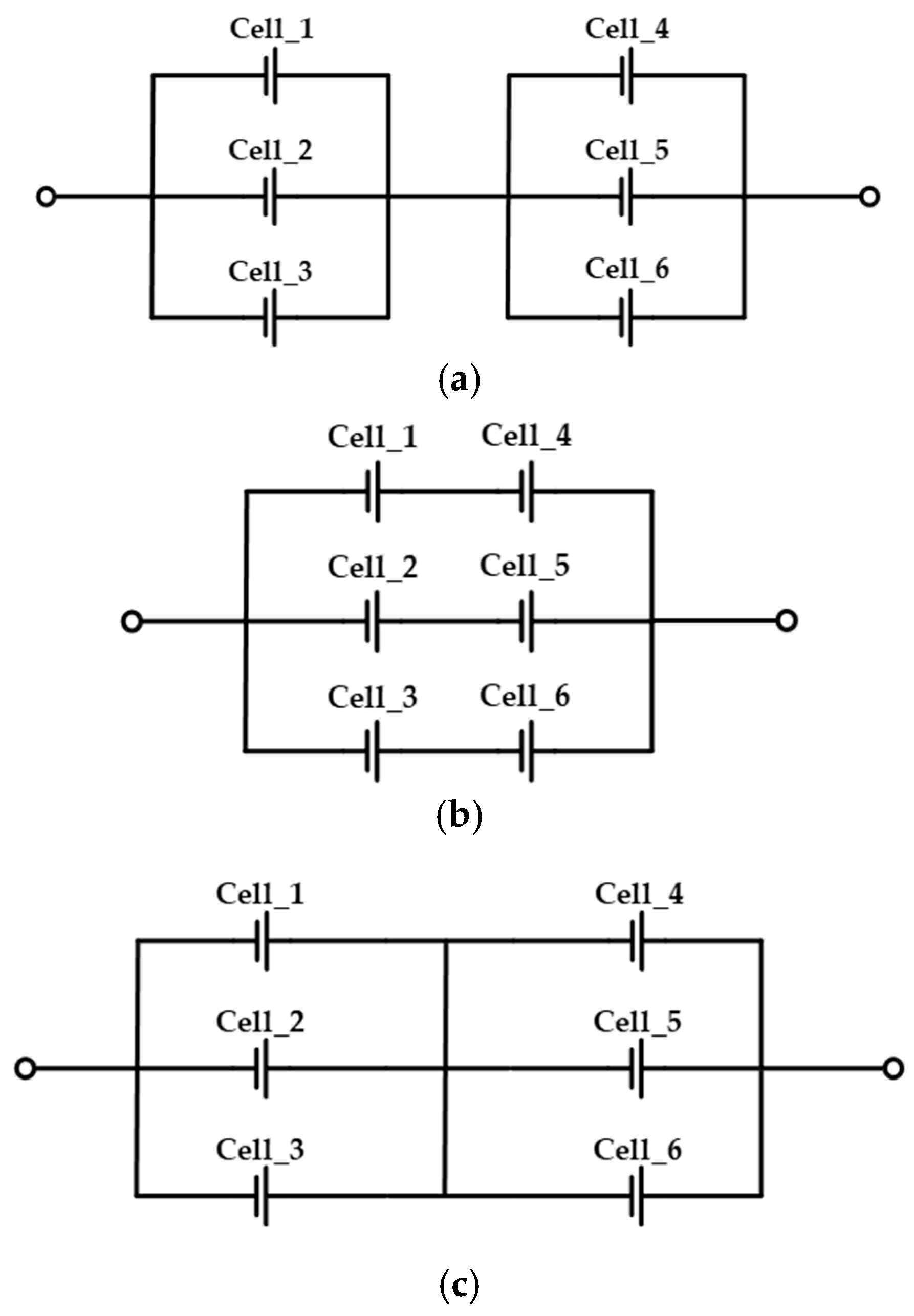
2.1.1. Single Connection Method

The single connection method places terminals exclusively at cells located at both ends of the upper or lower part of the module. Figure 1 illustrates the 4S-3P configuration through both electrical circuits and 3D modeling representations. The current output from each series string can be expressed by Equations (1)–(3), where V denotes the cell voltage, and Rc represents the resistance of the connecting plate between cells. Nickel plates were used for all connecting plates (Rc-Rc22), and since their resistance shows minimal variation with temperature, we assumed a constant Rc value for simplification.
I s t r 1 = V 7 · R c
I s t r 2 = V 5 · R c
I s t r 3 = V 3 · R c
In the single connection method, current distribution becomes imbalanced based on proximity to the terminals. Specifically, the first series string carries V/(3Rc), the second series string carries V/(5Rc), and the third series string carries V/(7Rc) of current. This exhibits decreasing current distribution with increasing distance from the terminals. This variation occurs because the resistance components of the interconnection plates accumulate differently for each series string relative to the terminal. Consequently, the first series string, which outputs relatively higher current, exhibits higher DOD compared to other series strings. Over time, this DOD variation between cells intensifies, leading to decreased module efficiency.

2.1.2. Center Connection Method

The center connection method places terminals at cells located in the center of the module while connecting to cells at both ends. Figure 2 represents the 4S-3P configuration through both an electrical circuit and a 3D modeling illustration, where the current output from each series string can be expressed by Equations (4) and (5), where V denotes the cell voltage, and Rc represents the resistance of the connecting plate between cells. Nickel plates were used for all connecting plates (Rc-Rc22), and since their resistance shows minimal variation with temperature, we assumed a constant Rc value for simplification.
I s t r 1 = I s t r 3 = V 5 · R c
I s t r 2 = V 3 · R c
Similar to the single connection method, the center connection method exhibits current distribution patterns influenced by proximity to terminals. The second series string, positioned in the center of the module, carries V/(3Rc) of current, while the first and third series strings at both ends carry V/(5Rc) of current. This demonstrates the same characteristic where the current magnitude decreases as the distance from the terminal increases. The key distinction from the single connection method lies in the formation of symmetrical current distribution, where the first and third series strings carry identical currents due to the direct terminal connection to the second series string. Due to the influence of interconnection plate resistance components added from the module terminals to the batteries, the second series string, which outputs a relatively higher current, shows a higher DOD compared to other series strings. As time progresses, this DOD variation between cells intensifies, resulting in decreased module efficiency.

2.1.3. Diagonal Connection Method

The diagonal connection method places terminals by cross-connecting the upper and lower ends of the module. Figure 3 presents the 4S-3P configuration through both electrical circuit and 3D model illustrations, where the current output from each series string can be expressed by Equation (6), where V denotes the cell voltage, and Rc represents the resistance of the connecting plate between cells. Nickel plates were used for all connecting plates (Rc-Rc22), and since their resistance shows minimal variation with temperature, we assumed a constant Rc value for simplification.
I s t r 1 = I s t r 2 = I s t r 3 = V 5 · R c
Unlike the two connection methods discussed previously, the diagonal connection method demonstrates uniform current distribution across all series strings, with each carrying V/(5Rc) of current. This uniform distribution occurs because all cells maintain identical interconnection plate resistance paths to the terminals. Consequently, the diagonal connection method exhibits minimal DOD variation between cells compared to both single connection and center connection methods.

2.2. Analysis of Temperature Effect

The internal resistance of battery cells demonstrates a close relationship with temperature, and the electrochemical reactions within the battery can be explained by the Arrhenius equation, shown in Equation (7).
k = A · e E a R · T
where k represents the reaction rate constant, A is the frequency factor, Ea denotes the activation energy, R is the gas constant, and T represents the absolute temperature [27]. According to Equation (7), as the ambient temperature of the battery increases, the rate of chemical reactions within the battery accelerates, enhancing the mobility (movement capability) of lithium ions. This enhanced mobility leads to decreased internal resistance of the battery cells [28]. While the current distribution patterns analyzed earlier based on terminal placement were derived assuming uniform internal resistance across all cells, actual operating conditions present a more complex scenario. Each cell experiences different temperature conditions depending on its position within the module, leading to variations in internal resistance values. These position-dependent temperature variations cause DOD differences even in the diagonal connection method, which theoretically should provide uniform current distribution. The 4S-3P module configuration inherently creates distinct temperature gradients due to its cell arrangement characteristics. Cells positioned in the center are exposed to relatively higher temperature environments, while cells at the periphery experience lower temperatures. This temperature distribution difference results in lower internal resistance in central cells, allowing higher current flow through these cells. Consequently, central cells discharge at higher DOD compared to peripheral cells. Therefore, when designing battery modules for railway vehicles, it is essential to consider the combined effects of temperature-induced internal resistance variations and the method of terminal connection on cell-to-cell DOD variations.

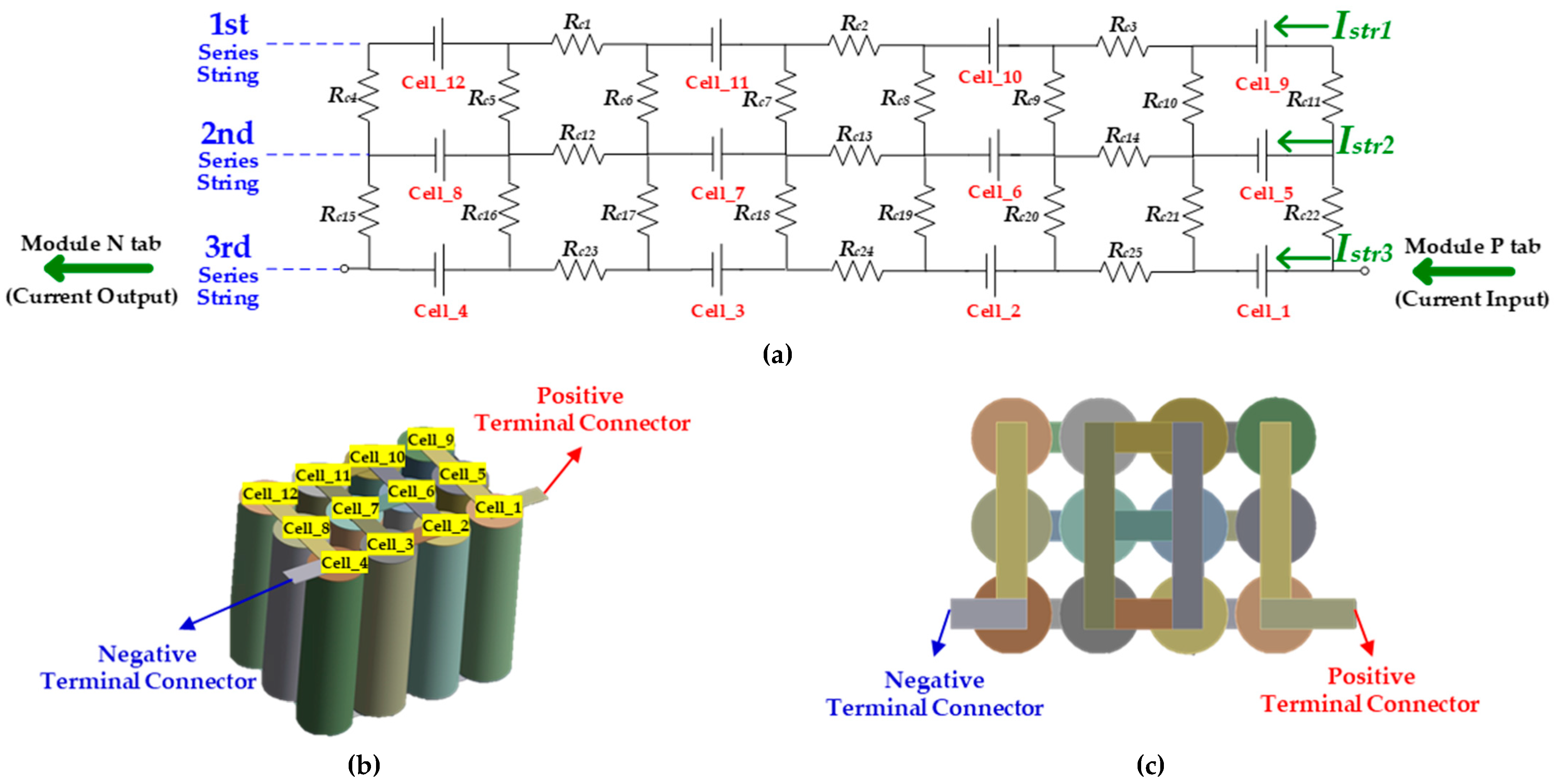
2.3. Cell to Cell Connection Topology

The topology of cell connections in battery module design significantly impacts DOD variation and cell balancing characteristics. Cell balancing, performed during railway vehicle non-operating periods, serves as a mechanism to reduce DOD variations that develop during operation. Figure 4 illustrates three primary cell connection topologies [29,30].
Configuration (a) shows parallel strings connected in series. While cell balancing within each parallel string helps resolve DOD variations, this method has limitations as balancing between parallel strings does not occur, leading to persistent DOD differences between strings. Configuration (b) shows a series of strings connected in parallel. This arrangement allows cell balancing between series strings, helping to resolve DOD variations between strings. However, it cannot address DOD variations between individual cells within each series string. Configuration (c) shows a full cell interconnection topology. This configuration offers structural advantages by connecting all cells to each other, enabling effective resolution of DOD variations across the entire module. It particularly excels at reducing DOD variations that develop during operation. Therefore, optimizing battery module performance requires comprehensive consideration of multiple factors: method of terminal connection, temperature distribution, and connection topology characteristics.

2.4. Proposed Module Configuration

Based on the analysis presented in Section 2, this research proposes an optimized battery module configuration that comprehensively considers the method of terminal connection, temperature distribution within the module, and cell-to-cell connection topology. The primary sources of DOD variation during operation primarily result from the method of terminal connection and temperature distribution within the module. Since temperature distribution is an inherent phenomenon, this research proposes a method that counterbalances temperature effects through the strategic method of terminal connection. Figure 5 shows the electrical circuit and 3D modeling representations of the proposed configuration for a 4S-3P module. The proposed configuration builds upon the center connection method but optimizes the series connecting of parallel strings to minimize current distribution in the central cells, which experience relatively higher temperatures. The output current for each cell in the proposed configuration can be expressed by Equations (8) and (9), where V denotes the cell voltage, and Rc represents the resistance of the connecting plate between cells. Nickel plates were used for all connecting plates (Rc-Rc22), and since their resistance shows minimal variation with temperature, we assumed a constant Rc value for simplification.
I c e l l 7 = I c e l l 6 = V 7 · R c
I o t h e r = V 5 · R c
The key innovation in this configuration lies in the differentiated current distribution of cell6 and cell7 located in the center. Through the modified method of terminal connection and cell connection topology, these cells carry a relatively lower current of V/(7Rc). While centrally located cells experience higher temperatures, leading to decreased internal resistance Rc in Equation (8), peripheral cells encounter lower temperatures, resulting in increased internal resistance Rc in Equation (9). Consequently, the current distribution determined by the method of terminal connection and cell connection topology counterbalances the changes in internal resistance caused by temperature effects, resulting in a more uniform overall DOD distribution.

3. Experimental Methods and Results

In this chapter, temperature effects were incorporated using Ansys Fluent 2024 R2, a three-dimensional heat flow simulation tool. The performance of the proposed connection method was then validated through comparisons with a conventional method of terminal connection.

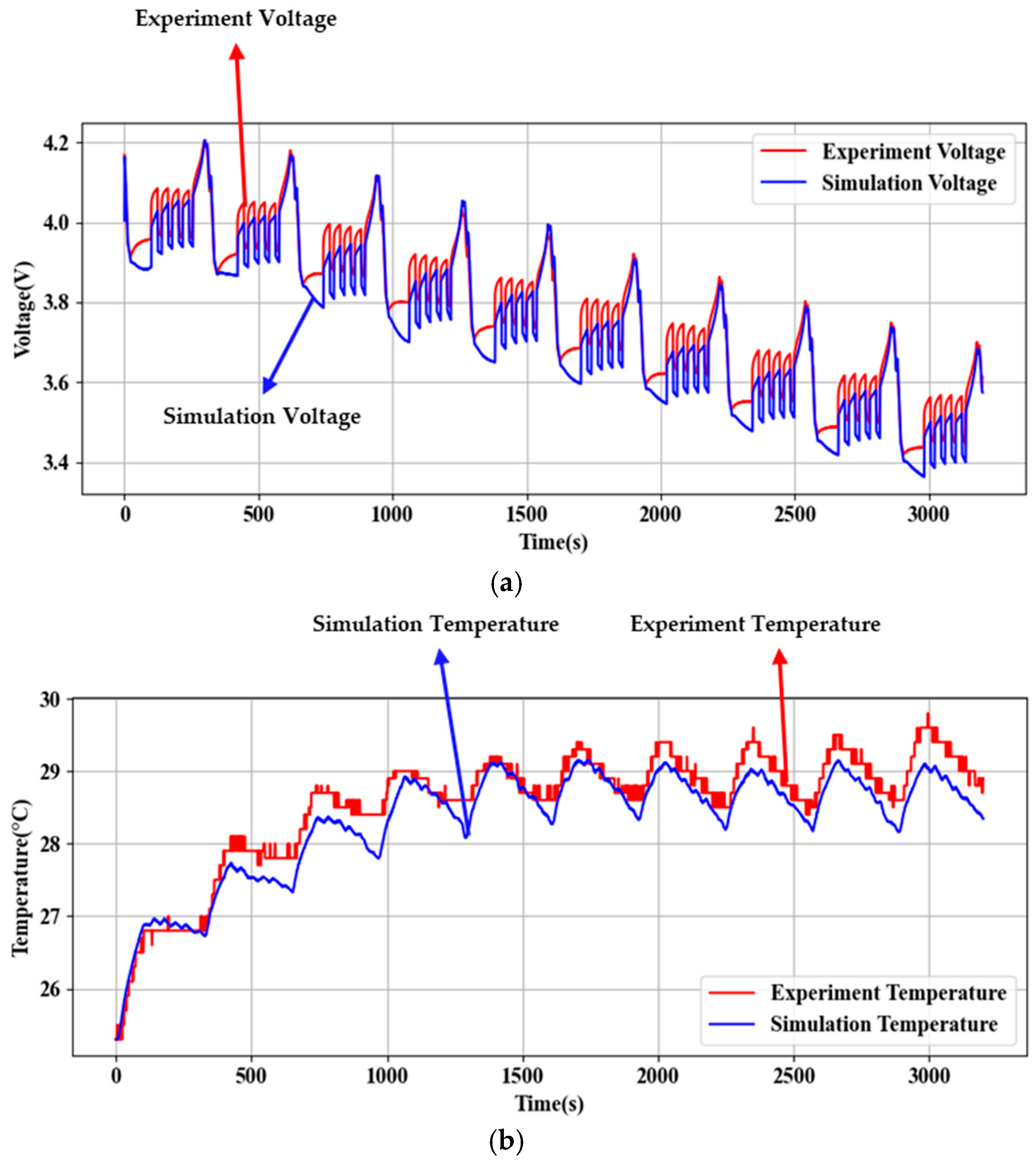
3.1. Simulation Environment Setup and Validation

The simulation environment was established to closely resemble experimental conditions, with initial simulations conducted using a single cell as a baseline. The accuracy of the simulation environment was verified by comparing surface temperature and voltage measurements from actual experiments with simulation data. The INR21700-40T cell (Samsung SDI, Yongin, Republic of Korea) was utilized for both simulation and experimental testing. The physical properties of this battery, referenced from previous research, are summarized in Table 1 [31]. The heat source in the battery for this research is primarily attributed to Joule heating (P). Specifically, the heat source is calculated based on the input/output current (I) of the battery and the internal resistance (R), which varies according to the state of charge (SOC), as expressed by the following equation:
P = I 2 · R
Since cylindrical batteries are used in this research, a single heat transfer coefficient was applied. The experimental setup maintained a constant cell ambient temperature of 25 °C through a chamber, with current profiles applied via a battery cycler. The measured surface temperature and voltage of the battery were collected as reference data for simulation validation. A railway vehicle driving profile, representing battery demands during station-to-station operation, was repeated 10 times. Table 2 presents the experimental equipment configuration, while Figure 6 illustrates one cycle of the railway vehicle driving profile.
Figure 7 shows the overall experimental setup. The comparison between experimental and simulation results for voltage and surface temperature is presented in Figure 8. The analysis revealed maximum differences of 0.17 V for voltage and 0.74 °C for surface temperature between simulated and experimental measurements. These minimal differences confirm that the constructed simulation environment effectively replicates experimental conditions. These differences represent maximum errors of 5% for voltage and 3% for temperature. Despite these discrepancies, the simulation results consistently reflect the changing patterns observed in the experimental data, and this consistent trend matching sufficiently demonstrates the reliability of the simulation model.

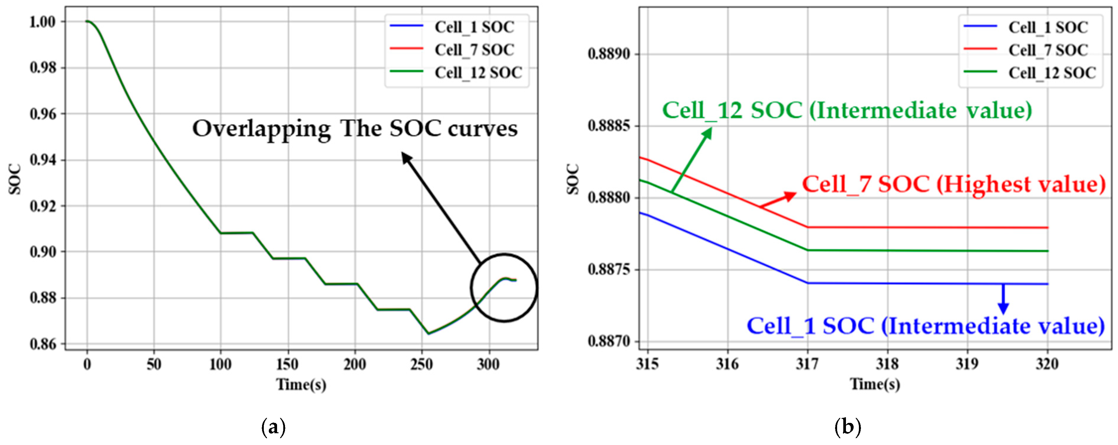
3.2. Validation of Proposed Model

The validated single-cell simulation model from Section 3.1 was expanded to a 4S-3P configuration to analyze the impact of terminal connection methods and temperature distribution on cell-to-cell depth of discharge (DOD) variations. To quantitatively verify the effects of the battery module terminal connection methods and temperature distribution previously analyzed, an indirect analysis of the State of Charge (SOC) was performed. In a simulation environment where direct DOD measurement is challenging, SOC serves as a representative indicator for evaluating energy consumption and performance imbalances between cells. The SOC of each cell was calculated using the Coulomb counting method. The coulomb counting method is as follows:
S O C ( t ) = S O C ( 0 ) + 1 Q n 0 t I ( t ) · d t
where
SOC(0): Initial SOC value (set to 1);
I(t): Current value over time [A];
Qn: Nominal capacity of the battery [Ah];
t: Sampling time [h].
A single railway vehicle driving profile cycle was applied to observe SOC changes in cells located at central and peripheral positions. Specifically, Cell_1 and Cell_12 were selected as representative values for peripheral cells, while Cell_7 represented central cells.
Figure 9 illustrates the SOC changes for Cell_1, Cell_7, and Cell_12 across different connection methods. Figure 9a,b shows the single connection methods, Figure 9c,d the center connection methods, Figure 9e,f the diagonal connection methods, and Figure 9g,h the proposed connection methods. The enlarged graphs (Figure 9b,d,f,h) enable a more precise observation of subtle SOC differences between cells. The simulation results revealed the SOC deviations for each battery module method of terminal connection, as summarized in Table 3. The maximum SOC deviation was calculated at the end of the railway vehicle driving profile by comparing the highest and lowest SOC values among all cells. These maximum SOC deviations were 0.00039 for the single connection method, 0.00014 for the center connection method, 0.00146 for the diagonal connection method, and 0.00004 for the proposed connection method. When compared to the diagonal connection method, which showed the largest deviation among conventional approaches, the proposed method achieved approximately 70% reduction in maximum SOC deviation.

4. Conclusions

The simulation results from this research present a perspective different from that of previous research regarding battery module design for railway vehicle applications. While previous studies analyzed the diagonal connection method, one of the terminal connection methods, as theoretically providing uniform current distribution, the temperature-considered analysis in this research reveals that this method actually exhibits greater DOD variations compared to other connection methods. This finding challenges the conventional understanding of optimal battery module configuration and emphasizes the critical importance of considering temperature effects in design decisions. The connection method proposed in this research has been improved to allow lower current flow through the central cells experiencing higher temperatures through modifications in both terminal connection methods and cell-to-cell connection topology, demonstrating minimal DOD variations when compared to the three conventional methods. This improvement stems from the complementary interaction between current distribution control in central cells and temperature effects. Specifically, the lower current distribution in central cells forms a complementary relationship with the decreased internal resistance caused by temperature rise, contributing to the minimization of cell-to-cell DOD variations. Simulation results demonstrate that the proposed connection method shows a 70% improvement in DOD variation compared to the center connection method, which had previously shown the best performance among conventional terminal connection methods. However, the proposed module configuration exhibits certain limitations, as it is specifically optimized for the 4S-3P structure. When the module configuration changes, such as to a 12S-2P structure, the temperature distribution characteristics and effects of terminal connection methods require comprehensive reanalysis. This suggests a need for further research to develop a systematic and generalized design methodology applicable to various module configurations. Despite these limitations, this research makes significant contributions to the field of railway vehicle battery module design. The findings provide practical guidelines for optimizing 4S-3P module configurations, particularly in applications where temperature variations significantly impact battery performance. The proposed method’s ability to counterbalance temperature-induced effects through strategic terminal connection methods and cell interconnection topology offers a novel approach to battery module design, establishing a foundation for future research in this domain.

Author Contributions

Conceptualization, J.-U.S.; methodology, J.-U.S.; software, S.-W.K.; validation, I.-H.C.; formal analysis, J.-U.S.; investigation, J.-U.S.; resources, I.-H.C.; data curation, S.-W.K.; writing—original draft preparation, J.-U.S.; writing—review and editing, I.-H.C.; visualization, S.-W.K.; supervision, I.-H.C.; project administration, I.-H.C.; funding acquisition, I.-H.C. All authors have read and agreed to the published version of the manuscript.

Funding

This work was supported by the Korea Institute of Energy Technology Evaluation and Planning (KETEP) and the Ministry of Trade, Industry & Energy (MOTIE) of the Republic of Korea (No. RS-2024-00394769). This work was supported by the National Research Foundation of Korea (NRF) grant funded by The Korean government (MSIT) (No. RS-2024-00210755).

Data Availability Statement

The original contributions presented in this study are included in the article. Further inquiries can be directed to the corresponding author(s).

Conflicts of Interest

The authors declare no conflicts of interest.

References

  1. Cheng, V.S.; Li, G.-J. Policy on Carbon Reduction. In Decarbonization of Cities in Asia; Springer: Singapore, 2023; pp. 49–96. [Google Scholar] [CrossRef]
  2. Li, Y.; Chen, M. Lithium-Ion Batteries. In Towards Next Generation Energy Storage Technologies; Wiley: Hoboken, NJ, USA, 2024; pp. 31–54. [Google Scholar] [CrossRef]
  3. Tosun, E.; Keyinci, S.; Yakaryılmaz, A.C.; Yıldızhan, Ş.; Özcanlı, M. Evaluation of Lithium-Ion Batteries in Electric Vehicles. Int. J. Automot. Sci. Technol. 2024, 8, 332–340. [Google Scholar] [CrossRef]
  4. Lal, A.; You, F. Will Reshoring Manufacturing of Advanced Electric Vehicle Battery Support Renewable Energy Transition and Climate Targets? Sci. Adv. 2023, 9, adg6740. [Google Scholar] [CrossRef] [PubMed]
  5. Quinteros-Condoretty, A.R.; Golroudbary, S.R.; Albareda, L.; Barbiellini, B.; Soyer, A. Impact of Circular Design of Lithium-Ion Batteries on Supply of Lithium for Electric Cars towards a Sustainable Mobility and Energy Transition. Procedia CIRP 2021, 100, 73–78. [Google Scholar] [CrossRef]
  6. Liu, X.; Li, K. Energy Storage Devices in Electrified Railway Systems: A Review. Transp. Saf. Environ. 2020, 2, 183–201. [Google Scholar] [CrossRef]
  7. Mitrofanov, S.V.; Kiryanova, N.G.; Gorlova, A.M. Stationary Hybrid Renewable Energy Systems for Railway Electrification: A Review. Energies 2021, 14, 5946. [Google Scholar] [CrossRef]
  8. Kljaić, Z.; Pavković, D.; Cipek, M.; Trstenjak, M.; Mlinarić, T.J.; Nikšić, M. An Overview of Current Challenges and Emerging Technologies to Facilitate Increased Energy Efficiency, Safety, and Sustainability of Railway Transport. Future Internet 2023, 15, 347. [Google Scholar] [CrossRef]
  9. Weiss, H.; Winkler, T.; Ziegerhofer, H. Large Lithium-Ion Battery-Powered Electric Vehicles—From Idea to Reality. In Proceedings of the 2018 ELEKTRO Conference, Mikulov, Czech Republic, 21–23 May 2018; IEEE: New York, NY, USA, 2018. [Google Scholar] [CrossRef]
  10. Brand, M.J.; Hofmann, M.H.; Steinhardt, M.; Schuster, S.F.; Jossen, A. Current Distribution within Parallel-Connected Battery Cells. J. Power Sources 2016, 334, 202–212. [Google Scholar] [CrossRef]
  11. Schindler, M.; Durdel, A.; Sturm, J.; Jocher, P.; Jossen, A. On the Impact of Internal Cross-Linking and Connection Properties on the Current Distribution in Lithium-Ion Battery Modules. J. Electrochem. Soc. 2020, 167, 120542. [Google Scholar] [CrossRef]
  12. Park, S.-J.; Song, Y.-W.; Kang, B.-S.; Kim, W.-J.; Choi, Y.-J.; Kim, C.; Hong, Y.-S. Depth of Discharge Characteristics and Control Strategy to Optimize Electric Vehicle Battery Life. J. Energy Storage 2023, 59, 106477. [Google Scholar] [CrossRef]
  13. Yüksek, G.; Alkaya, A. Effect of the Depth of Discharge and C-Rate on Battery Degradation and Cycle Life. In Proceedings of the 2023 14th International Conference on Electrical and Electronics Engineering (ELECO), Bursa, Turkey, 30 November–2 December 2023; pp. 1–5. [Google Scholar] [CrossRef]
  14. Wang, L.; Cheng, Y.; Zhao, X. Influence of Connecting Plate Resistance upon LiFePO4 Battery Performance. Appl. Energy 2015, 147, 353–360. [Google Scholar] [CrossRef]
  15. Zhang, H.; Zhang, Y.; Huang, L.; Song, J.; Huang, Z. Study on the Influence of Connection Structure Between Batteries on Battery Pack Performance. Electronics 2024, 13, 817. [Google Scholar] [CrossRef]
  16. Kim, K.; Choi, J.-I. Effect of Cell-to-Cell Variation and Module Configuration on the Performance of Lithium-Ion Battery Systems. Appl. Energy 2023, 352, 121888. [Google Scholar] [CrossRef]
  17. Yang, N.; Zhang, X.; Li, G.; Cai, A.; Xu, Y. Effects of Temperature Differences Among Cells on the Discharging Characteristics of Lithium-Ion Battery Packs with Series/Parallel Configurations during Constant Power Discharge. Energy Technol. 2018, 6, 1067–1079. [Google Scholar] [CrossRef]
  18. Tran, M.-K.; Mathew, M.; Janhunen, S.; Panchal, S.; Raahemifar, K.; Fraser, R.; Fowler, M. A Comprehensive Equivalent Circuit Model for Lithium-Ion Batteries, Incorporating the Effects of State of Health, State of Charge, and Temperature on Model Parameters. J. Energy Storage 2021, 43, 103252. [Google Scholar] [CrossRef]
  19. Barcellona, S.; Colnago, S.; Dotelli, G.; Latorrata, S.; Piegari, L. Aging Effect on the Variation of Li-Ion Battery Resistance as Function of Temperature and State of Charge. J. Energy Storage 2022, 50, 104658. [Google Scholar] [CrossRef]
  20. Al-Hallaj, S.; Selman, J.R. Thermal Modeling of Secondary Lithium Batteries for Electric Vehicle/Hybrid Electric Vehicle Applications. J. Power Sources 2002, 110, 341–348. [Google Scholar] [CrossRef]
  21. Wang, B.; Ji, C.; Wang, S.; Sun, J.; Pan, S.; Wang, D.; Liang, C. Study of Non-Uniform Temperature and Discharging Distribution for Lithium-Ion Battery Modules in Series and Parallel Connection. Appl. Therm. Eng. 2020, 168, 114831. [Google Scholar] [CrossRef]
  22. Kang, D.; Lee, P.-Y.; Yoo, K.; Kim, J. Internal Thermal Network Model-Based Inner Temperature Distribution of High-Power Lithium-Ion Battery Packs with Different Shapes for Thermal Management. J. Energy Storage 2020, 27, 101017. [Google Scholar] [CrossRef]
  23. Hamisi, C.M.; Gerutu, G.B.; Greyson, K.A.; Chombo, P.V. Thermal Behavior of Lithium-Ion Battery under Variation of Convective Heat Transfer Coefficients, Surrounding Temperatures, and Charging Currents. J. Loss Prev. Process Ind. 2022, 80, 104922. [Google Scholar] [CrossRef]
  24. Korea Railroad Research Institute. Commercialization of Catenary-Free Low-Floor Tram: Final Report on Railway Technology Research Project; Ministry of Land, Infrastructure and Transport; Report No.: 11-1613000-001809-01; Korea Railroad Research Institute: Sejong, Republic of Korea, 2017. [Google Scholar]
  25. Chang, L.; Duan, B.; Li, P.; Zhang, K.; Zhang, C.; Xiao, L. Influence of Interconnect Resistances on Parallel-Connected LiFePO4 Cells Performance. In Proceedings of the 2019 3rd Conference on Vehicle Control and Intelligence (CVCI), Hefei, China, 21–22 September 2019; pp. 1–4. [Google Scholar] [CrossRef]
  26. Li, C.; Cui, N.; Chang, L.; Cui, Z.; Yuan, H.; Zhang, C. Effect of Parallel Connection Topology on Air-Cooled Lithium-Ion Battery Module: Inconsistency Analysis and Comprehensive Evaluation. Appl. Energy 2022, 313, 118758. [Google Scholar] [CrossRef]
  27. Hulett, J.R. Deviations from the Arrhenius Equation. Q. Rev. Chem. Soc. 1964, 18, 227. [Google Scholar] [CrossRef]
  28. Kucinskis, G.; Bozorgchenani, M.; Feinauer, M.; Kasper, M.; Wohlfahrt-Mehrens, M.; Waldmann, T. Arrhenius Plots for Li-Ion Battery Ageing as a Function of Temperature, C-Rate, and Ageing State–An Experimental Study. J. Power Sources 2022, 549, 232129. [Google Scholar] [CrossRef]
  29. Luan, C.; Ma, C.; Wang, C.; Chang, L.; Xiao, L.; Yu, Z.; Li, H. Influence of the Connection Topology on the Performance of Lithium-Ion Battery Pack under Cell-to-Cell Parameters Variations. J. Energy Storage 2021, 41, 102896. [Google Scholar] [CrossRef]
  30. Feng, F.; Hu, X.; Hu, L.; Hu, F.; Li, Y.; Zhang, L. Propagation Mechanisms and Diagnosis of Parameter Inconsistency within Li-Ion Battery Packs. Renew. Sustain. Energy Rev. 2019, 112, 102–113. [Google Scholar] [CrossRef]
  31. Keyoonwong, W.; Mesakhun, K.; Intanil, K.; Siriwilawan, N.; Chipchukiad, T. Estimating Surface Temperature Profile of Li-Ion Battery Under Several Conditions. In Proceedings of the 2024 10th International Conference on Engineering, Applied Sciences, and Technology (ICEAST), Luang Prabang, Laos, 1–4 May 2024; pp. 37–40. [Google Scholar] [CrossRef]
Figure 1. Single connection method: (a) electric circuit of 4S3P module using single connection method; (b) 3D model of 4S3P module (side view); (c) 3D model of 4S3P module (top view).
Energies 18 01272 g001
Figure 2. Center connection method: (a) electric circuit of 4S3P module using center connection method; (b) 3D model of 4S3P module (side view); (c) 3D model of 4S3P module (top view).
Energies 18 01272 g002
Figure 3. Diagonal connection method: (a) electric circuit of 4S3P module using diagonal connection method; (b) 3D model of 4S3P module (side view); (c) 3D model of 4S3P module (top view).
Energies 18 01272 g003
Figure 4. Cell-to-cell connecting method: (a) series connecting of parallel string; (b) parallel connecting of series string; (c) full cell interconnection.
Energies 18 01272 g004
Figure 5. Proposed battery module: (a) electric circuit of proposed 4S3P module; (b) 3D model of proposed 4S3P module (side view); (c) 3D model of proposed 4S3P module (top view).
Energies 18 01272 g005aEnergies 18 01272 g005b
Figure 6. Railway vehicle driving profile.
Energies 18 01272 g006
Figure 7. Set-up of experiment environment.
Energies 18 01272 g007
Figure 8. Compared result of simulation and experiment: (a) voltage comparison between experiment and simulation; (b) temperature comparison between experiment and simulation.
Energies 18 01272 g008
Figure 9. Module simulation results: DOD graph for each cell: (a) SOC of cells in single connection scheme; (b) SOC of cells in single connection scheme (enlargement); (c) SOC of cells in center connection scheme; (d) SOC of cells in center connection scheme (enlargement); (e) SOC of cells in diagonal connection scheme; (f) SOC of cells in diagonal connection scheme (enlargement) (g) SOC of cells in proposed connection scheme; (h) SOC of cells in proposed connection scheme (enlargement).
Energies 18 01272 g009aEnergies 18 01272 g009b
Table 1. INR21700 40T battery properties.
Samsung SDI
ModelINR21700 40T
Nominal Capacity4 Ah
CathodeNCA
AnodeGraphite + SCN
Nominal Voltage3.6 V
Maximum Charging Voltage4.2 V
(2000 mA Standard)
Minimum Discharge Voltage2.5 V
(800 mA Standard)
Physical Properties Density   ( ρ ) 2887   ( k g / m 3 )
Specific Heat Capacity
( C p )
952   ( J / k g · K )
Thermal Conductivity
(k)
0.87   ( W / m · K )
Table 2. Experiment configuration.
Value
Chamber
(LCH-11G-2C, Jeio-TECH, Daejeon, Republic of Korea)
Width (mm)600
Depth (mm)500
Height (mm)200
Setting Temperature25 °C
Battery Cycler
(CT-4008T, Neware, Shenzhen, China)
Resolution16 Bit
Accuracy ± 0.05 %
Thermocouple
(CA-4008n, Neware, Shenzhen, China)
Resolution16 Bit
Measurement
Deviation
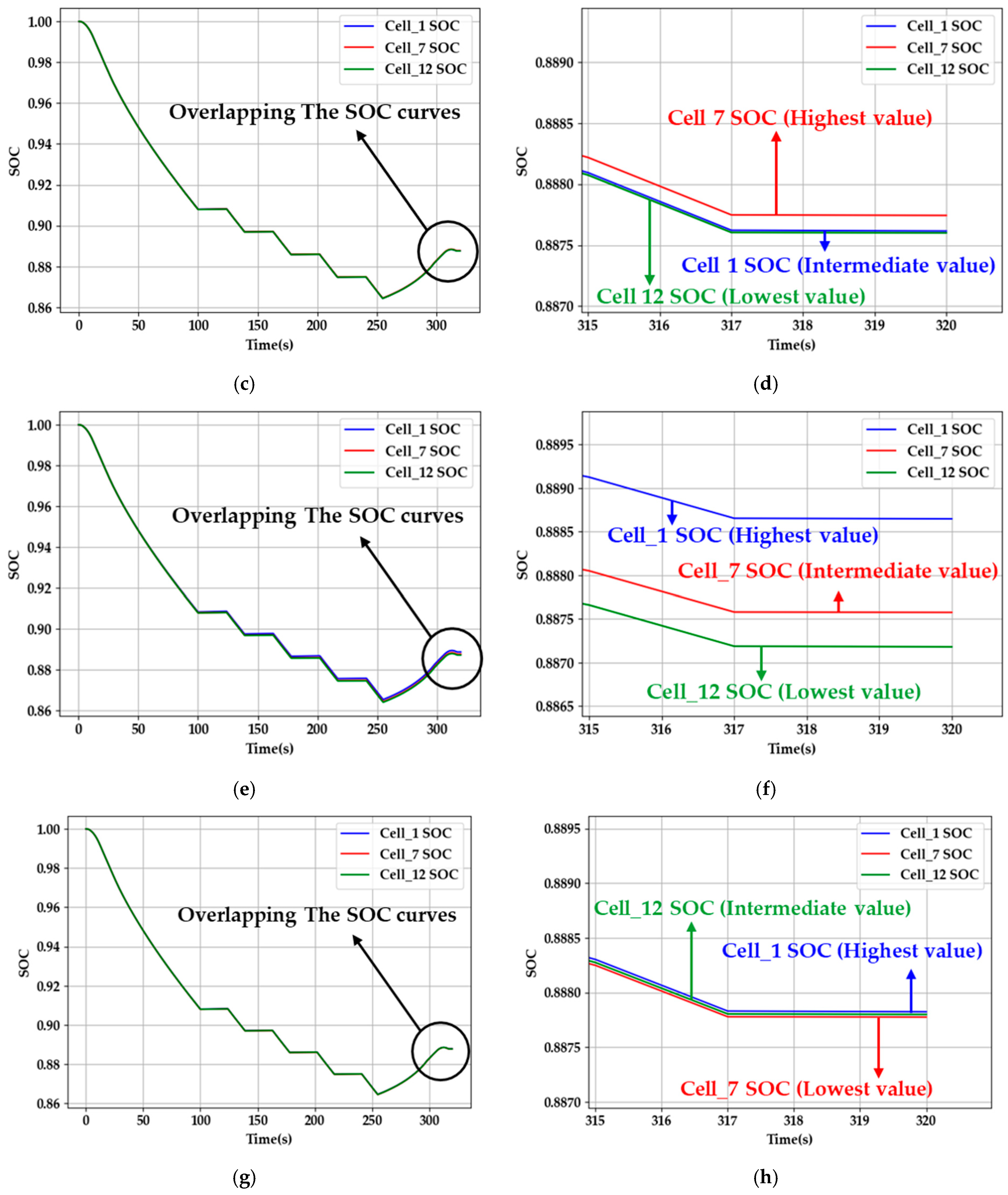
± 1   ° C
Table 3. Module simulation result.
Connecting MethodMaximum SOC DeviationCell_1Cell_7Cell_12
Single Connection0.000390.88730.88770.8876
Center Connection0.000140.88760.88770.8876
Diagonal Connection0.001460.88860.88750.8871
Proposal Connection0.000040.88780.88770.8877
Disclaimer/Publisher’s Note: The statements, opinions and data contained in all publications are solely those of the individual author(s) and contributor(s) and not of MDPI and/or the editor(s). MDPI and/or the editor(s) disclaim responsibility for any injury to people or property resulting from any ideas, methods, instructions or products referred to in the content.

